EP3529005B1 - Werkzeug und verfahren zum entgraten eines ojektes - Google Patents
Werkzeug und verfahren zum entgraten eines ojektes Download PDFInfo
- Publication number
- EP3529005B1 EP3529005B1 EP17790743.3A EP17790743A EP3529005B1 EP 3529005 B1 EP3529005 B1 EP 3529005B1 EP 17790743 A EP17790743 A EP 17790743A EP 3529005 B1 EP3529005 B1 EP 3529005B1
- Authority
- EP
- European Patent Office
- Prior art keywords
- fingers
- finger
- layers
- layer
- edge
- Prior art date
- Legal status (The legal status is an assumption and is not a legal conclusion. Google has not performed a legal analysis and makes no representation as to the accuracy of the status listed.)
- Active
Links
Images


Classifications
-
- B—PERFORMING OPERATIONS; TRANSPORTING
- B24—GRINDING; POLISHING
- B24D—TOOLS FOR GRINDING, BUFFING OR SHARPENING
- B24D13/00—Wheels having flexibly-acting working parts, e.g. buffing wheels; Mountings therefor
- B24D13/02—Wheels having flexibly-acting working parts, e.g. buffing wheels; Mountings therefor acting by their periphery
- B24D13/04—Wheels having flexibly-acting working parts, e.g. buffing wheels; Mountings therefor acting by their periphery comprising a plurality of flaps or strips arranged around the axis
-
- B—PERFORMING OPERATIONS; TRANSPORTING
- B24—GRINDING; POLISHING
- B24B—MACHINES, DEVICES, OR PROCESSES FOR GRINDING OR POLISHING; DRESSING OR CONDITIONING OF ABRADING SURFACES; FEEDING OF GRINDING, POLISHING, OR LAPPING AGENTS
- B24B29/00—Machines or devices for polishing surfaces on work by means of tools made of soft or flexible material with or without the application of solid or liquid polishing agents
- B24B29/005—Machines or devices for polishing surfaces on work by means of tools made of soft or flexible material with or without the application of solid or liquid polishing agents using brushes
-
- B—PERFORMING OPERATIONS; TRANSPORTING
- B24—GRINDING; POLISHING
- B24B—MACHINES, DEVICES, OR PROCESSES FOR GRINDING OR POLISHING; DRESSING OR CONDITIONING OF ABRADING SURFACES; FEEDING OF GRINDING, POLISHING, OR LAPPING AGENTS
- B24B9/00—Machines or devices designed for grinding edges or bevels on work or for removing burrs; Accessories therefor
- B24B9/02—Machines or devices designed for grinding edges or bevels on work or for removing burrs; Accessories therefor characterised by a special design with respect to properties of materials specific to articles to be ground
- B24B9/04—Machines or devices designed for grinding edges or bevels on work or for removing burrs; Accessories therefor characterised by a special design with respect to properties of materials specific to articles to be ground of metal, e.g. skate blades
-
- B—PERFORMING OPERATIONS; TRANSPORTING
- B24—GRINDING; POLISHING
- B24D—TOOLS FOR GRINDING, BUFFING OR SHARPENING
- B24D13/00—Wheels having flexibly-acting working parts, e.g. buffing wheels; Mountings therefor
- B24D13/02—Wheels having flexibly-acting working parts, e.g. buffing wheels; Mountings therefor acting by their periphery
- B24D13/06—Wheels having flexibly-acting working parts, e.g. buffing wheels; Mountings therefor acting by their periphery the flaps or strips being individually attached
-
- B—PERFORMING OPERATIONS; TRANSPORTING
- B24—GRINDING; POLISHING
- B24D—TOOLS FOR GRINDING, BUFFING OR SHARPENING
- B24D13/00—Wheels having flexibly-acting working parts, e.g. buffing wheels; Mountings therefor
- B24D13/14—Wheels having flexibly-acting working parts, e.g. buffing wheels; Mountings therefor acting by the front face
- B24D13/16—Wheels having flexibly-acting working parts, e.g. buffing wheels; Mountings therefor acting by the front face comprising pleated flaps or strips
-
- B—PERFORMING OPERATIONS; TRANSPORTING
- B24—GRINDING; POLISHING
- B24D—TOOLS FOR GRINDING, BUFFING OR SHARPENING
- B24D9/00—Wheels or drums supporting in exchangeable arrangement a layer of flexible abrasive material, e.g. sandpaper
- B24D9/006—Tools consisting of a rolled strip of flexible material
-
- B—PERFORMING OPERATIONS; TRANSPORTING
- B24—GRINDING; POLISHING
- B24B—MACHINES, DEVICES, OR PROCESSES FOR GRINDING OR POLISHING; DRESSING OR CONDITIONING OF ABRADING SURFACES; FEEDING OF GRINDING, POLISHING, OR LAPPING AGENTS
- B24B29/00—Machines or devices for polishing surfaces on work by means of tools made of soft or flexible material with or without the application of solid or liquid polishing agents
- B24B29/02—Machines or devices for polishing surfaces on work by means of tools made of soft or flexible material with or without the application of solid or liquid polishing agents designed for particular workpieces
- B24B29/06—Machines or devices for polishing surfaces on work by means of tools made of soft or flexible material with or without the application of solid or liquid polishing agents designed for particular workpieces for elongated workpieces having uniform cross-section in one main direction
Definitions
- the invention relates to a tool for machining an object, which tool has a plurality of fingers arranged in layers, the fingers being spaced apart from one another within the layers.
- Burrs can occur during workpiece processing. These usually sharp edges can cause injuries during component handling and/or compromise subsequent process steps (e.g., edge misalignment during powder coating, inaccurate fit, etc.).
- burr removal often requires a two-step process. In the first step, the primary burr is removed, followed by the secondary burr. The second step is often necessary because the primary burr is not completely removed but reshaped. In addition to deburring, edge rounding is often required to meet additional quality requirements.
- Deburring and rounding machines have become established in the field of deburring and edge rounding of 2D and, in some cases, 3D workpieces. These machines typically employ a grinding belt or disc unit with grinding belts or grinding wheels to remove the primary burr, and then remove or create the secondary burr or edge rounding using deburring and rounding tools. Edge rounding is considered critical as the radius increases. The quadratic relationship between radius and chip volume places considerable demands on the tools used. Doubling the edge radius quadruples the chip volume.
- the machine To achieve greater edge rounding with a given tool and workpiece, the machine must be operated in such a way that the rounding tools have the longest possible contact time (low feed rate) and are infeeded correspondingly deep to the workpiece edges.
- the long contact time and deep infeed lead to extended process times, increased tool wear, and undesirable heat input into the workpiece.
- the low feed rate for edge rounding is disproportionate to the primary burr removal. While primary burr removal can be performed at feed rates between 1 and 10 m/min, feed rates between 0.2 and 0.5 m/min are used for intensive edge rounding.
- abrasive materials consisting of a combination of abrasive cloth and abrasive fleece are primarily used.
- the abrasive materials are primarily coated abrasives.
- soft intermediate or support layers e.g., abrasive fleece, Tampico fiber.
- the tools can be designed as rollers, discs, or blocks.
- the US 5,301,472 A which forms the basis for the preamble of claim 1, describes a grinding tool for grinding wood.
- the base can advantageously be made of cotton, polyester or polycotton or consist of it.
- the finger layers themselves can also contain or consist of a grinding and/or abrasive material. In this case, no grinding or abrasive material needs to be applied to the fingers.
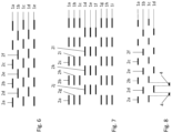
- the individual fingers can themselves be slit.
- Slits can be provided in the fingers, penetrating the fingers and extending parallel to the longitudinal direction of the fingers.
- several slits can also be arranged one behind the other along a straight line, whereby the straight line can run parallel to the longitudinal axes of the fingers.
- several parallel slits or several parallel rows of slits can be provided in each finger.
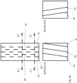
- all finger layers can be arranged parallel to one another, so that a surface spanned by the finger layers is rectangular perpendicular to the longitudinal directions of the fingers.
- the entire tool preferably has a block shape.
- the tool can advantageously have an extension of greater than or equal to 50 mm, preferably greater than or equal to 70 mm, and/or less than or equal to 100 mm, preferably less than or equal to 80 mm, in the direction in which the fingers of the same layers are arranged next to one another.
- This extension is referred to herein as the width of the tool.
- a depth or length of the tool i.e. an extension of the tool in the direction in which the finger layers are arranged one behind the other, can preferably be greater than or equal to 50 mm, preferably greater than or equal to 60 mm and/or less than or equal to 80 mm, preferably less than or equal to 70 mm.
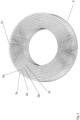
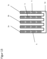
- a plurality of further finger layers are provided, which are arranged along a further closed circular line.
- the further closed circular line can run concentrically to the circular line of the aforementioned first finger arrangement and have a larger or smaller radius than the aforementioned first circular line.
- the further finger layers can therefore run inside or outside the first-described finger layers.
- the fingers of the further finger layers have the same length as the fingers of the first finger layers and are arranged such that the ends of the further fingers run in the same planes as the ends of the fingers of the first finger layers.
- the tool in the case of a plate-shaped arrangement, can have a diameter in the plane of the circular line of greater than or equal to 50 mm, preferably greater than or equal to 80 mm, preferably greater than or equal to 100 mm, preferably greater than or equal to 115 mm, preferably greater than or equal to 125 mm, preferably greater than or equal to 150 mm and/or less than or equal to 1500 mm, preferably less than or equal to 1000 mm, preferably less than or equal to 400 mm, preferably less than or equal to 250 mm, preferably less than or equal to 200 mm.
- the finger layers can have a width of greater than or equal to 15 mm, preferably greater than or equal to 20 mm, preferably greater than or equal to 30 mm and/or less than or equal to 100 mm, preferably less than or equal to 65 mm, preferably less than or equal to 60 mm, preferably less than or equal to 50 mm, preferably less than or equal to 40 mm.
- a plurality of finger layers can be combined to form a block.
- each block can have a depth of greater than or equal to 20 mm, preferably greater than or equal to 35 mm, preferably greater than or equal to 45 mm, and/or less than or equal to 70 mm, preferably less than or equal to 55 mm, in the direction in which the finger layers are arranged one behind the other.
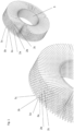
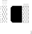
- the finger layers can be arranged one behind the other along a closed circular line, wherein the layer surfaces are again perpendicular to the circular line and wherein the fingers extend radially in their longitudinal direction to an axis which runs through the center of the circular line and is perpendicular to the circular area enclosed by the circular line.
- This embodiment of the tool is referred to below as a cylindrical embodiment.
- the tips of the fingers can lie on a common cylindrical surface.
- the points on the fingers to which they are attached can lie on a common cylindrical surface.
- the finger layers are normally at an angle to one another around the aforementioned axis.
- the fingers can preferably be arranged on a cylindrical support structure.
- a width of the tool i.e. its extension in the direction perpendicular to the circular area enclosed by the closed circular line or in the direction of the axis, can preferably be greater than or equal to 20 mm, preferably greater than or equal to 100 mm, preferably greater than or equal to 500 mm, preferably greater than or equal to 1,500 mm and/or less than or equal to 2,500 mm, preferably less than or equal to 2,000 mm, particularly preferably less than or equal to 1,700 mm.
- laminated main finger layers can optionally be used to influence the stiffness of the elements.
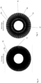
- the outermost fingers of each finger layer can be tapered downwards toward the edge of the finger layer.
- the fingers can become shorter toward the edge.
- the fingers can also become narrower toward the edge. This design achieves a smoother grip.
- the invention also provides a method for removing secondary burrs on one or more edges of a metallic workpiece and/or for rounding one or more edges of a metallic workpiece.
- a tool as described above, is moved over the edge to be machined so that the finger layers brush the edge. By brushing the edge with the finger layers, a secondary burr on the edge is removed and/or the edge is rounded.
- the tool is moved in a direction perpendicular to the edge to be machined.
- the tool is also moved in a direction that is not parallel to the finger positions in the undeflected state.
- the direction can be perpendicular to the finger positions in the undeflected state.
- a method for deburring and rounding one or more edges of a metallic workpiece wherein a tool, as described above, is moved over the edge in such a way that the finger layers brush the edge, so that the brushing of the edge by the finger layers removes a primary burr on the edge and the edge is rounded.
- the tool is advantageously moved in a direction perpendicular to the edge to be machined.
- the tool can be moved in a direction perpendicular to the layer surfaces in the undeflected state.
- the design of the tool according to the invention makes it possible both to remove a primary burr and to round off the edge. The primary burr removal and the rounding can be effected in a single step.
- the invention significantly increases the tool's removal rate compared to state-of-the-art tools of the same size. This allows for more pronounced edge rounding within a shorter time, improving production efficiency. Furthermore, the increased performance enables the integration of process steps that are performed independently in the prior art. For example, the process steps of primary burr removal, secondary burr removal, and edge rounding can be combined into a single process thanks to the invention's high removal rate. This opens up entirely new machine configurations.
- Tool according to an advantageous embodiment of the invention wherein the layer surfaces are flat in the undeflected state.
- the finger layers enclose an angle of greater than zero degrees and less than 180 degrees with a line along which the finger layers are arranged one behind the other.
- the fingers each have at least one grinding and/or abrasive surface which is parallel to the surface in which the corresponding finger extends flatly.
- the fingers are designed as abrasive means on a backing, wherein the abrasive means is applied to the grinding and/or abrasive surface.
- the fingers have a cotton, polyester or polycotton base.
- adjacent finger layers are designed in such a way that these finger layers, when placed on top of each other, completely fill a rectangular area.
- a length of the fingers in the direction perpendicular to the direction in which the fingers of the same finger layer are arranged next to one another and perpendicular to the direction in which the finger layers are arranged one behind the other is greater than or equal to 20 mm, preferably greater than or equal to 30 mm, particularly preferably greater than or equal to 40 mm and/or less than or equal to 150 mm, preferably less than or equal to 120 mm, preferably less than or equal to 90 mm, preferably less than or equal to 70 mm, preferably less than or equal to 60 mm, particularly preferably less than or equal to 50 mm.
- a width of the fingers in the direction in which the fingers of the same layer are arranged next to each other is greater than or equal to 1 mm, preferably greater than or equal to 2 mm, preferably greater than or equal to 3 mm, preferably greater than or equal to 5 mm and/or less than or equal to 20 mm, preferably less than or equal to 15 mm, particularly preferably less than or equal to 10 mm, preferably less than or equal to 7 mm.
- the tool has a width of greater than or equal to 20 mm, preferably greater than or equal to 70 mm and/or less than or equal to 100 mm, preferably less than or equal to 80 mm, preferably less than or equal to 65 mm, particularly preferably equal to 50 mm, in the direction in which the fingers of the same layers are arranged next to one another.
- the tool has a depth of greater than or equal to 30 mm, preferably greater than or equal to 40 mm and/or less than or equal to 70 mm, preferably less than or equal to 60 mm, particularly preferably equal to 55 mm, in the direction in which the finger layers are arranged one behind the other.
- the tool has a diameter of greater than or equal to 50 mm, preferably greater than or equal to 80 mm, preferably greater than or equal to 100 mm, preferably greater than or equal to 115 mm, preferably greater than or equal to 125 mm, preferably greater than or equal to 150 mm and/or less than or equal to 1500 mm, preferably less than or equal to 1000 mm, preferably less than or equal to 400 mm, preferably less than or equal to 250 mm, preferably less than or equal to 200 mm.
- the finger layers in the direction in which the fingers of the same layers are arranged next to each other have a width of greater than or equal to 15 mm, preferably greater than or equal to 20 mm, preferably greater than or equal to 30 mm and/or less than or equal to 100 mm, preferably less than or equal to 60 mm, preferably less than or equal to 50 mm, preferably less than or equal to 40 mm.
- a plurality of the finger layers are combined to form a block which preferably has a depth of greater than or equal to 20 mm, preferably greater than or equal to 35 mm, preferably greater than or equal to 45 mm and/or less than or equal to 70 mm, preferably less than or equal to 55 mm in the direction in which the finger layers are arranged one behind the other.
- a diameter of the tool in the direction radial to the circular line is greater than or equal to 50 mm, preferably greater than or equal to 100 mm, preferably greater than or equal to 200 mm and/or less than or equal to 400 mm, preferably less than or equal to 300 mm.
- a width of the tool in the direction perpendicular to the closed circular line is greater than or equal to 20 mm, preferably greater than or equal to 100 mm, preferably greater than or equal to 500 mm, preferably greater than or equal to 1500 mm and/or less than or equal to 2500 mm, preferably less than or equal to 2000 mm, preferably less than or equal to 1700 mm.
- the tool is a tool for deburring and/or rounding edges of a workpiece, preferably a metallic workpiece, and/or is a deburring and/or rounding tool.
Landscapes
- Engineering & Computer Science (AREA)
- Mechanical Engineering (AREA)
- Polishing Bodies And Polishing Tools (AREA)
- Finish Polishing, Edge Sharpening, And Grinding By Specific Grinding Devices (AREA)
- Grinding And Polishing Of Tertiary Curved Surfaces And Surfaces With Complex Shapes (AREA)
Priority Applications (1)
| Application Number | Priority Date | Filing Date | Title |
|---|---|---|---|
| EP25179346.9A EP4588614A3 (de) | 2016-10-21 | 2017-10-20 | Werkzeug zum bearbeiten eines objektes |
Applications Claiming Priority (2)
| Application Number | Priority Date | Filing Date | Title |
|---|---|---|---|
| DE102016220766.0A DE102016220766B4 (de) | 2016-10-21 | 2016-10-21 | Werkzeug zum Bearbeiten eines Objektes |
| PCT/EP2017/076896 WO2018073432A1 (de) | 2016-10-21 | 2017-10-20 | Werkzeug und verfahren zum entgraten eines ojektes |
Related Child Applications (2)
| Application Number | Title | Priority Date | Filing Date |
|---|---|---|---|
| EP25179346.9A Division-Into EP4588614A3 (de) | 2016-10-21 | 2017-10-20 | Werkzeug zum bearbeiten eines objektes |
| EP25179346.9A Division EP4588614A3 (de) | 2016-10-21 | 2017-10-20 | Werkzeug zum bearbeiten eines objektes |
Publications (3)
| Publication Number | Publication Date |
|---|---|
| EP3529005A1 EP3529005A1 (de) | 2019-08-28 |
| EP3529005B1 true EP3529005B1 (de) | 2025-07-09 |
| EP3529005C0 EP3529005C0 (de) | 2025-07-09 |
Family
ID=60182559
Family Applications (2)
| Application Number | Title | Priority Date | Filing Date |
|---|---|---|---|
| EP17790743.3A Active EP3529005B1 (de) | 2016-10-21 | 2017-10-20 | Werkzeug und verfahren zum entgraten eines ojektes |
| EP25179346.9A Pending EP4588614A3 (de) | 2016-10-21 | 2017-10-20 | Werkzeug zum bearbeiten eines objektes |
Family Applications After (1)
| Application Number | Title | Priority Date | Filing Date |
|---|---|---|---|
| EP25179346.9A Pending EP4588614A3 (de) | 2016-10-21 | 2017-10-20 | Werkzeug zum bearbeiten eines objektes |
Country Status (7)
| Country | Link |
|---|---|
| US (1) | US20200180113A1 (pl) |
| EP (2) | EP3529005B1 (pl) |
| JP (1) | JP7211955B2 (pl) |
| DE (1) | DE102016220766B4 (pl) |
| ES (1) | ES3041642T3 (pl) |
| PL (1) | PL3529005T3 (pl) |
| WO (1) | WO2018073432A1 (pl) |
Families Citing this family (1)
| Publication number | Priority date | Publication date | Assignee | Title |
|---|---|---|---|---|
| DE102018106347A1 (de) | 2018-03-19 | 2019-09-19 | Boeck Gmbh | Verbindungsvorrichtung |
Family Cites Families (24)
| Publication number | Priority date | Publication date | Assignee | Title |
|---|---|---|---|---|
| US2948090A (en) * | 1960-08-09 | Abrasive wheels | ||
| US3043063A (en) * | 1958-12-08 | 1962-07-10 | Osborn Mfg Co | Rotary tool |
| JPS51102364A (ja) * | 1975-03-06 | 1976-09-09 | Sugimoto Soki Kogyo Kk | Katsutaaburashi |
| DE2519363A1 (de) * | 1975-04-30 | 1976-11-11 | Sugimoto Sohki Kogyo Co Ltd | Aus einzelnen zungen zusammensetzbare schleifbuerste |
| US4646479A (en) * | 1981-09-25 | 1987-03-03 | Avco Corporation | Deburring method |
| JPH0357426Y2 (pl) * | 1984-09-19 | 1991-12-27 | ||
| US5301472A (en) * | 1991-05-20 | 1994-04-12 | Lyng James W | Sanding element and apparatus |
| US6793569B2 (en) * | 2000-04-10 | 2004-09-21 | Poul Lundum | Sanding strip |
| US7237253B1 (en) * | 2000-04-27 | 2007-06-26 | Microsoft Corporation | User interface for interactive television systems |
| NL1018937C2 (nl) * | 2001-09-12 | 2003-03-13 | Timesavers Internat B V | Inrichting voor het bewerken van vlakke werkstukken. |
| US6840848B1 (en) * | 2002-12-04 | 2005-01-11 | Ralph E. Dyar | Bushings and abrasive wheel therewith |
| US7121937B2 (en) * | 2003-03-17 | 2006-10-17 | 3M Innovative Properties Company | Abrasive brush elements and segments |
| US6949019B2 (en) * | 2004-01-12 | 2005-09-27 | Belanger Industrial Products, Inc. | Flap-type rotary finishing device |
| US20050260940A1 (en) * | 2004-05-21 | 2005-11-24 | Simon Palushaj | Abrasive cleaning device |
| US7988539B2 (en) * | 2004-05-21 | 2011-08-02 | Epoxi-Tech, Inc. | Abrasive cleaning device |
| WO2008093785A1 (ja) * | 2007-01-31 | 2008-08-07 | Sanko Sangyo Co., Ltd. | 表面処理用ブラシ及び表面処理装置 |
| JP5306619B2 (ja) * | 2007-09-06 | 2013-10-02 | スリーエム イノベイティブ プロパティズ カンパニー | 線形研磨ブラシ部材、線形研磨ブラシ部材の製造方法、及び研磨ブラシ |
| JP5945679B2 (ja) * | 2012-07-17 | 2016-07-05 | 株式会社光陽社 | バリ取りブラシ用の研磨布紙保持具、及びこれを用いたバリ取りブラシ用のブラシ構成盤、並びにこれを積層して成るバリ取り用ブラシ |
| JP6357719B2 (ja) * | 2014-04-08 | 2018-07-18 | 三光産業株式会社 | 表面処理用ブラシ及び表面処理装置 |
| DE112014007101T5 (de) * | 2014-10-27 | 2017-07-20 | Taimei Chemicals Co., Ltd | Schleifbürste |
| DE202015102354U1 (de) * | 2015-05-08 | 2015-05-22 | Arku Maschinenbau Gmbh | Bearbeitungseinheit für eine Maschine zum Entgraten eines flächigen Werkstücks |
| DE202015106711U1 (de) | 2015-12-09 | 2017-03-10 | Kolthoff Gabrovo Eood | Werkzeug für Oberflächenfeinbearbeitungen |
| DE102016101525B4 (de) | 2016-01-28 | 2019-08-22 | Gottfried Wilhelm Leibniz Universität Hannover | Verfahren zur Bearbeitung einer Werkzeugkante eines Zerspanwerkzeugs und Bürstschleifmaschine |
| JP6786075B2 (ja) * | 2016-07-15 | 2020-11-18 | 大明化学工業株式会社 | ホイールブラシおよび砥材束ホルダ |
-
2016
- 2016-10-21 DE DE102016220766.0A patent/DE102016220766B4/de active Active
-
2017
- 2017-10-20 EP EP17790743.3A patent/EP3529005B1/de active Active
- 2017-10-20 US US16/343,321 patent/US20200180113A1/en active Pending
- 2017-10-20 WO PCT/EP2017/076896 patent/WO2018073432A1/de not_active Ceased
- 2017-10-20 ES ES17790743T patent/ES3041642T3/es active Active
- 2017-10-20 PL PL17790743.3T patent/PL3529005T3/pl unknown
- 2017-10-20 EP EP25179346.9A patent/EP4588614A3/de active Pending
- 2017-10-20 JP JP2019542792A patent/JP7211955B2/ja active Active
Also Published As
| Publication number | Publication date |
|---|---|
| US20200180113A1 (en) | 2020-06-11 |
| EP3529005C0 (de) | 2025-07-09 |
| EP4588614A2 (de) | 2025-07-23 |
| PL3529005T3 (pl) | 2025-11-12 |
| JP7211955B2 (ja) | 2023-01-24 |
| WO2018073432A1 (de) | 2018-04-26 |
| ES3041642T3 (en) | 2025-11-13 |
| JP2019532830A (ja) | 2019-11-14 |
| DE102016220766A1 (de) | 2018-05-09 |
| EP4588614A3 (de) | 2025-11-05 |
| DE102016220766B4 (de) | 2018-08-23 |
| EP3529005A1 (de) | 2019-08-28 |
Similar Documents
| Publication | Publication Date | Title |
|---|---|---|
| DE112007003696B4 (de) | Gewindefräser | |
| DE102011116842B4 (de) | Schleifvorrichtung | |
| DE102010010758B4 (de) | Spitzenlose Rundschleifmaschine zum Schleifen von stangenförmigen Werkstücken und Verfahren zum spitzenlosen Rundschleifen von stangenförmigen Werkstücken | |
| DE2638362A1 (de) | Fraeswalze fuer eine holzabrichtmaschine | |
| EP3043962B1 (de) | Schneidwerkzeug | |
| DE29715192U1 (de) | Fräswerkzeug | |
| DE3346189C1 (de) | Abrichtwerkzeug zum Abrichten von abrasiven zahnradartigen Feinbearbeitungswerkzeugen | |
| EP3804907B1 (de) | Verfahren zur herstellung einer abrasiveinheit | |
| DE3114687A1 (de) | Schneidblatt | |
| AT15155U1 (de) | Schälplatte | |
| EP3141327B1 (de) | Verfahren zum abrichten einer mehrgängigen schleifschnecke | |
| EP3529005B1 (de) | Werkzeug und verfahren zum entgraten eines ojektes | |
| EP3738713B1 (de) | Verfahren zur oberflächenbearbeitung einer gesteins- und/oder betonoberfläche | |
| DE102018114138A1 (de) | Tieflochbohrer mit mehreren Spanformern und Mulden in der Spanfläche | |
| EP0761357B1 (de) | Verfahren zum Schaben oder Schabschleifen zylindrischer, insbesondere flankenlinienmodifizierter Zahnräder bzw. zum Profilieren der zum Schabschleifen benötigten Werkzeuge | |
| DE4216329C1 (pl) | ||
| EP0033562A2 (de) | Bearbeitungskörper für das Gleitschleifverfahren | |
| EP1743737B1 (de) | Durchlaufschleifmaschine zum Bearbeiten einer ebenen Werkstückoberfläche | |
| DE602004006149T3 (de) | Schleifgerät, dessen Anwendung zum Schleifen von zylindrischen Gegenständen , Vorrichtung und Verfahren zum Schleifen von zylindrischen Gegenständen | |
| DE19639453B4 (de) | Schleifvorrichtung | |
| DE102019135530A1 (de) | Vorrichtung zur Finishbearbeitung von Wälzkörpern | |
| DE926424C (de) | Verfahren und Vorrichtung zur Herstellung von Ausschnitten in Metallstreifen oder -baendern | |
| AT406129B (de) | Vorrichtung zum spanabhebenden bearbeiten einer streifenförmigen werkstückfläche | |
| DE102014011292A1 (de) | Perfektionierte, mit Drehscheiben ausgestattete Bearbeitungsvorrichtung und entsprechendes Bearbeitungsmodul | |
| EP3181293A1 (de) | Finishwerkzeug mit lokal variierender schnittigkeit |
Legal Events
| Date | Code | Title | Description |
|---|---|---|---|
| STAA | Information on the status of an ep patent application or granted ep patent |
Free format text: STATUS: UNKNOWN |
|
| STAA | Information on the status of an ep patent application or granted ep patent |
Free format text: STATUS: THE INTERNATIONAL PUBLICATION HAS BEEN MADE |
|
| PUAI | Public reference made under article 153(3) epc to a published international application that has entered the european phase |
Free format text: ORIGINAL CODE: 0009012 |
|
| STAA | Information on the status of an ep patent application or granted ep patent |
Free format text: STATUS: REQUEST FOR EXAMINATION WAS MADE |
|
| 17P | Request for examination filed |
Effective date: 20190521 |
|
| AK | Designated contracting states |
Kind code of ref document: A1 Designated state(s): AL AT BE BG CH CY CZ DE DK EE ES FI FR GB GR HR HU IE IS IT LI LT LU LV MC MK MT NL NO PL PT RO RS SE SI SK SM TR |
|
| AX | Request for extension of the european patent |
Extension state: BA ME |
|
| DAV | Request for validation of the european patent (deleted) | ||
| DAX | Request for extension of the european patent (deleted) | ||
| STAA | Information on the status of an ep patent application or granted ep patent |
Free format text: STATUS: EXAMINATION IS IN PROGRESS |
|
| 17Q | First examination report despatched |
Effective date: 20220826 |
|
| GRAP | Despatch of communication of intention to grant a patent |
Free format text: ORIGINAL CODE: EPIDOSNIGR1 |
|
| STAA | Information on the status of an ep patent application or granted ep patent |
Free format text: STATUS: GRANT OF PATENT IS INTENDED |
|
| INTG | Intention to grant announced |
Effective date: 20250128 |
|
| GRAS | Grant fee paid |
Free format text: ORIGINAL CODE: EPIDOSNIGR3 |
|
| GRAA | (expected) grant |
Free format text: ORIGINAL CODE: 0009210 |
|
| STAA | Information on the status of an ep patent application or granted ep patent |
Free format text: STATUS: THE PATENT HAS BEEN GRANTED |
|
| AK | Designated contracting states |
Kind code of ref document: B1 Designated state(s): AL AT BE BG CH CY CZ DE DK EE ES FI FR GB GR HR HU IE IS IT LI LT LU LV MC MK MT NL NO PL PT RO RS SE SI SK SM TR |
|
| REG | Reference to a national code |
Ref country code: GB Ref legal event code: FG4D Free format text: NOT ENGLISH |
|
| REG | Reference to a national code |
Ref country code: CH Ref legal event code: EP |
|
| REG | Reference to a national code |
Ref country code: IE Ref legal event code: FG4D Free format text: LANGUAGE OF EP DOCUMENT: GERMAN |
|
| REG | Reference to a national code |
Ref country code: DE Ref legal event code: R096 Ref document number: 502017016957 Country of ref document: DE |
|
| U01 | Request for unitary effect filed |
Effective date: 20250808 |
|
| U07 | Unitary effect registered |
Designated state(s): AT BE BG DE DK EE FI FR IT LT LU LV MT NL PT RO SE SI Effective date: 20250820 |
|
| U20 | Renewal fee for the european patent with unitary effect paid |
Year of fee payment: 9 Effective date: 20250825 |
|
| REG | Reference to a national code |
Ref country code: CH Ref legal event code: U11 Free format text: ST27 STATUS EVENT CODE: U-0-0-U10-U11 (AS PROVIDED BY THE NATIONAL OFFICE) Effective date: 20251101 |
|
| REG | Reference to a national code |
Ref country code: ES Ref legal event code: FG2A Ref document number: 3041642 Country of ref document: ES Kind code of ref document: T3 Effective date: 20251113 |