EP3528973B1 - Reinigungs-, desinfektions- und trocknungs-anlage - Google Patents
Reinigungs-, desinfektions- und trocknungs-anlage Download PDFInfo
- Publication number
- EP3528973B1 EP3528973B1 EP17791938.8A EP17791938A EP3528973B1 EP 3528973 B1 EP3528973 B1 EP 3528973B1 EP 17791938 A EP17791938 A EP 17791938A EP 3528973 B1 EP3528973 B1 EP 3528973B1
- Authority
- EP
- European Patent Office
- Prior art keywords
- washing
- washing chamber
- devices
- installation
- chamber
- Prior art date
- Legal status (The legal status is an assumption and is not a legal conclusion. Google has not performed a legal analysis and makes no representation as to the accuracy of the status listed.)
- Active
Links
- 238000001035 drying Methods 0.000 title claims description 19
- 238000004140 cleaning Methods 0.000 title claims description 18
- 238000004659 sterilization and disinfection Methods 0.000 title description 6
- 238000005406 washing Methods 0.000 claims description 63
- 239000000463 material Substances 0.000 claims description 9
- 239000007921 spray Substances 0.000 claims description 7
- 238000005516 engineering process Methods 0.000 claims description 6
- 239000007788 liquid Substances 0.000 claims description 6
- 238000004519 manufacturing process Methods 0.000 claims description 5
- 239000000969 carrier Substances 0.000 claims description 4
- 238000005273 aeration Methods 0.000 claims description 3
- 230000000249 desinfective effect Effects 0.000 claims description 3
- 239000003795 chemical substances by application Substances 0.000 claims description 2
- 238000007789 sealing Methods 0.000 claims description 2
- 238000009434 installation Methods 0.000 claims 6
- 238000002360 preparation method Methods 0.000 claims 1
- 239000003570 air Substances 0.000 description 17
- 238000005202 decontamination Methods 0.000 description 4
- 230000003588 decontaminative effect Effects 0.000 description 4
- 238000000034 method Methods 0.000 description 4
- 208000015181 infectious disease Diseases 0.000 description 2
- 230000003389 potentiating effect Effects 0.000 description 2
- 238000009423 ventilation Methods 0.000 description 2
- 239000012080 ambient air Substances 0.000 description 1
- 230000004888 barrier function Effects 0.000 description 1
- 239000012459 cleaning agent Substances 0.000 description 1
- 238000011109 contamination Methods 0.000 description 1
- 239000000824 cytostatic agent Substances 0.000 description 1
- 230000001085 cytostatic effect Effects 0.000 description 1
- 230000001419 dependent effect Effects 0.000 description 1
- 238000011161 development Methods 0.000 description 1
- 230000018109 developmental process Effects 0.000 description 1
- 239000011521 glass Substances 0.000 description 1
- 230000003993 interaction Effects 0.000 description 1
- 239000002245 particle Substances 0.000 description 1
- 229910001220 stainless steel Inorganic materials 0.000 description 1
- 239000010935 stainless steel Substances 0.000 description 1
- 238000013022 venting Methods 0.000 description 1
Images

Classifications
-
- B—PERFORMING OPERATIONS; TRANSPORTING
- B08—CLEANING
- B08B—CLEANING IN GENERAL; PREVENTION OF FOULING IN GENERAL
- B08B15/00—Preventing escape of dirt or fumes from the area where they are produced; Collecting or removing dirt or fumes from that area
- B08B15/02—Preventing escape of dirt or fumes from the area where they are produced; Collecting or removing dirt or fumes from that area using chambers or hoods covering the area
- B08B15/026—Boxes for removal of dirt, e.g. for cleaning brakes, glove- boxes
-
- B—PERFORMING OPERATIONS; TRANSPORTING
- B08—CLEANING
- B08B—CLEANING IN GENERAL; PREVENTION OF FOULING IN GENERAL
- B08B3/00—Cleaning by methods involving the use or presence of liquid or steam
- B08B3/006—Cabinets or cupboards specially adapted for cleaning articles by hand
-
- B—PERFORMING OPERATIONS; TRANSPORTING
- B08—CLEANING
- B08B—CLEANING IN GENERAL; PREVENTION OF FOULING IN GENERAL
- B08B3/00—Cleaning by methods involving the use or presence of liquid or steam
- B08B3/04—Cleaning involving contact with liquid
- B08B3/10—Cleaning involving contact with liquid with additional treatment of the liquid or of the object being cleaned, e.g. by heat, by electricity or by vibration
- B08B3/14—Removing waste, e.g. labels, from cleaning liquid; Regenerating cleaning liquids
-
- B—PERFORMING OPERATIONS; TRANSPORTING
- B08—CLEANING
- B08B—CLEANING IN GENERAL; PREVENTION OF FOULING IN GENERAL
- B08B5/00—Cleaning by methods involving the use of air flow or gas flow
- B08B5/02—Cleaning by the force of jets, e.g. blowing-out cavities
-
- B—PERFORMING OPERATIONS; TRANSPORTING
- B25—HAND TOOLS; PORTABLE POWER-DRIVEN TOOLS; MANIPULATORS
- B25J—MANIPULATORS; CHAMBERS PROVIDED WITH MANIPULATION DEVICES
- B25J21/00—Chambers provided with manipulation devices
- B25J21/02—Glove-boxes, i.e. chambers in which manipulations are performed by the human hands in gloves built into the chamber walls; Gloves therefor
Definitions
- the invention relates to a cleaning, disinfection and drying system for the processing of accessories and/or.
- general items to be washed in particular in pharmaceutical production and medical technology, with a washroom provided with an access door, in or on which supply devices for washing liquids and drying air are arranged on spray nozzles and wash arms with spray nozzles.
- the invention relates to a cleaning, disinfection and drying system with an isolator system for processing accessories or general items to be washed in pharmaceutical production.
- a box-shaped cleaning device which has an opening on a side surface through which a gloved hand holding the part to be cleaned can reach into the interior of the container, with objects to be cleaned in the cleaning device being able to be cleaned with the aid of a spray device without the Infection carriers can get to the user's human skin or uncontrolled into the environment.
- a spray device without the Infection carriers can get to the user's human skin or uncontrolled into the environment.
- 5,273,060 discloses a cleaning, disinfecting and drying system with a washing chamber provided with an access door, in which supply lines for washing liquids and drying air are arranged on spray nozzles and washing arms with spray nozzles, with a glove carrier arranged in a wall of the washing chamber for gloves extending into the washing chamber Gloves, the supply air and exhaust air guiding devices being designed to maintain a differential pressure between the washing chamber and a work space.
- the document FR 2,842,739 discloses a cleaning, disinfecting and drying system with a washing chamber provided with an access door in which supply lines for washing liquids are arranged, the washing chamber being designed as an isolator system with a glove carrier arranged in a wall of the washing chamber for gloves extending into the washing chamber.
- the invention is based on the object of creating a cleaning, disinfection and drying system of the type mentioned at the outset which can be used in all clean room classes which are used in pharmaceutical production or medical technology.
- the washroom is designed as an isolator system and has washware carriers, supply air and exhaust air guide devices provided with filters, a glove carrier arranged in a wall of the wash chamber for gloves extending into the wash chamber for manipulating the items to be washed in the washing chamber, the supply air and exhaust air guiding devices being designed to maintain a differential pressure between the washing chamber and a working space in which the system is arranged,
- Separate supply and discharge devices for washing liquids and drying air, provided with filters, can be connected to the washing chamber.
- the glove carrier can be part of a windscreen for viewing the interior of the lavatory.
- the side access opening which can be closed by a door, can have devices for connecting to material locks for loading and unloading the washroom.
- the material locks can have ventilation devices that are separate from the washroom
- the focus is on personal protection, which is achieved by an interaction between the cleaning system and the isolator system, ie the cleaning and isolator function in a single washing chamber.
- the aim is to safely and consistently separate the operator from the product or from its manufacture in a closed system.
- isolators where cytostatics are manufactured, for example, there is permanent negative pressure.
- FIG 1 a schematic view of the cleaning, disinfection and drying system 1 is shown.
- the system 1 has a washing chamber 2, which is preferably made of stainless steel and has no dead space so that it can be cleaned easily.
- a support grid 4 is arranged, on which a laundry contained in an initially hermetically sealed container 3, shown only schematically, can be placed via a loading system, not shown.
- the loading system can be connected to a side access opening 16 of the washing chamber 2, and a material lock can be provided between the washing chamber 2 and the loading system.
- the connection between the washing chamber 2 and the loading system and optionally the material lock can be sealed by suitable hermetic seals, with a material lock having a separate ventilation and aeration system.
- the washing chamber 2 On the front side, the washing chamber 2 has a glove holder 7 for gloves extending into the washing chamber for manipulating the items to be washed in the washing chamber.
- the glove carrier 7 may be formed by a pane of glass carrying frames 8 for attachment of the open end of respective gloves.
- the glove carrier 7, the frame 8 and the outer peripheries of the gloves themselves are hermetically sealed from each other.
- the glove holder 7 can be covered by a cover flap 9 when the system (1) is not in use.
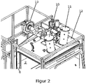
- filter nozzles 10, 11 for aerating and venting the washing chamber 2, as shown in particular figure 2 can be seen.
- One of the two filter nozzles 10, 11 is connected to the fan via a connecting line, while the other can be connected to the outside air via a separate connecting line.
- Throttle valves can be arranged in both connecting lines, which can be controlled via control devices in order to achieve a desired positive or negative pressure in the washing chamber 2 .
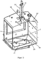
- nozzle assembly 14 On the upper side 12 of the washing chamber 2 there is also a sealing arrangement 16 for a nozzle assembly 14 which can be moved both axially and pivotably in this.
- This nozzle assembly 14 is connected to the washing agent and drying air supply of the washing chamber by a connecting line 15 and can, under manual or mechanical control, direct a jet onto otherwise difficult-to-reach areas of the laundry and/or the container initially accommodating it.
- the in the Figures 1 to 3 6 designated side opening of the washing chamber 2 is preferably hermetically sealed by a sliding door.
- the washing chamber 2 is arranged in a support frame 5 which, in addition to the washing chamber 2 , carries the supply devices required for its operation in a further chamber 6 .
- the system can be operated in the manner described below, which is only an example:
- the fully automatic sliding door in front of the side opening of the washing chamber is opened, whereupon the loading system, on which the items to be cleaned are located, is positioned in the washing area of the machine, with this positioning possibly being carried out via a material lock in front of the side opening.
- the contaminated items to be washed are placed in a hermetically sealed container so that, for example, highly potent contamination cannot come into contact with the operator.
- the automatic sliding door at the lateral access opening is closed again and compressed air is applied to this assigned door seal.
- the entire system is thus hermetically sealed.
- the operator can now remove the items to be cleaned using the gloves on the front and place them in the necessary cleaning positions.
- the sliding door located at the side access opening can be opened to assemble the items to be washed, or alternatively the items to be washed can be assembled outside of the washroom.
- the unloading process corresponds to the loading process as described above
- System 1 described above and its washing chamber 2 is, as already indicated, equipped with electronic controllable filter technology for circulating air, supply and exhaust air, can be equipped with connections for particle and germ count determination, monitors air speed and differential pressure for filters and work area, has a front pane with glove ports and material locks for loading and unloading the isolator formed by the washing chamber with separate fan technology.
Landscapes
- Engineering & Computer Science (AREA)
- Robotics (AREA)
- Mechanical Engineering (AREA)
- Cleaning By Liquid Or Steam (AREA)
- Apparatus For Disinfection Or Sterilisation (AREA)
- Accessory Of Washing/Drying Machine, Commercial Washing/Drying Machine, Other Washing/Drying Machine (AREA)
- Prevention Of Fouling (AREA)
- Apparatus Associated With Microorganisms And Enzymes (AREA)
Description
- Die Erfindung bezieht sich auf eine Reinigungs-, Desinfektions- und TrocknungsAnlage für die Aufbereitung von Zubehörteilen und/oder. allgemeinen Waschgütern insbesondere in der Pharmaproduktion und Medizintechnik, mit einem mit einer Zugangstür versehenen Waschraum, in bzw. an dem Zuführungseinrichtungen für Waschflüsigkeiten und Trocknungsluft an Sprühdüsen und Wascharme mit Sprühdüsen angeordnet sind.
- Die Erfindung betrifft eine Reinigungs-, Desinfektions- und Trocknungsanlage mit Isolatorsystem für die Aufbereitung von Zubehörteilen bzw. allgemeinen Waschgütern in der Pharmaproduktion.
- Aus der
DE 3608776 A1 ist ein kastenförmiges Reinigungsgerät bekannt, das an einer Seitenfläche eine Öffnung aufweist, durch die eine behandschuhte, das zu reinigende Teil haltende Hand in den Innenraum des Behälters hineingreifen kann, wobei zu reinigende Gegenstände in dem Reinigungsgerät mit Hilfe eine Sprüheinrichtung gereinigt werden können, ohne das Infektionsträger an die menschliche Haut des Benutzers oder unkontrolliert in die Umgebung gelangen können. Eine derartige Anordnung ist jedoch bei einer Vielzahl von zu reinigenden Gegenständen in der Anwendung umständlich und weist keine Einrichtungen zum Schutz gegen den Austritt von Infektionsträgern in die Umgebung auf. - Aus der
US 4,354,514 ist eine Vorrichtung von Schlauch- oder Ballon-förmigen Gegenständen bekannt, die eine Reinigungs- und Trocknungskammer mit einem Zuluftfilter zur Reinigung der Umgebungsluft und ein Abluftgebläse aufweist. Die zu reinigenden Gegenstände werden auf perforierte Rohre aufgezogen, die mit unter Druck stehendem Reinigungsmittel und Trocknungsluft für die zu reinigenden Gegenstände beaufschlagbar sind. Hierdurch ist sowohl eine Innenals auch eine Außenreinigung der zu reinigenden Gegegstände möglich. Möglichkeiten zur manuellen Handhabung und des Reinigungs- oder Bearbeitungsvorganges sind nicht vorgesehen. Das DokumentUS 5,273,060 offenbart eine Reinigungs-, Desinfektions- und Trocknungs-Anlage mit einer mit einer Zugangstür versehenen Waschkammer, in der Zuführungsleitungen für Waschflüssigkeiten und Trocknungsluft an Sprühdüsen und Wascharme mit Sprühdüsen angeordnet sind, mit einem in einer Wand der Waschkammer angeordneten Handschuhträger für sich in die Waschkammer erstreckende Handschuhe, wobei die Zuluft- und Abluft-Führungseinrichtungen zum Aufrechterhalten eines Differenzdruckes zwischen der Waschkammer und einem Arbeitsraum ausgebildet sind. - Das Dokument
FR 2,842,739 - Der Erfindung liegt die Aufgabe zugrunde, eine Reinigungs-, Desinfektions- und Trocknungs-Anlage der eingangs genannten Art zu schaffen, die allen Reinraumklassen, welche in der Pharmaproduktion oder Medizintechnik Verwendung finden, eingesetzt werden kann.
- Diese Aufgabe wird durch die im Anspruch 1 angegebenen Merkmale gelöst.
- Vorteilhafte Ausgestaltungen und Weiterbildungen der Erfindung ergeben sich aus den Unteransprüchen.
- Bei der erfindungsgemäßen Reinigungs-, Desinfektions- und Trocknungs-Anlage ist der Waschraum als Isolatorsystem ausgebildet ist und weist Waschgut-Träger, mit Filtern versehene Zuluft- und Abluft-Führungseinrichtungen, einen in einer Wand der Waschkammer angeordneten Handschuhträger für sich in die Waschkammer erstreckende Handschuhe zur Manipulation des in der Waschkammer befindlichen Waschgutes auf, wobei die Zuluft- und Abluft-Führungseinrichtungen zum Aufrechterhalten eines Differenzdruckes zwischen der Waschkammer und einem Arbeitsraum ausgebildet sind, in dem die Anlage angeordnet ist,
- Mit der Waschkammer können getrennte, mit Filtern versehene, Zuleitungs- und Ableitungseinrichtungen für Waschflüssigkeiten und Trocknungsluft verbunden sein. Der Handschuhträger kann Teil einer Frontscheibe zur Betrachtung der Innenraumes des Waschraums sein.
- Die durch eine Tür verschließbare seitliche Zugangsöffnung kann Einrichtungen zur Verbindung mit Materialschleusen für die Be- und Entladung des Waschraumes aufweisen.
- Die Materialschleusen können hierbei von dem Waschraum getrennte Be- und Entlüftungseinrichtungen aufweisen
- Bei der erfindungsgemäßen Anlage steht der Personenschutz im Vordergrund, was durch ein Zusammenspiel zwischen Reinigungsanlage und Isolatorsystem, d.h. Reinigungs- und Isolatorfunktion in einer einzigen Waschkammer erreicht wird.
- Ziel ist es, den Bediener sicher und konsequent vom Produkt beziehungsweise von dessen Herstellung in einem geschlossenen System zu trennen. In Isolatoren, wo zum Beispiel Zytostatika hergestellt werden, herrscht permanenter Unterdruck.
- Die Erfindung wird nachfolgend anhand eines in den Zeichnungen dargestellten Ausführungsbeispiels noch näher erläutert.
- In der Zeichnung zeigen :
- Figur 1
- eine schematische Teilansicht einer bevorzugten Ausführungsform der erfindungsgemäßen Anlage;
- Figur 2
- eine teilweise weggebrochene Ansicht der Oberseite einer Ausführungsform der Waschkammer 2;
- Figur 3
- eine Ansicht der Oberseite der Waschkammer, auf der ein verstellbarer Düsenstock angeordnet ist.
- In
Figur 1 ist eine schematische Ansicht der Reinigungs-, Desinfektions- und Trocknungs-Anlage 1 gezeigt, Die Anlage 1 weist eine Waschkammer 2 auf, die vorzugsweise aus Edelstahl hergestellt ist und keinen Totraum besitzt, damit sie gut zu reinigen ist. In der Waschkammer 2 ist ein Auflagegitter 4 angeordnet, auf dem ein in einem zunächst hermetisch abgeschlossenen, nur schematisch dargestellten, Behälter 3 enthaltenes Waschgut über ein nicht dargestelltes Zuladungssystem ablegbar ist. - Das Zuladungssystem ist mit einer seitlichen Zugangsöffnung 16 der Waschkammer 2 verbindbar, wobei zwischen der Waschkammer 2 und dem Zuladungssystem eine Materialschleuse vorgesehen sein kann. Die Verbindung zwischen der Waschkammer 2 und dem Zuladungssystem und gegebenfalls der Material-schleuse kann durch geeignete hermetische Dichtungen abgedichtet sein, wobei eine Materialschleuse ein getrenntes Be- und Entlüftungssystem aufweist. An der Frontseite weist die Waschkammer 2 einen Handschuhträger 7 für sich in die Waschkammer erstreckende Handschuhe zur Manipulation des in der Waschkammer befindlichen Waschgutes auf. Der Handschuhträger 7 kann durch eine Glasscheibe gebildet sein, die Rahmen 8 zur Befestigung des offenen Endes jeweiliger Handschuhe trägt. Der Handschuhträger 7, der Rahmen 8 und die Außenumfänge der Handschuhe selbst sind hermetisch gegeneinander abgedichtet. Der Handschuhträger 7 kann bei Nichtgebrauch der Anlage (1) durch eine Abdeckklappe 9 abgedeckt werden.
- Auf der Oberseite 12 der Waschkammer 2 sind Filterstutzen 10, 11 zur Be- und Entlüftung der Waschkammer 2 angeordnet, wie dies insbesondere aus
Figur 2 zu erkennen ist. Von den beiden Filterstutzen 10, 11 ist einer über eine Verbindungsleitung mit dem Ventilator verbunden, während der andere über eine getrennte Verbindungsleitung mit der Außenluft verbunden sein kann. In beiden Verbindungsleitungen können Drosselklappen angeordnet sein die zur Erzielung eines gewünschten Über- oder Unterdruckes in der Waschkammer 2 über Steuereinrichtungen steuerbar sind. - Auf der Oberseite 12 der Waschkammer 2 ist weiterhin eine Dichtungsanordnung 16 für einen in dieser sowohl axial als auch schwenkbar beweglicher Düsenstock 14 angeordnet. Dieser Düsenstock 14 ist mit einer Verbindungsleitung 15 mit der Waschmittel- und Trocknungsluftzufuhr der Waschkammer verbunden und kann unter manueller oder mechanischer Steuerung einen Strahl auf sonst schwierig erreichbare Bereiche des Waschgutes und/oder des dieses zunächst aufnehmenden Behälters zu richten.
- Wie dies weiterhin aus
Figur 3 zu erkennen ist, sind im Bereich des Boden 19 der Waschkammer 2 drehbare Wascharme 17, 18 mit auf das auf dem Auflagegitter 4 aufgelegte Waschgut gerichteten Düsen angeordnet. Gleiche oder ähnliche Wascharme können unterhalb der Oberseite 12 der Waschkammer 2 oder auch an deren Seitenflächen angeordnet sein. - Die in den
Figuren 1 bis 3 mit 6 bezeichnete seitliche Öffnung der Waschkammer 2 ist vorzugsweise durch eine Schiebetür hermetisch dicht verschließbar. - Die Waschkammer 2 ist in einem Trägergestell 5 angeordnet, das neben der Waschkammer 2 die zu deren Betrieb erforderliche Versorgungseinrichtungen in einer weiteren Kammer 6 trägt.
- Der Betrieb der Anlage kann in der nachfolgend beschriebenen Weise erfolgen, die jedoch lediglich ein Beispiel darstellt:
Die vor der seitlichen Öffnung der Waschkammer vollautomatische Schiebetür wird geöffnet, worauf das Zuladungssystem, auf welchem sich das zu reinigende Waschgut befindet, wird in den Waschraum der Maschine positioniert, wobei diese Positionierung gegebenenfalls über eine Materialschleuse vor der seitlichen Öffnung erfolgt. - Das kontaminierte Waschgut ist in einem hermetisch abgeschlossen Behälter angeordnet, so dass eine z.B. hochpotente Verschmutzung nicht mit der Bedienperson in Kontakt kommen kann.
- Wurde der Beladevorgang beendet, so wird die automatische Schiebetür an der seitlichen Zugangsöffnung wieder geschlossen, und dieser zugeordnete Türdichtung wird mit Druckluft beaufschlagt. Somit ist die komplette Anlage hermetisch abgeriegelt.
- Die Bedienperson kann nun das zu reinigende Waschgut über die an der Frontseite befindlichen Handschuhe demontieren und in die notwendigen Reinigungspositionen platzieren.
- Danach kann der Reinigungs-, Dekontaminations- und Trocknungsvorgang gestartet werden.
- Nach Beendigung der Dekontaminationszyklen kann z.B. die an der seitlichen Zugangsöffnung angeordnete Schiebetür zur Montage des Waschgutes geöffnet werden, oder Zusammenbau des Waschgutes kann aber alternativ außerhalb des Waschraumes erfolgen.
- Der Entladevorgang entspricht dem Beladevorgang wie vor beschrieben.Die vorstehend beschriebene Anlage 1 bzw. deren Waschkammer 2 ist, wie bereits angedeutet, mit einer durch eine elektronische Steuerung steuerbaren Filtertechnik für Umluft, Zu- und Abluft ausgestattet, kann mit Anschlüssen für eine Partikel- und Keimzahlbestimmung ausgerüstet werden, überwacht Luftgeschwindigkeit und Differenzdruck für Filter und Arbeitsraum, besitzt eine Frontscheibe mit Handschuhports sowie Materialschleusen für die Be- und Entladung des durch die Waschkammer gebildeten Isolators mit getrennter Ventilatorentechnik.
- Damit ergibt sich eine konsequente Barriere-Technik für ein automatisiertes, validierbares Dekontaminationssystem, das schnelle und hocheffiziente Dekontaminationszyklen ermöglicht und alle Produkt- und Personenschutz-Anforderungen bei der Verarbeitung von hochpotenten Produkten erfüllt.
Claims (5)
- Reinigungs-, Desinfektions- und Trocknungs-Anlage (1) für die Aufbereitung von Zubehörteilen und allgemeinen Waschgütern insbesondere in der Pharmaproduktion und
Medizintechnik, mit einer mit einer Zugangstür versehenen Waschkammer (2), in der Zuführungseinrichtungen für Waschflüssigkeiten und Trocknungsluft an Sprühdüsen und Wascharme mit Sprühdüsen angeordnet sind, wobei die Waschkammer (2) als ein Isolatorsystem ausgebildet ist und Waschgut-Träger (4), mit Filtern (10, 11) versehene Zuluft- und Abluft-Führungseinrichtungen (10 -13), einen in einer Wand der Waschkammer (20) angeordneten Handschuhträger (7) für sich in die Waschkammer erstreckende Handschuhe zur Manipulation des in der Waschkammer (2) befindlichen Waschgutes (3) aufweist, und wobei die Zuluft- und Abluft-Führungseinrichtungen (10 - 13) zum Aufrechterhalten eines Differenzdruckes zwischen der Waschkammer (2) und einem Arbeitsraum ausgebildet sind, in dem die Anlage (1) angeordnet ist, auf der Oberseite (12) der Waschkammer (2) eine Dichtungsanordnung (16) für einen in dieser sowohl axial als auch schwenkbar beweglichen Düsenstock (14) angeordnet ist, der mit einer Verbindungsleitung (15) mit der Waschmittel- und Trocknungsluftzufuhr der Waschkammer (2) verbunden ist und unter manueller oder mechanischer Steuerung zum Richten eines Strahls auf sonst schwierig erreichbare Bereiche des Waschgutes und des dieses zunächst aufnehmenden Behälters ausgebildet ist. - Anlage (1) nach Anspruch 1, dadurch gekennzeichnet, dass getrennte, mit Filtern versehene Zuleitungs- und Ableitungseinrichtungen für Waschflüssigkeiten und Trocknungsluft mit der Waschkammer (2) verbunden sind.
- Anlage (1) nach Anspruch 1 oder 2, dadurch gekennzeichnet, dass der Handschuhträger Teil einer Frontscheibe zur Betrachtung des Innenraumes der Waschkammer ist
- Anlage (1) nach einem oder mehreren der vorhergehenden Ansprüche, dadurch gekennzeichnet, dass eine durch die Zugangstür verschließbare seitliche Zugangsöffnung (16) Verbindungseinrichtungen
für Materialschleusen für die Be- und Entladung der Waschkammer aufweist. - Anlage (1) nach Anspruch 4, dadurch gekennzeichnet, dass von den Be- und Entlüftungseinrichtungen der Waschkammer (2) getrennte Be- und Entlüftungseinrichtungen für Materialschleusen vorgesehen sind.
Applications Claiming Priority (2)
| Application Number | Priority Date | Filing Date | Title |
|---|---|---|---|
| DE102016012488.1A DE102016012488B4 (de) | 2016-10-19 | 2016-10-19 | Reinigungs-, Desinfektions- und Trocknungs-Anlage |
| PCT/EP2017/001229 WO2018072882A1 (de) | 2016-10-19 | 2017-10-19 | Reinigungs-, desinfektions- und trocknungs-anlage |
Publications (2)
| Publication Number | Publication Date |
|---|---|
| EP3528973A1 EP3528973A1 (de) | 2019-08-28 |
| EP3528973B1 true EP3528973B1 (de) | 2022-07-20 |
Family
ID=60201495
Family Applications (1)
| Application Number | Title | Priority Date | Filing Date |
|---|---|---|---|
| EP17791938.8A Active EP3528973B1 (de) | 2016-10-19 | 2017-10-19 | Reinigungs-, desinfektions- und trocknungs-anlage |
Country Status (8)
| Country | Link |
|---|---|
| US (1) | US20190262876A1 (de) |
| EP (1) | EP3528973B1 (de) |
| JP (1) | JP2019534144A (de) |
| KR (1) | KR20190102180A (de) |
| DE (1) | DE102016012488B4 (de) |
| DK (1) | DK3528973T3 (de) |
| SG (1) | SG11201903399SA (de) |
| WO (1) | WO2018072882A1 (de) |
Families Citing this family (11)
| Publication number | Priority date | Publication date | Assignee | Title |
|---|---|---|---|---|
| CN108906714A (zh) * | 2018-05-30 | 2018-11-30 | 广东知识城运营服务有限公司 | 一种护理科用医疗器械清洗循环消毒干燥装置 |
| CN110369369A (zh) * | 2019-07-18 | 2019-10-25 | 宁波优普电子有限公司 | 一种便于出料的汽车零部件加工用多功能清洗装置 |
| CN110918547B (zh) * | 2019-11-21 | 2021-04-06 | 贵州中医药大学 | 医疗器械消毒装置 |
| CN113048360A (zh) * | 2019-12-27 | 2021-06-29 | 沈阳新松机器人自动化股份有限公司 | 一种具有差速结构的单驱动行走机构及移动设备组件 |
| CN112519042A (zh) * | 2020-11-16 | 2021-03-19 | 江苏图瑞机械有限公司 | 一种塑料回收清洗装置 |
| CN112588702A (zh) * | 2020-11-27 | 2021-04-02 | 江苏星海生物科技有限公司 | 一种可拆卸式的兽药生产用兽药清洁装置 |
| CN112641976A (zh) * | 2020-12-31 | 2021-04-13 | 深圳市汇健医疗工程有限公司 | 急诊医疗设备管理系统 |
| CN112845372B (zh) * | 2020-12-31 | 2022-05-03 | 中国工程物理研究院激光聚变研究中心 | 光学元件疵病的抑制设备及方法 |
| EP4042938A1 (de) * | 2021-02-15 | 2022-08-17 | Siemens Healthcare GmbH | Magnetresonanzvorrichtung mit einer reinigungseinheit, sowie einem verfahren zu einem reinigen eines patientenaufnahmebereichs |
| CN113103629B (zh) * | 2021-04-02 | 2022-05-13 | 辽宁鸿恩医疗器材有限责任公司 | 一种丁腈手套除异味装置 |
| CN114308845B (zh) * | 2021-12-25 | 2024-02-09 | 浙江天关山酒业股份有限公司 | 一种酿酒用浸泡罐 |
Family Cites Families (20)
| Publication number | Priority date | Publication date | Assignee | Title |
|---|---|---|---|---|
| GB1087932A (en) * | 1963-09-14 | 1967-10-18 | Abrasive Dev | Improvements in or relating to degreasing |
| DE2936779A1 (de) * | 1979-09-12 | 1981-04-02 | Fischer, Friedrich W., 7500 Karlsruhe | Absaughaube fuer grosse bremssysteme |
| US4354514A (en) * | 1980-10-21 | 1982-10-19 | American Sterilizer Company | Apparatus for cleaning and drying anesthesia and respiratory equipment |
| US4433698A (en) * | 1981-06-22 | 1984-02-28 | Trigent, Inc. | High pressure parts washer |
| JPS58214897A (ja) * | 1982-06-09 | 1983-12-14 | 栗田エンジニアリング株式会社 | 除染装置 |
| DE3608776A1 (de) * | 1986-03-15 | 1987-10-01 | Herbert Meyer | Reinigungsgeraet |
| US4955403A (en) * | 1988-11-30 | 1990-09-11 | Westinghouse Electric Corp. | Closed loop system and method for cleaning articles with a volatile cleaning solvent |
| FR2640593B1 (fr) * | 1988-12-15 | 1991-03-22 | Iso Concept Sa | Dispositifs d'evacuation et d'introduction rapide pour isolateur etanche |
| NZ234541A (en) * | 1989-07-19 | 1992-08-26 | Balisbex Pty Ltd | Parts cleaning apparatus; removable sludge chamber while solvent remains in apparatus |
| JP2821828B2 (ja) * | 1992-02-28 | 1998-11-05 | 日本ゼオン株式会社 | ホース式高圧水洗浄装置 |
| US5273060A (en) * | 1992-06-26 | 1993-12-28 | Martin Marietta Corporation | Alcohol spray cleaning system |
| SE512501C2 (sv) * | 1999-06-04 | 2000-03-27 | Corroventa Avfuktning Ab | Sätt och anordning för att reducera eller undvika mögelbildning och dålig lukt i byggnad |
| DE10008023A1 (de) * | 2000-02-22 | 2001-08-23 | Qiagen Gmbh | Vorrichtung zum Filtern und Beseitigen von Flüssigkeiten |
| FR2842739A1 (fr) * | 2002-07-24 | 2004-01-30 | Sylvain Bellity | Procede d'entree de materiel dans un isolateur et dispositif pour la mise en oeuvre de ce procede |
| DE202005005902U1 (de) * | 2005-04-07 | 2005-06-16 | M + W Zander Facility Engineering Gmbh | Gerät zur Handhabung und/oder Behandlung von Erzeugnissen |
| DE102008041521A1 (de) * | 2008-08-25 | 2010-03-04 | Robert Bosch Gmbh | Vorrichtung mit abgeschlossenem Arbeitsraum mit verbesserter Reinigungsmöglichkeit |
| JP5629502B2 (ja) * | 2010-06-23 | 2014-11-19 | 株式会社エアレックス | アイソレーター装置 |
| FR2971720B1 (fr) * | 2011-02-22 | 2013-03-29 | Oxygen | Hotte equipee d'au moins un sas donnant acces a une enceinte a flux laminaire. |
| DE102011109957B4 (de) * | 2011-08-11 | 2015-04-16 | Robert Sporer | Waschkabinenvorrichtung zum Waschen von Werkstücken oder dergleichen |
| JP5903532B2 (ja) * | 2013-09-30 | 2016-04-13 | パナソニックヘルスケアホールディングス株式会社 | 作業用チャンバー |
-
2016
- 2016-10-19 DE DE102016012488.1A patent/DE102016012488B4/de active Active
-
2017
- 2017-10-19 KR KR1020197014091A patent/KR20190102180A/ko not_active Application Discontinuation
- 2017-10-19 JP JP2019521740A patent/JP2019534144A/ja active Pending
- 2017-10-19 DK DK17791938.8T patent/DK3528973T3/da active
- 2017-10-19 US US16/342,602 patent/US20190262876A1/en not_active Abandoned
- 2017-10-19 WO PCT/EP2017/001229 patent/WO2018072882A1/de unknown
- 2017-10-19 SG SG11201903399SA patent/SG11201903399SA/en unknown
- 2017-10-19 EP EP17791938.8A patent/EP3528973B1/de active Active
Also Published As
| Publication number | Publication date |
|---|---|
| US20190262876A1 (en) | 2019-08-29 |
| WO2018072882A1 (de) | 2018-04-26 |
| KR20190102180A (ko) | 2019-09-03 |
| DE102016012488A1 (de) | 2018-04-19 |
| DK3528973T3 (da) | 2022-09-19 |
| EP3528973A1 (de) | 2019-08-28 |
| JP2019534144A (ja) | 2019-11-28 |
| SG11201903399SA (en) | 2019-05-30 |
| DE102016012488B4 (de) | 2020-12-31 |
Similar Documents
| Publication | Publication Date | Title |
|---|---|---|
| EP3528973B1 (de) | Reinigungs-, desinfektions- und trocknungs-anlage | |
| EP2571632B1 (de) | Vorrichtung zur reinigung von atemgeräten | |
| DE102012008253A1 (de) | Trockner, insbesondere Handtrockner | |
| EP4021656B1 (de) | Reinigungskorb zur reinigung von atemgerät | |
| DE102007009936A1 (de) | Reinigungsvorrichtung für Preßluftatmer | |
| DE19945500A1 (de) | Verfahren und Vorrichtung zum Entkeimen von Behältern in einer Füllmaschine | |
| EP3668553B1 (de) | Dekontaminationsvorrichtung, isolatorsystem sowie betriebsverfahren | |
| EP4069441B1 (de) | Reinigung von reinigungsgut mit mindestens einem hohlraum in einer transportspülmaschine | |
| EP0775534A2 (de) | Automatisch arbeitende Reinigungsanlage für Werkstücke | |
| DE202007018680U1 (de) | Filtervorrichtung für einen Reinraum | |
| EP3590667A1 (de) | Reinigungssystem für einen in der gastronomie eingesetzten küchenroboter, küchenrobotersystem und gastronomieküche sowie reinigungsverfahren für ein küchenrobotersystem | |
| DE102012003557B4 (de) | Einrichtung und Verfahren zur hygienischen Aufbereitung von Gegenständen | |
| EP3706925A1 (de) | Mobile reinigungseinheit zur reinigung von atemgeräten | |
| DE4021508A1 (de) | Einrichtung zum entsorgen von beweglichen gegenstaenden wie moebel, akten o. dgl., die mit gesundheitsschaedigenden partikeln, insbes. mit asbeststaub, behaftet sind | |
| WO2020169516A1 (de) | Spülsystem zur reinigung von reinigungsgut mit mindestens einem hohlraum | |
| DE3706826C2 (de) | Reinigungsgerät | |
| EP2896342A1 (de) | Verteilerleiste | |
| WO2013104449A2 (de) | VERSCHLIEßBARE EINHEIT FÜR EINEN ISOLATOR ODER REINRAUM | |
| WO2021151762A1 (de) | Energieeffiziente werkbank, insbesondere reinstwerkbank und verfahren zum betrieb einer solchen werkbank | |
| DE19510857A1 (de) | Vorrichtung zur Durchführung von Manipulationen an einem Objekt unter Reinraumbedingungen | |
| DE202007015765U1 (de) | Desinfektionskammer | |
| DE19619495A1 (de) | Sicherheitssystem mit Absaugeinrichtungen | |
| DE10355810B4 (de) | System zur Reinigung eines Prozessraumes eines Isolators | |
| EP3104985A1 (de) | Isolator zur verarbeitung medizinischer stoffe und verfahren zum dekontaminieren eines isolators | |
| DE102021201033A1 (de) | Vorrichtung und Verfahren zum Einsatz beim Ausblasen von Hohlrauminstrumenten |
Legal Events
| Date | Code | Title | Description |
|---|---|---|---|
| STAA | Information on the status of an ep patent application or granted ep patent |
Free format text: STATUS: UNKNOWN |
|
| STAA | Information on the status of an ep patent application or granted ep patent |
Free format text: STATUS: THE INTERNATIONAL PUBLICATION HAS BEEN MADE |
|
| PUAI | Public reference made under article 153(3) epc to a published international application that has entered the european phase |
Free format text: ORIGINAL CODE: 0009012 |
|
| STAA | Information on the status of an ep patent application or granted ep patent |
Free format text: STATUS: REQUEST FOR EXAMINATION WAS MADE |
|
| 17P | Request for examination filed |
Effective date: 20190411 |
|
| AK | Designated contracting states |
Kind code of ref document: A1 Designated state(s): AL AT BE BG CH CY CZ DE DK EE ES FI FR GB GR HR HU IE IS IT LI LT LU LV MC MK MT NL NO PL PT RO RS SE SI SK SM TR |
|
| AX | Request for extension of the european patent |
Extension state: BA ME |
|
| DAV | Request for validation of the european patent (deleted) | ||
| DAX | Request for extension of the european patent (deleted) | ||
| GRAP | Despatch of communication of intention to grant a patent |
Free format text: ORIGINAL CODE: EPIDOSNIGR1 |
|
| STAA | Information on the status of an ep patent application or granted ep patent |
Free format text: STATUS: GRANT OF PATENT IS INTENDED |
|
| INTG | Intention to grant announced |
Effective date: 20220221 |
|
| GRAS | Grant fee paid |
Free format text: ORIGINAL CODE: EPIDOSNIGR3 |
|
| GRAA | (expected) grant |
Free format text: ORIGINAL CODE: 0009210 |
|
| STAA | Information on the status of an ep patent application or granted ep patent |
Free format text: STATUS: THE PATENT HAS BEEN GRANTED |
|
| AK | Designated contracting states |
Kind code of ref document: B1 Designated state(s): AL AT BE BG CH CY CZ DE DK EE ES FI FR GB GR HR HU IE IS IT LI LT LU LV MC MK MT NL NO PL PT RO RS SE SI SK SM TR |
|
| REG | Reference to a national code |
Ref country code: CH Ref legal event code: EP |
|
| REG | Reference to a national code |
Ref country code: DE Ref legal event code: R096 Ref document number: 502017013505 Country of ref document: DE |
|
| REG | Reference to a national code |
Ref country code: AT Ref legal event code: REF Ref document number: 1505193 Country of ref document: AT Kind code of ref document: T Effective date: 20220815 |
|
| REG | Reference to a national code |
Ref country code: IE Ref legal event code: FG4D Free format text: LANGUAGE OF EP DOCUMENT: GERMAN |
|
| REG | Reference to a national code |
Ref country code: NL Ref legal event code: FP |
|
| REG | Reference to a national code |
Ref country code: DK Ref legal event code: T3 Effective date: 20220915 |
|
| REG | Reference to a national code |
Ref country code: SE Ref legal event code: TRGR |
|
| REG | Reference to a national code |
Ref country code: SK Ref legal event code: T3 Ref document number: E 40421 Country of ref document: SK Ref country code: LT Ref legal event code: MG9D |
|
| PG25 | Lapsed in a contracting state [announced via postgrant information from national office to epo] |
Ref country code: RS Free format text: LAPSE BECAUSE OF FAILURE TO SUBMIT A TRANSLATION OF THE DESCRIPTION OR TO PAY THE FEE WITHIN THE PRESCRIBED TIME-LIMIT Effective date: 20220720 Ref country code: PT Free format text: LAPSE BECAUSE OF FAILURE TO SUBMIT A TRANSLATION OF THE DESCRIPTION OR TO PAY THE FEE WITHIN THE PRESCRIBED TIME-LIMIT Effective date: 20221121 Ref country code: NO Free format text: LAPSE BECAUSE OF FAILURE TO SUBMIT A TRANSLATION OF THE DESCRIPTION OR TO PAY THE FEE WITHIN THE PRESCRIBED TIME-LIMIT Effective date: 20221020 Ref country code: LV Free format text: LAPSE BECAUSE OF FAILURE TO SUBMIT A TRANSLATION OF THE DESCRIPTION OR TO PAY THE FEE WITHIN THE PRESCRIBED TIME-LIMIT Effective date: 20220720 Ref country code: LT Free format text: LAPSE BECAUSE OF FAILURE TO SUBMIT A TRANSLATION OF THE DESCRIPTION OR TO PAY THE FEE WITHIN THE PRESCRIBED TIME-LIMIT Effective date: 20220720 Ref country code: FI Free format text: LAPSE BECAUSE OF FAILURE TO SUBMIT A TRANSLATION OF THE DESCRIPTION OR TO PAY THE FEE WITHIN THE PRESCRIBED TIME-LIMIT Effective date: 20220720 Ref country code: ES Free format text: LAPSE BECAUSE OF FAILURE TO SUBMIT A TRANSLATION OF THE DESCRIPTION OR TO PAY THE FEE WITHIN THE PRESCRIBED TIME-LIMIT Effective date: 20220720 |
|
| PG25 | Lapsed in a contracting state [announced via postgrant information from national office to epo] |
Ref country code: PL Free format text: LAPSE BECAUSE OF FAILURE TO SUBMIT A TRANSLATION OF THE DESCRIPTION OR TO PAY THE FEE WITHIN THE PRESCRIBED TIME-LIMIT Effective date: 20220720 Ref country code: IS Free format text: LAPSE BECAUSE OF FAILURE TO SUBMIT A TRANSLATION OF THE DESCRIPTION OR TO PAY THE FEE WITHIN THE PRESCRIBED TIME-LIMIT Effective date: 20221120 Ref country code: HR Free format text: LAPSE BECAUSE OF FAILURE TO SUBMIT A TRANSLATION OF THE DESCRIPTION OR TO PAY THE FEE WITHIN THE PRESCRIBED TIME-LIMIT Effective date: 20220720 Ref country code: GR Free format text: LAPSE BECAUSE OF FAILURE TO SUBMIT A TRANSLATION OF THE DESCRIPTION OR TO PAY THE FEE WITHIN THE PRESCRIBED TIME-LIMIT Effective date: 20221021 |
|
| REG | Reference to a national code |
Ref country code: DE Ref legal event code: R097 Ref document number: 502017013505 Country of ref document: DE |
|
| PG25 | Lapsed in a contracting state [announced via postgrant information from national office to epo] |
Ref country code: SM Free format text: LAPSE BECAUSE OF FAILURE TO SUBMIT A TRANSLATION OF THE DESCRIPTION OR TO PAY THE FEE WITHIN THE PRESCRIBED TIME-LIMIT Effective date: 20220720 Ref country code: RO Free format text: LAPSE BECAUSE OF FAILURE TO SUBMIT A TRANSLATION OF THE DESCRIPTION OR TO PAY THE FEE WITHIN THE PRESCRIBED TIME-LIMIT Effective date: 20220720 Ref country code: CZ Free format text: LAPSE BECAUSE OF FAILURE TO SUBMIT A TRANSLATION OF THE DESCRIPTION OR TO PAY THE FEE WITHIN THE PRESCRIBED TIME-LIMIT Effective date: 20220720 |
|
| PLBE | No opposition filed within time limit |
Free format text: ORIGINAL CODE: 0009261 |
|
| STAA | Information on the status of an ep patent application or granted ep patent |
Free format text: STATUS: NO OPPOSITION FILED WITHIN TIME LIMIT |
|
| PG25 | Lapsed in a contracting state [announced via postgrant information from national office to epo] |
Ref country code: MC Free format text: LAPSE BECAUSE OF FAILURE TO SUBMIT A TRANSLATION OF THE DESCRIPTION OR TO PAY THE FEE WITHIN THE PRESCRIBED TIME-LIMIT Effective date: 20220720 Ref country code: EE Free format text: LAPSE BECAUSE OF FAILURE TO SUBMIT A TRANSLATION OF THE DESCRIPTION OR TO PAY THE FEE WITHIN THE PRESCRIBED TIME-LIMIT Effective date: 20220720 |
|
| REG | Reference to a national code |
Ref country code: BE Ref legal event code: MM Effective date: 20221031 |
|
| 26N | No opposition filed |
Effective date: 20230421 |
|
| PG25 | Lapsed in a contracting state [announced via postgrant information from national office to epo] |
Ref country code: LU Free format text: LAPSE BECAUSE OF NON-PAYMENT OF DUE FEES Effective date: 20221019 Ref country code: AL Free format text: LAPSE BECAUSE OF FAILURE TO SUBMIT A TRANSLATION OF THE DESCRIPTION OR TO PAY THE FEE WITHIN THE PRESCRIBED TIME-LIMIT Effective date: 20220720 |
|
| PG25 | Lapsed in a contracting state [announced via postgrant information from national office to epo] |
Ref country code: SI Free format text: LAPSE BECAUSE OF FAILURE TO SUBMIT A TRANSLATION OF THE DESCRIPTION OR TO PAY THE FEE WITHIN THE PRESCRIBED TIME-LIMIT Effective date: 20220720 |
|
| PG25 | Lapsed in a contracting state [announced via postgrant information from national office to epo] |
Ref country code: BE Free format text: LAPSE BECAUSE OF NON-PAYMENT OF DUE FEES Effective date: 20221031 |
|
| PGFP | Annual fee paid to national office [announced via postgrant information from national office to epo] |
Ref country code: NL Payment date: 20230915 Year of fee payment: 7 Ref country code: IT Payment date: 20230913 Year of fee payment: 7 Ref country code: IE Payment date: 20230823 Year of fee payment: 7 Ref country code: GB Payment date: 20230831 Year of fee payment: 7 |
|
| PGFP | Annual fee paid to national office [announced via postgrant information from national office to epo] |
Ref country code: SK Payment date: 20230912 Year of fee payment: 7 Ref country code: SE Payment date: 20230830 Year of fee payment: 7 Ref country code: FR Payment date: 20230911 Year of fee payment: 7 |
|
| PGFP | Annual fee paid to national office [announced via postgrant information from national office to epo] |
Ref country code: DK Payment date: 20231016 Year of fee payment: 7 Ref country code: DE Payment date: 20230830 Year of fee payment: 7 Ref country code: CH Payment date: 20231213 Year of fee payment: 7 Ref country code: AT Payment date: 20230925 Year of fee payment: 7 |
|
| PG25 | Lapsed in a contracting state [announced via postgrant information from national office to epo] |
Ref country code: HU Free format text: LAPSE BECAUSE OF FAILURE TO SUBMIT A TRANSLATION OF THE DESCRIPTION OR TO PAY THE FEE WITHIN THE PRESCRIBED TIME-LIMIT; INVALID AB INITIO Effective date: 20171019 |
|
| PG25 | Lapsed in a contracting state [announced via postgrant information from national office to epo] |
Ref country code: CY Free format text: LAPSE BECAUSE OF FAILURE TO SUBMIT A TRANSLATION OF THE DESCRIPTION OR TO PAY THE FEE WITHIN THE PRESCRIBED TIME-LIMIT Effective date: 20220720 |