EP3528907B1 - Club head having balanced impact and swing performance characteristics - Google Patents
Club head having balanced impact and swing performance characteristics Download PDFInfo
- Publication number
- EP3528907B1 EP3528907B1 EP17871353.3A EP17871353A EP3528907B1 EP 3528907 B1 EP3528907 B1 EP 3528907B1 EP 17871353 A EP17871353 A EP 17871353A EP 3528907 B1 EP3528907 B1 EP 3528907B1
- Authority
- EP
- European Patent Office
- Prior art keywords
- approximately
- club head
- inches
- less
- equal
- Prior art date
- Legal status (The legal status is an assumption and is not a legal conclusion. Google has not performed a legal analysis and makes no representation as to the accuracy of the status listed.)
- Active
Links
Images


Classifications
-
- A—HUMAN NECESSITIES
- A63—SPORTS; GAMES; AMUSEMENTS
- A63B—APPARATUS FOR PHYSICAL TRAINING, GYMNASTICS, SWIMMING, CLIMBING, OR FENCING; BALL GAMES; TRAINING EQUIPMENT
- A63B53/00—Golf clubs
- A63B53/04—Heads
- A63B53/0466—Heads wood-type
-
- A—HUMAN NECESSITIES
- A63—SPORTS; GAMES; AMUSEMENTS
- A63B—APPARATUS FOR PHYSICAL TRAINING, GYMNASTICS, SWIMMING, CLIMBING, OR FENCING; BALL GAMES; TRAINING EQUIPMENT
- A63B53/00—Golf clubs
- A63B53/04—Heads
- A63B2053/0491—Heads with added weights, e.g. changeable, replaceable
-
- A—HUMAN NECESSITIES
- A63—SPORTS; GAMES; AMUSEMENTS
- A63B—APPARATUS FOR PHYSICAL TRAINING, GYMNASTICS, SWIMMING, CLIMBING, OR FENCING; BALL GAMES; TRAINING EQUIPMENT
- A63B53/00—Golf clubs
- A63B53/04—Heads
- A63B53/0408—Heads characterised by specific dimensions, e.g. thickness
-
- A—HUMAN NECESSITIES
- A63—SPORTS; GAMES; AMUSEMENTS
- A63B—APPARATUS FOR PHYSICAL TRAINING, GYMNASTICS, SWIMMING, CLIMBING, OR FENCING; BALL GAMES; TRAINING EQUIPMENT
- A63B53/00—Golf clubs
- A63B53/04—Heads
- A63B53/0408—Heads characterised by specific dimensions, e.g. thickness
- A63B53/0412—Volume
-
- A—HUMAN NECESSITIES
- A63—SPORTS; GAMES; AMUSEMENTS
- A63B—APPARATUS FOR PHYSICAL TRAINING, GYMNASTICS, SWIMMING, CLIMBING, OR FENCING; BALL GAMES; TRAINING EQUIPMENT
- A63B53/00—Golf clubs
- A63B53/04—Heads
- A63B53/0433—Heads with special sole configurations
-
- A—HUMAN NECESSITIES
- A63—SPORTS; GAMES; AMUSEMENTS
- A63B—APPARATUS FOR PHYSICAL TRAINING, GYMNASTICS, SWIMMING, CLIMBING, OR FENCING; BALL GAMES; TRAINING EQUIPMENT
- A63B53/00—Golf clubs
- A63B53/04—Heads
- A63B53/0437—Heads with special crown configurations
-
- A—HUMAN NECESSITIES
- A63—SPORTS; GAMES; AMUSEMENTS
- A63B—APPARATUS FOR PHYSICAL TRAINING, GYMNASTICS, SWIMMING, CLIMBING, OR FENCING; BALL GAMES; TRAINING EQUIPMENT
- A63B53/00—Golf clubs
- A63B53/04—Heads
- A63B53/0445—Details of grooves or the like on the impact surface
-
- A—HUMAN NECESSITIES
- A63—SPORTS; GAMES; AMUSEMENTS
- A63B—APPARATUS FOR PHYSICAL TRAINING, GYMNASTICS, SWIMMING, CLIMBING, OR FENCING; BALL GAMES; TRAINING EQUIPMENT
- A63B60/00—Details or accessories of golf clubs, bats, rackets or the like
- A63B60/006—Surfaces specially adapted for reducing air resistance
-
- A—HUMAN NECESSITIES
- A63—SPORTS; GAMES; AMUSEMENTS
- A63B—APPARATUS FOR PHYSICAL TRAINING, GYMNASTICS, SWIMMING, CLIMBING, OR FENCING; BALL GAMES; TRAINING EQUIPMENT
- A63B60/00—Details or accessories of golf clubs, bats, rackets or the like
- A63B60/02—Ballast means for adjusting the centre of mass
Definitions
- the present disclosure relates to golf club heads.
- the present disclosure is related to golf club heads having balanced impact and swing performance characteristics.
- Various golf club head design parameters affect impact performance characteristics (e.g. spin, launch angle, speed, forgiveness) and swing performance characteristics (e.g. aerodynamic drag, ability to square the club head at impact).
- impact performance characteristics e.g. spin, launch angle, speed, forgiveness
- swing performance characteristics e.g. aerodynamic drag, ability to square the club head at impact.
- US2015/360096A proposes golf club heads with optimized characteristics and related methods. Often, club head designs that improve impact performance characteristics can adversely affect swing performance characteristics (e.g. aerodynamic drag), or club head designs that improve swing performance characteristics can adversely affect impact performance characteristics. Accordingly, there is a need in the art for a club head having enhanced impact performance characteristics balanced with enhanced swing characteristics.
- the golf club described below uses several relations that increases or maximizes the club head moment of inertia with a down and back CG position while simultaneously maintaining or reducing aerodynamic drag. Balancing these relationships of CG, moment of inertia and drag improve impact performance characteristics (e.g. spin, launch angle, ball speed, and forgiveness) and swing performance characteristics (e.g. aerodynamic drag, ability to square the club head at impact, swing speed). This balance is applicable to a driver-type club head, a fairway wood type club head and a hybrid-type club head.
- impact performance characteristics e.g. spin, launch angle, ball speed, and forgiveness
- swing performance characteristics e.g. aerodynamic drag, ability to square the club head at impact, swing speed.
- the coordinate system defines an X'Y' plane extending through the X' axis 1052 and the Y' axis 1062, an X'Z' plane extending through the X' axis 1052 and the Z' axis 1072, and a Y'Z' plane extending through the Y' axis 1062 and the Z' axis 1072, wherein the X'Y' plane, the X'Z' plane, and the Y'Z' plane are all perpendicular to one another and intersect at the origin of the coordinate system located at the geometric center 140 of the strikeface 104.
- the club head 300 comprises a combined moment of inertia (i.e. the sum of the crown-to-sole moment of inertia I xx and the heel-to-toe moment of inertia I yy ) greater than 8000 g ⁇ cm 2 , greater than 8500 g ⁇ cm 2 , greater than 8750 g ⁇ cm 2 , greater than 9000 g ⁇ cm 2 , greater than 9250 g ⁇ cm 2 , greater than 9500 g ⁇ cm 2 , greater than 9750 g ⁇ cm 2 , greater than 10000 g ⁇ cm 2 , greater than 10250 g ⁇ cm 2 , greater than 10500 g ⁇ cm 2 , greater than 10750 g ⁇ cm 2 , greater than 11000 g ⁇ cm 2 , greater than 11250 g ⁇ cm 2 , greater than 11500 g ⁇ cm 2 , greater than 11750 g ⁇ cm 2 , or greater than 12000 g ⁇ cm
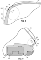
- the club head 300 can have one or more thin regions 376.
- the one or more thin regions 376 can be positioned on the strikeface 304, the body 302, or a combination of the strikeface 304 and the body 302 (see FIG. 7 ). Further, the one or more thin regions 376 can be positioned on any region of the body 302, including the crown 316, the sole 318, the heel 320, the toe 322, the front end 308, the back end 310, the skirt 328, or any combination of the described positions. For example, in some embodiments, the one or more thin regions 376 can be positioned on the crown 316. For further example, the one or more thin regions 376 can be positioned on a combination of the strikeface 304 and the crown 306.
- the one or more thin regions 376 can be positioned on a combination of the strikeface 304, the crown 316, and the sole 318.
- the entire body 302 and/or the entire strikeface 304 can comprise a thin region 376.
- the thickness of the strikeface 304 can vary defining a maximum strikeface thickness and a minimum strikeface thickness.
- the minimum strikeface thickness can be less than 2.5 mm (0.10 inches), less than 2.3 mm (0.09 inches), less than 2.0 mm (0.08 inches), less than 1.8 mm (0.07 inches), less than 1.5 mm (0.06 inches), less than 1.3 mm (0.05 inches), less than 1.0 mm (0.04 inches), or less than 0.8 mm (0.03 inches).
- the maximum strikeface thickness can be less than 5.1 mm (0.20 inches), less than 4.8 mm (0.19 inches), less than 4.6 mm (0.18 inches), less than 4.3 mm (0.17 inches), less than 4.1 mm (0.16 inches), less than 3.8 mm (0.15 inches), less than 3.6 mm (0.14 inches), less than 3.3 mm (0.13 inches), less than 3.0 mm (0.12 inches), less than 2.8 mm (0.11 inches), or less than 2.5 mm (0.10 inches).
- the thin regions can comprise a thickness less than approximately 0.51 mm (0.020 inches). In other embodiments, the thin regions comprise a thickness less than 0.64 mm (0.025 inches), less than 0.51 mm (0.020 inches), less than 0.48 mm (0.019 inches), less than 0.46 mm (0.018 inches), less than 0.43 mm (0.017 inches), less than 0.41 mm (0.016 inches), less than 0.38 mm (0.015 inches), less than 0.36 mm (0.014 inches), less than 0.33 mm (0.013 inches), less than 0.30 mm (0.012 inches), or less than 0.25 mm (0.010 inches).
- the thin regions can comprise a thickness between approximately 0.25 - 0.64 mm (0.010 - 0.025 inches), between approximately 0.33 - 0.51 mm (0.013 - 0.020 inches), between approximately 0.36 - 0.51 mm (0.014 - 0.020 inches), between approximately 0.38 - 0.51 mm (0.015 - 0.020 inches), between approximately 0.41 - 0.51 mm (0.016 - 0.020 inches), between approximately 0.43 - 0.51 mm (0.017 - 0.020 inches), or between approximately 0.46 - 0.51 mm (0.018 - 0.020 inches).
- the thin regions 376 vary in shape and position and cover approximately 25% of the surface area of club head 300. In other embodiments, the thin regions can cover approximately 20-30%, approximately 15-35%, approximately 15-25%, approximately 10-25%, approximately 15-30%, or approximately 20-50% of the surface area of club head 900. Further, in other embodiments, the thin regions can cover up to 5%, up to 10%, up to 15%, up to 20%, up to 25%, up to 30%, up to 35%, up to 40%, up to 45%, or up to 50% of the surface area of club head 300.
- the crown 316 can comprise one or more thin regions 376, such that approximately 51% of the surface area of the crown 316 comprises thin regions 376. In other embodiments, the crown 316 can comprise one or more thin regions 376, such that up to 20%, up to 25%, up to 30%, up to 35%, up to 40%, up to 45%, up to 50%, up to 55%, up to 60%, up to 65%, up to 70%, up to 75%, up to 80%, up to 85%, or up to 90% of the crown 316 comprises thin regions 376. For example, in some embodiments, approximately 40-60% of the crown 316 can comprise thin regions 376.
- approximately 50-100%, approximately 40-80%, approximately 35-65%, approximately 30-70%, or approximately 25-75% of the crown 316 can comprise thin regions 376.
- the crown 316 can comprise one or more thin regions 376, wherein each of the one or more thin regions 376 become thinner in a gradient fashion.
- the one or more thin regions 376 of the crown 316 extend in a heel-to-toe direction, and each of the one or more thin regions 376 decrease in thickness in a direction from the strikeface 304 toward the back end 310.
- the sole 318 can comprise one or more thin regions 376, such that approximately 64% of the surface area of the sole 318 comprises thin regions 376.
- the sole 318 can comprise one or more thin regions 376, such that up to 20%, up to 25%, up to 30%, up to 35%, up to 40%, up to 45%, up to 50%, up to 55%, up to 60%, up to 65%, up to 70%, up to 75%, up to 80%, up to 85%, or up to 90% of the sole 318 comprises thin regions 376.
- approximately 40-60% of the sole 318 can comprise thin regions 376.
- approximately 50-100%, approximately 40-80%, approximately 35-65%, approximately 30-70%, or approximately 25-75% of the sole 318 can comprise thin regions 376.
- the thinned regions 376 can comprise any shape, such as circular, triangular, square, rectangular, ovular, or any other polygon or shape with at least one curved surface. Further, one or more thinned regions 376 can comprise the same shape as, or a different shape than the remaining thinned regions.
- club head 100 having thin regions can be manufacturing using centrifugal casting.
- centrifugal casting allows the club head 300 to have thinner walls than a club head manufactured using conventional casting.
- portions of the club head 300 having thin regions can be manufactured using other suitable methods, such as stamping, forging, or machining.
- the portions of the club head 300 can be coupled using epoxy, tape, welding, mechanical fasteners, or other suitable methods.
- the first material of the strikeface 304 can be an optimized material, as described in U.S Provisional Patent Appl. No 62/399,929 , entitled "Golf Club Heads with Optimized Material Properties.”
- the first material comprising an optimized titanium alloy can have a specific strength greater than or equal to approximately 900,000 PSI/lb/in 3 (224 MPa/g/cm 3 ), greater than or equal to approximately 910,000 PSI/lb/in 3 (227 MPa/g/cm 3 ), greater than or equal to approximately 920,000 PSI/lb/in 3 (229 MPa/g/cm 3 ), greater than or equal to approximately 930,000 PSI/lb/in 3 (232 MPa/g/cm 3 ), greater than or equal to approximately 940,000 PSI/lb/in 3 (234 MPa/g/cm 3 ), greater than or equal to approximately 950,000 PSI/lb/in 3 (237 MPa/g/cm 3 ), greater than or equal to approximately
- the first material comprising an optimized titanium alloy can have a specific flexibility greater than or equal to approximately 0.0075, greater than or equal to approximately 0.0080, greater than or equal to approximately 0.0085, greater than or equal to approximately 0.0090, greater than or equal to approximately 0.0091, greater than or equal to approximately 0.0092, greater than or equal to approximately 0.0093, greater than or equal to approximately 0.0094, greater than or equal to approximately 0.0095, greater than or equal to approximately 0.0096, greater than or equal to approximately 0.0097, greater than or equal to approximately 0.0098, greater than or equal to approximately 0.0099, greater than or equal to approximately 0.0100, greater than or equal to approximately 0.0105, greater than or equal to approximately 0.0110, greater than or equal to approximately 0.0115, or greater than or equal to approximately 0.0120.
- the first material comprising an optimized steel alloy can have a specific strength greater than or equal to approximately 650,000 PSI/lb/in 3 (162 MPa/g/cm 3 ), greater than or equal to approximately 700,000 PSI/lb/in 3 (174 MPa/g/cm 3 ), greater than or equal to approximately 750,000 PSI/lb/in 3 (187 MPa/g/cm 3 ), greater than or equal to approximately 800,000 PSI/lb/in 3 (199 MPa/g/cm 3 ), greater than or equal to approximately 810,000 PSI/lb/in 3 (202 MPa/g/cm 3 ), greater than or equal to approximately 820,000 PSI/lb/in 3 (204 MPa/g/cm 3 ), greater than or equal to approximately 830,000 PSI/lb/in 3 (207 MPa/g/cm 3 ), greater than or equal to approximately 840,000 PSI/lb/in 3 (209 MPa/g/cm 3 ), greater than or equal to approximately 840,000 PSI/lb
- the first material comprising an optimized steel alloy can have a specific flexibility greater than or equal to approximately 0.0060, greater than or equal to approximately 0.0065, greater than or equal to approximately 0.0070, greater than or equal to approximately 0.0075, greater than or equal to approximately 0.0080, greater than or equal to approximately 0.0085, greater than or equal to approximately 0.0090, greater than or equal to approximately 0.0095, greater than or equal to approximately 0.0100, greater than or equal to approximately 0.0105, greater than or equal to approximately 0.0110, greater than or equal to approximately 0.0115, greater than or equal to approximately 0.0120, greater than or equal to approximately 0.0125, greater than or equal to approximately 0.0130, greater than or equal to approximately 0.0135, greater than or equal to approximately 0.0140, greater than or equal to approximately 0.0145, or greater than or equal to approximately 0.0150.
- the increased specific strength and/or increased specific flexibility of the optimized first material allow the strikeface 304, or portions thereof, to be thinned, as described above, while maintaining durability. Thinning of the strikeface 304 can reduce the weight of the strikeface, thereby increasing discretionary weight to be strategically positioned in other areas of the club head 300 to position the head CG low and back and/or increase the club head moment of inertia.
- the second material of the body 302 can be an optimized material, as described in U.S Provisional Patent Appl. No. 62/399,929 , entitled "Golf Club Heads with Optimized Material Properties.”
- the second material comprising an optimized titanium alloy can have a specific strength greater than or equal to approximately 730,500 PSI/lb/in 3 (182 MPa/g/cm 3 ).
- the specific strength of the optimized titanium alloy can be greater than or equal to approximately 650,000 PSI/lb/in 3 (162 MPa/g/cm 3 ), greater than or equal to approximately 700,000 PSI/lb/in 3 (174 MPa/g/cm 3 ), greater than or equal to approximately 750,000 PSI/lb/in 3 (187 MPa/g/cm 3 ), greater than or equal to approximately 800,000 PSI/lb/in 3 (199 MPa/g/cm 3 ), greater than or equal to approximately 850,000 PSI/lb/in 3 (212 MPa/g/cm 3 ), greater than or equal to approximately 900,000 PSI/lb/in 3 (224 MPa/g/cm 3 ), greater than or equal to approximately 950,000 PSI/lb/in 3 (237 MPa/g/cm 3 ), greater than or equal to approximately 1,000,000 PSI/lb/in 3 (249 MPa/g/cm 3 ), greater than or equal to approximately 1,050,000 PSI/lb/in
- the second material comprising an optimized titanium alloy can have a specific flexibility greater than or equal to approximately 0.0060, greater than or equal to approximately 0.0065, greater than or equal to approximately 0.0070, greater than or equal to approximately 0.0075, greater than or equal to approximately 0.0080, greater than or equal to approximately 0.0085, greater than or equal to approximately 0.0090, greater than or equal to approximately 0.0095, greater than or equal to approximately 0.0100, greater than or equal to approximately 0.0105, greater than or equal to approximately 0.0110, greater than or equal to approximately 0.0115, or greater than or equal to approximately 0.0120.
- the second material comprising an optimized steel can have a specific strength greater than or equal to approximately 500,000 PSI/lb/in 3 (125 MPa/g/cm 3 ), greater than or equal to approximately 510,000 PSI/lb/in 3 (127 MPa/g/cm 3 ), greater than or equal to approximately 520,000 PSI/lb/in 3 (130 MPa/g/cm 3 ), greater than or equal to approximately 530,000 PSI/lb/in 3 (132 MPa/g/cm 3 ), greater than or equal to approximately 540,000 PSI/lb/in 3 (135 MPa/g/cm 3 ), greater than or equal to approximately 550,000 PSI/lb/in 3 (137 MPa/g/cm 3 ), greater than or equal to approximately 560,000 PSI/lb/in 3 (139 MPa/g/cm 3 ), greater than or equal to approximately 570,000 PSI/lb/in 3 (142 MPa/g/cm 3 ), greater than or equal to approximately 580,000 PSI
- the second material comprising an optimized steel can have a specific flexibility greater than or equal to approximately 0.0060, greater than or equal to approximately 0.0062, greater than or equal to approximately 0.0064, greater than or equal to approximately 0.0066, greater than or equal to approximately 0.0068, greater than or equal to approximately 0.0070, greater than or equal to approximately 0.0072, greater than or equal to approximately 0.0076, greater than or equal to approximately 0.0080, greater than or equal to approximately 0.0084, greater than or equal to approximately 0.0088, greater than or equal to approximately 0.0092, greater than or equal to approximately 0.0096, greater than or equal to approximately 0.0100, greater than or equal to approximately 0.0105, greater than or equal to approximately 0.0110, greater than or equal to approximately 0.0115, greater than or equal to approximately 0.0120, greater than or equal to approximately 0.0125, greater than or equal to approximately 0.0130, greater than or equal to approximately 0.0135, greater than or equal to approximately 0.0140, greater than or equal to approximately 0.0145, or greater
- the increased specific strength and/or increased specific flexibility of the optimized second material allow the body 302, or portions thereof, to be thinned, while maintaining durability. Thinning of the body can reduce club head weight, thereby increasing discretionary weight to be strategically positioned in other areas of the club head 300 to position the head CG low and back and/or increase the club head moment of inertia.
- the club head 300 can include one or more weight structures 380 comprising one or more removable weights 382.
- the one or more weight structures 380 and/or the one or more removable weights 382 can be located towards the sole 318 and towards the back end 310, thereby positioning the discretionary weight on the sole 318 and near the back end 310 of the club head 300 to achieve a low and back head CG position.
- the one or more weight structures 380 removably receive the one or more removable weights 382.
- the weight center 387 of the one or more embedded weights 383 is positioned at a distance from the head CG 370 greater than 56 mm (2.2 inches), greater than 58 mm (2.3 inches), greater than 61 mm (2.4 inches), greater than 64 mm (2.5 inches), greater than 66 mm (2.6 inches), greater than 69 mm (2.7 inches), greater than 71 mm (2.8 inches), greater than 74 mm (2.9 inches), or greater than 76 mm (3.0 inches).
- the one or more embedded weights 383 can comprise a material having a specific gravity between 10.0 - 22.0.
- the one or more embedded weights 383 can comprise a material having a specific gravity greater than 10.0, greater than 11.0, greater than 12.0, greater than 13.0, greater than 14.0, greater than 15.0, greater than 16.0, greater than 17.0, greater than 18.0, or greater than 19.0.
- each of the embedded weights can comprise the same or a different material.
- the golf club head 300 can further include a steep crown angle 388 to achieve the low and back head CG position.
- the steep crown angle 388 positions the back end of the crown 316 toward the sole 318 or ground, thereby lowering the club head CG position.
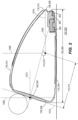
- the crown angle 388 is measured as the acute angle between a crown axis 1090 and the front plane 1020.
- the crown axis 1090 is located in a cross-section of the club head taken along a plane positioned perpendicular to the ground plane 1030 and the front plane 1020.
- the crown axis 1090 can be further described with reference to a top transition boundary and a rear transition boundary.
- the club head 300 includes a top transition boundary extending between the front end 308 and the crown 316 from near the heel 320 to near the toe 322.
- the top transition boundary includes a crown transition profile 390 when viewed from a side cross sectional view taken along a plane perpendicular to the front plane 1020 and perpendicular to the ground plane 1030 when the club head 300 is at an address position.
- the side cross sectional view can be taken along any point of the club head 300 from near the heel 320 to near the toe 322.
- the crown transition profile 390 defines a front radius of curvature 392 extending from the front end 308 of the club head 300 where the contour departs from the roll radius and/or the bulge radius of the strikeface 304 to a crown transition point 394 indicating a change in curvature from the front radius of curvature 392 to the curvature of the crown 316.
- the front radius of curvature 392 comprises a single radius of curvature extending from the top end 393 of the strikeface perimeter 342 near the crown 316 where the contour departs from the roll radius and/or the bulge radius of the strikeface 304 to a crown transition point 394 indicating a change in curvature from the front radius of curvature 392 to one or more different curvatures of the crown 316.
- the club head 300 further includes a rear transition boundary extending between the crown 316 and the skirt 328 from near the heel 320 to near the toe 322.
- the rear transition boundary includes a rear transition profile 396 when viewed from a side cross sectional view taken along a plane perpendicular to the front plane 1020 and perpendicular to the ground plane 1030 when the club head 300 is at an address position.
- the cross sectional view can be taken along any point of the club head 300 from near the heel 320 to near the toe 322.
- the rear transition profile 396 defines a rear radius of curvature 398 extending from the crown 316 to the skirt 328 of the club head 300.
- the rear radius of curvature 398 comprises a single radius of curvature that transitions the crown 316 to the skirt 328 of the club head 300 along the rear transition boundary.
- a first rear transition point 402 is located at the junction between the crown 316 and the rear transition boundary.
- a second rear transition point 403 is located at the junction between the rear transition boundary and the skirt 328 of the club head 300.
- the front radius of curvature 392 of the top transition boundary can remain constant, or can vary from near the heel 320 to near the toe 322 of the club head 300.
- the rear radius of curvature 398 of the rear transition boundary can remain constant, or can vary from near the heel 320 to near the toe 322 of the club head 300.
- the crown axis 1090 extends between the crown transition point 394 near the front end 308 of the club head 300 and the rear transition point 402 near the back end 310 of the club head 300.
- the crown angle 388 can remain constant, or can vary from near the heel 320 to near the toe 322 of the club head 300.
- the crown angle 388 can vary when the side cross sectional view is taken at different locations relative to the heel 320 and the toe 322.
- the crown angle 388 near the toe 322 is approximately 72.25 degrees
- the crown angle 388 near the heel 320 is approximately 64.5 degrees
- the crown angle 388 near the center of the golf club head is approximately 64.2 degrees.
- the maximum crown angle 388 taken at any location from near the toe 322 to near the heel 320 is less than 79 degrees, less than approximately 78 degrees, less than approximately 77 degrees, less than approximately 76 degrees, less than approximately 75 degrees, less than approximately 74 degrees, less than approximately 73 degrees, less than approximately 72 degrees, less than approximately 71 degrees, less than approximately 70 degrees, less than approximately 69 degrees, or less than approximately 68 degrees.
- the maximum crown angle is between 50 degrees and 79 degrees, between 60 degrees and 79 degrees, or between 70 degrees and 79 degrees.
- the crown 388 angle near the toe 322 of the club head 300 can be less than approximately 79 degrees, less than approximately 78 degrees, less than approximately 77 degrees, less than approximately 76 degrees, less than approximately 75 degrees, less than approximately 74 degrees, less than approximately 73 degrees, less than approximately 72 degrees, less than approximately 71 degrees, less than approximately 70 degrees, less than approximately 69 degrees, or less than approximately 68 degrees.
- the crown angle 388 taken along a side cross sectional view positioned approximately 25 mm (1.0 inch) toward the toe 322 from the geometric center 340 of the strikeface 304 can be less than 79 degrees, less than 78 degrees, less than 77 degrees, less than 76 degrees, less than 75 degrees, less than 74 degrees, less than 73 degrees, less than 72 degrees, less than 71 degrees, less than 70 degrees, less than 69 degrees, or less than 68 degrees.
- the crown angle 388 near the heel 320 can be less than approximately 70 degrees, less than approximately 69 degrees, less than approximately 68 degrees, less than approximately 67 degrees, less than approximately 66 degrees, less than approximately 65 degrees, less than approximately 64 degrees, less than approximately 63 degrees, less than approximately 62 degrees, less than approximately 61 degrees, less than approximately 60 degrees, less than approximately 59 degrees.
- the crown angle 388 taken along a side cross sectional view positioned approximately 25 mm (1.0 inch) toward the heel 320 from the geometric center 340 of the strikeface 304 can be less than approximately 70 degrees, less than approximately 69 degrees, less than approximately 68 degrees, less than approximately 67 degrees, less than approximately 66 degrees, less than approximately 65 degrees, less than approximately 64 degrees, less than approximately 63 degrees, less than approximately 62 degrees, less than approximately 61 degrees, less than approximately 60 degrees, less than approximately 59 degrees.
- the crown angle 388 near the center of the club head 300 can be less than 75 degrees, less than 74 degrees, less than 73 degrees, less than 72 degrees, less than 71 degrees, less than approximately 70 degrees, less than approximately 69 degrees, less than approximately 68 degrees, less than approximately 67 degrees, less than approximately 66 degrees, less than approximately 65 degrees, less than approximately 64 degrees, less than approximately 63 degrees, less than approximately 62 degrees, less than approximately 61 degrees, less than approximately 60 degrees, less than approximately 59 degrees.
- the crown angle 388 taken along a side cross sectional view positioned approximately at the geometric center 340 of the strikeface 304 can be less than approximately 70 degrees, less than approximately 69 degrees, less than approximately 68 degrees, less than approximately 67 degrees, less than approximately 66 degrees, less than approximately 65 degrees, less than approximately 64 degrees, less than approximately 63 degrees, less than approximately 62 degrees, less than approximately 61 degrees, less than approximately 60 degrees, less than approximately 59 degrees.
- reducing the crown angle 388 compared to current club heads generates a steeper crown or a crown positioned closer to the ground plane 1030 when the club head 300 is at an address position. Accordingly, the reduced crown angle 388 can result in a lower head CG position compared to a club head with a higher crown angle.
- the head CG height 174 and/or head CG depth 172 can be achieved by reducing the mass of the hosel sleeve 334. Removing excess weight from the hosel sleeve 334 results in increased discretionary weight that can be strategically repositioned to regions of the club head 300 to achieve the desired low and back club head CG position.
- Reducing the mass of the hosel sleeve 334 can be achieved by thinning the sleeve walls, reducing the height of the hosel sleeve 334, reducing the diameter of the hosel sleeve 334, and/or by introducing voids in the walls of the hosel sleeve 334.
- the mass of the hosel sleeve 334 can be less than 6 grams, less than 5.5 grams, less than 5.0 grams, less than 4.5 grams, or less than 4.0 grams.
- the club head 300 having the reduced mass hosel sleeve can result in a lower (close to the sole) and farther back (closer to the back end) club head CG position than a similar club head with a heavier hosel sleeve.
- the club head 300 comprises a low and back club head CG position and an increased club head moment of inertia, in combination with reduced aerodynamic drag.
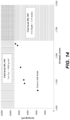
- the club head 300 experiences an aerodynamic drag force less than approximately 6.7 N (1.5 lbf). In some embodiments, the club head 300 experiences an aerodynamic draft force approximately less than 6.2 N (1.4 lbf), less than 5.8 N (1.3 lbf), or less than 5.3 N (1.2 lbf) when tested in a wind tunnel with a squared face and an air speed of 164 kilometers per hour (km/h) (102 miles per hour (mph)).
- the club head 300 experiences an aerodynamic drag force less than approximately less than 6.2 N (1.4 lbf), less than 5.8 N (1.3 lbf), or less than 5.3 N (1.2 lbf) when simulated using computational fluid dynamics with a squared face and an air speed of 164 km/h (102 miles per hour (mph)), or in some examples useful for understanding the invention less than approximately 6.7 N (1.5 lbf).
- the airflow experienced by the club head 300 having the squared face is directed at the strikeface 304 in a direction perpendicular to the X'Y' plane.
- the club head 300 having reduced aerodynamic drag can be achieved using various means, as described below.
- reducing the crown angle 388 to form a steeper crown and lower head CG position may result in an undesired increase in aerodynamic drag due to increased air flow separation over the crown during a swing.
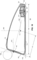
- a maximum crown height 404 can be increased. Referring to FIG. 4 , the maximum crown height 404 is the greatest distance between the surface of the crown 316 and the crown axis 1090 taken at any side cross sectional view of the club head 300 along a plane positioned parallel to the Y'Z' plane. In many embodiments, a greater maximum crown height 404 results in the crown 316 having a greater curvature.
- a greater curvature in the crown 316 moves the location of the air flow separation during a swing further back on the club head 300.
- a greater curvature allows the airflow to stay attached to club head 300 for a longer distance along the crown 316 during a swing. Moving the airflow separation point back on the crown 316 can result in reduced aerodynamic drag and increased club head swing speeds, thereby resulting in increased ball speed and distance.
- the maximum crown height 404 can be greater than approximately 0.20 inch (5mm), greater than approximately 0.30 inch (7.5mm), greater than approximately 0.40 inch (10mm), greater than approximately 0.50 inch (12.5mm), greater than approximately 0.60 inch (15mm), greater than approximately 0.70 inch (17.5mm), greater than approximately 0.80 inch (20mm), greater than approximately 0.90 inch (22.5mm), or greater than approximately 1.0 inch (25mm). Further, in other embodiments, the maximum crown height can be within the range of 0.20 inch (5mm) to 0.60 inch (15mm), or 0.40 inch (10mm) to 0.80 inch (20mm), or 0.60 inch (15mm) to 1.0 inch (25mm). For example, in some embodiments, the maximum crown height 404 can be approximately 0.52 inch (13.3mm), approximately 0.54 inch (13.8mm), approximately 0.59 inch (15mm), approximately 0.65 inch (16.5mm), or approximately 0.79 inch (20mm).
- the transition profiles of the club head 300 from the strikeface 304 to the crown 316, the strikeface 304 to the sole 318, and/or the crown 316 to the sole 318 along the back end 310 of the club head 300 can affect the aerodynamic drag on the club head 300 during a swing.
- the club head 300 having the top transition boundary defining the crown transition profile 390, and the rear transition boundary defining the rear transition profile 396 further includes a sole transition boundary defining a sole transition profile 410.
- the sole transition boundary extends between the front end 308 and the sole 318 from near the heel 320 to near the toe 322.
- the sole transition boundary includes a sole transition profile 410 when viewed from a side cross sectional view taken along a plane parallel to the Y'Z' plane. The side cross sectional view can be taken along any point of the club head 300 from near the heel 320 to near the toe 322.
- the sole transition profile 410 defines a sole radius of curvature 412 extending from the front end 308 of the club head 300 where the contour departs from the roll radius and/or the bulge radius of the strikeface 304 to a sole transition point 414 indicating a change in curvature from sole radius of curvature 412 to the curvature of the sole 318.
- the sole radius of curvature 412 comprises a single radius of curvature extending from the bottom end 413 of the strikeface perimeter 342 near the sole 318 where the contour departs from the roll radius and/or the bulge radius of the strikeface 304 to a sole transition point 414 indicating a change in curvature from the sole radius of curvature 412 to a curvature of the sole 414.
- the crown transition profile 390, the sole transition profile 410, and the rear transition profile 396 can be similar to the crown transition, sole transition, and rear transition profiles described in U.S. Patent No. 15/233,486 , entitled “Golf Club Head with Transition Profiles to Reduce Aerodynamic Drag.”
- the front radius of curvature 392 can be similar to the first crown radius of curvature
- the sole radius of curvature 412 can be similar to the first sole radius of curvature
- the rear radius of curvature 398 can be similar to the rear radius of curvature described U.S. Patent No. 15/233,486 , entitled “Golf Club Head with Transition Profiles to Reduce Aerodynamic Drag.”
- front radius of curvature 392 can range from approximately 0.18 to 0.30 inches (0.46 to 0.76 cm). Further, in some examples useful for understanding the invention, the front radius of curvature 392 can be less than 0.40 inches (1.02 cm), less than 0.375 inches (0.95 cm), less than 0.35 inches (0.89 cm), less than 0.325 inches (0.83 cm), and in some embodiments the front radius of curvature 392 can be less than 0.30 inches 0.76 cm). For example, the front radius of curvature 392 may be approximately 0.18 inches (0.46 cm), 0.20 inches (0.51 cm), 0.22 inches (0.66 cm), 0.24 inches (0.61 cm), 0.26 inches (0.66 cm), 0.28 inches (0.71 cm), or 0.30 inches (0.76 cm).
- the sole radius of curvature 412 can range from approximately 0.25 to 0.50 inches (0.76 to 1.27 cm).
- the sole radius of curvature 412 can be less than approximately 0.5 inches (1.27 cm), less than approximately 0.475 inches (1.21 cm), less than approximately 0.45 inches (1.14 cm), less than approximately 0.425 inches (1.08 cm), or less than approximately 0.40 inches (1.02 cm).
- the sole radius of curvature 412 can be approximately 0.30 inches (0.76 cm), 0.35 inches (0.89 cm), 0.40 inches (1.02 cm), 0.45 inches (1.14 cm), or 0.50 inches (1.27 cm).
- the rear radius of curvature 398 can range from approximately 0.10 to 0.25 inches (0.25 to 0.64 cm).
- the rear radius of curvature 398 can be less than approximately 0.3 inches (0.76 cm), less than approximately 0.275 inches (0.70 cm), less than approximately 0.25 inches (0.64 cm), less than approximately 0.225 inches (0.57 cm), or less than approximately 0.20 inches (0.51 cm).
- the rear radius of curvature 398 can be approximately 0.10 inches (0.25 cm), 0.15 inches (0.38 cm), 0.20 inches (0.51 cm), or 0.25 inches (0.64 cm).
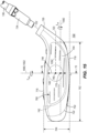
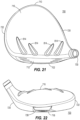
- the club head 300 can further include a plurality of turbulators 414, as described in U.S. Patent Appl. No. 13/536,753 , now U.S. Patent No. 8,608,587, granted on December 17, 2013 , entitled "Golf Club Heads with Turbulators and Methods to Manufacture Golf Club Heads with Turbulators,".
- the plurality of turbulators 414 disrupt the airflow thereby creating small vortices or turbulence inside the boundary layer to energize the boundary layer and delay separation of the airflow on the crown 316 during a swing.
- the plurality of turbulators 414 can be adjacent to the crown transition point 594 of the club head 300.
- the plurality of turbulators 414 project from an outer surface of the crown 316 and include a length extending between the front end 308 and the back end 310 of the club head 300, and a width extending from the heel 320 to the toe 322 of the club head 300.
- the length of the plurality of turbulators 414 is greater than the width.
- the plurality of turbulators 414 can comprise the same width.
- the plurality of turbulators 414 can vary in height profile.
- the plurality of turbulators 414 can be higher toward the apex of the crown 316 than in comparison to the front of the crown 316. In other embodiments, the plurality of turbulators 414 can be higher toward the front of the crown 316, and lower in height toward the apex of the crown 316. In other embodiments, the plurality of turbulators 414 can comprise a constant height profile. Further, in many embodiments, at least a portion of at least one turbulator is located between the strikeface 304 and an apex of the crown 316, and the spacing between adjacent turbulators is greater than the width of each of the adjacent turbulators.
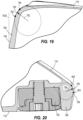
- the club head 300 can further include a cavity 420 located at the back end 310 and in the trailing edge 328 of the club head 300, similar to the cavity described in U.S. Patent Appl. No. 14/882,092 , now U.S. Patent No. 9,492,721 granted on November 15, 2016 , entitled "Golf Club Heads with Aerodynamic Features and Related Methods,".
- the cavity 420 can break the vortices generated behind golf club head 300 into smaller vortices to reduce the size of the wake and/or reduce drag. In some embodiments, breaking the vortices into smaller vortices can generate a region of high pressure behind golf club head 300.
- this region of high pressure can push golf club head 300 forward, reduce drag, and/or enhance the aerodynamic design of golf club head 300.
- the net effect of smaller vortices and reduced drag is an increase in the speed of golf club head 300. This effect can lead to higher speeds at which a golf ball leaves strikeface 304 after impact to increase ball travel distance.
- the cavity 420 includes a back wall 422 that is oriented in a direction perpendicular to the X'Z' plane and includes a width measured in a direction from the heel 320 to the toe 322, a depth 424, and a height 426.
- the width of the cavity 420 can be approximately 1.0 inches (approximately 2.54 centimeters (cm)) to approximately 8 inch (approximately 20.32 cm), approximately 1.0 inches (approximately 2.54 cm) to approximately 2.25 inches (approximately 5.72 cm), or approximately 1.75 inches (approximately 4.5 cm) to approximately 2.25 inches (approximately 5.72 cm).
- the width of the cavity 420 can be approximately 2.0 inches (5.08 cm), 3.0 inches (7.62 cm), 4.0 inches (10.16 cm), 5.0 inches (12.7 cm), 6.0 inches (15.24 cm), or 7.0 inches (17.78 cm).
- the width of the cavity 420 can remain constant from near the top of the cavity 420 (toward the crown 316 of the club head 300) to near the bottom of the cavity 420 (toward the sole 318 of the club head 300).
- the width of the cavity 420 can vary from near the top to near the bottom.
- the width of the cavity 420 is largest near the top and smallest near the bottom.
- the width of the cavity 420 can vary according to any profile.
- the width of the cavity 420 can be longest at the top, at the bottom, at the center, or at any other location extending from the top to the bottom of the cavity 420.
- the depth 424 of the cavity 420 can be approximately 0.025 inch (approximately 0.127 cm) to approximately 0.250 inch (approximately 0.635 cm), or approximately 0.025 inch (approximately 0.127 cm) to approximately 0.150 inch (approximately 0.381 cm).
- the depth 424 of the cavity 420 can be approximately 0.1 inch (approximately 0.254 cm), or approximately 0.05 inch (approximately 0.127 cm).
- the depth 424 of the cavity 420 can remain constant between the heel and the toe and/or between the top and the bottom of the cavity 420.
- the depth 424 of the cavity 420 can vary between the heel and the toe and/or between the top and the bottom of the cavity 420.
- the depth 424 of the cavity 420 can be the largest near the heel, near the toe, near the crown, near the sole, near the center, or at any combination of the described locations.
- the height 426 of the cavity 420 can be measured in a direction from the crown 316 to the sole 318.
- the height 426 of the cavity 420 can be approximately 0.19 inch (approximately 0.48 cm) to approximately 0.21 inch (approximately 0.53 cm).
- the height 426 of the cavity 420 can be approximately 0.10 inch (approximately 0.25 cm) to approximately 0.50 inch (approximately 1.27 cm).
- the height 426 of the cavity 420 can be approximately 0.10 inch (approximately 0.25 cm) to approximately 0.40 inch (approximately 1.02 cm).
- the height 426 of the cavity 420 can be approximately 0.10 inch (approximately 0.25 cm) to approximately 0.30 inch (approximately 0.76 cm). In some embodiments, the height 426 of the cavity 420 can be approximately 0.10 inch (approximately 0.25 cm) to approximately 0.20 inch (approximately 0.51 cm). In some embodiments, the height 426 of the cavity 420 can remain constant between the heel and the toe of the cavity 420. In other embodiments, the height 426 of the cavity 420 can vary between the heel and the toe of the cavity 420. For example, the height 426 of the cavity 420 can be the largest near the heel, near the toe, near the center, or at any combination of the described locations.
- the hosel structure 330 can have a smaller outer diameter to reduce the aerodynamic drag on the club head 300 during a swing, compared to a similar club head having a larger diameter hosel structure. In many embodiments, the hosel structure 330 has an outer diameter less than 13.84 mm (0.545 inches).
- the hosel structure 330 can have an outer diameter less than 15.2 mm (0.60 inches), less than 15.0 mm (0.59 inches), less than 14.7 mm (0.58 inches), less than 14.5 mm (0.57 inches), less than 14.2 mm (0.56 inches), less than 14.0 mm (0.55 inches), less than 13.7 mm (0.54 inches), less than 13.5 mm (0.53 inches), less than 13.2 mm (0.52 inches), less than 13.0 mm (0.51 inches), or less than 12.7 mm (0.50 inches).
- the outer diameter of the hosel structure 330 is reduced while maintaining adjustability of the loft angle and/or lie angle of the club head 300.
- the club head 300 further comprises a front projected area and a side projected area.
- the front projected area is the area of the club head 300 visible from the front view, as illustrated in FIG. 1 , and projected on the X'Y' plane.
- the side projected area is the area of the club head 300 visible from the side view and projected on the Y'Z' plane.
- the front projected area of the club head 300 can be between 0.00400 m 2 and 0.00700 m 2 .
- the front projected area of the club head is 0.00655 m 2 .
- the front projected area can be between 0.00400 m 2 and 0.00665 m 2 , between 0.00400 m 2 and 0.00675 m 2 , between 0.00400 m 2 and 0.00685 m 2 , or between 0.00400 m 2 and 0.00695 m 2 .
- the side projected area of the club head 300 can be between 0.00500 m 2 and 0.00650 m 2 .
- the front projected area of the club head is 0.00579 m 2 .
- the front projected area can be between 0.00545 m 2 and 0.00565 m 2 , between 0.00535 m 2 and 0.00575 m 2 , between 0.00525 m 2 and 0.00585 m 2 , or between 0.00515 m 2 and 0.00595 m 2 .
- the club head 300 described herein increases or maximizes the club head moment of inertia, while simultaneously maintaining or reducing aerodynamic drag, as described in further detail below. Accordingly, the club head 300 having improved impact performance characteristics (e.g. spin, launch angle, ball speed, and forgiveness) also balances or improves swing performance characteristics (e.g. aerodynamic drag, ability to square the club head at impact, and swing speed).
- impact performance characteristics e.g. spin, launch angle, ball speed, and forgiveness
- swing performance characteristics e.g. aerodynamic drag, ability to square the club head at impact, and swing speed.
- a golf club head 500 can comprise a low volume and a low loft angle.
- the golf club head 500 comprises a driver-type club head.
- the golf club head 500 can comprise any type of golf club head having a loft angle and volume as described herein.
- club head 500 comprises the same or similar parameters as club head 100, wherein the parameters are described with the club head 100 reference numbers plus 400.
- the loft angle of the club head 500 is less than approximately 16 degrees, less than approximately 15 degrees, less than approximately 14 degrees, less than approximately 13 degrees, less than approximately 12 degrees, less than approximately 11 degrees, or less than approximately 10 degrees. Further, in many embodiments, the volume of the club head 500 is less than approximately 450 cc, less than approximately 440 cc, less than approximately 430 cc, less than approximately 425 cc, less than approximately 400 cc, less than approximately 375 cc, or less than approximately 350 cc.
- the volume of the club head can be approximately 300cc - 450cc, approximately 300cc - 400cc, approximately 325cc - 425cc, approximately 350cc - 450cc, approximately 400cc - 450cc, approximately 420cc - 450 cc, or approximately 440cc - 450cc.
- the length 562 of the club head 500 is greater than 123.2 mm (4.85 inches). In other embodiments, the length 562 of the club head 500 is greater than 114 mm (4.5 inches), greater than 117 mm (4.6 inches), greater than 119 mm (4.7 inches), greater than 122 mm (4.8 inches), greater than 124 mm (4.9 inches), or greater than 127 mm (5.0 inches).
- the length 562 of the club head 500 can be between 117 - 127 mm (4.6 - 5.0 inches), between 119 - 127 mm (4.7 - 5.0 inches), between 122 - 127 mm (4.8 - 5.0 inches), between 123.2 - 127 mm (4.85 - 5.0 inches), or between 124 - 127 mm (4.9 - 5.0 inches).
- the depth 560 of the club head 500 is at least 17.8 mm (0.70) inches less than the length 562 of the club head 500. In many embodiments, the depth 560 of the club head 500 is greater than 120.7 mm (4.75 inches). In other embodiments, the depth 360 of the club head 500 is greater than 114 mm (4.5 inches), greater than 117 mm (4.6 inches), greater than 119 mm (4.7 inches), greater than 122 mm (4.8 inches), greater than 124 mm (4.9 inches), or greater than 127 mm (5.0 inches).
- the depth 560 of the club head 500 can be between 117 - 127 mm (4.6 - 5.0 inches), between 119 - 127 mm (4.7 - 5.0 inches), between 120.7 - 127 mm (4.75 - 5.0 inches), between 122 - 127 mm (4.8 - 5.0 inches), or between 124 - 127 mm (4.9 - 5.0 inches).
- the height 564 of the club head is less than approximately 71 mm (2.8 inches). In other embodiments, the height 564 of the club head 500 is less than 76 mm (3.0 inches), less than 74 mm (2.9 inches), less than 71 mm (2.8 inches), less than 69 mm (2.7 inches), or less than 66 mm (2.6 inches).
- the height 564 of the club head 500 can be between 51 - 71 mm (2.0 - 2.8 inches), between 56 - 71 mm (2.2 - 2.8 inches), between 64 - 71 mm (2.5 - 2.8 inches), or between 64 - 76 mm (2.5 - 3.0 inches).
- the face height 544 of the club head 500 can be approximately 1.3 inches (33 mm) to approximately 2.8 inches (71 mm). Further still, in many embodiments, the club head 500 can comprise a mass between 185 grams and 225 grams.
- the club head 500 further comprises a balance of various additional parameters, such as head CG position, club head moment of inertia, and aerodynamic drag, to provide both improved impact performance characteristics (e.g. spin, launch angle, speed, forgiveness) and swing performance characteristics (e.g. aerodynamic drag, ability to square the club head at impact).
- improved impact performance characteristics e.g. spin, launch angle, speed, forgiveness
- swing performance characteristics e.g. aerodynamic drag, ability to square the club head at impact.
- the balance of parameters described below provides improved impact performance while maintaining or improving swing performance characteristics.
- the balance of parameters described below provides improved swing performance characteristics while maintaining or improving impact performance characteristics.
- a low and back club head CG and increased moment of inertia can be achieved by increasing discretionary weight and repositioning discretionary weight in regions of the club head having maximized distances from the head CG.
- Increasing discretionary weight can be achieved by thinning the crown and/or using optimized materials, as described above relative to the head CG position.
- Repositioning discretionary weight to maximize the distance from the head CG can be achieved using removable weights, embedded weights, or a steep crown angle, as described above relative to the head CG position.
- the club head 500 comprises a crown-to-sole moment of inertia I xx greater than approximately 3000 g ⁇ cm 2 , greater than approximately 3250 g ⁇ cm 2 , greater than approximately 3500 g ⁇ cm 2 , greater than approximately 3750 g ⁇ cm 2 , greater than approximately 4000 g ⁇ cm 2 , greater than approximately 4250 g ⁇ cm 2 , greater than approximately 4500 g ⁇ cm 2 , greater than approximately 4750 g ⁇ cm 2 , greater than approximately 5000 g ⁇ cm 2 , greater than approximately 5250 g ⁇ cm 2 , greater than approximately 5500 g ⁇ cm 2 , greater than approximately 5750 g ⁇ cm 2 , greater than approximately 6000 g ⁇ cm 2 , greater than approximately 6250 g ⁇ cm 2 , greater than approximately 6500 g ⁇ cm 2 , greater than approximately 6750 g ⁇ cm 2 , or greater than approximately 7000 g ⁇ cm 2 .
- the club head 500 comprises a heel-to-toe moment of inertia I yy greater than approximately 5000 g ⁇ cm 2 , greater than approximately 5250 g ⁇ cm 2 , greater than approximately 5500 g ⁇ cm 2 , greater than approximately 5750 g ⁇ cm 2 , greater than approximately 6000 g ⁇ cm 2 , greater than approximately 6250 g ⁇ cm 2 , greater than approximately 6500 g ⁇ cm 2 , greater than approximately 6750 g ⁇ cm 2 , or greater than approximately 7000 g ⁇ cm 2 .
- the club head 500 comprises a combined moment of inertia (i.e. the sum of the crown-to-sole moment of inertia I xx and the heel-to-toe moment of inertia I yy ) greater than 8000 g ⁇ cm 2 , greater than 8500 g ⁇ cm 2 , greater than 8750 g ⁇ cm 2 , greater than 9000 g ⁇ cm 2 , greater than 9250 g ⁇ cm 2 , greater than 9500 g ⁇ cm 2 , greater than 9750 g ⁇ cm 2 , greater than 10000 g ⁇ cm 2 , greater than 10250 g ⁇ cm 2 , greater than 10500 g ⁇ cm 2 , greater than 10750 g ⁇ cm 2 , greater than 11000 g ⁇ cm 2 , greater than 11250 g ⁇ cm 2 , greater than 11500 g ⁇ cm 2 , greater than 11750 g ⁇ cm 2 , or greater than 12000 g ⁇ cm
- the club head 500 comprises a head CG height 574 less than approximately 5.1 mm (0.20 inches), less than approximately 3.8 mm (0.15 inches), less than approximately 2.5 mm (0.10 inches), less than approximately 2.3 mm (0.09 inches), less than approximately 2.0 mm (0.08 inches), less than approximately 1.8 mm (0.07 inches), less than approximately 1.5 mm (0.06 inches), or less than approximately 1.3 mm (0.05 inches).
- the club head 500 comprises a head CG height 574 having an absolute value less than approximately 5.1 mm (0.20 inches), less than approximately 3.8 mm (0.15 inches), less than approximately 2.5 mm (0.10 inches), less than approximately 2.3 mm (0.09 inches), less than approximately 2.0 mm (0.08 inches), less than approximately 1.8 mm (0.07 inches), less than approximately 1.5 mm (0.06 inches), or less than approximately 1.3 mm (0.05 inches).
- the club head 500 comprises a head CG depth 572 greater than approximately 30 mm (1.2 inches), greater than approximately 33 mm (1.3 inches), greater than approximately 36 mm (1.4 inches), greater than approximately 38 mm (1.5 inches), greater than approximately 41 mm (1.6 inches), greater than approximately 43 mm (1.7 inches), greater than approximately 46 mm (1.8 inches), greater than approximately 48 mm (1.9 inches), or greater than approximately 51 mm (2.0 inches).
- the club head 500 can comprise a first performance characteristic less than or equal to 0.56, wherein the first performance characteristic is defined as a ratio between (a) the difference between 72 mm and the face height 544, and (b) the head CG depth 572.
- the club head 500 can comprise a second performance characteristic greater than or equal to 425cc, wherein the second performance characteristic is defined as the sum of (a) the volume of the club head 500, and (b) a ratio between the head CG depth 572 and the absolute value of the head CG height 574.
- the second performance characteristic can be greater than or equal to 450cc, greater than or equal to 475cc, greater than or equal to 490cc, greater than or equal to 495cc, greater than or equal to 500cc, greater than or equal to 505cc, or greater than or equal to 510cc.
- the club head 500 having the reduced head CG height 574 can reduce the backspin of a golf ball on impact compared to a similar club head having a higher head CG height. In many embodiments, reduced backspin can increase both ball speed and travel distance for improve club head performance. Further, the club head 500 having the increased head CG depth 572 can increase the heel-to-toe moment of inertia compared to a similar club head having a head CG depth closer to the strikeface. Increasing the heel-to-toe moment of inertia can increase club head forgiveness on impact to improve club head performance. Further still, the club head 500 having the increased head CG depth 572 can increase launch angle of a golf ball on impact by increasing the dynamic loft of the club head at delivery, compared to a similar club head having a head CG depth closer to the strikeface.
- the head CG height 574 and/or head CG depth 572 can be achieved by reducing weight of the club head 500 in various regions, thereby increasing discretionary weight, and repositioning discretionary weight in strategic regions of the club head to shift the head CG lower and farther back.
- Various means to reduce and reposition club head weight are described below.
- the head CG height 574 and/or head CG depth 572 can be achieved by thinning various regions of the club head 500 to remove excess weight. Removing excess weight results in increased discretionary weight that can be strategically repositioned to regions of the club head 500 to achieve the desired low and back club head CG position.
- the club head 500 can have one or more thin regions.
- the thinned regions can be similar or identical to the one or more thin regions 376 of club head 300.
- the one or more thin regions can be positioned on the strikeface 504, the body 502, or a combination of the strikeface 504 and the body 502. Further, the one or more thin regions can be positioned on any region of the body 502, including the crown 516, the sole 518, the heel 520, the toe 522, the front end 508, the back end 510, the skirt 528, or any combination of the described positions.
- the one or more thin regions can be positioned on the crown 516.
- the one or more thin regions can be positioned on a combination of the strikeface 504 and the crown 516.
- the one or more thin regions can be positioned on a combination of the strikeface 504, the crown 516, and the sole 518.
- the entire body 502 and/or the entire strikeface 504 can comprise a thin region.
- the thickness of the strikeface 504 can vary defining a maximum strikeface thickness and a minimum strikeface thickness.
- the minimum strikeface thickness can be less than 2.5 mm (0.10 inches), less than 2.3 mm (0.09 inches), less than 2.0 mm (0.08 inches), less than 1.8 mm (0.07 inches), less than 1.5 mm (0.06 inches), less than 1.3 mm (0.05 inches), less than 1.0 mm (0.04 inches), or less than 0.8 mm (0.03 inches).
- the maximum strikeface thickness can be less than 5.1 mm (0.20 inches), less than 4.8 mm (0.19 inches), less than 4.6 mm (0.18 inches), less than 4.3 mm (0.17 inches), less than 4.1 mm (0.16 inches), less than 3.8 mm (0.15 inches), less than 3.6 mm (0.14 inches), less than 3.3 mm (0.13 inches), less than 3.0 mm (0.12 inches), less than 2.8 mm (0.11 inches), or less than 2.5 mm (0.10 inches).
- the thin regions can comprise a thickness less than approximately 0.51 mm (0.020 inches). In other embodiments, the thin regions comprise a thickness less than 0.64 mm (0.025 inches), less than 0.51 mm (0.020 inches), less than 0.48 mm (0.019 inches), less than 0.46 mm (0.018 inches), less than 0.43 mm (0.017 inches), less than 0.41 mm (0.016 inches), less than 0.38 mm (0.015 inches), less than 0.36 mm (0.014 inches), less than 0.33 mm (0.013 inches), less than 0.30 mm (0.012 inches), or less than 0.25 mm (0.010 inches).
- the thin regions can comprise a thickness between approximately 0.25 - 0.64 mm (0.010 - 0.025 inches), between approximately 0.33 - 0.51 mm (0.013 - 0.020 inches), between approximately 0.36 - 0.51 mm (0.014 - 0.020 inches), between approximately 0.38 mm - 0.51 mm (0.015 - 0.020 inches), between approximately 0.41 - 0.51 mm (0.016 - 0.020 inches), between approximately 0.43 - 0.51 mm (0.017 - 0.020 inches), or between approximately 0.46 - 0.51 mm (0.018 - 0.020 inches).
- the thin regions vary in shape and position and cover approximately 25% of the surface area of club head 500. In other embodiments, the thin regions can cover approximately 20-30%, approximately 15-35%, approximately 15-25%, approximately 10-25%, approximately 15-30%, or approximately 20-50% of the surface area of club head 500. Further, in other embodiments, the thin regions can cover up to 5%, up to 10%, up to 15%, up to 20%, up to 25%, up to 30%, up to 35%, up to 40%, up to 45%, or up to 50% of the surface area of club head 500.
- the crown 518 can comprise one or more thin regions, such that approximately 51% of the surface area of the crown comprises thin regions.
- the crown 516 can comprise one or more thin regions, such that up to 20%, up to 25%, up to 30%, up to 35%, up to 40%, up to 45%, up to 50%, up to 55%, up to 60%, up to 65%, up to 70%, or up to 75% of the crown comprises thin regions.
- approximately 40-60% of the crown can comprise thin regions.
- approximately 50-100%, approximately 40-80%, approximately 35-65%, approximately 30-70%, or approximately 25-75% of the crown 516 can comprise thin regions.
- the crown 516 can comprise one or more thin regions, wherein each of the one or more thin regions become thinner in a gradient fashion.
- the one or more thin regions of the crown 516 extend in a heel-to-toe direction, and each of the one or more thin regions decrease in thickness in a direction from the strikeface 504 toward the back end 510.
- the sole 518 can comprise one or more thin regions, such that approximately 64% of the surface area of the sole comprises thin regions. In other embodiments, the sole 518 can comprise one or more thin regions, such that up to 20%, up to 25%, up to 30%, up to 35%, up to 40%, up to 45%, up to 50%, up to 55%, up to 60%, up to 65%, up to 70%, up to 75%, up to 80%, up to 85%, or up to 90% of the sole comprises thin regions. For example, in some embodiments, approximately 40-60% of the sole can comprise thin regions. For further example, in other embodiments, approximately 50-100%, approximately 40-80%, approximately 35-65%, approximately 30-70%, or approximately 25-75% of the sole 518 can comprise thin regions.
- the thinned regions can comprise any shape, such as circular, triangular, square, rectangular, ovular, or any other polygon or shape with at least one curved surface. Further, one or more thinned regions can comprise the same shape as or a different shape than the remaining thinned regions.
- club head 500 having thin regions can be manufacturing using centrifugal casting.
- centrifugal casting allows the club head 500 to have thinner walls than a club head manufactured using conventional casting.
- portions of the club head 500 having thin regions can be manufactured using other suitable methods, such as stamping, forging, or machining.
- the portions of the club head 500 can be coupled using epoxy, tape, welding, mechanical fasteners, or other suitable methods.
- the strikeface 504 and/or the body 502 can comprise an optimized material having increased specific strength and/or increased specific flexibility.
- the specific flexibility is measured as a ratio of the yield strength to the elastic modulus of the optimized material. Increasing specific strength and/or specific flexibility can allow portions of the club head to be thinned, while maintaining durability.
- the first material of the strikeface 504 can be an optimized material, as described in U.S Provisional Patent Appl. No 62/399,929 , entitled "Golf Club Heads with Optimized Material Properties.”
- the first material comprising an optimized titanium alloy can have a specific strength greater than or equal to approximately 900,000 PSI/lb/in 3 (224 MPa/g/cm 3 ), greater than or equal to approximately 910,000 PSI/lb/in 3 (227 MPa/g/cm 3 ), greater than or equal to approximately 920,000 PSI/lb/in 3 (229 MPa/g/cm 3 ), greater than or equal to approximately 930,000 PSI/lb/in 3 (232 MPa/g/cm 3 ), greater than or equal to approximately 940,000 PSI/lb/in 3 (234 MPa/g/cm 3 ), greater than or equal to approximately 950,000 PSI/lb/in 3 (237 MPa/g/cm 3 ), greater than or equal to approximately
- the first material comprising an optimized titanium alloy can have a specific flexibility greater than or equal to approximately 0.0075, greater than or equal to approximately 0.0080, greater than or equal to approximately 0.0085, greater than or equal to approximately 0.0090, greater than or equal to approximately 0.0091, greater than or equal to approximately 0.0092, greater than or equal to approximately 0.0093, greater than or equal to approximately 0.0094, greater than or equal to approximately 0.0095, greater than or equal to approximately 0.0096, greater than or equal to approximately 0.0097, greater than or equal to approximately 0.0098, greater than or equal to approximately 0.0099, greater than or equal to approximately 0.0100, greater than or equal to approximately 0.0105, greater than or equal to approximately 0.0110, greater than or equal to approximately 0.0115, or greater than or equal to approximately 0.0120.
- the first material comprising an optimized steel alloy can have a specific strength greater than or equal to approximately 650,000 PSI/lb/in 3 (162 MPa/g/cm 3 ), greater than or equal to approximately 700,000 PSI/lb/in 3 (174 MPa/g/cm 3 ), greater than or equal to approximately 750,000 PSI/lb/in 3 (187 MPa/g/cm 3 ), greater than or equal to approximately 800,000 PSI/lb/in 3 (199 MPa/g/cm 3 ), greater than or equal to approximately 810,000 PSI/lb/in 3 (202 MPa/g/cm 3 ), greater than or equal to approximately 820,000 PSI/lb/in 3 (204 MPa/g/cm 3 ), greater than or equal to approximately 830,000 PSI/lb/in 3 (207 MPa/g/cm 3 ), greater than or equal to approximately 840,000 PSI/lb/in 3 (209 MPa/g/cm 3 ), greater than or equal to approximately 840,000 PSI/lb
- the first material comprising an optimized steel alloy can have a specific flexibility greater than or equal to approximately 0.0060, greater than or equal to approximately 0.0065, greater than or equal to approximately 0.0070, greater than or equal to approximately 0.0075, greater than or equal to approximately 0.0080, greater than or equal to approximately 0.0085, greater than or equal to approximately 0.0090, greater than or equal to approximately 0.0095, greater than or equal to approximately 0.0100, greater than or equal to approximately 0.0105, greater than or equal to approximately 0.0110, greater than or equal to approximately 0.0115, greater than or equal to approximately 0.0120, greater than or equal to approximately 0.0125, greater than or equal to approximately 0.0130, greater than or equal to approximately 0.0135, greater than or equal to approximately 0.0140, greater than or equal to approximately 0.0145, or greater than or equal to approximately 0.0150.
- the increased specific strength and/or increased specific flexibility of the optimized first material allow the strikeface 504, or portions thereof, to be thinned, as described above, while maintaining durability. Thinning of the strikeface 504 can reduce the weight of the strikeface 504, thereby increasing discretionary weight to be strategically positioned in other areas of the club head 500 to position the head CG low and back and/or increase the club head moment of inertia.
- the second material of the body 502 can be an optimized material, as described in U.S Provisional Patent Appl. No. 62/399,929 , entitled "Golf Club Heads with Optimized Material Properties.”
- the second material comprising an optimized titanium alloy can have a specific strength greater than or equal to approximately 730,500 PSI/lb/in 3 (182 MPa/g/cm 3 ).
- the specific strength of the optimized titanium alloy can be greater than or equal to approximately 650,000 PSI/lb/in 3 (162 MPa/g/cm 3 ), greater than or equal to approximately 700,000 PSI/lb/in 3 (174 MPa/g/cm 3 ), greater than or equal to approximately 750,000 PSI/lb/in 3 (187 MPa/g/cm 3 ), greater than or equal to approximately 800,000 PSI/lb/in 3 (199 MPa/g/cm 3 ), greater than or equal to approximately 850,000 PSI/lb/in 3 (212 MPa/g/cm 3 ), greater than or equal to approximately 900,000 PSI/lb/in 3 (224 MPa/g/cm 3 ), greater than or equal to approximately 950,000 PSI/lb/in 3 (237 MPa/g/cm 3 ), greater than or equal to approximately 1,000,000 PSI/lb/in 3 (249 MPa/g/cm 3 ), greater than or equal to approximately 1,050,000 PSI/lb/in
- the second material comprising an optimized titanium alloy can have a specific flexibility greater than or equal to approximately 0.0060, greater than or equal to approximately 0.0065, greater than or equal to approximately 0.0070, greater than or equal to approximately 0.0075, greater than or equal to approximately 0.0080, greater than or equal to approximately 0.0085, greater than or equal to approximately 0.0090, greater than or equal to approximately 0.0095, greater than or equal to approximately 0.0100, greater than or equal to approximately 0.0105, greater than or equal to approximately 0.0110, greater than or equal to approximately 0.0115, or greater than or equal to approximately 0.0120.
- the second material comprising an optimized steel can have a specific strength greater than or equal to approximately 500,000 PSI/lb/in 3 (125 MPa/g/cm 3 ), greater than or equal to approximately 510,000 PSI/lb/in 3 (127 MPa/g/cm 3 ), greater than or equal to approximately 520,000 PSI/lb/in 3 (130 MPa/g/cm 3 ), greater than or equal to approximately 530,000 PSI/lb/in 3 (132 MPa/g/cm 3 ), greater than or equal to approximately 540,000 PSI/lb/in 3 (135 MPa/g/cm 3 ), greater than or equal to approximately 550,000 PSI/lb/in 3 (137 MPa/g/cm 3 ), greater than or equal to approximately 560,000 PSI/lb/in 3 (139 MPa/g/cm 3 ), greater than or equal to approximately 570,000 PSI/lb/in 3 (142 MPa/g/cm 3 ), greater than or equal to approximately 580,000 PSI
- the second material comprising an optimized steel can have a specific flexibility greater than or equal to approximately 0.0060, greater than or equal to approximately 0.0062, greater than or equal to approximately 0.0064, greater than or equal to approximately 0.0066, greater than or equal to approximately 0.0068, greater than or equal to approximately 0.0070, greater than or equal to approximately 0.0072, greater than or equal to approximately 0.0076, greater than or equal to approximately 0.0080, greater than or equal to approximately 0.0084, greater than or equal to approximately 0.0088, greater than or equal to approximately 0.0092, greater than or equal to approximately 0.0096, greater than or equal to approximately 0.0100, greater than or equal to approximately 0.0105, greater than or equal to approximately 0.0110, greater than or equal to approximately 0.0115, greater than or equal to approximately 0.0120, greater than or equal to approximately 0.0125, greater than or equal to approximately 0.0130, greater than or equal to approximately 0.0135, greater than or equal to approximately 0.0140, greater than or equal to approximately 0.0145, or greater
- the increased specific strength and/or increased specific flexibility of the optimized second material allow the body 502, or portions thereof, to be thinned, while maintaining durability. Thinning of the body 502 can reduce club head weight, thereby increasing discretionary weight to be strategically positioned in other areas of the club head 500 to position the head CG low and back and/or increase the club head moment of inertia.
- the club head 500 can include one or more weight structures 580 comprising one or more removable weights 582.
- the one or more weight structures 580 and/or the one or more removable weights 582 can be located towards the sole 518 and towards the back end 510, thereby positioning the discretionary weight on the sole 518 and near the back end 510 of the club head 500 to achieve a low and back head CG position.
- the one or more weight structures 580 removably receive the one or more removable weights 582.
- the one or more removable weights 582 can be coupled to the one or more weight structures 580 using any suitable method, such as a threaded fastener, an adhesive, a magnet, a snap fit, or any other mechanism capable of securing the one or more removable weights to the one or more weight structures 580.
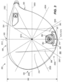
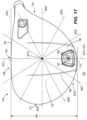
- the weight structure 580 and/or removable weight 582 can be located relative to a clock grid 2000 (illustrated in FIG. 3 ), which can be aligned with respect to the strikeface 504 when viewed from a top view.
- the clock grid comprises at least a 12 o'clock ray, a 3 o'clock ray, a 4 o'clock ray, a 5 o'clock ray, a 6 o'clock ray, a 7 o'clock ray, a 8 o'clock ray, and a 9 o'clock ray.
- the clock grid 2000 comprises a 12 o'clock ray 2012, which is aligned with the geometric center 540 of the strikeface 504.
- the 12 o'clock ray 2012 is orthogonal to the X'Y' plane.
- Clock grid 2000 can be centered along 12 o'clock ray 2012, at a midpoint between the front end 508 and back end 510 of the club head 500.
- clock grid centerpoint 2010 can be centered proximate to a geometric centerpoint of golf club head 500 when viewed from a bottom view.
- the clock grid 2000 also comprises a 3 o'clock ray 2003 extending towards the heel 520, and a 9 o'clock ray 2009 extending towards the toe 522 of the club head 500.
- a weight perimeter 584 of the weight structure 580 is located in the present embodiment towards the back end 510, at least partially bounded between a 4 o'clock ray 2004 and 8 o'clock ray 2008 of clock grid 2000, while a weight center 586 of a removable weight 582 positioned within weight structure 580 is located between a 5 o'clock ray 2005 and a 7 o'clock ray 2007.
- the weight perimeter 584 is fully bounded between the 4 o'clock ray 2004 and the 8 o'clock ray 2008.
- the weight perimeter 584 is defined external to the club head 500 in the present example, there can be other examples where the weight perimeter 584 may extend into an interior of, or be defined within, the club head 500.
- the location of the weight structure 580 can be established with respect to a broader area.
- the weight perimeter 584 of the weight structure 580 can be located towards the back end 510, at least partially bounded between the 4 o'clock ray 2004 and 9 o'clock ray 2009 of the clock grid 2000, while the weight center 586 can be located between the 5 o'clock ray 2005 and 8 o'clock ray 2008.
- the weight structure 580 protrudes from the external contour of the sole 518, and is thus at least partially external to allow for greater adjustment of the head CG 570.
- the weight structure 580 can comprise a mass of approximately 2 grams to approximately 50 grams, and/or a volume of approximately 1 cc to approximately 30 cc. In other examples, the weight structure 580 can remain flush with the external contour of the body 502.
- the removable weight 582 can comprise a mass of approximately 0.5 grams to approximately 30 grams, and can be replaced with one or more other similar removable weights to adjust the location of the head CG 570.
- the weight center 586 can comprise at least one of a center of gravity of the removable weight 582, and/or a geometric center of removable weight 582.
- the club head 500 can include one or more embedded weights to position the discretionary weight on the sole 518, in the skirt 528, and/or near the back end 510 of the club head 500 to achieve a low and back head CG position.
- the one or more embedded weights of club head 500 can be similar or identical to the one or more embedded weights 383 of club head 300.
- the one or more embedded weights are permanently fixed to or within the club head 500.
- the embedded weight can be similar to the high density metal piece (HDMP) described in U.S. Provisional Patent Appl. No. 62/372,870 , entitled "Embedded High Density Casting.”
- HDMP high density metal piece
- the one or more embedded weights are positioned near the back end 510 of the club head 500.
- a weight center of the embedded weight can be located between the 5 o'clock ray 2005 and 7 o'clock ray 2007, or between the 5 o'clock ray 2005 and 8 o'clock ray 2008 of the clock grid 2000.
- the one or more embedded weights can be positioned on the skirt and near the back end of the club head, on the sole and near the back end of the club head, or on the skirt and the sole near the back end of the club head.
- the weight center of the one or more embedded weights is positioned within 2.5 mm (0.10 inches), within 5.1 mm (0.20 inches), within 7.6 mm (0.30 inches), within 10.2 mm (0.40 inches), within 12.7 mm (0.50 inches).
- the weight center of the one or more embedded weights is positioned within 15.2 mm (0.60 inches), within 17.8 mm (0.70 inches), within 20.3 mm (0.80 inches), within 22.9 mm (0.90 inches), within 25.4 mm (1.0 inches), within 27.9 mm (1.1 inches), within 30.5 mm (1.2 inches), within 33.0 mm (1.3 inches), within 35.6 mm (1.4 inches), or within 38.1 mm (1.5 inches) of a perimeter of the club head 500 when viewed from a top view.
- the proximity of the embedded weight to the perimeter of the club head 500 can maximize the low and back head CG position, the crown-to-sole moment of inertia I xx , and/or the heel-to-toe moment of inertia I yy .
- the weight center of the one or more embedded weights is positioned at a distance from the head CG 570 greater than 41 mm (1.6 inches), greater than 43 mm (1.7 inches), greater than 46 mm (1.8 inches), greater than 48 mm (1.9 inches), greater than 51 mm (2.0 inches), greater than 53 mm (2.1 inches).
- the weight center 387 of the one or more embedded weights is positioned at a distance from the head CG 570 greater than 56 mm (2.2 inches), greater than 58 mm (2.3 inches), greater than 61 mm (2.4 inches), greater than 64 mm (2.5 inches), greater than 66 mm (2.6 inches), greater than 69 mm (2.7 inches), greater than 71 mm (2.8 inches), greater than 74 mm (2.9 inches), or greater than 76 mm (3.0 inches).
- the weight center of the one or more embedded weights is positioned at a distance from the geometric center 540 of the strikeface 504 greater than 102 mm (4.0 inches), greater than 104 mm (4.1 inches), greater than 107 mm (4.2 inches), greater than 109 mm (4.3 inches), greater than 112 mm (4.4 inches), greater than 114 mm (4.5 inches), greater than 117 mm (4.6 inches), greater than 119 mm (4.7 inches), greater than 122 mm (4.8 inches), greater than 124 mm (4.9 inches), or greater than 127 mm (5.0 inches).
- the one or more embedded weights can comprise a mass between 3.0 - 70 grams.
- the one or more embedded weights can comprise a mass between 3.0 - 25 grams, between 30 - 50 grams, between 40 - 60 grams, or between 50-70 grams.
- the one or more embedded weights can comprise a mass between 10 - 30 grams, or between 20 - 40 grams.
- each of the embedded weights can comprise the same or a different mass.
- the one or more embedded weights can comprise a material having a specific gravity between 10.0 - 22.0.
- the one or more embedded weights can comprise a material having a specific gravity greater than 10.0, greater than 11.0, greater than 12.0, greater than 13.0, greater than 14.0, greater than 15.0, greater than 16.0, greater than 17.0, greater than 18.0, or greater than 19.0.
- each of the embedded weights can comprise the same or a different material.
- the golf club head 500 can further include a steep crown angle 588 to achieve the low and back head CG position.
- the steep crown angle 588 positions the back end of the crown 516 toward the sole or ground, thereby lowering the club head CG position.
- the crown angle 588 is measured as the acute angle between a crown axis 1090 and the front plane 1020.
- the crown axis 1090 is located in a cross-section of the club head taken along a plane positioned perpendicular to the ground plane 1030 and the front plane 1020.
- the crown axis 1090 can be further described with reference to a top transition boundary and a rear transition boundary.
- the club head 500 includes a top transition boundary extending between the front end 508 and the crown 516 from near the heel 520 to near the toe 522.
- the top transition boundary includes a crown transition profile 590 when viewed from a side cross sectional view taken along a plane perpendicular to the front plane 1020 and perpendicular to the ground plane 1030 when the club head 500 is at an address position.
- the side cross sectional view can be taken along any point of the club head 500 from near the heel 520 to near the toe 522.
- the crown transition profile 590 defines a front radius of curvature 592 extending from the front end 508 of the club head 500 where the contour departs from the roll radius and/or the bulge radius of the strikeface 504 to a crown transition point 594 indicating a change in curvature from the front radius of curvature 592 to the curvature of the crown 516.
- the front radius of curvature 592 comprises a single radius of curvature extending from the top end 593 of the strikeface perimeter 542 near the crown 516 where the contour departs from the roll radius and/or the bulge radius of the strikeface 504 to a crown transition point 594 indicating a change in curvature from the front radius of curvature 592 to one or more different curvatures of the crown 516.
- the club head 500 further includes a rear transition boundary extending between the crown 516 and the skirt 528 from near the heel 520 to near the toe 522.
- the rear transition boundary includes a rear transition profile 596 when viewed from a side cross sectional view taken along a plane perpendicular to the front plane 1020 and perpendicular to the ground plane 1030 when the club head 500 is at an address position.
- the cross sectional view can be taken along any point of the club head 500 from near the heel 520 to near the toe 522.
- the rear transition profile 596 defines a rear radius of curvature 598 extending from the crown 516 to the skirt 528 of the club head 500.
- the rear radius of curvature 598 comprises a single radius of curvature that transitions the crown 516 to the skirt 528 of the club head 500 along the rear transition boundary.
- a first rear transition point 602 is located at the junction between the crown 516 and the rear transition boundary.
- a second rear transition point 603 is located at the junction between the rear transition boundary and the skirt 528 of the club head 500.
- the front radius of curvature 592 of the top transition boundary can remain constant, or can vary from near the heel 520 to near the toe 522 of the club head 500.
- the rear radius of curvature 598 of the rear transition boundary can remain constant, or can vary from near the heel 520 to near the toe 522 of the club head 500.
- the crown axis 1090 extends between the crown transition point 594 near the front end 508 of the club head 500 and the rear transition point 602 near the back end 510 of the club head 500.
- the crown angle 388 can remain constant, or can vary from near the heel 520 to near the toe 522 of the club head 500.
- the crown angle 588 can vary when the side cross sectional view is taken at different locations relative to the heel 520 and the toe 522.
- the crown angle 588 near the toe 522 is approximately 72.25 degrees
- the crown angle 588 near the heel 520 is approximately 64.5 degrees
- the crown angle 588 near the center of the golf club head 500 is approximately 64.2 degrees.
- the maximum crown angle 588 taken at any location from near the toe 522 to near the heel 520 is less than 79 degrees, less than approximately 78 degrees, less than approximately 77 degrees, less than approximately 76 degrees, less than approximately 75 degrees, less than approximately 74 degrees, less than approximately 73 degrees, less than approximately 72 degrees, less than approximately 71 degrees, less than approximately 70 degrees, less than approximately 69 degrees, or less than approximately 68 degrees.
- the maximum crown angle is between 50 degrees and 79 degrees, between 60 degrees and 79 degrees, or between 70 degrees and 79 degrees.
- the crown angle 588 near the toe 522 of the club head 500 can be less than approximately 79 degrees, less than approximately 78 degrees, less than approximately 77 degrees, less than approximately 76 degrees, less than approximately 75 degrees, less than approximately 74 degrees, less than approximately 73 degrees, less than approximately 72 degrees, less than approximately 71 degrees, less than approximately 70 degrees, less than approximately 69 degrees, or less than approximately 68 degrees.
- the crown angle 588 taken along a side cross sectional view positioned approximately 25 mm (1.0 inch) toward the toe 522 from the geometric center 540 of the strikeface 504 can be less than 79 degrees, less than 78 degrees, less than 77 degrees, less than 76 degrees, less than 75 degrees, less than 74 degrees, less than 73 degrees, less than 72 degrees, less than 71 degrees, less than 70 degrees, less than 69 degrees, or less than 68 degrees.
- the crown angle 588 near the heel 522 can be less than approximately 70 degrees, less than approximately 69 degrees, less than approximately 68 degrees, less than approximately 67 degrees, less than approximately 66 degrees, less than approximately 65 degrees, less than approximately 64 degrees, less than approximately 63 degrees, less than approximately 62 degrees, less than approximately 61 degrees, less than approximately 60 degrees, less than approximately 59 degrees.
- the crown angle 588 taken along a side cross sectional view positioned approximately 25 mm (1.0 inch) toward the heel 522 from the geometric center 540 of the strikeface 504 can be less than approximately 70 degrees, less than approximately 69 degrees, less than approximately 68 degrees, less than approximately 67 degrees, less than approximately 66 degrees, less than approximately 65 degrees, less than approximately 64 degrees, less than approximately 63 degrees, less than approximately 62 degrees, less than approximately 61 degrees, less than approximately 60 degrees, less than approximately 59 degrees.
- the crown angle 588 near the center of the club head 500 can be less than 75 degrees, less than 74 degrees, less than 73 degrees, less than 72 degrees, less than 71 degrees, less than approximately 70 degrees, less than approximately 69 degrees, less than approximately 68 degrees, less than approximately 67 degrees, less than approximately 66 degrees, less than approximately 65 degrees, less than approximately 64 degrees, less than approximately 63 degrees, less than approximately 62 degrees, less than approximately 61 degrees, less than approximately 60 degrees, less than approximately 59 degrees.
- the crown angle 588 taken along a side cross sectional view positioned approximately at the geometric center 540 of the strikeface 504 can be less than approximately 70 degrees, less than approximately 69 degrees, less than approximately 68 degrees, less than approximately 67 degrees, less than approximately 66 degrees, less than approximately 65 degrees, less than approximately 64 degrees, less than approximately 63 degrees, less than approximately 62 degrees, less than approximately 61 degrees, less than approximately 60 degrees, less than approximately 59 degrees.
- reducing the crown angle 588 compared to current club heads generates a steeper crown or a crown positioned closer to the ground plane 1030 when the club head 500 is at an address position. Accordingly, the reduced crown angle 588 can result in a lower head CG position compared to a club head with a higher crown angle.
- the head CG height 174 and/or head CG depth 172 can be achieved by reducing the mass of the hosel sleeve 534. Removing excess weight from the hosel sleeve 534 results in increased discretionary weight that can be strategically repositioned to regions of the club head 500 to achieve the desired low and back club head CG position.
- Reducing the mass of the hosel sleeve 534 can be achieved by thinning the sleeve walls, reducing the height of the hosel sleeve 534, reducing the diameter of the hosel sleeve 534, and/or by introducing voids in the walls of the hosel sleeve 534.
- the mass of the hosel sleeve 534 can be less than 6 grams, less than 5.5 grams, less than 5.0 grams, less than 4.5 grams, or less than 4.0 grams.
- the club head 500 having the reduced mass hosel sleeve 534 can result in a lower (close to the sole) and farther back (closer to the back end) club head CG position than a similar club head 500 with a heavier hosel sleeve.
- the club head 500 comprises a low and back club head CG position and an increased club head moment of inertia, in combination with reduced aerodynamic drag.
- the club head 500 experiences an aerodynamic drag force less than approximately 5.8 N (1.3 lbf), less than 5.56 N (1.25 lbf), less than 5.3 N (1.2 lbf), less than 5.12 N (1.15 lbf), less than 4.9 N (1.1 lbf), less than 4.67 N (1.05 lbf), or less than 4.4 N (1.0 lbf) when tested in a wind tunnel with a squared face and an air speed of 164 km/h (102 miles per hour (mph)).
- the club head 500 experiences an aerodynamic drag force less than approximately 5.8 N (1.3 lbf), less than 5.56 N (1.25 lbf), less than 5.3 N (1.2 lbf), less than 5.12 N (1.15 lbf), less than 4.9 N (1.1 lbf), less than 4.67 N (1.05 lbf), or less than 4.4 N (1.0 lbf) when simulated using computational fluid dynamics with a squared face and an air speed of 164 km/h (102 miles per hour (mph)).
- the airflow experienced by the club head 500 having the squared face is directed at the strikeface 504 in a direction perpendicular to the X'Y' plane.
- the club head 500 having reduced aerodynamic drag can be achieved using various means, as described below.
- reducing the crown angle 588 to form a steeper crown and lower head CG position may result in an undesired increase in aerodynamic drag due to increased air flow separation over the crown during a swing.
- a maximum crown height 604 can be increased.
- the maximum crown height 604 is the greatest distance between the surface of the crown 516 and the crown axis 1090 taken at any side cross sectional view of the club head 500 along a plane positioned parallel to the Y'Z' plane.
- a greater maximum crown height 604 results in the crown having a greater curvature. A greater curvature in the crown 516 moves the location of the air flow separation during a swing further back on the club head 500.
- a greater curvature allows the airflow to stay attached to club head 500 for a longer distance along the crown 516 during a swing. Moving the airflow separation point back on the crown 516 can result in reduced aerodynamic drag and increased club head swing speeds, thereby resulting in increased ball speed and distance.
- the maximum crown height 404 can be greater than approximately 0.20 inch (5mm), greater than approximately 0.30 inch (7.5mm), greater than approximately 0.40 inch (10mm), greater than approximately 0.50 inch (12.5mm), greater than approximately 0.60 inch (15mm), greater than approximately 0.70 inch (17.5mm), greater than approximately 0.80 inch (20mm), greater than approximately 0.90 inch (22.5mm), or greater than approximately 1.0 inch (25mm). Further, in other embodiments, the maximum crown height can be within the range of 0.20 inch (5mm) to 0.60 inch (15mm), or 0.40 inch (10mm) to 0.80 inch (20mm), or 0.60 inch (15mm) to 1.0 inch (25mm). For example, in some embodiments, the maximum crown height 404 can be approximately 0.52 inch (13.3mm), approximately 0.54 inch (13.8mm), approximately 0.59 inch (15mm), approximately 0.65 inch (16.5mm), or approximately 0.79 inch (20mm).
- the transition profiles of the club head 500 from the strikeface 504 to the crown 516, the strikeface 504 to the sole 518, and/or the crown 516 to the sole 518 along the back end 510 of the club head 500 can affect the aerodynamic drag on the club head 500 during a swing.
- the club head 500 having the top transition boundary defining the crown transition profile 590, and the rear transition boundary defining the rear transition profile 596 further includes a sole transition boundary defining a sole transition profile 610.
- the sole transition boundary extends between the front end 508 and the sole 518 from near the heel 520 to near the toe 522.
- the sole transition boundary includes a sole transition profile 610 when viewed from a side cross sectional view taken along a plane parallel to the Y'Z' plane. The side cross sectional view can be taken along any point of the club head 500 from near the heel 520 to near the toe 522.
- the sole transition profile 610 defines a sole radius of curvature 612 extending from the front end 508 of the club head 500 where the contour departs from the roll radius and/or the bulge radius of the strikeface 504 to a sole transition point 614 indicating a change in curvature from sole radius of curvature 612 to the curvature of the sole 518.
- the sole radius of curvature 612 comprises a single radius of curvature extending from the bottom end 613 of the strikeface perimeter 542 near the sole 518 where the contour departs from the roll radius and/or the bulge radius of the strikeface 504 to a sole transition point 614 indicating a change in curvature from the sole radius of curvature 612 to a curvature of the sole 614.
- the crown transition profile 590, the sole transition profile 610, and the rear transition profile 596 can be similar to the crown transition, sole transition, and rear transition profiles described in U.S. Patent No. 15/233,486 , entitled “Golf Club Head with Transition Profiles to Reduce Aerodynamic Drag.”
- the front radius of curvature 592 can be similar to the first crown radius of curvature
- the sole radius of curvature 612 can be similar to the first sole radius of curvature
- the rear radius of curvature 398 can be similar to the rear radius of curvature described U.S. Patent No. 15/233,486 , entitled “Golf Club Head with Transition Profiles to Reduce Aerodynamic Drag.”
- front radius of curvature 592 can range from approximately 0.18 to 0.30 inches (0.46 to 0.76 cm). Further, in some examples useful for understanding the invention, the front radius of curvature 592 can be less than 0.40 inches (1.02 cm), less than 0.375 inches (0.95 cm), less than 0.35 inches (0.89 cm), less than 0.325 inches (0.83 cm), and in some embodiments the front radius of curvature 592 can be less than 0.30 inches 0.76 cm). For example, the front radius of curvature 592 may be approximately 0.18 inches (0.46 cm), 0.20 inches (0.51 cm), 0.22 inches (0.66 cm), 0.24 inches (0.61 cm), 0.26 inches (0.66 cm), 0.28 inches (0.71 cm), or 0.30 inches (0.76 cm).
- the sole radius of curvature 612 can range from approximately 0.25 to 0.50 inches (0.76 to 1.27 cm).
- the sole radius of curvature 612 can be less than approximately 0.5 inches (1.27 cm), less than approximately 0.475 inches (1.21 cm), less than approximately 0.45 inches (1.14 cm), less than approximately 0.425 inches (1.08 cm), or less than approximately 0.40 inches (1.02 cm).
- the sole radius of curvature 612 can be approximately 0.30 inches (0.76 cm), 0.35 inches (0.89 cm), 0.40 inches (1.02 cm), 0.45 inches (1.14 cm), or 0.50 inches (1.27 cm).
- the rear radius of curvature 598 can range from approximately 0.10 to 0.25 inches (0.25 to 0.64 cm).
- the rear radius of curvature 598 can be less than approximately 0.3 inches (0.76 cm), less than approximately 0.275 inches (0.70 cm), less than approximately 0.25 inches (0.64 cm), less than approximately 0.225 inches (0.57 cm), or less than approximately 0.20 inches (0.51 cm).
- the rear radius of curvature 598 can be approximately 0.10 inches (0.25 cm), 0.15 inches (0.38 cm), 0.20 inches (0.51 cm), or 0.25 inches (0.64 cm).
- the club head 500 can further include a plurality of turbulators 614, as described in U.S. Patent Appl. No. 13/536,753 , now U.S. Patent No. 8,608,587, granted on December 17, 2013 , entitled "Golf Club Heads with Turbulators and Methods to Manufacture Golf Club Heads with Turbulators,".
- the plurality of turbulators 614 disrupt the airflow thereby creating small vortices or turbulence inside the boundary layer to energize the boundary layer and delay separation of the airflow on the crown during a swing.
- the plurality of turbulators 614 can be adjacent to the crown transition point 794 of the club head 500.
- the plurality of turbulators 614 project from an outer surface of the crown 508 and include a length extending between the front end 508 and the back end 510 of the club head 500, and a width extending from the heel 520 to the toe 522 of the club head 500.
- the length of the plurality of turbulators is greater than the width.
- the plurality of turbulators 614 can comprise the same width.
- the plurality of turbulators 614 can vary in height profile.
- the plurality of turbulators 614 can be higher toward the apex of the crown 516 than in comparison to the front of the crown 516. In other embodiments, the plurality of turbulators 614 can be higher toward the front of the crown 516, and lower in height toward the apex of the crown 516. In other embodiments, the plurality of turbulators 614 can comprise a constant height profile. Further, in many embodiments, at least a portion of at least one turbulator is located between the strikeface 504 and an apex of the crown 516, and the spacing between adjacent turbulators is greater than the width of each of the adjacent turbulators.
- the club head 500 can further include a cavity 620 located at the back end 510 and in the trailing edge 528 of the club head 500.
- the cavity can be similar to cavity 420 on club head 300. Further, the cavity can be similar to the cavity described in U.S. Patent Appl. No. 14/882,092 , entitled "Golf Club Heads with Aerodynamic Features and Related Methods.”
- the cavity 620 can break the vortices generated behind golf club head 500 into smaller vortices to reduce the size of the wake and/or reduce drag. In some embodiments, breaking the vortices into smaller vortices can generate a region of high pressure behind golf club head 500.
- this region of high pressure can push golf club head 500 forward, reduce drag, and/or enhance the aerodynamic design of golf club head 500.
- the net effect of smaller vortices and reduced drag is an increase in the speed of golf club head 500. This effect can lead to higher speeds at which a golf ball leaves strikeface after impact to increase ball travel distance.
- the cavity 620 can include a back wall 622, similar to back wall 422, that is oriented in a direction perpendicular to the X'Z' plane and can include a width measured in a direction from the heel 520 to the toe 522, a depth 624 (similar to depth 424 of cavity 420), and a height 626 (similar to height 426 of cavity 420).
- the width of the cavity 620 can be approximately 1.0 inches (approximately 2.54 centimeters (cm)) to approximately 8 inch (approximately 20.32 cm), approximately 1.0 inches (approximately 2.54 cm) to approximately 2.25 inches (approximately 5.72 cm), or approximately 1.75 inches (approximately 4.5 cm) to approximately 2.25 inches (approximately 5.72 cm).
- the width of the cavity 620 can be approximately 2.0 inches (5.08 cm), 3.0 inches (7.62 cm), 4.0 inches (10.16 cm), 5.0 inches (12.7 cm), 6.0 inches (15.24 cm), or 7.0 inches (17.78 cm).
- the width of the cavity 620 can remain constant from near the top of the cavity (toward the crown 516 of the club head 500) to near the bottom of the cavity (toward the sole 518 of the club head 500). In other embodiments, the width of the cavity can vary from near the top to near the bottom. In some embodiments, the width of the cavity can be largest near the top and smallest near the bottom. In other embodiments, the width of the cavity can vary according to any profile. For example, in other embodiments, the width of the cavity can be longest at the top, at the bottom, at the center, or at any other location extending from the top to the bottom of the cavity 620.
- the depth 624 of the cavity 620 can be approximately 0.025 inch (approximately 0.127 cm) to approximately 0.250 inch (approximately 0.635 cm), or approximately 0.025 inch (approximately 0.127 cm) to approximately 0.150 inch (approximately 0.381 cm).
- the depth 624 of the cavity 620 can be approximately 0.1 inch (approximately 0.254 cm), or approximately 0.05 inch (approximately 0.127 cm).
- the depth of the cavity can remain constant between the heel and the toe and/or between the top and the bottom of the cavity.
- the depth of the cavity can vary between the heel and the toe and/or between the top and the bottom of the cavity.
- the depth of the cavity can be the largest near the heel, near the toe, near the crown, near the sole, near the center, or at any combination of the described locations.
- the height 626 of the cavity 620 can be measured in a direction from the crown 516 to the sole 518.
- the height 626 of the cavity 620 can be approximately 0.19 inch (approximately 0.48 cm) to approximately 0.21 inch (approximately 0.53 cm).
- the height 626 of the cavity 620 can be approximately 0.10 inch (approximately 0.25 cm) to approximately 0.50 inch (approximately 1.27 cm).
- the height 626 of the cavity 620 can be approximately 0.10 inch (approximately 0.25 cm) to approximately 0.40 inch (approximately 1.02 cm).
- the height 626 of the cavity 620 can be approximately 0.10 inch (approximately 0.25 cm) to approximately 0.30 inch (approximately 0.76 cm). In some embodiments, the height 626 of the cavity 620 can be approximately 0.10 inch (approximately 0.25 cm) to approximately 0.20 inch (approximately 0.51 cm). In some embodiments, the height of the cavity can remain constant between the heel and the toe of the cavity. In other embodiments, the height of the cavity can vary between the heel and the toe of the cavity. For example, the height of the cavity can be the largest near the heel, near the toe, near the center, or at any combination of the described locations.
- the hosel structure 530 can have a smaller outer diameter to reduce the aerodynamic drag on the club head 500 during a swing, compared to a similar club head having a larger diameter hosel structure. In many embodiments, the hosel structure 530 has an outer diameter less than 13.84 mm (0.545 inches).
- the hosel structure 530 can have an outer diameter less than 15.2 mm (0.60 inches), less than 15.0 mm (0.59 inches), less than 14.7 mm (0.58 inches), less than 14.5 mm (0.57 inches), less than 14.2 mm (0.56 inches), less than 14.0 mm (0.55 inches), less than 13.7 mm (0.54 inches), less than 13.5 mm (0.53 inches), less than 13.2 mm (0.52 inches), less than 13.0 mm (0.51 inches), or less than 12.7 mm (0.50 inches).
- the outer diameter of the hosel structure 530 is reduced while maintaining adjustability of the loft angle and/or lie angle of the club head 500.
- the club head 500 further comprises a front projected area and a side projected area.
- the front projected area is the area of the club head 500 visible from the front view, as illustrated in FIG. 1 , and projected on the X'Y' plane.
- the side projected area is the area of the club head 500 visible from the side view and projected on the Y'Z' plane.
- the front projected area of the club head 500 can be between 0.00400 m 2 and 0.00700 m 2 .
- the front projected area of the club head is 0.00655 m 2 .
- the front projected area can be between 0.00400 m 2 and 0.00665 m 2 , between 0.00400 m 2 and 0.00675 m 2 , between 0.00400 m 2 and 0.00685 m 2 , or between 0.00400 m 2 and 0.00695 m 2 .
- the side projected area of the club head 500 can be between 0.00500 m 2 and 0.00650 m 2 .
- the front projected area of the club head is 0.00579 m 2 .
- the front projected area can be between 0.00545 m 2 and 0.00565 m 2 , between 0.00535 m 2 and 0.00575 m 2 , between 0.00525 m 2 and 0.00585 m 2 , or between 0.00515 m 2 and 0.00595 m 2 .
- the club head 500 described herein increases or maximizes the club head moment of inertia, while simultaneously maintaining or reducing aerodynamic drag. Accordingly, the club head 500 having improved impact performance characteristics (e.g. spin, launch angle, ball speed, and forgiveness) also balances or improves swing performance characteristics (e.g. aerodynamic drag, ability to square the club head at impact, and swing speed).
- impact performance characteristics e.g. spin, launch angle, ball speed, and forgiveness
- swing performance characteristics e.g. aerodynamic drag, ability to square the club head at impact, and swing speed.
- the aerodynamic drag of the club head is measured using computational fluid dynamic simulations with the front end of the club head oriented square into the airstream at an air speed of 164 km/h (102 miles per hour (mph)). In other embodiments, the aerodynamic drag can be measured using other methods, such as using wind tunnel testing.
- FIGs. 10A-C illustrate that for many known club heads having volume and/or loft angle similar to club head 300 or club head 500, as the club head moment of inertia increases (to increase club head forgiveness), the force of drag during a swing increases (thereby reducing swing speed and ball distance).
- the club head 300, 500 described herein increases or maximizes the club head moment of inertia compared to known club heads having similar volume and/or loft angle, while simultaneously maintaining or reducing aerodynamic drag. Accordingly, the club head 300, 500 having improved impact performance characteristics (e.g. spin, launch angle, ball speed, and forgiveness) also balances or improves swing performance characteristics (e.g. aerodynamic drag, ability to square the club head at impact, and swing speed).
- impact performance characteristics e.g. spin, launch angle, ball speed, and forgiveness
- swing performance characteristics e.g. aerodynamic drag, ability to square the club head at impact, and swing speed.
- the club head 300, 500 satisfies one or more of the following relations, such that the combined moment of inertia (I xx +I yy ) of the club head is increased, while maintaining or reducing the drag force (F D ) on the club head, compared to known golf club heads having similar volume and/or loft angle.
- the club head 300, 500 satisfies Relation 3, and has a combined moment of inertia greater than 9000 g ⁇ cm 2 .
- the club head 300, 500 can satisfy Relation 3, and can have a combined moment of inertia greater than 9010 g ⁇ cm 2 , greater than 9025 g ⁇ cm 2 , greater than 9050 g ⁇ cm 2 , greater than 9075 g ⁇ cm 2 , greater than 10000 g ⁇ cm 2 , greater than 10250g ⁇ cm 2 , greater than 10500 g ⁇ cm 2 , greater than 10750 g ⁇ cm 2 , or greater than 11000 g ⁇ cm 2 .
- the club head 300, 500 satisfies Relation 3, and has a drag force less than 5.16 N (1.16 lbf).
- the club head 300, 500 can satisfy Relation 3, and can have a drag force less than 5.12 N (1.15 lbf), less than 4.89 N (1.10 lbf), less than 4.45 N (1.00 lbf), less than 4.003 N (0.900 lbf), less than 3.559 N (0.800 lbf), less than 3.34 N (0.75 lbf), less than 3.114 N (0.700 lbf), less than 2.669 N (0.600 lbf), or less than 2.224 N (0.500 lbf).
- the club head 300, 500 satisfies Relation 4, and has a combined moment of inertia greater than 9000 g ⁇ cm 2 .
- the club head 300, 500 can satisfy Relation 4, and can have a combined moment of inertia greater than 9010 g ⁇ cm 2 , greater than 9025 g ⁇ cm 2 , greater than 9050 g ⁇ cm 2 , greater than 9075 g ⁇ cm 2 , greater than 10000 g ⁇ cm 2 , greater than 10250g ⁇ cm 2 , greater than 10500 g ⁇ cm 2 , greater than 10750 g ⁇ cm 2 , or greater than 11000 g ⁇ cm 2 .
- the club head 300, 500 satisfies Relation 4, and has a drag force less than 5.16 N (1.16 lbf).
- the club head 300, 500 can satisfy Relation 4, and can have a drag force less than 5.12 N (1.15 lbf), less than 4.89 N (1.10 lbf), less than 4.45 N (1.00 lbf), less than 4.003 N (0.900 lbf), less than 3.559 N (0.800 lbf), less than 3.34 N (0.75 lbf), less than 3.114 N (0.700 lbf), less than 2.669 N (0.600 lbf), or less than 2.224 N (0.500 lbf).
- the club head 300, 500 satisfies Relation 5, and has a combined moment of inertia greater than 9000 g ⁇ cm 2 .
- the club head 300, 500 can satisfy Relation 5, and can have a combined moment of inertia greater than 9010g ⁇ cm 2 , greater than 9025 g ⁇ cm 2 , greater than 9050 g ⁇ cm 2 , greater than 9075 g ⁇ cm 2 , greater than 10000 g ⁇ cm 2 , greater than 10250g ⁇ cm 2 , greater than 10500 g ⁇ cm 2 , greater than 10750 g ⁇ cm 2 , or greater than 11000 g ⁇ cm 2 .
- the club head 300, 500 satisfies Relation 5, and has a drag force less than 5.16 N (1.16 lbf).
- the club head 300, 500 can satisfy Relation 5, and can have a drag force less than 5.12 N (1.15 lbf), less than 4.89 N (1.10 lbf), less than 4.45 N (1.00 lbf), less than 4.003 N (0.900 lbf), less than 3.559 N (0.800 lbf), less than 3.34 N (0.75 lbf), less than 3.114 N (0.700 lbf), less than 2.669 N (0.600 lbf), or less than 2.224 N (0.500 lbf).
- FIG. 12 illustrates that for many known club heads having a volume and/or loft angle similar to club head 300 or club head 500, as the club head CG depth increases (to increase club head forgiveness and or launch angle), the force of drag during a swing increases (thereby reducing swing speed and ball distance). For example, referring to FIG. 12 , for many known club heads, as the head CG depth increases, the force of drag on the club head increases.
- the club head 300, 500 described herein increases or maximizes the club head CG depth compared to known club heads having similar volume and/or loft angle, while simultaneously maintaining or reducing aerodynamic drag. Accordingly, the club head 300, 500 having improved impact performance characteristics (e.g. spin, launch angle, ball speed, and forgiveness) also balances or improves swing performance characteristics (e.g. aerodynamic drag, ability to square the club head at impact, and swing speed).
- impact performance characteristics e.g. spin, launch angle, ball speed, and forgiveness
- swing performance characteristics e.g. aerodynamic drag, ability to square the club head at impact, and swing speed.
- the club head 300, 500 satisfies one or more of the following relations, such that the head CG depth (CG D ) is increased, while maintaining or reducing the drag force (F D ) on the club head, compared to known golf club heads.
- the club head 300, 500 satisfies Relation 6, and has a head CG depth greater than 41.9 mm (1.65 inches).
- the club head 300, 500 can satisfy Relation 6, and can have a head CG depth greater than 40.6 mm (1.60 inches), greater than 41.1 mm (1.62 inches), greater than 41.7 mm (1.64 inches), greater than 42.7 mm (1.68 inches), greater than 43.2 mm (1.70 inches), greater than 43.7 mm (1.72 inches), greater than 44.2 mm (1.74 inches), greater than 44.7 mm (1.76 inches), greater than 45.2 mm (1.78 inches), greater than 45.7 mm (1.80 inches), greater than 47.0 mm (1.85 inches), or greater than 48.3 mm (1.90 inches).
- the club head 300, 500 satisfies Relation 6, and has a drag force less than 5.16 N (1.16 lbf).
- the club head 300, 500 can satisfy Relation 6, and can have a drag force less than 5.12 N (1.15 lbf), less than 4.89 N (1.10 lbf), less than 4.45 N (1.00 lbf), less than 4.003 N (0.900 lbf), less than 3.559 N (0.800 lbf), less than 3.34 N (0.75 lbf), less than 3.114 N (0.700 lbf), less than 2.669 N (0.600 lbf), or less than 2.224 N (0.500 lbf).
- the club head 300, 500 satisfies Relation 7, and has a combined moment of inertia greater than 9000 g ⁇ cm 2 .
- the club head 300, 500 can satisfy Relation 7, and can have a head CG depth greater than 40.6 mm (1.60 inches), greater than 41.1 mm (1.62 inches), greater than 41.7 mm (1.64 inches), greater than 42.7 mm (1.68 inches), greater than 43.2 mm (1.70 inches), greater than 43.7 mm (1.72 inches), greater than 44.2 mm (1.74 inches), greater than 44.7 mm (1.76 inches), greater than 45.2 mm (1.78 inches), greater than 45.7 mm (1.80 inches), greater than 47.0 mm (1.85 inches), or greater than 48.3 mm (1.90 inches).
- the club head 300, 500 satisfies Relation 7, and has a drag force less than 5.16 N (1.16 lbf).
- the club head 300, 500 can satisfy Relation 7, and can have a drag force less than 5.12 N (1.15 lbf), less than 4.89 N (1.10 lbf), less than 4.45 N (1.00 lbf), less than 4.003 N (0.900 lbf), less than 3.559 N (0.800 lbf), less than 3.34 N (0.75 lbf), less than 3.114 N (0.700 lbf), less than 2.669 N (0.600 lbf), or less than 2.224 N (0.500 lbf).
- the club head 300, 500 satisfies Relation 8, and has a combined moment of inertia greater than 9000 g ⁇ cm 2 .
- the club head 300, 500 can satisfy Relation 8, and can have a head CG depth greater than 40.6 mm (1.60 inches), greater than 41.1 mm (1.62 inches), greater than 41.7 mm (1.64 inches), greater than 42.7 mm (1.68 inches), greater than 43.2 mm (1.70 inches), greater than 43.7 mm (1.72 inches), greater than 44.2 mm (1.74 inches), greater than 44.7 mm (1.76 inches), greater than 45.2 mm (1.78 inches), greater than 45.7 mm (1.80 inches), greater than 47.0 mm (1.85 inches), or greater than 48.3 mm (1.90 inches).
- the club head 300, 500 satisfies Relation 8, and has a drag force less than 5.16 N (1.16 lbf).
- the club head 300, 500 can satisfy Relation 8, and can have a drag force less than 5.12 N (1.15 lbf), less than 4.89 N (1.10 lbf), less than 4.45 N (1.00 lbf), less than 4.003 N (0.900 lbf), less than 3.559 N (0.800 lbf), less than 3.34 N (0.75 lbf), less than 3.114 N (0.700 lbf), less than 2.669 N (0.600 lbf), or less than 2.224 N (0.500 lbf).
- the combined moment of inertia and/or head CG depth many known golf club heads are limited.
- many known golf club heads having a volume and/or loft angle similar to club head 300 or club head 500 have a head CG depth less than 41 mm (1.6 inches) and a combined moment of inertia less than 8900 g ⁇ cm 2 .
- the club head 300, 500 described herein has a greater head CG depth and a greater combined moment of inertia than known club heads having similar volume and/or loft angle, while simultaneously maintaining or reducing aerodynamic drag.
- the club head 300, 500 having improved impact performance characteristics e.g. spin, launch angle, ball speed, and forgiveness
- swing performance characteristics e.g. aerodynamic drag, ability to square the club head at impact, and swing speed).
- the club head 300, 500 has a head CG depth greater than 41.9 mm (1.65 inches) and a combined moment of inertia greater than 9000 g ⁇ cm 2 .
- the club head 300, 500 can have a head CG depth greater than 40.6 mm (1.60 inches), greater than 41.1 mm (1.62 inches), greater than 41.7 mm (1.64 inches), greater than 42.7 mm (1.68 inches), greater than 43.2 mm (1.70 inches), greater than 43.7 mm (1.72 inches), greater than 44.2 mm (1.74 inches), greater than 44.7 mm (1.76 inches), greater than 45.2 mm (1.78 inches), greater than 45.7 mm (1.80 inches), greater than 47.0 mm (1.85 inches), or greater than 48.3 mm (1.90 inches).
- the club head 300, 500 can have a combined moment of inertia greater than 9010 g ⁇ cm 2 , greater than 9025 g ⁇ cm 2 , greater than 9050 g ⁇ cm 2 , greater than 9075 g ⁇ cm 2 , greater than 10000 g ⁇ cm 2 , greater than 10250g ⁇ cm 2 , greater than 10500 g ⁇ cm 2 , greater than 10750 g ⁇ cm 2 , or greater than 11000 g ⁇ cm 2 .
- a golf club head 700 can comprise a fairway wood-type club head.
- club head 700 comprises the same or similar parameters as club head 100, wherein the parameters are described with the club head 100 reference numbers plus 600.
- the loft angle of the club head 700 is less than approximately 35 degrees, less than approximately 34 degrees, less than approximately 33 degrees, less than approximately 32 degrees, less than approximately 31 degrees, or less than approximately 30 degrees. Further, in many embodiments, the loft angle of the club head 700 is greater than approximately 12 degrees, greater than approximately 13 degrees, greater than approximately 14 degrees, greater than approximately 15 degrees, greater than approximately 16 degrees, greater than approximately 17 degrees, greater than approximately 18 degrees, greater than approximately 19 degrees, or greater than approximately 20 degrees. For example, in some embodiments, the loft angle of the club head 700 can be between 12 degrees and 35 degrees, between 15 degrees and 35 degrees, between 20 degrees and 35 degrees, or between 12 degrees and 30 degrees.
- the volume of the club head 700 is less than approximately 400 cc, less than approximately 375 cc, less than approximately 350 cc, less than approximately 325 cc, less than approximately 300 cc, less than approximately 275 cc, less than approximately 250 cc, less than approximately 225 cc, or less than approximately 200 cc.
- the length 762 of the club head 700 is can be between 89 and 120.7 mm (3.5 inches and 4.75 inches), between 102 and 123.2 mm (4.0 inches and 4.85 inches), between 89 and 127 mm (3.5 inches and 5.0 inches), or between 102 and 114 mm (4.0 inches and 4.5 inches).
- the depth 760 of the club head 700 is at least 17.8 mm (0.70 inches) less than the length 762 of the club head 700.
- the depth 760 of the club head 700 can be between 69.9 and 114 mm (2.75 inches and 4.5 inches), between 76 and 102 mm (3.0 inches and 4.0 inches), between 76 and 95.3 mm (3.0 inches and 3.75 inches), or between 76 and 123.2 mm (3.0 inches and 4.85 inches).
- the height 764 of the club head 700 is less than approximately 51 mm (2.0 inches). In other embodiments, the height 764 of the club head 700 is less than 64 mm (2.5 inches), less than 61 mm (2.4 inches), less than 58 mm (2.3 inches), less than 56 mm (2.2 inches), less than 53 mm (2.1 inches), less than 48 mm (1.9 inches), or less than 46 mm (1.8 inches).
- the height 764 of the club head 700 can be between 33 - 43 mm (1.3 - 1.7 inches), between 38 - 51 mm (1.5 - 2.0 inches), between 44.5 - 64 mm (1.75 - 2.5 inches), between 44.5 - 51 mm (1.75 - 2.0 inches), or between 51 - 64 mm (2.0 - 2.5 inches).
- the face height 744 of the club head can be approximately 0.5 inches (12.7 mm) to approximately 2.0 inches (50.8 mm).
- the club head 700 can comprise a mass between 185 grams and 250 grams.
- the club head 700 further comprises a balance of various additional parameters, such as head CG position, club head moment of inertia, and aerodynamic drag, to provide both improved impact performance characteristics (e.g. spin, launch angle, speed, forgiveness) and swing performance characteristics (e.g. aerodynamic drag, ability to square the club head at impact).
- improved impact performance characteristics e.g. spin, launch angle, speed, forgiveness
- swing performance characteristics e.g. aerodynamic drag, ability to square the club head at impact.
- the balance of parameters described below provides improved impact performance while maintaining or improving swing performance characteristics.
- the balance of parameters described below provides improved swing performance characteristics while maintaining or improving impact performance characteristics.
- a low and back club head CG and increased moment of inertia can be achieved by increasing discretionary weight and repositioning discretionary weight in regions of the club head having maximized distances from the head CG.
- Increasing discretionary weight can be achieved by thinning the crown and/or using optimized materials, as described above relative to the head CG position.
- Repositioning discretionary weight to maximize the distance from the head CG can be achieved using removable weights, embedded weights, or a steep crown angle, as described above relative to the head CG position.
- the club head 700 comprises a crown-to-sole moment of inertia I xx greater than approximately 1500 g ⁇ cm 2 , greater than approximately 1600 g ⁇ cm 2 , greater than approximately 1600 g ⁇ cm 2 , greater than approximately 1650 g ⁇ cm 2 , greater than approximately 1700 g ⁇ cm 2 , greater than approximately 1750 g ⁇ cm 2 , greater than approximately 1800 g ⁇ cm 2 , greater than approximately 1850 g ⁇ cm 2 , greater than approximately 1900 g ⁇ cm 2 , greater than approximately 1950 g ⁇ cm 2 , greater than approximately 2000 g ⁇ cm 2 , greater than approximately 2100 g ⁇ cm 2 , greater than approximately 2200 g ⁇ cm 2 , greater than approximately 2300 g ⁇ cm 2 , greater than approximately 2400 g ⁇ cm 2 , greater than approximately 2500 g ⁇ cm 2 , greater than approximately 2600 g ⁇ cm 2 , greater than approximately 2700 g ⁇ cm 2 ,or
- the club head 700 comprises a heel-to-toe moment of inertia I yy greater than approximately 3000 g ⁇ cm 2 , greater than approximately 3100 g ⁇ cm 2 , greater than approximately 3200 g ⁇ cm 2 , greater than approximately 3250 g ⁇ cm 2 , greater than approximately 3300 g ⁇ cm 2 , greater than approximately 3400 g ⁇ cm 2 , greater than approximately 3500 g ⁇ cm 2 , greater than approximately 3600 g ⁇ cm 2 , greater than approximately 3750 g ⁇ cm 2 , greater than approximately 4000 g ⁇ cm 2 , greater than approximately 4250 g ⁇ cm 2 , greater than approximately 4500 g ⁇ cm 2 , greater than approximately 4750 g ⁇ cm 2 , greater than approximately 5000 g ⁇ cm 2 , greater than approximately 5250 g ⁇ cm 2 , greater than approximately 5500 g ⁇ cm 2 , greater than approximately 5750 g ⁇ cm 2 , greater than approximately 6000
- the club head 700 comprises a combined moment of inertia (i.e. the sum of the crown-to-sole moment of inertia I xx and the heel-to-toe moment of inertia I yy ) greater than 4900 g ⁇ cm 2 , greater than 4950 g ⁇ cm 2 , greater than 5000 g ⁇ cm 2 , greater than 5100 g ⁇ cm 2 , greater than 5200 g ⁇ cm 2 , greater than 5300 g ⁇ cm 2 , greater than 5400 g ⁇ cm 2 , greater than 5500 g ⁇ cm 2 , greater than 5600 g ⁇ cm 2 , greater than 5700 g ⁇ cm 2 , greater than 5800 g ⁇ cm 2 , greater than 5900 g ⁇ cm 2 , or greater than 6000 g ⁇ cm 2 .
- a combined moment of inertia i.e. the sum of the crown-to-sole moment of inertia I xx and
- the club head 700 comprises a head CG height 774 less than approximately 12.7 mm (0.50 inches), less than approximately 12.07 mm (0.475 inches), less than approximately 11.4 mm (0.45 inches), less than approximately 10.80 mm (0.425 inches), less than approximately 10.2 mm (0.40 inches), less than approximately 8.9 mm (0.35 inches), less than approximately 7.6 mm (0.30 inches), less than approximately 6.4 mm (0.25 inches), and embodiments the club head 700 comprises a head CG height 774 less than approximately 5.1 mm (0.20 inches), less than 3.8 mm (0.15 inches), or less than 2.5 mm (0.10 inches).
- the club head 700 comprises a head CG height 774 having an absolute value less than approximately 12.7 mm (0.50 inches), less than approximately 12.07 mm (0.475 inches), less than approximately 11.4 mm (0.45 inches), less than approximately 10.80 mm (0.425 inches), less than approximately 10.2 mm (0.40 inches), less than approximately 8.9 mm (0.35 inches), less than approximately 7.6 mm (0.30 inches), or less than approximately 6.4 mm (0.25 inches).
- the club head 700 comprises a head CG depth 772 greater than approximately 25 mm (1.0 inches), greater than approximately 28 mm (1.1 inches), and in embodiments the club head 700 comprises a head CG depth 772 greater than approximately 31.0 mm (1.22 inches), greater than approximately 30 mm (1.2 inches), greater than approximately 33 mm (1.3 inches), greater than approximately 36 mm (1.4 inches), greater than approximately 38 mm (1.5 inches), greater than approximately 41 mm (1.6 inches), greater than approximately 43 mm (1.7 inches), or greater than approximately 46 mm (1.8 inches).
- the club head 700 having the reduced head CG height 774 can reduce the backspin of a golf ball on impact compared to a similar club head having a higher head CG height. In many embodiments, reduced backspin can increase both ball speed and travel distance for improve club head performance. Further, the club head 700 having the increased head CG depth 772 can increase the heel-to-toe moment of inertia compared to a similar club head having a head CG depth closer to the strikeface. Increasing the heel-to-toe moment of inertia can increase club head forgiveness on impact to improve club head performance. Further still, the club head 700 having the increased head CG depth 772 can increase launch angle of a golf ball on impact by increasing the dynamic loft of the club head at delivery, compared to a similar club head having a head CG depth closer to the strikeface.
- the head CG height 774 and/or head CG depth 772 can be achieved by reducing weight of the club head in various regions, thereby increasing discretionary weight, and repositioning discretionary weight in strategic regions of the club head to shift the head CG lower and farther back.
- Various means to reduce and reposition club head weight are described below.
- the head CG height 772 and/or head CG depth 774 can be achieved by thinning various regions of the club head to remove excess weight. Removing excess weight results in increased discretionary weight that can be strategically repositioned to regions of the club head 700 to achieve the desired low and back club head CG position.
- the club head 700 can have one or more thin regions.
- the one or more thin regions can be similar or identical to the one or more thin regions 376 of club head 300, or the one or more thin regions of club head 500.
- the one or more thin regions can be positioned on the strikeface 704, the body 702, or a combination of the strikeface 704 and the body 702. Further, the one or more thin regions can be positioned on any region of the body 702, including the crown 716, the sole 718, the heel 720, the toe 722, the front end 708, the back end 710, the skirt 728, or any combination of the described positions.
- the one or more thin regions can be positioned on the crown 716.
- the one or more thin regions can be positioned on a combination of the strikeface 704 and the crown 716.
- the one or more thin regions can be positioned on a combination of the strikeface 704, the crown 716, and the sole 718.
- the entire body 702 and/or the entire strikeface 704 can comprise a thin region.
- the thickness of the strikeface 704 can vary defining a maximum strikeface thickness and a minimum strikeface thickness.
- the minimum strikeface thickness can be less than 2.5 mm (0.10 inches), less than 2.3 mm (0.09 inches), less than 2.0 mm (0.08 inches), less than 1.8 mm (0.07 inches), less than 1.5 mm (0.06 inches), less than 1.3 mm (0.05 inches), less than 1.0 mm (0.04 inches), less than 0.8 mm (0.03 inches), or less than 0.5 mm (0.02 inches).
- the maximum strikeface thickness can be less than 5.1 mm (0.20 inches), less than 4.8 mm (0.19 inches), less than 4.6 mm (0.18 inches), less than 4.3 mm (0.17 inches), less than 4.1 mm (0.16 inches), less than 3.8 mm (0.15 inches), less than 3.6 mm (0.14 inches), less than 3.3 mm (0.13 inches), less than 3.0 mm (0.12 inches), less than 2.8 mm (0.11 inches), or less than 2.5 mm (0.10 inches).
- the thin regions can comprise a thickness less than approximately 0.56 mm (0.022 inches). In other embodiments, the thin regions comprise a thickness less than 0.64 mm (0.025 inches), less than 0.51 mm (0.020 inches), less than 0.48 mm (0.019 inches), less than 0.46 mm (0.018 inches), less than 0.43 mm (0.017 inches), less than 0.41 mm (0.016 inches), less than 0.38 mm (0.015 inches), less than 0.36 mm (0.014 inches), less than 0.33 mm (0.013 inches), less than 0.30 mm (0.012 inches), or less than 0.25 mm (0.010 inches).
- the thin regions can comprise a thickness between approximately 0.25 - 0.64 mm (0.010 - 0.025 inches), between approximately 0.33 - 0.56 mm (0.013 - 0.022 inches), between approximately 0.36 - 0.51 mm (0.014 - 0.020 inches), between approximately 0.38 - 0.51 mm (0.015 - 0.020 inches), between approximately 0.41 - 0.51 mm (0.016 - 0.020 inches), between approximately 0.43 - 0.51 mm (0.017 - 0.020 inches), or between approximately 0.46 - 0.51 mm (0.018 - 0.020 inches).
- the thin regions vary in shape and position and cover approximately 25% of the surface area of club head 700. In other embodiments, the thin regions can cover approximately 20-30%, approximately 15-35%, approximately 15-25%, approximately 10-25%, approximately 15-30%, or approximately 20-50% of the surface area of club head 700. Further, in other embodiments, the thin regions can cover up to 5%, up to 10%, up to 15%, up to 20%, up to 25%, up to 30%, up to 35%, up to 40%, up to 45%, or up to 50% of the surface area of club head 700.
- the crown 716 comprises one or more thin regions, such that approximately 51% of the surface area of the crown 716 comprises thin regions. In other embodiments, the crown 716 comprises one or more thin regions, such that up to 20%, up to 25%, up to 30%, up to 35%, up to 40%, up to 45%, up to 50%, up to 55%, up to 60%, up to 65%, up to 70%, up to 75%, up to 80%, up to 85%, or up to 90% of the crown 716 comprises thin regions. For example, in some embodiments, approximately 40-60% of the crown 716 can comprise thin regions. For further example, in other embodiments, approximately 50-100%, approximately 40-90%, approximately 35-65%, approximately 30-70%, or approximately 25-75% of the crown can comprise thin regions.
- the crown 716 can comprise one or more thin regions, wherein each of the one or more thin regions become thinner in a gradient fashion.
- the one or more thin regions of the crown 716 extend in a heel-to-toe direction, and each of the one or more thin regions decrease in thickness in a direction from the strikeface 704 toward the back end 710.
- the sole 718 comprises one or more thin regions, such that approximately 64% of the surface area of the sole 718 comprises thin regions. In other embodiments, the sole 718 comprises one or more thin regions, such that up to 20%, up to 25%, up to 30%, up to 35%, up to 40%, up to 45%, up to 50%, up to 55%, up to 60%, up to 65%, up to 70%, up to 75%, up to 80%, up to 85%, or up to 90% of the sole 718 comprises thin regions. For example, in some embodiments, approximately 40-60% of the sole 718 can comprise thin regions. For further example, in other embodiments, approximately 50-100%, approximately 40-90%, approximately 35-65%, approximately 30-70%, or approximately 25-75% of the sole 718 can comprise thin regions.
- the thinned regions can comprise any shape, such as circular, triangular, square, rectangular, ovular, or any other polygon or shape with at least one curved surface. Further, one or more thinned regions can comprise the same shape as or a different shape than the remaining thinned regions.
- club head 700 having thin regions can be manufacturing using centrifugal casting.
- centrifugal casting allows the club head 700 to have thinner walls than a club head manufactured using conventional casting.
- portions of the club head 700 having thin regions can be manufactured using other suitable methods, such as stamping, forging, or machining.
- the portions of the club head 700 can be coupled using epoxy, tape, welding, mechanical fasteners, or other suitable methods.
- the strikeface 704 and/or the body 702 can comprise an optimized material having increased specific strength and/or increased specific flexibility.
- the specific flexibility is measured as a ratio of the yield strength to the elastic modulus of the optimized material. Increasing specific strength and/or specific flexibility can allow portions of the club head to be thinned, while maintaining durability.
- the first material of the strikeface 704 can be an optimized material, as described in U.S Provisional Patent Appl. No 62/399,929 , entitled "Golf Club Heads with Optimized Material Properties.”
- the first material comprising an optimized titanium alloy can have a specific strength greater than or equal to approximately 900,000 PSI/lb/in 3 (224 MPa/g/cm 3 ), greater than or equal to approximately 910,000 PSI/lb/in 3 (227 MPa/g/cm 3 ), greater than or equal to approximately 920,000 PSI/lb/in 3 (229 MPa/g/cm 3 ), greater than or equal to approximately 930,000 PSI/lb/in 3 (232 MPa/g/cm 3 ), greater than or equal to approximately 940,000 PSI/lb/in 3 (234 MPa/g/cm 3 ), greater than or equal to approximately 950,000 PSI/lb/in 3 (237 MPa/g/cm 3 ), greater than or equal to approximately
- the first material comprising an optimized titanium alloy can have a specific flexibility greater than or equal to approximately 0.0075, greater than or equal to approximately 0.0080, greater than or equal to approximately 0.0085, greater than or equal to approximately 0.0090, greater than or equal to approximately 0.0091, greater than or equal to approximately 0.0092, greater than or equal to approximately 0.0093, greater than or equal to approximately 0.0094, greater than or equal to approximately 0.0095, greater than or equal to approximately 0.0096, greater than or equal to approximately 0.0097, greater than or equal to approximately 0.0098, greater than or equal to approximately 0.0099, greater than or equal to approximately 0.0100, greater than or equal to approximately 0.0105, greater than or equal to approximately 0.0110, greater than or equal to approximately 0.0115, or greater than or equal to approximately 0.0120.
- the first material comprising an optimized steel alloy can have a specific strength greater than or equal to approximately 650,000 PSI/lb/in 3 (162 MPa/g/cm 3 ), greater than or equal to approximately 700,000 PSI/lb/in 3 (174 MPa/g/cm 3 ), greater than or equal to approximately 750,000 PSI/lb/in 3 (187 MPa/g/cm 3 ), greater than or equal to approximately 800,000 PSI/lb/in 3 (199 MPa/g/cm 3 ), greater than or equal to approximately 810,000 PSI/lb/in 3 (202 MPa/g/cm 3 ), greater than or equal to approximately 820,000 PSI/lb/in 3 (204 MPa/g/cm 3 ), greater than or equal to approximately 830,000 PSI/lb/in 3 (207 MPa/g/cm 3 ), greater than or equal to approximately 840,000 PSI/lb/in 3 (209 MPa/g/cm 3 ), greater than or equal to approximately 840,000 PSI/lb
- the first material comprising an optimized steel alloy can have a specific flexibility greater than or equal to approximately 0.0060, greater than or equal to approximately 0.0065, greater than or equal to approximately 0.0070, greater than or equal to approximately 0.0075, greater than or equal to approximately 0.0080, greater than or equal to approximately 0.0085, greater than or equal to approximately 0.0090, greater than or equal to approximately 0.0095, greater than or equal to approximately 0.0100, greater than or equal to approximately 0.0105, greater than or equal to approximately 0.0110, greater than or equal to approximately 0.0115, greater than or equal to approximately 0.0120, greater than or equal to approximately 0.0125, greater than or equal to approximately 0.0130, greater than or equal to approximately 0.0135, greater than or equal to approximately 0.0140, greater than or equal to approximately 0.0145, or greater than or equal to approximately 0.0150.
- the increased specific strength and/or increased specific flexibility of the optimized first material allow the strikeface 704, or portions thereof, to be thinned, as described above, while maintaining durability. Thinning of the strikeface 704 can reduce the weight of the strikeface 704, thereby increasing discretionary weight to be strategically positioned in other areas of the club head 700 to position the head CG low and back and/or increase the club head moment of inertia.
- the second material of the body 702 can be an optimized material, as described in U.S Provisional Patent Appl. No. 62/399,929 , entitled "Golf Club Heads with Optimized Material Properties.”
- the second material comprising an optimized titanium alloy can have a specific strength greater than or equal to approximately 730,500 PSI/lb/in 3 (182 MPa/g/cm 3 ).
- the specific strength of the optimized titanium alloy can be greater than or equal to approximately 650,000 PSI/lb/in 3 (162 MPa/g/cm 3 ), greater than or equal to approximately 700,000 PSI/lb/in 3 (174 MPa/g/cm 3 ), greater than or equal to approximately 750,000 PSI/lb/in 3 (187 MPa/g/cm 3 ), greater than or equal to approximately 800,000 PSI/lb/in 3 (199 MPa/g/cm 3 ), greater than or equal to approximately 850,000 PSI/lb/in 3 (212 MPa/g/cm 3 ), greater than or equal to approximately 900,000 PSI/lb/in 3 (224 MPa/g/cm 3 ), greater than or equal to approximately 950,000 PSI/lb/in 3 (237 MPa/g/cm 3 ), greater than or equal to approximately 1,000,000 PSI/lb/in 3 (249 MPa/g/cm 3 ), greater than or equal to approximately 1,050,000 PSI/lb/in
- the second material comprising an optimized titanium alloy can have a specific flexibility greater than or equal to approximately 0.0060, greater than or equal to approximately 0.0065, greater than or equal to approximately 0.0070, greater than or equal to approximately 0.0075, greater than or equal to approximately 0.0080, greater than or equal to approximately 0.0085, greater than or equal to approximately 0.0090, greater than or equal to approximately 0.0095, greater than or equal to approximately 0.0100, greater than or equal to approximately 0.0105, greater than or equal to approximately 0.0110, greater than or equal to approximately 0.0115, or greater than or equal to approximately 0.0120.
- the second material comprising an optimized steel can have a specific strength greater than or equal to approximately 500,000 PSI/lb/in 3 (125 MPa/g/cm 3 ), greater than or equal to approximately 510,000 PSI/lb/in 3 (127 MPa/g/cm 3 ), greater than or equal to approximately 520,000 PSI/lb/in 3 (130 MPa/g/cm 3 ), greater than or equal to approximately 530,000 PSI/lb/in 3 (132 MPa/g/cm 3 ), greater than or equal to approximately 540,000 PSI/lb/in 3 (135 MPa/g/cm 3 ), greater than or equal to approximately 550,000 PSI/lb/in 3 (137 MPa/g/cm 3 ), greater than or equal to approximately 560,000 PSI/lb/in 3 (139 MPa/g/cm 3 ), greater than or equal to approximately 570,000 PSI/lb/in 3 (142 MPa/g/cm 3 ), greater than or equal to approximately 580,000 PSI
- the second material comprising an optimized steel can have a specific flexibility greater than or equal to approximately 0.0060, greater than or equal to approximately 0.0062, greater than or equal to approximately 0.0064, greater than or equal to approximately 0.0066, greater than or equal to approximately 0.0068, greater than or equal to approximately 0.0070, greater than or equal to approximately 0.0072, greater than or equal to approximately 0.0076, greater than or equal to approximately 0.0080, greater than or equal to approximately 0.0084, greater than or equal to approximately 0.0088, greater than or equal to approximately 0.0092, greater than or equal to approximately 0.0096, greater than or equal to approximately 0.0100, greater than or equal to approximately 0.0105, greater than or equal to approximately 0.0110, greater than or equal to approximately 0.0115, greater than or equal to approximately 0.0120, greater than or equal to approximately 0.0125, greater than or equal to approximately 0.0130, greater than or equal to approximately 0.0135, greater than or equal to approximately 0.0140, greater than or equal to approximately 0.0145, or greater
- the increased specific strength and/or increased specific flexibility of the optimized second material allow the body 702, or portions thereof, to be thinned, while maintaining durability. Thinning of the body 702 can reduce club head weight, thereby increasing discretionary weight to be strategically positioned in other areas of the club head 700 to position the head CG low and back and/or increase the club head moment of inertia.
- the club head 700 can include one or more weight structures 780 comprising one or more removable weights 782.
- the one or more weight structures 780 and/or the one or more removable weights 782 can be located towards the sole 718 and towards the back end 710, thereby positioning the discretionary weight on the sole 718 and near the back end 710 of the club head 700 to achieve a low and back head CG position.
- the one or more weight structures 780 removably receive the one or more removable weights 782.
- the weight structure 780 and/or removable weight 782 can be located relative to a clock grid 2000 (illustrated in FIG. 3 ), which can be aligned with respect to the strikeface 704 when viewed from a top view.
- the clock grid comprises at least a 12 o'clock ray, a 3 o'clock ray, a 4 o'clock ray, a 5 o'clock ray, a 6 o'clock ray, a 7 o'clock ray, a 8 o'clock ray, and a 9 o'clock ray.
- the clock grid 2000 comprises a 12 o'clock ray 2012, which is aligned with the geometric center 740 of the strikeface 704.
- the 12 o'clock ray 2012 is orthogonal to the X'Y' plane.
- Clock grid 2000 can be centered along 12 o'clock ray 2012, at a midpoint between the front end 708 and back end 710 of the club head 700.
- clock grid centerpoint 2010 can be centered proximate to a geometric centerpoint of golf club head 700 when viewed from a bottom view.
- the clock grid 2000 also comprises a 3 o'clock ray 2003 extending towards the heel 720, and a 9 o'clock ray 2009 extending towards the toe 722 of the club head 700.
- a weight perimeter 784 of the weight structure 780 is located in the present embodiment towards the back end 710, at least partially bounded between a 4 o'clock ray 2004 and 8 o'clock ray 2008 of clock grid 2000, while a weight center 786 of a removable weight 782 positioned within weight structure 780 is located between a 5 o'clock ray 2005 and a 7 o'clock ray 2007.
- the weight perimeter 784 is fully bounded between the 4 o'clock ray 2004 and the 8 o'clock ray 2008.
- the weight perimeter 784 is defined external to the club head 700 in the present example, there can be other examples where the weight perimeter 784 may extend into an interior of, or be defined within, the club head 700.
- the location of the weight structure 780 can be established with respect to a broader area.
- the weight perimeter 784 of the weight structure 780 can be located towards the back end, at least partially bounded between the 4 o'clock ray 2004 and 9 o'clock ray 2009 of the clock grid 2000, while the weight center 786 can be located between the 5 o'clock ray 2005 and 8 o'clock ray 2008.
- the weight structure 780 protrudes from the external contour of the sole 718, and is thus at least partially external to allow for greater adjustment of the head CG 770.
- the weight structure 780 can comprise a mass of approximately 2 grams to approximately 50 grams, and/or a volume of approximately 1 cc to approximately 30 cc. In other examples, the weight structure 780 can remain flush with the external contour of the body 702.
- the removable weight 782 can comprise a mass of approximately 0.5 grams to approximately 30 grams, and can be replaced with one or more other similar removable weights to adjust the location of the head CG 770.
- the weight center 786 can comprise at least one of a center of gravity of the removable weight 782, and/or a geometric center of removable weight 782.
- the club head 700 can include one or more embedded weights to position the discretionary weight on the sole 718, in the skirt 728, and/or near the back end 710 of the club head 700 to achieve a low and back head CG position.
- the one or more embedded weights of club head 700 can be similar or identical to the one or more embedded weights 383 of club head 300, or the one or more embedded weights of club head 500.
- the one or more embedded weights are permanently fixed to or within the club head 700.
- the embedded weight can be similar to the high density metal piece (HDMP) described in U.S. Provisional Patent Appl. No. 62/372,870 , entitled "Embedded High Density Casting.”
- HDMP high density metal piece
- the one or more embedded weights are positioned near the back end 710 of the club head.
- a weight center of the embedded weight can be 2005 and 8 o'clock ray 2008 of the clock grid.
- the one or more embedded weights can be positioned on the skirt 728 and near the back end 710 of the club head 700, on the sole 718 and near the back end 710 of the club head 700, or on the skirt 728 and the sole 718 near the back end 710 of the club head 700.
- the weight center of the one or more embedded weights is positioned within 2.5 mm (0.10 inches), within 5.1 mm (0.20 inches), within 7.6 mm (0.30 inches), within 10.2 mm (0.40 inches), within 12.7 mm (0.50 inches), and in examples useful for understanding the invention, the weight center of the one or more embedded weights is positioned within 15.2 mm (0.60 inches), within 17.8 mm (0.70 inches), within 20.3 mm (0.80 inches), within 22.9 mm (0.90 inches), within 25 mm (1.0 inches), within 28 mm (1.1 inches), within 30 mm (1.2 inches), within 33 mm (1.3 inches), within 36 mm (1.4 inches), or within 38 mm (1.5 inches) of a perimeter of the club head 700 when viewed from a top view.
- the proximity of the embedded weight to the perimeter of the club head 700 can maximize the low and back head CG position, the crown-to-sole moment of inertia I xx , and/or the heel-to-toe moment of inertia I yy .
- the weight center of the one or more embedded weights is positioned at a distance from the head CG 770 greater than 41 mm (1.6 inches), greater than 43 mm (1.7 inches), greater than 46 mm (1.8 inches), greater than 48 mm (1.9 inches), greater than 51 mm (2.0 inches), greater than 53 mm (2.1 inches).
- the weight center of the one or more embedded weights is positioned at a distance from the head CG 770 greater than 56 mm (2.2 inches), greater than 58 mm (2.3 inches), greater than 61 mm (2.4 inches), greater than 64 mm (2.5 inches), greater than 66 mm (2.6 inches), greater than 69 mm (2.7 inches), greater than 71 mm (2.8 inches), greater than 74 mm (2.9 inches), or greater than 76 mm (3.0 inches).
- the weight center of the one or more embedded weights is positioned at a distance from the geometric center 740 of the strikeface 704 greater than 102 mm (4.0 inches), greater than 104 mm (4.1 inches), greater than 107 mm (4.2 inches), greater than 109 mm (4.3 inches), greater than 112 mm (4.4 inches), greater than 114 mm (4.5 inches), greater than 117 mm (4.6 inches), greater than 119 mm (4.7 inches), greater than 122 mm (4.8 inches), greater than 124 mm (4.9 inches), or greater than 127 mm (5.0 inches).
- the one or more embedded weights can comprise a mass between 3.0 - 90 grams.
- the one or more embedded weights can comprise a mass between 3.0 - 25 grams, between 20 - 50 grams, between 30 - 60 grams, between 40 - 70 grams, between 50-80 grams, or between 60 - 90 grams.
- the one or more embedded weights can comprise a mass between 10 - 40 grams.
- each of the embedded weights can comprise the same or a different mass.
- the one or more embedded weights can comprise a material having a specific gravity between 10.0 - 22.0.
- the one or more embedded weights can comprise a material having a specific gravity greater than 10.0, greater than 11.0, greater than 12.0, greater than 13.0, greater than 14.0, greater than 15.0, greater than 16.0, greater than 17.0, greater than 18.0, or greater than 19.0.
- each of the embedded weights can comprise the same or a different material.
- the golf club head 700 can further include a steep crown angle 788 to achieve the low and back head CG position.
- the steep crown angle 788 positions the back end of the crown 716 toward the sole 718 or ground, thereby lowering the club head CG position.
- the crown angle 788 is measured as the acute angle between a crown axis 1090 and the front plane 1020.
- the crown axis 1090 is located in a cross-section of the club head 700 taken along a plane positioned perpendicular to the ground plane 1030 and the front plane 1020.
- the crown axis 1090 can be further described with reference to a top transition boundary and a rear transition boundary.
- the club head 700 includes a top transition boundary extending between the front end 708 and the crown 716 from near the heel 720 to near the toe 722.
- the top transition boundary includes a crown transition profile 790 when viewed from a side cross sectional view taken along a plane perpendicular to the front plane 1020 and perpendicular to the ground plane 1030 when the club head 700 is at an address position.
- the side cross sectional view can be taken along any point of the club head 700 from near the heel 720 to near the toe 722.
- the crown transition profile 790 defines a front radius of curvature 792 extending from the front end 708 of the club head 700 where the contour departs from the roll radius and/or the bulge radius of the strikeface 704 to a crown transition point 794 indicating a change in curvature from the front radius of curvature 792 to the curvature of the crown 716.
- the front radius of curvature 792 comprises a single radius of curvature extending from the top end 793 of the strikeface perimeter 742 near the crown 716 where the contour departs from the roll radius and/or the bulge radius of the strikeface 704 to a crown transition point 794 indicating a change in curvature from the front radius of curvature 792 to one or more curvatures of the crown 716.
- the club head 700 further includes a rear transition boundary extending between the crown 716 and the skirt 728 from near the heel 720 to near the toe 722.
- the rear transition boundary includes a rear transition profile 796 when viewed from a side cross sectional view taken along a plane perpendicular to the front plane 1020 and perpendicular to the ground plane 1030 when the club head 700 is at an address position.
- the cross sectional view can be taken along any point of the club head 700 from near the heel 720 to near the toe 722.
- the rear transition profile 796 defines a rear radius of curvature 798 extending from the crown 716 to the skirt 728 of the club head 700 along the rear transition boundary.
- the rear radius of curvature 798 comprises a single radius of curvature that transitions the crown 716 to the skirt 728 of the club head 700.
- a first rear transition point 802 is located at the junction between the crown 716 and the rear transition boundary.
- a second rear transition point 803 is located at the junction between the rear transition boundary and the skirt 728 of the club head 700.
- the front radius of curvature 792 of the top transition boundary can remain constant, or can vary from near the heel 520 to near the toe 522 of the club head 700.
- the rear radius of curvature 798 of the rear transition boundary can remain constant, or can vary from near the heel 720 to near the toe 722 of the club head 700.
- the crown axis 1090 extends between the crown transition point 794 near the front end 708 of the club head 700 and the rear transition point 802 near the back end 710 of the club head 700.
- the crown angle 788 can remain constant, or can vary from near the heel 720 to near the toe 522 of the club head 700.
- the crown angle 788 can vary when the side cross sectional view is taken at different locations relative to the heel 720 and the toe 722.
- the maximum crown angle 788 taken at any location from near the toe 722 to near the heel 720 is less than 79 degrees, less than approximately 95 degrees, less than approximately 93 degrees, less than approximately 91 degrees, less than approximately 89 degrees, less than approximately 87 degrees, less than approximately 85 degrees, less than approximately 83 degrees, less than approximately 81 degrees, less than approximately 79 degrees, less than approximately 77 degrees, or less than approximately 75 degrees.
- the maximum crown angle is between 65 degrees and 95 degrees, between 65 degrees and 90 degrees, or between 65 degrees and 85 degrees.
- reducing the crown angle 788 compared to current club heads generates a steeper crown or a crown positioned closer to the ground plane 1030 when the club head 700 is at an address position. Accordingly, the reduced crown angle 788 can result in a lower head CG position compared to a club head with a higher crown angle.
- the head CG height 774 and/or head CG depth 772 can be achieved by reducing the mass of the hosel sleeve 734. Removing excess weight from the hosel sleeve 734 results in increased discretionary weight that can be strategically repositioned to regions of the club head 700 to achieve the desired low and back club head CG position.
- Reducing the mass of the hosel sleeve 734 can be achieved by thinning the sleeve walls, reducing the height of the hosel sleeve 734, reducing the diameter of the hosel sleeve 734, and/or by introducing voids in the walls of the hosel sleeve 734.
- the mass of the hosel sleeve 734 can be less than 6 grams, less than 5.5 grams, less than 5.0 grams, less than 4.5 grams, or less than 4.0 grams.
- the club head 700 having the reduced mass hosel sleeve can result in a lower (close to the sole) and farther back (closer to the back end) club head CG position than a similar club head with a heavier hosel sleeve.
- the club head 700 comprises a low and back club head CG position and an increased club head moment of inertia, in combination with reduced aerodynamic drag.
- the club head 700 experiences an aerodynamic drag force less than approximately 5.56 N (1.25 lbf), less than 4.4 N (1.0 lbf), less than 4.23 N (0.95 lbf), less than 4.00 N (0.90 lbf), less than 3.78 N (0.85 lbf), less than 3.69 N (0.83 lbf), or less than 3.56 N (0.80 lbf) when tested in a wind tunnel with a squared face and an air speed of 158 km/h (98 miles per hour (mph)).
- the club head 700 experiences an aerodynamic drag force less than approximately 5.56 N (1.25 lbf), less than 4.4 N (1.0 lbf), less than 4.23 N (0.95 lbf), less than 4.00 N (0.90 lbf), less than 3.78 N (0.85 lbf), less than 3.69 N (0.83 lbf), or less than 3.56 N (0.80 lbf) when simulated using computational fluid dynamics with a squared face and an air speed of 158 km/h (98 miles per hour (mph)).
- the airflow experienced by the club head 700 having the squared face is directed at the strikeface 704 in a direction perpendicular to the X'Y' plane.
- the club head 700 having reduced aerodynamic drag can be achieved using various means, as described below.
- reducing the crown angle 788 to form a steeper crown and lower head CG position may result in an undesired increase in aerodynamic drag due to increased air flow separation over the crown during a swing.
- a maximum crown height 804 can be increased.
- the maximum crown height 804 is the greatest distance between the surface of the crown 716 and the crown axis 1090 taken at any side cross sectional view of the club head 700 along a plane positioned parallel to the Y'Z' plane.
- a greater maximum crown height 804 results in the crown 716 having a greater curvature. A greater curvature in the crown 716 moves the location of the air flow separation during a swing further back on the club head 700.
- a greater curvature allows the airflow to stay attached to club head 700 for a longer distance along the crown 716 during a swing. Moving the airflow separation point back on the crown 716 can result in reduced aerodynamic drag and increased club head swing speeds, thereby resulting in increased ball speed and distance.
- the maximum crown height 804 can be greater than approximately 0.10 inch (2.5mm), greater than approximately 0.20 inch (5mm), greater than approximately 0.30 inch (7.5mm), or greater than approximately 0.40 inch (10mm). Further, in other embodiments, the maximum crown height 804 can be within the range of 0.10 inch (2.5mm) to 0.40 inch (10mm), or 0.10 inch (2.5mm) to 0.60 inch (15mm), or 0.20 inch (5mm) to 0.60 inch (15mm). For example, in some embodiments, the maximum crown height 804 can be approximately 0.20 inch (5mm), approximately 0.24 inch (6mm), approximately 0.28 inch (7mm), approximately 0.31 inch (8mm), or approximately 0.35 inch (9mm).
- the transition profiles of the club head 700 from the strikeface 704 to the crown 716, the strikeface 704 to the sole 718, and/or the crown 716 to the sole 718 along the back end 710 of the club head 700 can affect the aerodynamic drag on the club head 700 during a swing.
- the club head 700 having the top transition boundary defining the crown transition profile 790, and the rear transition boundary defining the rear transition profile 796 further includes a sole transition boundary defining a sole transition profile 810.
- the sole transition boundary extends between the front end 708 and the sole 718 from near the heel 720 to near the toe 720.
- the sole transition boundary includes a sole transition profile 810 when viewed from a side cross sectional view taken along a plane parallel to the Y'Z' plane. The side cross sectional view can be taken along any point of the club head 700 from near the heel 720 to near the toe 710.
- the sole transition profile 810 defines a sole radius of curvature 812 extending from the front end 708 of the club head 700 where the contour departs from the roll radius and/or the bulge radius of the strikeface 704 to a sole transition point 814 indicating a change in curvature from sole radius of curvature 812 to the curvature of the sole 718.
- the sole radius of curvature 812 comprises a single radius of curvature extending from the bottom end 813 of the strikeface perimeter 742 near the sole 818 where the contour departs from the roll radius and/or the bulge radius of the strikeface 704 to a sole transition point 814 indicating a change in curvature from the sole radius of curvature 812 to a curvature of the sole 814.
- the crown transition profile 790, the sole transition profile 810, and the rear transition profile 796 can be similar to the crown transition, sole transition, and rear transition profiles described in U.S. Patent No. 15/233,486 , entitled “Golf Club Head with Transition Profiles to Reduce Aerodynamic Drag.”
- the front radius of curvature 792 can be similar to the first crown radius of curvature
- the sole radius of curvature 812 can be similar to the first sole radius of curvature
- the rear radius of curvature 798 can be similar to the rear radius of curvature described U.S. Patent No. 15/233,486 , entitled “Golf Club Head with Transition Profiles to Reduce Aerodynamic Drag.”
- the front radius of curvature 792 can range from approximately 0.10 to 0.50 inches (0.25 to 1.27 cm). Further, in other examples, the front radius of curvature 792 can be less than 0.40 inches (1.02 cm), less than 0.375 inches (0.95 cm), less than 0.35 inches (0.89 cm), less than 0.325 inches (0.83 cm), and in some embodiments less than 0.30 inches 0.76 cm). For example, the front radius of curvature 792 can be approximately 0.18 inches (0.46 cm), 0.20 inches (0.51 cm), 0.22 inches (0.66 cm), 0.24 inches (0.61 cm), 0.26 inches (0.66 cm), 0.28 inches (0.71 cm), or 0.30 inches (0.76 cm).
- the sole radius of curvature 812 can range from approximately 0.05 to 0.25 inches (0.13 to 0.64 cm).
- the sole radius of curvature 812 can be less than approximately 0.3 inches (0.76 cm), less than approximately 0.275 inches (0.70 cm), less than approximately 0.25 inches (0.64 cm), less than approximately 0.2 inches (0.51 cm), less than approximately 0.15 inches (0.38 cm), or less than approximately 0.1 inches (0.25 cm).
- the sole radius of curvature 812 can be approximately 0.10 inches (0.25 cm), 0.15 inches (0.38 cm), 0.20 inches (0.51 cm), or 0.25 inches (0.64 cm).
- the rear radius of curvature 798 can range from approximately 0.10 to 0.25 inches (0.25 to 0.64 cm).
- the rear radius of curvature 798 can be less than approximately 0.3 inches (0.76 cm), less than approximately 0.275 inches (0.70 cm), less than approximately 0.25 inches (0.64 cm), less than approximately 0.225 inches (0.57 cm), or less than approximately 0.20 inches (0.51 cm).
- the rear radius of curvature 798 can be approximately 0.10 inches (0.25 cm), 0.15 inches (0.38 cm), 0.20 inches (0.51 cm), or 0.25 inches (0.64 cm).
- the club head 700 can further include a plurality of turbulators 818, as described in U.S. Patent Appl. No. 13/536,753 , now U.S. Patent No. 8,608,587, granted on December 17, 2013 , entitled "Golf Club Heads with Turbulators and Methods to Manufacture Golf Club Heads with Turbulators,".
- the plurality of turbulators 814 disrupt the airflow thereby creating small vortices or turbulence inside the boundary layer to energize the boundary layer and delay separation of the airflow on the crown during a swing.
- the plurality of turbulators 614 can be adjacent to the crown transition point 994 of the club head 700.
- the plurality of turbulators 814 project from an outer surface of the crown 716 and include a length extending between the front end 708 and the back end 710 of the club head 700, and a width extending from the heel 720 to the toe 722 of the club head 722.
- the length of the plurality of turbulators 814 is greater than the width.
- the plurality of turbulators 814 can comprise the same width.
- the plurality of turbulators 814 can vary in height profile.
- the plurality of turbulators 814 can be higher toward the apex of the crown 716 than in comparison to the front of the crown 716. In other embodiments, the plurality of turbulators 814 can be higher toward the front of the crown 716, and lower in height toward the apex of the crown 716. In other embodiments, the plurality of turbulators 814 can comprise a constant height profile. Further, in many embodiments, at least a portion of at least one turbulator is located between the strikeface and an apex of the crown, and the spacing between adjacent turbulators is greater than the width of each of the adjacent turbulators.
- the club head 700 can further include a cavity 820 located at the back end 710 and in the trailing edge 728 of the club head 700.
- the cavity 820 can be similar to cavity 420 on club head 300 or cavity 620 on club head 500.
- the cavity 820 can be similar to the cavity described in U.S. Patent Appl. No. 14/882,092 , entitled "Golf Club Heads with Aerodynamic Features and Related Methods.”
- the cavity 820 can break the vortices generated behind golf club head 700 into smaller vortices to reduce the size of the wake and/or reduce drag. In some embodiments, breaking the vortices into smaller vortices can generate a region of high pressure behind golf club head 700.
- this region of high pressure can push golf club head 700 forward, reduce drag, and/or enhance the aerodynamic design of golf club head 700.
- the net effect of smaller vortices and reduced drag is an increase in the speed of golf club head 700. This effect can lead to higher speeds at which a golf ball leaves strikeface 704 after impact to increase ball travel distance.
- the cavity 820 can include a back wall 822 that is oriented in a direction perpendicular to the X'Z' plane and can include a width measured in a direction from the heel 720 to the toe 722, a depth 824, and a height 826.
- the width of the cavity 820 can be approximately 1.0 inches (approximately 2.54 centimeters (cm)) to approximately 8 inch (approximately 20.32 cm), approximately 1.0 inches (approximately 2.54 cm) to approximately 2.25 inches (approximately 5.72 cm), or approximately 1.75 inches (approximately 4.5 cm) to approximately 2.25 inches (approximately 5.72 cm).
- the width of the cavity 820 can be approximately 2.0 inches (5.08 cm), 3.0 inches (7.62 cm), 4.0 inches (10.16 cm), 5.0 inches (12.7 cm), 6.0 inches (15.24 cm), or 7.0 inches (17.78 cm).
- the width of the cavity 820 can remain constant from near the top of the cavity 820 (toward the crown 716 of the club head 700) to near the bottom of the cavity 820 (toward the sole 718 of the club head 700).
- the width of the cavity 820 can vary from near the top to near the bottom.
- the width of the cavity 820 is largest near the top and smallest near the bottom.
- the width of the cavity 820 can vary according to any profile.
- the width of the cavity 820 can be longest at the top, at the bottom, at the center, or at any other location extending from the top to the bottom of the cavity 820.
- the depth 824 of the cavity 820 can be approximately 0.025 inch (approximately 0.127 cm) to approximately 0.250 inch (approximately 0.635 cm), or approximately 0.025 inch (approximately 0.127 cm) to approximately 0.150 inch (approximately 0.381 cm).
- the depth 824 of the cavity 820 can be approximately 0.1 inch (approximately 0.254 cm), or approximately 0.05 inch (approximately 0.127 cm).
- the depth 824 of the cavity 820 can remain constant between the heel and the toe and/or between the top and the bottom of the cavity 820.
- the depth 824 of the cavity 820 can vary between the heel and the toe and/or between the top and the bottom of the cavity 820.
- the depth 824 of the cavity 820 can be the largest near the heel, near the toe, near the crown, near the sole, near the center, or at any combination of the described locations.
- the height 826 of the cavity 820 can be approximately 0.10 inch (approximately 0.25 cm) to approximately 0.30 inch (approximately 0.76 cm). In some embodiments, the height 826 of the cavity 820 can be approximately 0.10 inch (approximately 0.25 cm) to approximately 0.20 inch (approximately 0.51 cm). In some embodiments, the height 826 of the cavity 820 can remain constant between the heel and the toe of the cavity 820. In other embodiments, the height 826 of the cavity 820 can vary between the heel and the toe of the cavity 820. For example, the height 826 of the cavity 820 can be the largest near the heel, near the toe, near the center, or at any combination of the described locations.
- the hosel structure 730 can have an outer diameter less than 15.2 mm (0.60 inches), less than 15.0 mm (0.59 inches), less than 14.7 mm (0.58 inches), less than 14.5 mm (0.57 inches), less than 14.2 mm (0.56 inches), less than 14.0 mm (0.55 inches), less than 13.7 mm (0.54 inches), less than 13.5 mm (0.53 inches), less than 13.2 mm (0.52 inches), less than 13.0 mm (0.51 inches), or less than 12.7 mm (0.50 inches).
- the outer diameter of the hosel structure 730 is reduced while maintaining adjustability of the loft angle and/or lie angle of the club head 700.
- the club head 700 described herein increases or maximizes the club head moment of inertia, while simultaneously maintaining or reducing aerodynamic drag. Accordingly, the club head 700 having improved impact performance characteristics (e.g. spin, launch angle, ball speed, and forgiveness) also balances or improves swing performance characteristics (e.g. aerodynamic drag, ability to square the club head at impact, and swing speed).
- impact performance characteristics e.g. spin, launch angle, ball speed, and forgiveness
- swing performance characteristics e.g. aerodynamic drag, ability to square the club head at impact, and swing speed.
- the aerodynamic drag of the club head is measured using computational fluid dynamic simulations with the front end of the club head oriented square into the airstream at an air speed of 164 km/h (102 miles per hour (mph)). In other embodiments, the aerodynamic drag can be measured using other methods, such as using wind tunnel testing.
- FIGs. 23A-C illustrate that for many known club heads having a volume and/or loft angle similar to club head 700, as the club head moment of inertia increases (to increase club head forgiveness), the force of drag during a swing increases (thereby reducing swing speed and ball distance).
- the club head 700 described herein increases or maximizes the club head moment of inertia compared to known club heads having similar volume and/or loft angle, while simultaneously maintaining or reducing aerodynamic drag. Accordingly, the club head 700 having improved impact performance characteristics (e.g. spin, launch angle, ball speed, and forgiveness) also balances or improves swing performance characteristics (e.g. aerodynamic drag, ability to square the club head at impact, and swing speed).
- impact performance characteristics e.g. spin, launch angle, ball speed, and forgiveness
- swing performance characteristics e.g. aerodynamic drag, ability to square the club head at impact, and swing speed
- the club head 700 satisfies one or more of the following relations, such that the combined moment of inertia (I xx +I yy ) of the club head is increased, while maintaining or reducing the drag force (F D ) on the club head, compared to known golf club heads having similar volume and/or loft angle.
- the club head 700 satisfies Relation 9.
- the club head 700 can satisfy Relation 9, and can have a combined moment of inertia greater than 4900 g ⁇ cm 2 , greater than 5000 g ⁇ cm 2 , greater than 5100 g ⁇ cm 2 , greater than 5200 g ⁇ cm 2 , greater than 5300 g ⁇ cm 2 , greater than 5400 ⁇ cm 2 , greater than 5500 g ⁇ cm 2 , greater than 5600 g ⁇ cm 2 , greater than 5700 g ⁇ cm 2 , greater than 5800 g ⁇ cm 2 , greater than 5900 g ⁇ cm 2 , or greater than 6000 g ⁇ cm 2 .
- the club head 700 can satisfy Relation 9, and can have a drag force less than 5.56 N (1.25 lbf), less than 4.4 N (1.0 lbf), less than 4.23 N (0.95 lbf), less than 4.00 N (0.90 lbf), less than 3.781 N (0.850 lbf), less than 3.69 N (0.83 lbf), or less than 3.56 N (0.80 lbf).
- the club head 700 satisfies Relation 10.
- the club head 700 can satisfy Relation 10, and can have a combined moment of inertia greater than 4900 g ⁇ cm 2 , greater than 5000 g ⁇ cm 2 , greater than 5100 g ⁇ cm 2 , greater than 5200 g ⁇ cm 2 , greater than 5300 g ⁇ cm 2 , greater than 5400 ⁇ cm 2 , greater than 5500 g ⁇ cm 2 , greater than 5600 g ⁇ cm 2 , greater than 5700 g ⁇ cm 2 , greater than 5800 g ⁇ cm 2 , greater than 5900 g ⁇ cm 2 , or greater than 6000 g ⁇ cm 2 .
- the club head 700 can satisfy Relation 10, and can have a drag force less than 5.56 N (1.25 lbf), less than 4.4 N (1.0 lbf), less than 4.23 N (0.95 lbf), less than 4.00 N (0.90 lbf), less than 3.781 N (0.850 lbf), less than 3.69 N (0.83 lbf), or less than 3.56 N (0.80 lbf).
- FIG. 25 illustrates that for many known club heads having volume and/or loft angle similar to club head 700, as the club head CG depth increases (to increase club head forgiveness and or launch angle), the force of drag during a swing increases (thereby reducing swing speed and ball distance). For example, referring to FIG. 25 , for many known club heads, as the head CG depth increases, the force of drag on the club head increases.
- the club head 700 described herein increases or maximizes the club head CG depth compared to known club heads having similar volume and/or loft angle, while simultaneously maintaining or reducing aerodynamic drag. Accordingly, the club head 700 having improved impact performance characteristics (e.g. spin, launch angle, ball speed, and forgiveness) also balances or improves swing performance characteristics (e.g. aerodynamic drag, ability to square the club head at impact, and swing speed).
- impact performance characteristics e.g. spin, launch angle, ball speed, and forgiveness
- swing performance characteristics e.g. aerodynamic drag, ability to square the club head at impact, and swing speed.
- the club head 700 satisfies one or more of the following relations, such that the head CG depth (CG D ) is increased, while maintaining or reducing the drag force (F D ) on the club head, compared to known golf club heads having a similar volume and/or loft angle.
- the club head 700 satisfies Relation 11.
- the club head 700 can satisfy Relation 11, and can have a head CG depth greater than 28 mm (1.1 inches), greater than 30 mm (1.2 inches), greater than 33 mm (1.3 inches), greater than 36 mm (1.4 inches), greater than 38 mm (1.5 inches), greater than 41 mm (1.6 inches), greater than 43 mm (1.7 inches), or greater than 46 mm (1.8 inches).
- the club head 700 can satisfy Relation 11, and can have a drag force less than 5.56 N (1.25 lbf), less than 4.4 N (1.0 lbf), less than 4.23 N (0.95 lbf), less than 4.00 N (0.90 lbf), less than 3.78 N (0.85 lbf), less than 3.69 N (0.83 lbf), or less than 3.56 N (0.80 lbf).
- the club head 700 satisfies Relation 12.
- the club head 700 can satisfy Relation 7, and can have a head CG depth greater than 28 mm (1.1 inches), greater than 30 mm (1.2 inches), greater than 33 mm (1.3 inches), greater than 36 mm (1.4 inches), greater than 38 mm (1.5 inches), greater than 41 mm (1.6 inches), greater than 43 mm (1.7 inches), or greater than 46 mm (1.8 inches).
- the club head 700 can satisfy Relation 12, and can have a drag force less than 5.56 N (1.25 lbf), less than 4.4 N (1.0 lbf), less than 4.23 N (0.95 lbf), less than 4.00 N (0.90 lbf), less than 3.78 N (0.85 lbf), less than 3.69 N (0.83 lbf), or less than 3.56 N (0.80 lbf).
- the club head 300, 500 satisfies Relation 7, and has a drag force less than 5.16 N (1.16 lbf).
- the combined moment of inertia and/or head CG depth of many known golf club heads are limited.
- many known golf club heads having a volume and/or loft angle similar to club head 700 have a head CG depth less than 30 mm (1.2 inches) and a combined moment of inertia less than 5000 g ⁇ cm 2 .
- the club head 700 described herein has a greater head CG depth and a greater combined moment of inertia than known club heads having similar volume and/or loft angle, while simultaneously maintaining or reducing aerodynamic drag.
- the club head 300, 500 having improved impact performance characteristics e.g. spin, launch angle, ball speed, and forgiveness
- swing performance characteristics e.g. aerodynamic drag, ability to square the club head at impact, and swing speed).
- the club head 700 has a head CG depth greater than 31.0 mm (1.22 inches) and a combined moment of inertia greater than 5000 g ⁇ cm 2 .
- the club head 300, 500 can have a head CG depth greater than 28 mm (1.1 inches), greater than 30 mm (1.2 inches), greater than 33 mm (1.3 inches), greater than 36 mm (1.4 inches), greater than 38 mm (1.5 inches), greater than 41 mm (1.6 inches), greater than 43 mm (1.7 inches), or greater than 46 mm (1.8 inches).
- the club head 700 can have a combined moment of inertia greater than 5000 g ⁇ cm 2 , greater than 5100 g ⁇ cm 2 , greater than 5200 g ⁇ cm 2 , greater than 5300 g ⁇ cm 2 , greater than 5400 ⁇ cm 2 , greater than 5500 g ⁇ cm 2 , greater than 5600 g ⁇ cm 2 , greater than 5700 g ⁇ cm 2 , greater than 5800 g ⁇ cm 2 , greater than 5900 g ⁇ cm 2 , or greater than 6000 g ⁇ cm 2 .
- a golf club head 900 can comprise a hybrid-type club head.
- club head 900 comprises the same or similar parameters as club head 100, wherein the parameters are described with the club head 100 reference numbers plus 800.
- the loft angle of the club head 900 is less than approximately 40 degrees, less than approximately 39 degrees, less than approximately 38 degrees, less than approximately 37 degrees, less than approximately 36 degrees, less than approximately 35 degrees, less than approximately 34 degrees, less than approximately 33 degrees, less than approximately 32 degrees, less than approximately 31 degrees, or less than approximately 30 degrees. Further, in some examples useful for understanding the invention, the loft angle of the club head 900 is greater than approximately 16 degrees, greater than approximately 17 degrees, greater than approximately 18 degrees, greater than approximately 19 degrees, greater than approximately 20 degrees, greater than approximately 21 degrees, greater than approximately 22 degrees, greater than approximately 23 degrees, greater than approximately 24 degrees, or greater than approximately 25 degrees.
- the volume of the club head 900 is less than approximately 200 cc, less than approximately 175 cc, less than approximately 150 cc, less than approximately 125 cc, less than approximately 100 cc, or less than approximately 75 cc. In some embodiments, the volume of the club head can be approximately 100cc - 150cc, approximately 75cc - 150cc, approximately 100cc - 125cc, approximately 75cc - 100cc, or approximately 75cc - 125cc. In other embodiments, the golf club head 900 can comprise any type of golf club head having a loft angle and volume as described herein.
- the length 962 of the club head 900 is between 89 and 114 mm (3.5 inches and 4.5 inches), between 95.3 and 120.7 mm (3.75 inches and 4.75 inches), or between 89 and 120.7 mm (3.5 inches and 4.75 inches). In other embodiments, the length 962 of the club head 900 is less than 114 mm (4.5 inches), less than 112 mm (4.4 inches), greater than 109 mm (4.3 inches), less than 107 mm (4.2 inches), less than 104 mm (4.1 inches), or less than 102 mm (4.0 inches).
- the depth 960 of the club head 900 is at least 17.8 mm (0.70 inches) less than the length 962 of the club head 900. In many embodiments, the depth 960 of the club head 900 is between 51 and 76 mm (2.0 inches and 3.0 inches), between 51 and 69.9 mm (2.0 inches and 2.75 inches), or between 51 and 64 mm (2.0 inches and 2.5 inches).
- the height 964 of the club head 900 is less than approximately 44.5 mm (1.75 inches). In other embodiments, the height 964 of the club head 900 is less than 51 mm (2.0 inches), less than 48 mm (1.9 inches), less than 46 mm (1.8 inches), less than 43 mm (1.7 inches), less than 41 mm (1.6 inches), or less than 38 mm (1.5 inches).
- the height of the club head 900 can be between 38 - 44.5 mm (1.5 - 1.75 inches), between 25 - 44.5 mm (1.0 - 1.75 inches), between 38 - 51 mm (1.5 - 2.0 inches), or between 31.8 - 44.5 mm (1.25 - 1.75 inches).
- the club head 900 comprises a crown-to-sole moment of inertia I xx greater than approximately 3000 g ⁇ cm 2 , greater than approximately 3250 g ⁇ cm 2 , greater than approximately 3500 g ⁇ cm 2 , greater than approximately 3750 g ⁇ cm 2 , greater than approximately 4000 g ⁇ cm 2 , greater than approximately 4250 g ⁇ cm 2 , greater than approximately 4500 g ⁇ cm 2 , greater than approximately 4750 g ⁇ cm 2 , greater than approximately 5000 g ⁇ cm 2 , greater than approximately 5250 g ⁇ cm 2 , greater than approximately 5500 g ⁇ cm 2 , greater than approximately 5750 g ⁇ cm 2 , greater than approximately 6000 g ⁇ cm 2 , greater than approximately 6250 g ⁇ cm 2 , greater than approximately 6500 g ⁇ cm 2 , greater than approximately 6750 g ⁇ cm 2 , or greater than approximately 7000 g ⁇ cm 2 .
- the club head 900 comprises a heel-to-toe moment of inertia I yy greater than approximately 5000 g ⁇ cm 2 , greater than approximately 5250 g ⁇ cm 2 , greater than approximately 5500 g ⁇ cm 2 , greater than approximately 5750 g ⁇ cm 2 , greater than approximately 6000 g ⁇ cm 2 , greater than approximately 6250 g ⁇ cm 2 , greater than approximately 6500 g ⁇ cm 2 , greater than approximately 6750 g ⁇ cm 2 , or greater than approximately 7000 g ⁇ cm 2 .
- the club head 900 comprises a combined moment of inertia (i.e. the sum of the crown-to-sole moment of inertia I xx and the heel-to-toe moment of inertia I yy ) greater than 8000 g ⁇ cm 2 , greater than 8500 g ⁇ cm 2 , greater than 8750 g.cm 2 , and in some embodiments greater than 9000 g.cm 2 , greater than 9250 g ⁇ cm 2 , greater than 9500 g ⁇ cm 2 , greater than 9750 g ⁇ cm 2 , greater than 10000 g ⁇ cm 2 , greater than 10250 g ⁇ cm 2 , greater than 10500 g ⁇ cm 2 , greater than 10750 g ⁇ cm 2 , greater than 11000 g ⁇ cm 2 , greater than 11250 g ⁇ cm 2 , greater than 11500 g ⁇ cm 2 , greater than 11750 g ⁇ cm 2 ,
- the club head 900 comprises a head CG height 974 less than approximately 5.1 mm (0.20 inches), less than approximately 3.8 mm (0.15 inches), less than approximately 2.5 mm (0.10 inches), less than approximately 2.3 mm (0.09 inches), less than approximately 2.0 mm (0.08 inches), less than approximately 1.8 mm (0.07 inches), less than approximately 1.5 mm (0.06 inches), or less than approximately 1.3 mm (0.05 inches).
- the club head 900 comprises a head CG height 974 having an absolute value less than approximately 5.1 mm (0.20 inches), less than approximately 3.8 mm (0.15 inches), less than approximately 2.5 mm (0.10 inches), less than approximately 2.3 mm (0.09 inches), less than approximately 2.0 mm (0.08 inches), less than approximately 1.8 mm (0.07 inches), less than approximately 1.5 mm (0.06 inches), or less than approximately 1.3 mm (0.05 inches).
- the club head 900 comprises a head CG depth 972 greater than approximately 19.1 mm (0.75 inches), greater than approximately 20.3 mm (0.80 inches), greater than approximately 21.6 mm (0.85 inches), greater than approximately 22.9 mm (0.90 inches), greater than approximately 24.1 mm (0.95 inches), or greater than approximately 25.4 mm (1.0 inches).
- the club head 900 having the reduced head CG height 974 can reduce the backspin of a golf ball on impact compared to a similar club head having a higher head CG height. In many embodiments, reduced backspin can increase both ball speed and travel distance for improve club head performance. Further, the club head 900 having the increased head CG depth 972 can increase the heel-to-toe moment of inertia compared to a similar club head having a head CG depth closer to the strikeface. Increasing the heel-to-toe moment of inertia can increase club head forgiveness on impact to improve club head performance. Further still, the club head 900 having the increased head CG depth 973 can increase launch angle of a golf ball on impact by increasing the dynamic loft of the club head at delivery, compared to a similar club head having a head CG depth closer to the strikeface.
- the head CG height 974 and/or head CG depth 972 can be achieved by reducing weight of the club head in various regions, thereby increasing discretionary weight, and repositioning discretionary weight in strategic regions of the club head 900 to shift the head CG lower and farther back.
- Various means to reduce and reposition club head weight are described below.
- the head CG height 974 and/or head CG depth 972 can be achieved by thinning various regions of the club head to remove excess weight. Removing excess weight results in increased discretionary weight that can be strategically repositioned to regions of the club head 900 to achieve the desired low and back club head CG position.
- the club head 900 can have one or more thin regions.
- the one or more thin regions can be similar or identical to the one or more thin regions 376 of club head 300, or the one or more thin regions of club heads 500, 700.
- the one or more thin regions can be positioned on the strikeface 904, the body 902, or a combination of the strikeface 904 and the body 902. Further, the one or more thin regions can be positioned on any region of the body 902, including the crown 916, the sole 918, the heel 920, the toe 922, the front end 908, the back end 910, the skirt 928, or any combination of the described positions.
- the one or more thin regions can be positioned on the crown 916.
- the one or more thin regions can be positioned on a combination of the strikeface 904 and the crown 916.
- the one or more thin regions can be positioned on a combination of the strikeface 904, the crown 916, and the sole 918.
- the entire body 902 and/or the entire strikeface 904 can comprise a thin region.
- the thickness of the strikeface 904 can vary defining a maximum strikeface thickness and a minimum strikeface thickness.
- the minimum strikeface thickness can be less than 2.5 mm (0.10 inches), less than 2.3 mm (0.09 inches), less than 2.0 mm (0.08 inches), less than 1.8 mm (0.07 inches), less than 1.5 mm (0.06 inches), less than 1.3 mm (0.05 inches), less than 1.0 mm (0.04 inches), less than 0.8 mm (0.03 inches), or less than 0.5 mm (0.02 inches).
- the maximum strikeface thickness can be less than 5.1 mm (0.20 inches), less than 4.8 mm (0.19 inches), less than 4.6 mm (0.18 inches), less than 4.3 mm (0.17 inches), less than 4.1 mm (0.16 inches), less than 3.8 mm (0.15 inches), less than 3.6 mm (0.14 inches), less than 3.3 mm (0.13 inches), less than 3.0 mm (0.12 inches), less than 2.8 mm (0.11 inches), or less than 2.5 mm (0.10 inches).
- the thin regions can comprise a thickness less than approximately 0.56 mm (0.022 inches). In other embodiments, the thin regions comprise a thickness less than 0.64 mm (0.025 inches), less than 0.51 mm (0.020 inches), less than 0.48 mm (0.019 inches), less than 0.46 mm (0.018 inches), less than 0.43 mm (0.017 inches), less than 0.41 mm (0.016 inches), less than 0.38 mm (0.015 inches), less than 0.36 mm (0.014 inches), less than 0.33 mm (0.013 inches), less than 0.30 mm (0.012 inches), or less than 0.25 mm (0.010 inches).
- the thin regions can comprise a thickness between approximately 0.25 - 0.64 mm (0.010 - 0.025 inches), between approximately 0.33 - 0.56 mm (0.013 - 0.022 inches), between approximately 0.36 - 0.51 mm (0.014 - 0.020 inches), between approximately 0.38 - 0.51 mm (0.015 - 0.020 inches), between approximately 0.41 - 0.51 mm (0.016 - 0.020 inches), between approximately 0.43 - 0.51 mm (0.017 - 0.020 inches), or between approximately 0.46 - 0.51 mm (0.018 - 0.020 inches).
- the thin regions vary in shape and position and cover approximately 25% of the surface area of club head 900. In other embodiments, the thin regions can cover approximately 20-30%, approximately 15-35%, approximately 15-25%, approximately 10-25%, approximately 15-30%, or approximately 20-50% of the surface area of club head 900. Further, in other embodiments, the thin regions can cover up to 5%, up to 10%, up to 15%, up to 20%, up to 25%, up to 30%, up to 35%, up to 40%, up to 45%, or up to 50% of the surface area of club head 900.
- the crown 916 comprises one or more thin regions, such that approximately 51% of the surface area of the crown 916 comprises thin regions. In other embodiments, the crown 916 comprises one or more thin regions, such that up to 20%, up to 25%, up to 30%, up to 35%, up to 40%, up to 45%, up to 50%, up to 55%, up to 60%, up to 65%, up to 70%, or up to 75% of the crown 916 comprises thin regions. For example, in some embodiments, approximately 40-60% of the crown 916 can comprise thin regions. For further example, in other embodiments, approximately 35-65%, approximately 30-70%, or approximately 25-75% of the crown 916 can comprise thin regions.
- the crown 916 can comprise one or more thin regions, wherein each of the one or more thin regions become thinner in a gradient fashion.
- the one or more thin regions of the crown 916 extend in a heel-to-toe direction, and each of the one or more thin regions decrease in thickness in a direction from the strikeface 904 toward the back end 910.
- the thinned regions can comprise any shape, such as circular, triangular, square, rectangular, ovular, or any other polygon or shape with at least one curved surface. Further, on or more thinned regions can comprise the same shape as or a different shape than the remaining thinned regions.
- club head 900 having thin regions can be manufacturing using centrifugal casting.
- centrifugal casting allows the club head 900 to have thinner walls than a club head manufactured using conventional casting.
- portions of the club head 900 having thin regions can be manufactured using other suitable methods, such as stamping, forging, or machining.
- the portions of the club head 900 can be coupled using epoxy, tape, welding, mechanical fasteners, or other suitable methods.
- the strikeface 904 and/or the body 902 can comprise an optimized material having increased specific strength and/or increased specific flexibility.
- the specific flexibility is measured as a ratio of the yield strength to the elastic modulus of the optimized material. Increasing specific strength and/or specific flexibility can allow portions of the club head to be thinned, while maintaining durability.
- the first material of the strikeface 904 can be an optimized material, as described in U.S Provisional Patent Appl. No 62/399,929 , entitled "Golf Club Heads with Optimized Material Properties.”
- the first material comprising an optimized titanium alloy can have a specific strength greater than or equal to approximately 900,000 PSI/lb/in 3 (224 MPa/g/cm 3 ), greater than or equal to approximately 910,000 PSI/lb/in 3 (227 MPa/g/cm 3 ), greater than or equal to approximately 920,000 PSI/lb/in 3 (229 MPa/g/cm 3 ), greater than or equal to approximately 930,000 PSI/lb/in 3 (232 MPa/g/cm 3 ), greater than or equal to approximately 940,000 PSI/lb/in 3 (234 MPa/g/cm 3 ), greater than or equal to approximately 950,000 PSI/lb/in 3 (237 MPa/g/cm 3 ), greater than or equal to approximately
- the first material comprising an optimized titanium alloy can have a specific flexibility greater than or equal to approximately 0.0075, greater than or equal to approximately 0.0080, greater than or equal to approximately 0.0085, greater than or equal to approximately 0.0090, greater than or equal to approximately 0.0091, greater than or equal to approximately 0.0092, greater than or equal to approximately 0.0093, greater than or equal to approximately 0.0094, greater than or equal to approximately 0.0095, greater than or equal to approximately 0.0096, greater than or equal to approximately 0.0097, greater than or equal to approximately 0.0098, greater than or equal to approximately 0.0099, greater than or equal to approximately 0.0100, greater than or equal to approximately 0.0105, greater than or equal to approximately 0.0110, greater than or equal to approximately 0.0115, or greater than or equal to approximately 0.0120.
- the first material comprising an optimized steel alloy can have a specific strength greater than or equal to approximately 650,000 PSI/lb/in 3 (162 MPa/g/cm 3 ), greater than or equal to approximately 700,000 PSI/lb/in 3 (174 MPa/g/cm 3 ), greater than or equal to approximately 750,000 PSI/lb/in 3 (187 MPa/g/cm 3 ), greater than or equal to approximately 800,000 PSI/lb/in 3 (199 MPa/g/cm 3 ), greater than or equal to approximately 810,000 PSI/lb/in 3 (202 MPa/g/cm 3 ), greater than or equal to approximately 820,000 PSI/lb/in 3 (204 MPa/g/cm 3 ), greater than or equal to approximately 830,000 PSI/lb/in 3 (207 MPa/g/cm 3 ), greater than or equal to approximately 840,000 PSI/lb/in 3 (209 MPa/g/cm 3 ), greater than or equal to approximately 840,000 PSI/lb
- the first material comprising an optimized steel alloy can have a specific flexibility greater than or equal to approximately 0.0060, greater than or equal to approximately 0.0065, greater than or equal to approximately 0.0070, greater than or equal to approximately 0.0075, greater than or equal to approximately 0.0080, greater than or equal to approximately 0.0085, greater than or equal to approximately 0.0090, greater than or equal to approximately 0.0095, greater than or equal to approximately 0.0100, greater than or equal to approximately 0.0105, greater than or equal to approximately 0.0110, greater than or equal to approximately 0.0115, greater than or equal to approximately 0.0120, greater than or equal to approximately 0.0125, greater than or equal to approximately 0.0130, greater than or equal to approximately 0.0135, greater than or equal to approximately 0.0140, greater than or equal to approximately 0.0145, or greater than or equal to approximately 0.0150.
- the second material of the body 902 can be an optimized material, as described in U.S Provisional Patent Appl. No. 62/399,929 , entitled "Golf Club Heads with Optimized Material Properties.”
- the second material comprising an optimized titanium alloy can have a specific strength greater than or equal to approximately 730,500 PSI/lb/in 3 (182 MPa/g/cm 3 ).
- the specific strength of the optimized titanium alloy can be greater than or equal to approximately 650,000 PSI/lb/in 3 (162 MPa/g/cm 3 ), greater than or equal to approximately 700,000 PSI/lb/in 3 (174 MPa/g/cm 3 ), greater than or equal to approximately 750,000 PSI/lb/in 3 (187 MPa/g/cm 3 ), greater than or equal to approximately 800,000 PSI/lb/in 3 (199 MPa/g/cm 3 ), greater than or equal to approximately 850,000 PSI/lb/in 3 (212 MPa/g/cm 3 ), greater than or equal to approximately 900,000 PSI/lb/in 3 (224 MPa/g/cm 3 ), greater than or equal to approximately 950,000 PSI/lb/in 3 (237 MPa/g/cm 3 ), greater than or equal to approximately 1,000,000 PSI/lb/in 3 (249 MPa/g/cm 3 ), greater than or equal to approximately 1,050,000 PSI/lb/in
- the second material comprising an optimized titanium alloy can have a specific flexibility greater than or equal to approximately 0.0060, greater than or equal to approximately 0.0065, greater than or equal to approximately 0.0070, greater than or equal to approximately 0.0075, greater than or equal to approximately 0.0080, greater than or equal to approximately 0.0085, greater than or equal to approximately 0.0090, greater than or equal to approximately 0.0095, greater than or equal to approximately 0.0100, greater than or equal to approximately 0.0105, greater than or equal to approximately 0.0110, greater than or equal to approximately 0.0115, or greater than or equal to approximately 0.0120.
- the second material comprising an optimized steel can have a specific strength greater than or equal to approximately 500,000 PSI/lb/in 3 (125 MPa/g/cm 3 ), greater than or equal to approximately 510,000 PSI/lb/in 3 (127 MPa/g/cm 3 ), greater than or equal to approximately 520,000 PSI/lb/in 3 (130 MPa/g/cm 3 ), greater than or equal to approximately 530,000 PSI/lb/in 3 (132 MPa/g/cm 3 ), greater than or equal to approximately 540,000 PSI/lb/in 3 (135 MPa/g/cm 3 ), greater than or equal to approximately 550,000 PSI/lb/in 3 (137 MPa/g/cm 3 ), greater than or equal to approximately 560,000 PSI/lb/in 3 (139 MPa/g/cm 3 ), greater than or equal to approximately 570,000 PSI/lb/in 3 (142 MPa/g/cm 3 ), greater than or equal to approximately 580,000 PSI
- the second material comprising an optimized steel can have a specific flexibility greater than or equal to approximately 0.0060, greater than or equal to approximately 0.0062, greater than or equal to approximately 0.0064, greater than or equal to approximately 0.0066, greater than or equal to approximately 0.0068, greater than or equal to approximately 0.0070, greater than or equal to approximately 0.0072, greater than or equal to approximately 0.0076, greater than or equal to approximately 0.0080, greater than or equal to approximately 0.0084, greater than or equal to approximately 0.0088, greater than or equal to approximately 0.0092, greater than or equal to approximately 0.0096, greater than or equal to approximately 0.0100, greater than or equal to approximately 0.0105, greater than or equal to approximately 0.0110, greater than or equal to approximately 0.0115, greater than or equal to approximately 0.0120, greater than or equal to approximately 0.0125, greater than or equal to approximately 0.0130, greater than or equal to approximately 0.0135, greater than or equal to approximately 0.0140, greater than or equal to approximately 0.0145, or greater
- the increased specific strength and/or increased specific flexibility of the optimized second material allow the body 902, or portions thereof, to be thinned, while maintaining durability. Thinning of the body 902 can reduce club head weight, thereby increasing discretionary weight to be strategically positioned in other areas of the club head 900 to position the head CG low and back and/or increase the club head moment of inertia.
- the one or more embedded weights are positioned near the back end 910 of the club head 900.
- a weight center of the embedded weight can be located between the 5 o'clock ray 2005 and 7 o'clock ray 2007, or between the 5 o'clock ray 2005 and 8 o'clock ray 2008 of the clock grid 2000.
- the one or more embedded weights can be positioned on the skirt 928 and near the back end 910 of the club head 900, on the sole 918 and near the back end 910 of the club head 900, or on the skirt 928 and the sole 918 near the back end 910 of the club head 900.
- the club head 900 further includes a rear transition boundary extending between the crown 916 and the skirt 928 from near the heel 920 to near the toe 922.
- the rear transition boundary includes a rear transition profile 996 when viewed from a side cross sectional view taken along a plane perpendicular to the front plane 1020 and perpendicular to the ground plane 1030 when the club head 900 is at an address position.
- the cross-sectional view can be taken along any point of the club head from near the heel 920 to near the toe 922.
- the rear transition profile defines a rear radius of curvature 998 extending from the crown 916 to the skirt 928 of the club head 900.
- the rear radius of curvature 998 comprises a single radius of curvature that transitions the crown 916 to the skirt 928 of the club head 300 along the rear transition boundary.
- a first rear transition point 1002 is located at the junction between the crown 916 and the rear transition boundary.
- a second rear transition point 1003 is located at the junction between the rear transition boundary and the skirt 928 of the club head 900.
- the front radius of curvature 992 of the top transition boundary can remain constant, or can vary from near the heel 920 to near the toe 922 of the club head 900.
- the rear radius of curvature 998 of the rear transition boundary can remain constant, or can vary from near the heel 920 to near the toe 922 of the club head 900.
- reducing the crown angle 988 compared to current club heads generates a steeper crown or a crown positioned closer to the ground plane when the club head is at an address position. Accordingly, the reduced crown angle 988 can result in a lower head CG position compared to a club head with a higher crown angle.
- the head CG height 974 and/or head CG depth 972 can be achieved by reducing the mass of the hosel sleeve 934. Removing excess weight from the hosel sleeve 934 results in increased discretionary weight that can be strategically repositioned to regions of the club head 900 to achieve the desired low and back club head CG position.
- Reducing the mass of the hosel sleeve 934 can be achieve by thinning the sleeve walls, reducing the height of the hosel sleeve 934, reducing the diameter of the hosel sleeve 934, and/or by introducing voids in the walls of the hosel sleeve 934.
- the mass of the hosel sleeve 934 can be less than 6 grams, less than 5.5 grams, less than 5.0 grams, less than 4.5 grams, or less than 4.0 grams.
- the club head 900 having the reduced mass hosel sleeve can result in a lower (close to the sole) and farther back (closer to the back end) club head CG position than a similar club head with a heavier hosel sleeve.
- the club head 900 comprises a low and back club head CG position and an increased club head moment of inertia, in combination with reduced aerodynamic drag.
- the club head 900 experiences an aerodynamic drag force less than approximately 4.4 N (1.0 lbf), less than 4.00 N (0.90 lbf), less than 3.56 N (0.80 lbf), less than 3.34 N (0.75 lbf), less than 3.11 N (0.70 lbf), less than 2.89 N (0.65 lbf), or less than 2.67 N (0.60 lbf) when tested in a wind tunnel with a squared face and an air speed of 153 km/h (95 miles per hour (mph)).
- the club head 900 experiences an aerodynamic drag force less than approximately 4.4 N (1.0 lbf), less than 4.00 N (0.90 lbf), less than 3.56 N (0.80 lbf), less than 3.34 N (0.75 lbf), less than 3.11 N (0.70 lbf), less than 2.89 N (0.65 lbf), or less than 2.67 N (0.60 lbf) when simulated using computational fluid dynamics with a squared face and an air speed of 153 km/h (95 miles per hour (mph)).
- the airflow experienced by the club head 900 having the squared face is directed at the strikeface 904 in a direction perpendicular to the X'Y' plane.
- the club head 900 having reduced aerodynamic drag can be achieved using various means, as described below.
- reducing the crown angle 988 to form a steeper crown and lower head CG position may result in an undesired increase in aerodynamic drag due to increased air flow separation over the crown during a swing.
- a maximum crown height 1004 can be increased.
- the maximum crown height 1004 is the greatest distance between the crown 916 and the crown axis 1090 taken at any side cross sectional view of the club head along a plane positioned parallel to the Y'Z' plane.
- a greater maximum crown height 1004 results in the crown 916 having a greater curvature. A greater curvature in the crown 916 moves the location of the air flow separation during a swing further back on the club head 900.
- the club head 900 can further include a plurality of turbulators 914, as described in U.S. Patent Appl. No. 13/536,753 , now U.S. Patent No. 8,608,587, granted on December 17, 2013 , entitled "Golf Club Heads with Turbulators and Methods to Manufacture Golf Club Heads with Turbulators,".
- the plurality of turbulators 914 disrupt the airflow thereby creating small vortices or turbulence inside the boundary layer to energize the boundary layer and delay separation of the airflow on the crown during a swing.
Landscapes
- Health & Medical Sciences (AREA)
- General Health & Medical Sciences (AREA)
- Physical Education & Sports Medicine (AREA)
- Life Sciences & Earth Sciences (AREA)
- Engineering & Computer Science (AREA)
- Wood Science & Technology (AREA)
- Golf Clubs (AREA)
Applications Claiming Priority (5)
| Application Number | Priority Date | Filing Date | Title |
|---|---|---|---|
| US201662423878P | 2016-11-18 | 2016-11-18 | |
| US201762449403P | 2017-01-23 | 2017-01-23 | |
| US201762469911P | 2017-03-10 | 2017-03-10 | |
| US15/680,404 US10238938B2 (en) | 2013-03-14 | 2017-08-18 | Golf club heads with optimized characteristics and related methods |
| PCT/US2017/062085 WO2018094097A1 (en) | 2016-11-18 | 2017-11-16 | Club head having balanced impact and swing performance characteristics |
Publications (4)
| Publication Number | Publication Date |
|---|---|
| EP3528907A1 EP3528907A1 (en) | 2019-08-28 |
| EP3528907A4 EP3528907A4 (en) | 2020-08-12 |
| EP3528907C0 EP3528907C0 (en) | 2025-06-25 |
| EP3528907B1 true EP3528907B1 (en) | 2025-06-25 |
Family
ID=62144441
Family Applications (1)
| Application Number | Title | Priority Date | Filing Date |
|---|---|---|---|
| EP17871353.3A Active EP3528907B1 (en) | 2016-11-18 | 2017-11-16 | Club head having balanced impact and swing performance characteristics |
Country Status (8)
| Country | Link |
|---|---|
| US (7) | US10207161B2 (enExample) |
| EP (1) | EP3528907B1 (enExample) |
| JP (15) | JP6835965B2 (enExample) |
| KR (18) | KR102712286B1 (enExample) |
| ES (1) | ES3038410T3 (enExample) |
| GB (10) | GB2612709B (enExample) |
| TW (2) | TWI656901B (enExample) |
| WO (1) | WO2018094097A1 (enExample) |
Families Citing this family (40)
| Publication number | Priority date | Publication date | Assignee | Title |
|---|---|---|---|---|
| US11213730B2 (en) | 2018-12-13 | 2022-01-04 | Acushnet Company | Golf club head with improved inertia performance |
| US10610745B2 (en) * | 2013-03-14 | 2020-04-07 | Karsten Manufacturing Corporation | Golf club heads with optimized characteristics and related methods |
| KR200486461Y1 (ko) | 2015-06-09 | 2018-05-21 | 임금남 | 클램프 장치 |
| US10596427B2 (en) * | 2017-12-08 | 2020-03-24 | Karsten Manufacturing Corporation | Multi-component golf club head |
| US11819743B2 (en) * | 2016-05-27 | 2023-11-21 | Karsten Manufacturing Corporation | Mixed material golf club head |
| EP3528907B1 (en) * | 2016-11-18 | 2025-06-25 | Karsten Manufacturing Corporation | Club head having balanced impact and swing performance characteristics |
| US20220072393A1 (en) * | 2017-01-10 | 2022-03-10 | Parsons Xtreme Golf, LLC | Golf club heads and methods to manufacture golf club heads |
| US10617916B2 (en) * | 2017-08-25 | 2020-04-14 | Karsten Manufacturing Corporation | Multicomponent weight system for a golf club head |
| KR20220007169A (ko) * | 2019-05-15 | 2022-01-18 | 카스턴 매뉴팩츄어링 코오포레이숀 | 균형을 이룬 임팩트와 스윙 성능 특성을 갖춘 클럽 헤드 |
| AU2020317058A1 (en) * | 2019-07-19 | 2022-03-03 | Aerotec Power Pty Ltd | Improved sporting articles |
| USD918321S1 (en) * | 2019-07-26 | 2021-05-04 | Karsten Manufacturing Corporation | Golf club head |
| USD917643S1 (en) * | 2019-07-26 | 2021-04-27 | Karsten Manufacturing Corporation | Golf club head |
| USD917644S1 (en) * | 2019-07-30 | 2021-04-27 | Karsten Manufacturing Corporation | Golf club head |
| USD916221S1 (en) * | 2019-07-30 | 2021-04-13 | Karsten Manufacturing Corporation | Golf club head |
| JP7472542B2 (ja) * | 2020-02-28 | 2024-04-23 | 住友ゴム工業株式会社 | ゴルフクラブヘッド |
| US11202944B1 (en) * | 2020-06-15 | 2021-12-21 | Acushnet Company | Laser-contrasted golf club head and manufacturing process |
| JP6849935B1 (ja) * | 2020-08-18 | 2021-03-31 | 株式会社プロギア | ゴルフクラブヘッドおよびゴルフクラブ |
| WO2022047080A1 (en) * | 2020-08-26 | 2022-03-03 | Karsten Manufacturing Corporation | Club head having balanced impact and swing performance characteristics |
| USD963773S1 (en) | 2020-09-23 | 2022-09-13 | Karsten Manufacturing Coperation | Golf club head |
| USD957555S1 (en) | 2020-09-23 | 2022-07-12 | Karsten Manufacturing Corporation | Golf club head |
| USD958276S1 (en) | 2020-09-23 | 2022-07-19 | Karsten Manufacturing Coperation | Golf club head |
| USD983294S1 (en) | 2021-06-17 | 2023-04-11 | Karsten Manufacturing Corporation | Golf club head |
| USD995671S1 (en) | 2021-06-17 | 2023-08-15 | Karsten Manufacturing Corporation | Golf club head |
| USD983293S1 (en) | 2021-06-17 | 2023-04-11 | Karsten Manufacturing Corporation | Golf club head |
| USD990599S1 (en) | 2021-07-16 | 2023-06-27 | Karsten Manufacturing Corporation | Golf club head |
| USD990598S1 (en) | 2021-07-16 | 2023-06-27 | Karsten Manufacturing Corporation | Golf club head |
| USD990597S1 (en) | 2021-07-16 | 2023-06-27 | Karsten Manufacturing Corporation | Golf club head |
| JP7568369B2 (ja) * | 2021-12-22 | 2024-10-16 | テーラー メイド ゴルフ カンパニー,インク. | ゴルフクラブヘッド |
| US20230338786A1 (en) | 2022-04-20 | 2023-10-26 | Acushnet Company | Multi-material golf club head |
| JP2024010620A (ja) * | 2022-07-12 | 2024-01-24 | 住友ゴム工業株式会社 | ゴルフクラブヘッド |
| US20240082665A1 (en) * | 2022-09-08 | 2024-03-14 | Acushnet Company | Golf club head including an insert |
| USD1052024S1 (en) | 2022-09-23 | 2024-11-19 | Taylor Made Golf Company, Inc. | Golf club head |
| USD1052025S1 (en) | 2022-09-23 | 2024-11-19 | Taylor Made Golf Company, Inc. | Golf club head |
| USD1057064S1 (en) | 2022-09-23 | 2025-01-07 | Taylor Made Golf Company, Inc. | Golf club head |
| USD1039633S1 (en) | 2022-12-14 | 2024-08-20 | Karsten Manufacturing Corporation | Golf club head |
| USD1078885S1 (en) * | 2023-07-10 | 2025-06-10 | Karsten Manufacturing Corporation | Golf club head |
| USD1078884S1 (en) * | 2023-07-10 | 2025-06-10 | Karsten Manufacturing Corporation | Golf club head |
| USD1078886S1 (en) * | 2023-07-10 | 2025-06-10 | Karsten Manufacturing Corporation | Golf club head |
| USD1095714S1 (en) * | 2024-02-23 | 2025-09-30 | Karsten Manufacturing Corporation | Golf club head |
| TWI888199B (zh) * | 2024-06-27 | 2025-06-21 | 大田精密工業股份有限公司 | 複合材料型高爾夫球桿頭 |
Citations (1)
| Publication number | Priority date | Publication date | Assignee | Title |
|---|---|---|---|---|
| US9186561B2 (en) * | 2013-03-14 | 2015-11-17 | Karsten Manufacturing Corporation | Golf club heads with optimized characteristics and related methods |
Family Cites Families (101)
| Publication number | Priority date | Publication date | Assignee | Title |
|---|---|---|---|---|
| JPS5021058B1 (enExample) | 1970-12-31 | 1975-07-19 | ||
| US3985363A (en) * | 1973-08-13 | 1976-10-12 | Acushnet Company | Golf club wood |
| US4023802A (en) * | 1974-10-02 | 1977-05-17 | Acushnet Company | Golf club wood |
| JPS5280914U (enExample) | 1975-12-15 | 1977-06-16 | ||
| JPS57157373A (en) | 1981-03-25 | 1982-09-28 | Hitachi Ltd | Vector processor |
| JPS58162464A (ja) | 1982-03-18 | 1983-09-27 | Toray Ind Inc | 糸把持機構 |
| JP2561165B2 (ja) * | 1990-03-15 | 1996-12-04 | 美津濃株式会社 | ゴルフクラブ |
| US5460376A (en) * | 1990-10-16 | 1995-10-24 | Callaway Golf Company | Hollow, large, metallic, golf club head |
| JP2926695B2 (ja) | 1994-07-18 | 1999-07-28 | ブリヂストンスポーツ株式会社 | ゴルフクラブヘッド |
| JP3950210B2 (ja) | 1997-10-21 | 2007-07-25 | ダイワ精工株式会社 | ゴルフクラブヘッド |
| US6607452B2 (en) | 1997-10-23 | 2003-08-19 | Callaway Golf Company | High moment of inertia composite golf club head |
| US6254494B1 (en) | 1998-01-30 | 2001-07-03 | Bridgestone Sports Co., Ltd. | Golf club head |
| JPH11347157A (ja) | 1998-06-05 | 1999-12-21 | Bridgestone Sports Co Ltd | ウッドクラブヘッド |
| JP2000061012A (ja) | 1998-08-18 | 2000-02-29 | Daiwa Seiko Inc | ウッドのゴルフクラブヘッド |
| US5935020A (en) * | 1998-09-16 | 1999-08-10 | Tom Stites & Associates, Inc. | Golf club head |
| JP3715165B2 (ja) | 2000-01-11 | 2005-11-09 | ダイワ精工株式会社 | ゴルフクラブヘッド |
| US7214142B2 (en) | 2000-04-18 | 2007-05-08 | Acushnet Company | Composite metal wood club |
| JP2002136625A (ja) | 2000-11-06 | 2002-05-14 | Mizuno Corp | ゴルフクラブ |
| US6991558B2 (en) | 2001-03-29 | 2006-01-31 | Taylor Made Golf Co., Lnc. | Golf club head |
| JP2002315852A (ja) | 2001-04-19 | 2002-10-29 | Mizuno Corp | ゴルフクラブヘッド |
| KR100596956B1 (ko) | 2001-08-03 | 2006-07-07 | 요코하마 고무 가부시키가이샤 | 골프 클럽 헤드 |
| JP3523622B2 (ja) * | 2001-08-30 | 2004-04-26 | 住友ゴム工業株式会社 | ゴルフクラブヘッドの製造方法 |
| JP2004008345A (ja) * | 2002-06-04 | 2004-01-15 | Sumitomo Rubber Ind Ltd | ゴルフクラブ |
| US8900069B2 (en) | 2010-12-28 | 2014-12-02 | Taylor Made Golf Company, Inc. | Fairway wood center of gravity projection |
| US7731603B2 (en) * | 2007-09-27 | 2010-06-08 | Taylor Made Golf Company, Inc. | Golf club head |
| US8758153B2 (en) | 2009-12-23 | 2014-06-24 | Taylor Made Golf Company, Inc. | Golf club head |
| US8235844B2 (en) | 2010-06-01 | 2012-08-07 | Adams Golf Ip, Lp | Hollow golf club head |
| US6743118B1 (en) | 2002-11-18 | 2004-06-01 | Callaway Golf Company | Golf club head |
| US20040116207A1 (en) | 2002-12-11 | 2004-06-17 | De Shiell Drew T. | Golf club head and method of manufacture |
| JP4423435B2 (ja) | 2002-12-19 | 2010-03-03 | Sriスポーツ株式会社 | ゴルフクラブヘッド |
| US20050032584A1 (en) * | 2003-04-10 | 2005-02-10 | Van Nimwegen Robert Roy | Golf club, jetdrv driver for increased distance and accuracy |
| US7070517B2 (en) * | 2003-05-27 | 2006-07-04 | Callaway Golf Company | Golf club head (Corporate Docket PU2150) |
| JP4262547B2 (ja) * | 2003-07-18 | 2009-05-13 | Sriスポーツ株式会社 | ゴルフクラブヘッド |
| US7232380B2 (en) * | 2003-10-03 | 2007-06-19 | The Yokohama Rubber Co., Ltd. | Golf club head |
| US6939247B1 (en) | 2004-03-29 | 2005-09-06 | Karsten Manufacturing Corporation | Golf club head with high center of gravity |
| JP4010305B2 (ja) * | 2004-03-29 | 2007-11-21 | 美津濃株式会社 | ゴルフクラブヘッド |
| JP2005287952A (ja) | 2004-04-02 | 2005-10-20 | Bridgestone Sports Co Ltd | ゴルフクラブヘッド |
| KR100648197B1 (ko) * | 2004-04-07 | 2006-11-23 | 학교법인 서강대학교 | 골프 클럽의 헤드 |
| US7163468B2 (en) | 2005-01-03 | 2007-01-16 | Callaway Golf Company | Golf club head |
| JP2006314628A (ja) | 2005-05-13 | 2006-11-24 | Sri Sports Ltd | ウッド型ゴルフクラブヘッド |
| JP2007037921A (ja) * | 2005-08-05 | 2007-02-15 | Mizuno Corp | ゴルフクラブヘッドおよびゴルフクラブ |
| JP2007151759A (ja) | 2005-12-02 | 2007-06-21 | Bridgestone Sports Co Ltd | ゴルフクラブヘッド |
| US8025591B2 (en) | 2006-10-25 | 2011-09-27 | Acushnet Company | Golf club with optimum moments of inertia in the vertical and hosel axes |
| US7497789B2 (en) | 2006-10-25 | 2009-03-03 | Acushnet Company | Metal wood club with improved moment of inertia |
| US8267808B2 (en) | 2006-10-25 | 2012-09-18 | Acushnet Company | Golf club with optimum moments of inertia in the vertical and hosel axes |
| US7575524B2 (en) | 2006-12-06 | 2009-08-18 | Taylor Made Golf Company, Inc. | Golf clubs and club-heads comprising a face plate having a central recess and flanking recesses |
| US8096897B2 (en) | 2006-12-19 | 2012-01-17 | Taylor Made Golf Company, Inc. | Golf club-heads having a particular relationship of face area to face mass |
| US7500926B2 (en) | 2006-12-22 | 2009-03-10 | Roger Cleveland Golf Co., Inc. | Golf club head |
| US7413519B1 (en) * | 2007-03-09 | 2008-08-19 | Callaway Golf Company | Golf club head with high moment of inertia |
| US7674189B2 (en) * | 2007-04-12 | 2010-03-09 | Taylor Made Golf Company, Inc. | Golf club head |
| JP2009000292A (ja) * | 2007-06-21 | 2009-01-08 | Daiwa Seiko Inc | ゴルフクラブ |
| US20090029795A1 (en) | 2007-07-25 | 2009-01-29 | Brad Schweigert | Golf Clubs and Methods of Manufacture |
| US20090137338A1 (en) | 2007-11-27 | 2009-05-28 | Bridgestone Sports Co., Ltd. | Wood-type golf club head |
| US7753806B2 (en) | 2007-12-31 | 2010-07-13 | Taylor Made Golf Company, Inc. | Golf club |
| US8206244B2 (en) | 2008-01-10 | 2012-06-26 | Adams Golf Ip, Lp | Fairway wood type golf club |
| US8088021B2 (en) * | 2008-07-15 | 2012-01-03 | Adams Golf Ip, Lp | High volume aerodynamic golf club head having a post apex attachment promoting region |
| US20100016095A1 (en) * | 2008-07-15 | 2010-01-21 | Michael Scott Burnett | Golf club head having trip step feature |
| US8858359B2 (en) * | 2008-07-15 | 2014-10-14 | Taylor Made Golf Company, Inc. | High volume aerodynamic golf club head |
| JP5447914B2 (ja) * | 2008-10-27 | 2014-03-19 | 美津濃株式会社 | ウッド型ゴルフクラブヘッドおよびウッド型ゴルフクラブ |
| US20100151962A1 (en) * | 2008-12-16 | 2010-06-17 | Breier Joshua G | Two piece club construction apparatus and method |
| US20100234125A1 (en) | 2009-03-16 | 2010-09-16 | Steven Aoyama | High launch and low spin golf ball and golf club combination |
| US20100234126A1 (en) | 2009-03-16 | 2010-09-16 | Callaway Golf Company | Golf club head with elevated face |
| JP5280914B2 (ja) * | 2009-03-27 | 2013-09-04 | グローブライド株式会社 | ゴルフクラブ |
| US8808108B2 (en) | 2009-05-08 | 2014-08-19 | Karsten Manufacturing Corporation | Golf club head and method of manufacture |
| US8821309B2 (en) | 2009-05-13 | 2014-09-02 | Nike, Inc. | Golf club assembly and golf club with aerodynamic features |
| JP2010273804A (ja) | 2009-05-27 | 2010-12-09 | Sri Sports Ltd | ゴルフクラブヘッド |
| US8951143B2 (en) | 2009-06-11 | 2015-02-10 | Karsten Manufacturing Corporation | Golf club weight attachment mechanisms and related methods |
| JP4996650B2 (ja) | 2009-06-12 | 2012-08-08 | ダンロップスポーツ株式会社 | ゴルフクラブヘッドの製造方法 |
| US8496544B2 (en) | 2009-06-24 | 2013-07-30 | Acushnet Company | Golf club with improved performance characteristics |
| US20100331106A1 (en) * | 2009-06-24 | 2010-12-30 | Golden Charles E | Golf club with improved performance characteristics |
| US8517862B2 (en) | 2009-08-25 | 2013-08-27 | Nike, Inc. | Golf clubs and golf club heads having a configured shape |
| JP5498931B2 (ja) * | 2009-12-21 | 2014-05-21 | アクシュネット カンパニー | 性能が改良されたゴルフクラブ |
| US8641550B2 (en) | 2009-12-22 | 2014-02-04 | Cobra Golf Incorporated | Golf club heads |
| US8371957B2 (en) * | 2010-04-12 | 2013-02-12 | Karsten Manufacturing Corporation | Golf club heads with protrusion weights and related methods |
| US8821312B2 (en) | 2010-06-01 | 2014-09-02 | Taylor Made Golf Company, Inc. | Golf club head having a stress reducing feature with aperture |
| JP5021058B2 (ja) * | 2010-07-20 | 2012-09-05 | ダンロップスポーツ株式会社 | ゴルフクラブヘッド |
| US9220953B2 (en) * | 2010-12-28 | 2015-12-29 | Taylor Made Golf Company, Inc. | Fairway wood center of gravity projection |
| US9358430B2 (en) | 2010-12-31 | 2016-06-07 | Taylor Made Golf Company, Inc. | High loft, low center-of-gravity golf club heads |
| JP5186033B1 (ja) * | 2011-10-12 | 2013-04-17 | ダンロップスポーツ株式会社 | ゴルフクラブシャフト及びゴルフクラブ |
| US8608587B2 (en) | 2011-10-31 | 2013-12-17 | Karsten Manufacturing Corporation | Golf club heads with turbulators and methods to manufacture golf club heads with turbulators |
| US9168432B2 (en) * | 2011-10-31 | 2015-10-27 | Karsten Manufacturing Corporation | Golf club heads with turbulators and methods to manufacture golf club heads with turbulators |
| JP5944744B2 (ja) | 2012-05-30 | 2016-07-05 | ブリヂストンスポーツ株式会社 | ゴルフクラブヘッド |
| US8834294B1 (en) * | 2012-06-08 | 2014-09-16 | Callaway Golf Company | Golf club head with center of gravity adjustability |
| JP6037862B2 (ja) | 2013-01-31 | 2016-12-07 | ダンロップスポーツ株式会社 | ゴルフクラブヘッド及びその製造方法 |
| US9750991B2 (en) | 2013-03-07 | 2017-09-05 | Taylor Made Golf Company, Inc. | Golf club head |
| US9144722B2 (en) * | 2013-03-14 | 2015-09-29 | Karsten Manufacturing Corporation | Golf club heads with optimized characteristics and related methods |
| US10434381B2 (en) * | 2013-03-14 | 2019-10-08 | Karsten Manufacturing Corporation | Club head having balanced impact and swing performance characteristics |
| US9168429B2 (en) * | 2013-03-14 | 2015-10-27 | Karsten Manufacturing Corporation | Golf club heads with optimized characteristics and related methods |
| CN105163818B (zh) | 2013-03-14 | 2017-05-17 | 卡斯腾制造公司 | 具有优化特性的高尔夫球杆头及相关方法 |
| US8992338B2 (en) | 2013-03-15 | 2015-03-31 | Taylor Made Golf Company, Inc. | Golf club head with stepped crown |
| US9925430B2 (en) * | 2013-05-02 | 2018-03-27 | Karsten Manufacturing Corporation | Golf club heads with ribs and related methods |
| JP5576971B1 (ja) * | 2013-08-08 | 2014-08-20 | ダンロップスポーツ株式会社 | ゴルフクラブヘッド |
| US9861864B2 (en) | 2013-11-27 | 2018-01-09 | Taylor Made Golf Company, Inc. | Golf club |
| US9168435B1 (en) * | 2014-06-20 | 2015-10-27 | Nike, Inc. | Golf club head or other ball striking device having impact-influencing body features |
| JP6449566B2 (ja) | 2014-06-23 | 2019-01-09 | 住友ゴム工業株式会社 | ゴルフクラブ、及びゴルフクラブセット |
| GB2577850B (en) * | 2014-10-23 | 2020-10-14 | Karsten Mfg Corp | Golf club heads with aerodynamic features and related methods |
| WO2016118881A1 (en) * | 2015-01-23 | 2016-07-28 | Karsten Manufacturing Corporation | Golf club head wtih chamfer and related methods |
| US9925432B2 (en) * | 2016-05-27 | 2018-03-27 | Karsten Manufacturing Corporation | Mixed material golf club head |
| EP3528907B1 (en) * | 2016-11-18 | 2025-06-25 | Karsten Manufacturing Corporation | Club head having balanced impact and swing performance characteristics |
| US10245481B1 (en) * | 2017-12-21 | 2019-04-02 | Acushnet Compnay | Golf club head |
| KR20220007169A (ko) * | 2019-05-15 | 2022-01-18 | 카스턴 매뉴팩츄어링 코오포레이숀 | 균형을 이룬 임팩트와 스윙 성능 특성을 갖춘 클럽 헤드 |
-
2017
- 2017-11-16 EP EP17871353.3A patent/EP3528907B1/en active Active
- 2017-11-16 GB GB2218867.6A patent/GB2612709B/en active Active
- 2017-11-16 KR KR1020237019372A patent/KR102712286B1/ko active Active
- 2017-11-16 GB GB2218976.5A patent/GB2612712B/en active Active
- 2017-11-16 KR KR1020217016810A patent/KR102443482B1/ko active Active
- 2017-11-16 GB GB2305449.7A patent/GB2614655B/en active Active
- 2017-11-16 KR KR1020227031281A patent/KR102543322B1/ko active Active
- 2017-11-16 KR KR1020237019373A patent/KR102741231B1/ko active Active
- 2017-11-16 KR KR1020237019371A patent/KR102713697B1/ko active Active
- 2017-11-16 KR KR1020237019375A patent/KR102712289B1/ko active Active
- 2017-11-16 KR KR1020207033114A patent/KR102262195B1/ko active Active
- 2017-11-16 KR KR1020237019374A patent/KR102712287B1/ko active Active
- 2017-11-16 GB GB2208703.5A patent/GB2608276B/en active Active
- 2017-11-16 KR KR1020257000365A patent/KR20250010135A/ko active Pending
- 2017-11-16 KR KR1020217016813A patent/KR102443374B1/ko active Active
- 2017-11-16 KR KR1020237019377A patent/KR102712292B1/ko active Active
- 2017-11-16 WO PCT/US2017/062085 patent/WO2018094097A1/en not_active Ceased
- 2017-11-16 GB GB2218862.7A patent/GB2612461B/en active Active
- 2017-11-16 KR KR1020247032378A patent/KR102792919B1/ko active Active
- 2017-11-16 GB GB2218926.0A patent/GB2612463B/en active Active
- 2017-11-16 KR KR1020237019378A patent/KR102713699B1/ko active Active
- 2017-11-16 GB GB2208706.8A patent/GB2608277B/en active Active
- 2017-11-16 ES ES17871353T patent/ES3038410T3/es active Active
- 2017-11-16 KR KR1020237025445A patent/KR102657520B1/ko active Active
- 2017-11-16 GB GB2208710.0A patent/GB2608278B/en active Active
- 2017-11-16 GB GB1907483.0A patent/GB2570846C/en active Active
- 2017-11-16 US US15/815,589 patent/US10207161B2/en active Active
- 2017-11-16 KR KR1020197017536A patent/KR102262193B1/ko active Active
- 2017-11-16 GB GB2208698.7A patent/GB2608275B/en active Active
- 2017-11-16 KR KR1020237019376A patent/KR102741230B1/ko active Active
- 2017-11-16 KR KR1020247011926A patent/KR102752973B1/ko active Active
- 2017-11-16 KR KR1020227031332A patent/KR102561423B1/ko active Active
- 2017-11-16 JP JP2019526506A patent/JP6835965B2/ja active Active
- 2017-11-17 TW TW107131773A patent/TWI656901B/zh active
- 2017-11-17 TW TW106139993A patent/TWI638678B/zh active
-
2019
- 2019-01-08 US US16/242,464 patent/US10556159B2/en active Active
-
2020
- 2020-01-20 US US16/747,384 patent/US10864413B2/en active Active
- 2020-11-17 JP JP2020191077A patent/JP6836005B1/ja active Active
- 2020-12-14 US US17/121,501 patent/US11358037B2/en active Active
-
2021
- 2021-02-04 JP JP2021016721A patent/JP7036960B2/ja active Active
- 2021-02-04 JP JP2021016739A patent/JP7036961B2/ja active Active
-
2022
- 2022-03-03 JP JP2022032999A patent/JP7254987B2/ja active Active
- 2022-03-03 JP JP2022032997A patent/JP7374241B2/ja active Active
- 2022-06-13 US US17/839,389 patent/US11738244B2/en active Active
-
2023
- 2023-03-29 JP JP2023054095A patent/JP7522254B2/ja active Active
- 2023-03-29 JP JP2023054097A patent/JP7522256B2/ja active Active
- 2023-03-29 JP JP2023054096A patent/JP7522255B2/ja active Active
- 2023-08-29 US US18/457,969 patent/US12036452B2/en active Active
- 2023-10-24 JP JP2023182292A patent/JP7574385B2/ja active Active
-
2024
- 2024-07-11 JP JP2024111890A patent/JP2024138462A/ja active Pending
- 2024-07-11 JP JP2024111891A patent/JP7765563B2/ja active Active
- 2024-07-11 JP JP2024111892A patent/JP7758803B2/ja active Active
- 2024-07-11 JP JP2024111888A patent/JP7765562B2/ja active Active
- 2024-07-16 US US18/774,829 patent/US20240367013A1/en active Pending
- 2024-10-16 JP JP2024181004A patent/JP2025020156A/ja active Pending
Patent Citations (2)
| Publication number | Priority date | Publication date | Assignee | Title |
|---|---|---|---|---|
| US9186561B2 (en) * | 2013-03-14 | 2015-11-17 | Karsten Manufacturing Corporation | Golf club heads with optimized characteristics and related methods |
| US20200086183A1 (en) * | 2013-03-14 | 2020-03-19 | Karsten Manufacturing Corporation | Golf club heads with optimized characteristics and related methods |
Also Published As
Similar Documents
| Publication | Publication Date | Title |
|---|---|---|
| EP3528907B1 (en) | Club head having balanced impact and swing performance characteristics | |
| US11957964B2 (en) | Club head having balanced impact and swing performance characteristics | |
| GB2612710A (en) | Club head having balanced impact and swing performance characteristics |
Legal Events
| Date | Code | Title | Description |
|---|---|---|---|
| STAA | Information on the status of an ep patent application or granted ep patent |
Free format text: STATUS: THE INTERNATIONAL PUBLICATION HAS BEEN MADE |
|
| PUAI | Public reference made under article 153(3) epc to a published international application that has entered the european phase |
Free format text: ORIGINAL CODE: 0009012 |
|
| STAA | Information on the status of an ep patent application or granted ep patent |
Free format text: STATUS: REQUEST FOR EXAMINATION WAS MADE |
|
| 17P | Request for examination filed |
Effective date: 20190523 |
|
| AK | Designated contracting states |
Kind code of ref document: A1 Designated state(s): AL AT BE BG CH CY CZ DE DK EE ES FI FR GB GR HR HU IE IS IT LI LT LU LV MC MK MT NL NO PL PT RO RS SE SI SK SM TR |
|
| AX | Request for extension of the european patent |
Extension state: BA ME |
|
| DAV | Request for validation of the european patent (deleted) | ||
| DAX | Request for extension of the european patent (deleted) | ||
| A4 | Supplementary search report drawn up and despatched |
Effective date: 20200709 |
|
| RIC1 | Information provided on ipc code assigned before grant |
Ipc: A63B 60/00 20150101ALI20200704BHEP Ipc: A63B 53/00 20150101AFI20200704BHEP Ipc: A63B 53/04 20150101ALI20200704BHEP |
|
| STAA | Information on the status of an ep patent application or granted ep patent |
Free format text: STATUS: EXAMINATION IS IN PROGRESS |
|
| 17Q | First examination report despatched |
Effective date: 20231206 |
|
| GRAP | Despatch of communication of intention to grant a patent |
Free format text: ORIGINAL CODE: EPIDOSNIGR1 |
|
| STAA | Information on the status of an ep patent application or granted ep patent |
Free format text: STATUS: GRANT OF PATENT IS INTENDED |
|
| INTG | Intention to grant announced |
Effective date: 20250116 |
|
| GRAS | Grant fee paid |
Free format text: ORIGINAL CODE: EPIDOSNIGR3 |
|
| GRAA | (expected) grant |
Free format text: ORIGINAL CODE: 0009210 |
|
| STAA | Information on the status of an ep patent application or granted ep patent |
Free format text: STATUS: THE PATENT HAS BEEN GRANTED |
|
| AK | Designated contracting states |
Kind code of ref document: B1 Designated state(s): AL AT BE BG CH CY CZ DE DK EE ES FI FR GB GR HR HU IE IS IT LI LT LU LV MC MK MT NL NO PL PT RO RS SE SI SK SM TR |
|
| REG | Reference to a national code |
Ref country code: GB Ref legal event code: FG4D |
|
| REG | Reference to a national code |
Ref country code: CH Ref legal event code: EP |
|
| REG | Reference to a national code |
Ref country code: CH Ref legal event code: EP |
|
| REG | Reference to a national code |
Ref country code: IE Ref legal event code: FG4D |
|
| REG | Reference to a national code |
Ref country code: DE Ref legal event code: R096 Ref document number: 602017090184 Country of ref document: DE |
|
| U01 | Request for unitary effect filed |
Effective date: 20250717 |
|
| U07 | Unitary effect registered |
Designated state(s): AT BE BG DE DK EE FI FR IT LT LU LV MT NL PT RO SE SI Effective date: 20250724 |
|
| PG25 | Lapsed in a contracting state [announced via postgrant information from national office to epo] |
Ref country code: GR Free format text: LAPSE BECAUSE OF FAILURE TO SUBMIT A TRANSLATION OF THE DESCRIPTION OR TO PAY THE FEE WITHIN THE PRESCRIBED TIME-LIMIT Effective date: 20250926 Ref country code: NO Free format text: LAPSE BECAUSE OF FAILURE TO SUBMIT A TRANSLATION OF THE DESCRIPTION OR TO PAY THE FEE WITHIN THE PRESCRIBED TIME-LIMIT Effective date: 20250925 |
|
| REG | Reference to a national code |
Ref country code: ES Ref legal event code: FG2A Ref document number: 3038410 Country of ref document: ES Kind code of ref document: T3 Effective date: 20251013 |
|
| PG25 | Lapsed in a contracting state [announced via postgrant information from national office to epo] |
Ref country code: HR Free format text: LAPSE BECAUSE OF FAILURE TO SUBMIT A TRANSLATION OF THE DESCRIPTION OR TO PAY THE FEE WITHIN THE PRESCRIBED TIME-LIMIT Effective date: 20250625 |
|
| PG25 | Lapsed in a contracting state [announced via postgrant information from national office to epo] |
Ref country code: RS Free format text: LAPSE BECAUSE OF FAILURE TO SUBMIT A TRANSLATION OF THE DESCRIPTION OR TO PAY THE FEE WITHIN THE PRESCRIBED TIME-LIMIT Effective date: 20250925 |