EP3521005B1 - Harzrohrelement - Google Patents
Harzrohrelement Download PDFInfo
- Publication number
- EP3521005B1 EP3521005B1 EP18212546.8A EP18212546A EP3521005B1 EP 3521005 B1 EP3521005 B1 EP 3521005B1 EP 18212546 A EP18212546 A EP 18212546A EP 3521005 B1 EP3521005 B1 EP 3521005B1
- Authority
- EP
- European Patent Office
- Prior art keywords
- flange
- rib
- resin pipe
- fastening surface
- fastening
- Prior art date
- Legal status (The legal status is an assumption and is not a legal conclusion. Google has not performed a legal analysis and makes no representation as to the accuracy of the status listed.)
- Active
Links
Images



Classifications
-
- F—MECHANICAL ENGINEERING; LIGHTING; HEATING; WEAPONS; BLASTING
- F16—ENGINEERING ELEMENTS AND UNITS; GENERAL MEASURES FOR PRODUCING AND MAINTAINING EFFECTIVE FUNCTIONING OF MACHINES OR INSTALLATIONS; THERMAL INSULATION IN GENERAL
- F16L—PIPES; JOINTS OR FITTINGS FOR PIPES; SUPPORTS FOR PIPES, CABLES OR PROTECTIVE TUBING; MEANS FOR THERMAL INSULATION IN GENERAL
- F16L47/00—Connecting arrangements or other fittings specially adapted to be made of plastics or to be used with pipes made of plastics
- F16L47/14—Flanged joints
-
- B—PERFORMING OPERATIONS; TRANSPORTING
- B29—WORKING OF PLASTICS; WORKING OF SUBSTANCES IN A PLASTIC STATE IN GENERAL
- B29C—SHAPING OR JOINING OF PLASTICS; SHAPING OF MATERIAL IN A PLASTIC STATE, NOT OTHERWISE PROVIDED FOR; AFTER-TREATMENT OF THE SHAPED PRODUCTS, e.g. REPAIRING
- B29C45/00—Injection moulding, i.e. forcing the required volume of moulding material through a nozzle into a closed mould; Apparatus therefor
- B29C45/03—Injection moulding apparatus
- B29C45/04—Injection moulding apparatus using movable moulds or mould halves
-
- B—PERFORMING OPERATIONS; TRANSPORTING
- B29—WORKING OF PLASTICS; WORKING OF SUBSTANCES IN A PLASTIC STATE IN GENERAL
- B29D—PRODUCING PARTICULAR ARTICLES FROM PLASTICS OR FROM SUBSTANCES IN A PLASTIC STATE
- B29D23/00—Producing tubular articles
- B29D23/001—Pipes; Pipe joints
-
- B—PERFORMING OPERATIONS; TRANSPORTING
- B29—WORKING OF PLASTICS; WORKING OF SUBSTANCES IN A PLASTIC STATE IN GENERAL
- B29L—INDEXING SCHEME ASSOCIATED WITH SUBCLASS B29C, RELATING TO PARTICULAR ARTICLES
- B29L2031/00—Other particular articles
- B29L2031/24—Pipe joints or couplings
-
- B—PERFORMING OPERATIONS; TRANSPORTING
- B29—WORKING OF PLASTICS; WORKING OF SUBSTANCES IN A PLASTIC STATE IN GENERAL
- B29L—INDEXING SCHEME ASSOCIATED WITH SUBCLASS B29C, RELATING TO PARTICULAR ARTICLES
- B29L2031/00—Other particular articles
- B29L2031/24—Pipe joints or couplings
- B29L2031/246—T-joints
Definitions
- the present invention relates to a resin pipe member according to the preamble of claim 1, and more particularly to a resin pipe member in which a flange for fastening to a different member is formed integrally with a shaft end portion of a pipe main body.
- a conventional resin pipe member there is generally known a structure including a pipe main body and a flange formed integrally with a shaft end portion of the pipe main body to be fastened to a different member by a fastening member (see, for example, JP H11-6273 9 A and JP 2015-105591 A ).
- This type of resin pipe member is used, for example, to supply gas generated in an engine to an intake manifold.
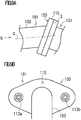
- the resin pipe member 101 for gas supply described above may be required, in some cases, to have a configuration in which a fastening surface S of a flange 103 is not orthogonal to an axis C of a shaft end portion of a pipe main body 102, for example, as shown in FIG. 9A , due to restrictions on mounting requirements.
- FIG. 9B the creep deformation at a site 115 away from fastening places 113a, 113b in the flange 103 increases. Therefore, it becomes difficult to maintain stable gas supply to an intake manifold 131 for a long period of time.
- the mold structure for molding the resin pipe member has a complicated structure using a plurality of slide molds. Incidentally, these problems occur similarly even for resin pipe members used for applications other than gas supply.
- JP HI 1-62739 A presented above discloses that a groove for absorbing the fastening load is provided in a surface opposite to the fastening surface of the flange to be fastened to the different member.
- JP 2015-105591 A discloses that a pipe main body is obliquely formed in an oil strainer made of a resin, due to restrictions on mounting requirements.
- JP HI 1-62739 A and JP 2015-105591 A nowhere disclose a configuration in which the fastening surface of the flange is not orthogonal to the axis of the shaft end portion of the pipe main body.
- An embodiment of the present invention has been made in view of the above-described circumstances, and an object of the present invention is to provide a resin pipe member which can reduce the creep deformation generated at a site apart from fastening places of a flange in a configuration in which a fastening surface of the flange is not orthogonal to an axis of a shaft end portion of a pipe main body, and which can be molded using a simple mold structure.
- a resin pipe member including: a pipe main body; and a flange formed integrally with a shaft end portion of the pipe main body to be fastened to a different member by a fastening member, wherein the flange is arranged so that its fastening surface intersects an axis of the shaft end portion of the pipe main body at an acute angle or an obtuse angle, wherein the flange is formed with a fastening surface portion forming the fastening surface, a first rib facing a surface opposite to the fastening surface of the fastening surface portion, and a plurality of second ribs causing the fastening surface portion and the first rib to communicate with each other, and wherein the first rib is provided along a plane orthogonal to the axis of the shaft end portion of the pipe main body.
- the second ribs may be provided so as to be orthogonal to the first rib and cross the first rib.
- the resin pipe member may be fastened to an intake manifold which is the different member in order to supply gas generated in an engine to the intake manifold.
- the flange may be provided with right and left fastening portions to be fastened to the different member by the fastening member with the pipe main body sandwiched therebetween, and wherein the fastening surface portion may be provided at a portion connecting the right and left fastening portions in the flange.
- first rib and the second rib may be formed in a plate-shape respective.
- the flange is arranged so that its fastening surface intersects the axis of the shaft end portion of the pipe main body at an acute or obtuse angle.
- the flange is formed with a fastening surface portion forming the fastening surface, a first rib facing a surface opposite to the fastening surface of the fastening surface portion, and a plurality of second ribs causing the fastening surface portion and the first rib to communicate with each other, and the first rib is provided along a plane orthogonal to the axis of the shaft end portion of the pipe main body.
- the creep deformation generated at a site away from the fastening places of the flange can be reduced.
- the slide molds used in the mold structure can be reduced or eliminated. Therefore, it is possible to mold the resin pipe member using a simple mold structure.
- the rigidity of the flange is further increased, so that the creep deformation generated at a site away from the fastening places of the flange can be further reduced.
- the resin pipe member when used for supplying gas generated in an engine to an intake manifold which is the different member, stable gas supply to the intake manifold can be maintained for a long period.
- the rigidity of the flange is further increased.
- the rigidity of the flange is further increased.
- the resin pipe member according to the present embodiment is a resin pipe member (1) including: a pipe main body (2) and a flange (3) formed integrally with a shaft end portion (2a) of the pipe main body (2) to be fastened to a different member (31) by fastening members (8, 9), in which the flange (3) is arranged so that its fastening surface (S) intersects an axis (C) of the shaft end portion of the pipe main body (2) at an acute or obtuse angle (see, for example, FIGS. 1 to 4 ).
- the flange (3) is formed with a fastening surface portion (10) forming the fastening surface (S), a first rib (11) facing a surface opposite to the fastening surface of the fastening surface portion, and a plurality of second ribs (12) causing the fastening surface portion and the first rib to communicate with each other.
- the first rib (11) is provided along a plane (F) orthogonal to the axis (C) of the shaft end portion of the pipe main body (2) (for example, see FIGS. 2 and 3 ).
- the flange (3) is usually arranged so that its fastening surface (S) is inclined with respect to the plane orthogonal to the axis (C) of the shaft end portion of the pipe main body (2).
- the fastening surface portion (10) can be provided at a portion in the flange (3), closer to the shaft end portion of the pipe main body (2) than the virtual plane (F).
- the resin pipe member according to the present embodiment for example, there is exemplified an aspect in which the second ribs (12) are provided so as to be orthogonal to the first rib (11) and cross the first rib (for example, see FIG. 2 ).
- the resin pipe member according to the present embodiment for example, there is exemplified an aspect in which the resin pipe member (1) is used to supply gas generated in an engine to an intake manifold (31) which is the different member (for example, see FIG. 4 ).
- a resin pipe member 1 used for supplying gas (exhaust gas, blowby gas, etc.) generated in an engine to an intake manifold 31, as shown in FIG. 4 is exemplified as the "resin pipe member" according to the present invention.
- the intake manifold 31 is made of a resin or a metal, and includes a surge tank 32 and a plurality of intake pipes 33 having one end connected to the surge tank 32 and the other end connected to the engine.
- the surge tank is provided with an attachment portion 35 to which a flange 3, which will be described below, of the resin pipe member 1 is fastened.
- the attachment portion 35 includes a tubular portion 36 and a flange 37 formed at a shaft end portion of the tubular portion 36 to abut on the flange 3 which will be described below.
- the resin pipe member 1 includes a pipe main body 2 and a flange 3 formed integrally with one shaft end portion 2a of the pipe main body 2.
- This resin pipe member 1 is provided with a flange 4 formed integrally with the other shaft end portion 2b of the pipe main body 2.
- the pipe main body 2 is formed in a substantially U-shaped tubular shape.
- An engagement portion 5 to be engaged with an engine cover (not shown) is formed integrally with an intermediate portion of the pipe main body 2.
- the flanges 3, 4 expand and extend to the outer peripheral side of the shaft end portions 2a, 2b, respectively, of the pipe main body 2, and are formed in a substantially rhombic ring shape or a substantially elliptical ring shape (that is, a substantially rhombic shape or substantially elliptical shape having a hole in the center) in plan view.
- the resin pipe member 1 is constituted by joining a pair of divided bodies 7a, 7b through welding, adhesion, or the like.
- the one divided body 7a forms the respective shaft end portions 2a, 2b of the pipe main body 2 and forms a half portion of a site causing the respective shaft end portions 2a, 2b to communicate with each other.
- the other divided body 7b forms a half portion of the site causing the respective shaft end portions 2a, 2b to communicate with each other.
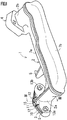
- the flange 3 is fastened to the attachment portion 35 of the intake manifold 31 by a bolt 8 and a nut 9 (exemplified as the "fastening members" according to the present invention) (see FIG. 4 ). As shown in FIGS. 2 and 3 , the flange 3 is arranged so that its fastening surface S intersects an axis C of the shaft end portion 2a of the pipe main body 2 at an acute angle ⁇ (for example, 40 to 80 degrees).
- the flange 3 is provided with a fastening surface portion 10 partially forming the fastening surface S, a plate-shaped first rib 11 facing a surface opposite to the fastening surface S of the fastening surface portion 10, and a plurality of plate-shaped second ribs 12 (three in the figure) that cause the fastening surface portion 10 and the first rib 11 to communicate with each other, and these components are integrally formed. Further, the flange 3 is provided with right and left fastening portions 13a, 13b to be fastened by the bolt 8 and the nut 9 with the pipe main body 2 sandwiched therebetween.
- the fastening surface portion 10 is provided at a portion connecting the left and right fastening portions 13a, 13b in the flange 3.
- the fastening surface portion 10 is formed in an elongated shape in a direction connecting the right and left fastening portions 13a, 13b.
- the first rib 11 is provided along a plane F orthogonal to the axis C of the shaft end portion 2a of the pipe main body 2.
- the second ribs 12 are provided so as to be orthogonal to the first rib 11 and cross the first rib 11. That is, the second ribs 12 extend to the front surface side and the back surface side of the first rib 11.
- the plurality of second ribs 12 are provided side by side along the longitudinal direction of the fastening surface portion 10.
- the flange 4 may have substantially the same configuration as that of the flange 3, or may have a different configuration from that of the flange 3.
- the plane F may or may not intersect the center of the flange 3.
- the resin pipe member 1A has substantially the same configuration as that of the resin pipe member 1 except that it has a flange 3A.
- the flange 3A is provided with a fastening surface portion 10A partially forming a fastening surface S, a plate-shaped first rib 11A facing a surface opposite to the fastening surface S of the fastening surface portion 10A, and a plurality of plate-shaped second ribs 12A (three in the figure) which cause the first rib 11A and the fastening surface portion 10A to communicate with each other, and these components are integrally formed.
- the first rib 11A is provided in parallel with the fastening surface portion 10A.
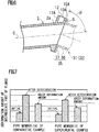
- the amounts of deformation of the intermediate portions 15, 15A apart from the left and right fastening portions 13a, 13b in the fastening surface portions 10, 10A of the flanges 3, 3A of the resin pipe members 1, 1A were measured. Specifically, the amounts of initial deformation of the intermediate portions 15, 15A immediately after fastening the resin pipe members 1, 1A to the intake manifold 31 were measured. Further, after the intake manifold 31 to which the resin pipe members 1, 1A had been fastened was left in a predetermined atmosphere (for example, an atmosphere at about 150°C) for a predetermined time (for example, 100 hours), the amounts of deformation after deterioration of the intermediate portions 15, 15A were measured. Then, the values obtained by subtracting the initial deformation amounts from the amounts of deformation after deterioration were taken as the creep deformation amounts.
- a predetermined atmosphere for example, an atmosphere at about 150°C
- a predetermined time for example, 100 hours
- the flange 3 is arranged so that its fastening surface S intersects the axis C of the shaft end portion 2a of the pipe main body 2 at an acute angle.
- the flange 3 is provided with the fastening surface portion 10 forming the fastening surface S, the first rib 11 facing the surface opposite to the fastening surface S of the fastening surface portion 10, and the plurality of second ribs 12 causing the fastening surface portion 10 and the first rib 11 to communicate with each other, and the first rib 11 is provided along the plane F orthogonal to the axis C of the shaft end portion 2a of the pipe main body 2.
- the rigidity of the flange 3 is enhanced by the first rib 11 and the second ribs 12. Therefore, in the configuration in which the fastening surface S of the flange 3 is not orthogonal to the axis C of the shaft end portion 2a of the pipe main body 2, the creep deformation generated at the site 15 apart from the fastening places 13a, 13b of the flange 3 can be reduced. Therefore, stable gas supply to the intake manifold 31 can be maintained for a long time.
- a mold structure 16A for molding the resin pipe member 1A (specifically, the half body 7a) must be provided with a slide mold 19A that slides in an oblique direction for forming the first rib 11A in addition to a pair of molds 17A, 18A that are adjacent to and apart from each other in a vertical direction (that is, a direction orthogonal to the axis C of the shaft end portion 2a of the pipe main body 2).
- the first rib 11 is formed by using a mold 17 so that the slide mold 19A is not required.
- the slide molds used in the mold structure 16 can be reduced or eliminated as compared with the resin pipe member 1A in which the first rib 11A is arranged in parallel with the fastening surface portion 10A. Therefore, the resin pipe member 1 can be molded using the simple mold structure 16.
- the second ribs 12 are provided so as to be orthogonal to the first rib 11 and cross the first rib 11.
- the rigidity of the flange 3 is further increased, so that it is possible to further reduce the creep deformation generated at the site 15 away from the fastening places 13a, 13b of the flange 3.
- the present invention is not limited to the above-described Example, and can be variously modified within the scope of the present invention depending on the purpose and application. That is, although the flange 3 formed with the single first rib 11 has been exemplified in the above Example, the present invention is not limited thereto. A flange formed with a plurality of first ribs 11 arranged in juxtaposition may be used.
- the second ribs 12 extending to cross the first rib 11 has been exemplified, but the present invention is not limited thereto.
- the second ribs 12 may extend only between the facing surfaces of the first rib 11 and the fastening surface portion 10 without extending to the side opposite to the facing surface of the first rib 11.
- the bolt 8 and the nut 9 have been exemplified as the fastening members, but the present invention is not limited thereto.
- a rivet, a clip, a grommet, or the like may be adopted as the fastening member.
- the fastening surface portion 10 forming a part of the fastening surface S has been exemplified, but the present invention is not limited thereto.
- the fastening surface portion may form the entire surface of the fastening surface S.
- the attachment portion 35 provided in the surge tank 32 of the intake manifold 31 has been exemplified, but the present invention is not limited thereto.
- the attachment portion may be provided in a gas supply passage portion formed along the plurality of intake pipes 33.
- the resin pipe member for supplying gas has been exemplified, but the present invention is not limited thereto.
- the resin pipe member may be used for supplying a liquid or utilized as a structure such as a support rod.
- the present invention is widely used as a technology relating to a resin pipe member in which a flange of a shaft end portion is fastened to a different member.
- the present resin pipe member 1 includes a pipe main body 2 and a flange 3, and the flange 3 is arranged so that its fastening surface S intersects an axis C of a shaft end portion of the pipe main body at an acute angle or an obtuse angle.
- the flange is formed with a fastening surface portion 10 forming the fastening surface, a first rib 11 facing a surface opposite to the fastening surface of the fastening surface portion, and a plurality of second ribs 12 causing the fastening surface portion and the first rib to communicate with each other, and the first rib is provided along a plane F orthogonal to the axis of the shaft end portion of the pipe main body.
Landscapes
- Engineering & Computer Science (AREA)
- General Engineering & Computer Science (AREA)
- Mechanical Engineering (AREA)
- Connection Of Plates (AREA)
- Lubrication Details And Ventilation Of Internal Combustion Engines (AREA)
- Exhaust-Gas Circulating Devices (AREA)
- Flanged Joints, Insulating Joints, And Other Joints (AREA)
Claims (5)
- Harzrohrelement (1), mit: einem Rohrhauptkörper (2); und einem Flansch (3), der einstückig mit einem Schaftendabschnitt (2a) des Rohrhauptkörpers (2) ausgebildet ist, um durch ein Befestigungselement (8, 9) an einem anderen Element (31) befestigt zu werden,
wobei der Flansch (3) so angeordnet ist, dass seine Befestigungsoberfläche (S) eine Achse (C) des Schaftendabschnitts (2a) des Rohrhauptkörpers (2) unter einem spitzen Winkel oder einem stumpfen Winkel schneidet,
wobei der Flansch (3) mit einem Befestigungsoberflächenabschnitt (10) ausgebildet ist, der die Befestigungsoberfläche (S) bildet, gekennzeichnet durch
eine erste Rippe (11), die einer Fläche zugewandt ist, die der Befestigungsfläche (S) des Befestigungsflächenabschnitts (10) gegenüberliegt, und mehrere zweite Rippen (12), die bewirken, dass der Befestigungsflächenabschnitt (10) und die erste Rippe (11) miteinander verbunden sind,
wobei die erste Rippe (11) entlang einer Ebene (F) vorgesehen ist, die rechtwinkelig zur Achse (C) des Schaftendabschnitts (2a) des Rohrhauptkörpers (2) verläuft. - Harzrohrelement (1) nach Anspruch 1, wobei die zweiten Rippen (12) so vorgesehen sind, dass sie rechtwinklig zu der ersten Rippe (11) liegen und die erste Rippe (11) kreuzen.
- Harzrohrelement (1) nach Anspruch 1 oder 2, wobei das Harzrohrelement (1) an einem Ansaugkrümmer (31) befestigt ist, der das unterschiedliche Element ist, um ein in einer Maschine erzeugtes Gas dem Ansaugkrümmer (31) zuzuführen.
- Harzrohrelement (1) nach einem der Ansprüche 1 bis 3,
wobei der Flansch (3) mit rechten und linken Befestigungsabschnitten (13a, 13b) bereitgestellt ist, die durch das Befestigungselement (8, 9) an dem unterschiedlichen Element (31) zu befestigen sind, wobei der Rohrhauptkörper (2) sandwichartig dazwischen angeordnet ist, und
wobei der Befestigungsoberflächenabschnitt (10) an einem Abschnitt vorgesehen ist, der den rechten und den linken Befestigungsabschnitt (13a, 13b) in dem Flansch (3) verbindet. - Harzrohrelement (1) nach einem der Ansprüche 1 bis 4, wobei die erste Rippe (11) und die zweite Rippe (12) jeweils plattenförmig ausgebildet sind.
Priority Applications (1)
| Application Number | Priority Date | Filing Date | Title |
|---|---|---|---|
| PL18212546T PL3521005T3 (pl) | 2018-01-31 | 2018-12-14 | Element rurowy z żywicy |
Applications Claiming Priority (1)
| Application Number | Priority Date | Filing Date | Title |
|---|---|---|---|
| JP2018015659A JP7059658B2 (ja) | 2018-01-31 | 2018-01-31 | 樹脂製パイプ部材 |
Publications (2)
| Publication Number | Publication Date |
|---|---|
| EP3521005A1 EP3521005A1 (de) | 2019-08-07 |
| EP3521005B1 true EP3521005B1 (de) | 2020-12-09 |
Family
ID=64665537
Family Applications (1)
| Application Number | Title | Priority Date | Filing Date |
|---|---|---|---|
| EP18212546.8A Active EP3521005B1 (de) | 2018-01-31 | 2018-12-14 | Harzrohrelement |
Country Status (3)
| Country | Link |
|---|---|
| EP (1) | EP3521005B1 (de) |
| JP (1) | JP7059658B2 (de) |
| PL (1) | PL3521005T3 (de) |
Family Cites Families (16)
| Publication number | Priority date | Publication date | Assignee | Title |
|---|---|---|---|---|
| JPS5210741Y2 (de) * | 1972-11-13 | 1977-03-08 | ||
| JPS5295124U (de) * | 1976-01-14 | 1977-07-16 | ||
| JPS58191485U (ja) * | 1982-06-17 | 1983-12-20 | 三菱重工業株式会社 | 異径鋼管の継手構造 |
| JPS6462739A (en) | 1987-09-03 | 1989-03-09 | Fujitsu Ltd | Fault storage address control system |
| JPH056474Y2 (de) * | 1988-02-29 | 1993-02-18 | ||
| JPH0960777A (ja) * | 1995-08-24 | 1997-03-04 | Maezawa Kasei Ind Co Ltd | 自在管継手 |
| JP3901294B2 (ja) * | 1997-08-19 | 2007-04-04 | 本田技研工業株式会社 | 樹脂製パイプ部材 |
| JP3704954B2 (ja) | 1998-06-16 | 2005-10-12 | 日産自動車株式会社 | ブローバイホースの接続構造 |
| JP2001205707A (ja) * | 2000-01-26 | 2001-07-31 | Sekisui Chem Co Ltd | フランジ付き繊維強化樹脂管 |
| JP2003294015A (ja) | 2002-03-29 | 2003-10-15 | Mahle Tennex Corp | 合成樹脂部材の締結構造 |
| US7082915B2 (en) * | 2003-04-07 | 2006-08-01 | Aisan Kogyo Kabushiki Kaisha | Resin intake manifold |
| GB0905203D0 (en) | 2009-03-26 | 2009-05-13 | Petrotechnik Ltd | Improved couplings |
| JP2015105591A (ja) | 2013-11-29 | 2015-06-08 | ダイキョーニシカワ株式会社 | オイルストレーナ |
| CN203571309U (zh) * | 2013-12-05 | 2014-04-30 | 浙江经纬集团环保工程有限公司 | 一种易安装防渗漏塑料法兰 |
| DE102014105165A1 (de) | 2014-04-11 | 2015-10-15 | Norma Germany Gmbh | Verfahren zur Herstellung eines Steckverbinders und Steckverbinder |
| US20150345678A1 (en) | 2014-05-30 | 2015-12-03 | National Diversified Sales, Inc. | Adjustable angle pipe fitting |
-
2018
- 2018-01-31 JP JP2018015659A patent/JP7059658B2/ja active Active
- 2018-12-14 EP EP18212546.8A patent/EP3521005B1/de active Active
- 2018-12-14 PL PL18212546T patent/PL3521005T3/pl unknown
Non-Patent Citations (1)
| Title |
|---|
| None * |
Also Published As
| Publication number | Publication date |
|---|---|
| JP2019132208A (ja) | 2019-08-08 |
| JP7059658B2 (ja) | 2022-04-26 |
| PL3521005T3 (pl) | 2021-05-31 |
| EP3521005A1 (de) | 2019-08-07 |
Similar Documents
| Publication | Publication Date | Title |
|---|---|---|
| EP2388455B1 (de) | Abgasturbolader | |
| JP2016020685A (ja) | 直噴エンジン用高圧燃料デリバリパイプアセンブリ | |
| US9850800B2 (en) | Exhaust system having gasket | |
| US10619540B2 (en) | Exhaust system component | |
| JP2015117590A (ja) | エンジンの排気系部品取付構造、及びエンジンの排気系部品取付方法 | |
| JP6394154B2 (ja) | 吸気装置 | |
| US6837044B2 (en) | Structure of an exhaust manifold branch collecting portion | |
| EP3521005B1 (de) | Harzrohrelement | |
| US10400716B2 (en) | Intake manifold | |
| US11073117B2 (en) | Intake manifold | |
| US7726216B2 (en) | Structural component, in particular a lubricating component | |
| JP6343444B2 (ja) | 燃料分配供給装置 | |
| US7640733B2 (en) | Structural component, especially a shielding component | |
| JP6630247B2 (ja) | 内燃機関 | |
| WO2016047015A1 (ja) | ガソリン用デリバリパイプ | |
| US10309352B2 (en) | Intake manifold | |
| US20100011755A1 (en) | Collecting part structure of exhaust manifold | |
| US20030056505A1 (en) | Exhaust gas manifold of an exhaust system for an internal combustion engine | |
| JP2001263054A (ja) | 排気管 | |
| EP2626544A1 (de) | Ansaugkrümmer | |
| US11365709B2 (en) | Component for a fuel injection system and method for manufacturing a component of a fuel injection system | |
| JP6656973B2 (ja) | インテークマニホールド | |
| JP2007278221A (ja) | 内燃機関のシール構造及びそのシール構造に使用されるガスケット | |
| JP7338672B2 (ja) | 配管取付構造およびブラケット | |
| JP2006233773A (ja) | シリンダヘッドガスケット及び多気筒エンジン |
Legal Events
| Date | Code | Title | Description |
|---|---|---|---|
| PUAI | Public reference made under article 153(3) epc to a published international application that has entered the european phase |
Free format text: ORIGINAL CODE: 0009012 |
|
| STAA | Information on the status of an ep patent application or granted ep patent |
Free format text: STATUS: REQUEST FOR EXAMINATION WAS MADE |
|
| 17P | Request for examination filed |
Effective date: 20181214 |
|
| AK | Designated contracting states |
Kind code of ref document: A1 Designated state(s): AL AT BE BG CH CY CZ DE DK EE ES FI FR GB GR HR HU IE IS IT LI LT LU LV MC MK MT NL NO PL PT RO RS SE SI SK SM TR |
|
| AX | Request for extension of the european patent |
Extension state: BA ME |
|
| GRAP | Despatch of communication of intention to grant a patent |
Free format text: ORIGINAL CODE: EPIDOSNIGR1 |
|
| STAA | Information on the status of an ep patent application or granted ep patent |
Free format text: STATUS: GRANT OF PATENT IS INTENDED |
|
| INTG | Intention to grant announced |
Effective date: 20200625 |
|
| GRAS | Grant fee paid |
Free format text: ORIGINAL CODE: EPIDOSNIGR3 |
|
| GRAA | (expected) grant |
Free format text: ORIGINAL CODE: 0009210 |
|
| STAA | Information on the status of an ep patent application or granted ep patent |
Free format text: STATUS: THE PATENT HAS BEEN GRANTED |
|
| AK | Designated contracting states |
Kind code of ref document: B1 Designated state(s): AL AT BE BG CH CY CZ DE DK EE ES FI FR GB GR HR HU IE IS IT LI LT LU LV MC MK MT NL NO PL PT RO RS SE SI SK SM TR |
|
| REG | Reference to a national code |
Ref country code: GB Ref legal event code: FG4D |
|
| REG | Reference to a national code |
Ref country code: AT Ref legal event code: REF Ref document number: 1342976 Country of ref document: AT Kind code of ref document: T Effective date: 20201215 Ref country code: CH Ref legal event code: EP |
|
| REG | Reference to a national code |
Ref country code: DE Ref legal event code: R096 Ref document number: 602018010618 Country of ref document: DE |
|
| REG | Reference to a national code |
Ref country code: IE Ref legal event code: FG4D |
|
| PG25 | Lapsed in a contracting state [announced via postgrant information from national office to epo] |
Ref country code: GR Free format text: LAPSE BECAUSE OF FAILURE TO SUBMIT A TRANSLATION OF THE DESCRIPTION OR TO PAY THE FEE WITHIN THE PRESCRIBED TIME-LIMIT Effective date: 20210310 Ref country code: NO Free format text: LAPSE BECAUSE OF FAILURE TO SUBMIT A TRANSLATION OF THE DESCRIPTION OR TO PAY THE FEE WITHIN THE PRESCRIBED TIME-LIMIT Effective date: 20210309 Ref country code: FI Free format text: LAPSE BECAUSE OF FAILURE TO SUBMIT A TRANSLATION OF THE DESCRIPTION OR TO PAY THE FEE WITHIN THE PRESCRIBED TIME-LIMIT Effective date: 20201209 Ref country code: RS Free format text: LAPSE BECAUSE OF FAILURE TO SUBMIT A TRANSLATION OF THE DESCRIPTION OR TO PAY THE FEE WITHIN THE PRESCRIBED TIME-LIMIT Effective date: 20201209 |
|
| REG | Reference to a national code |
Ref country code: AT Ref legal event code: MK05 Ref document number: 1342976 Country of ref document: AT Kind code of ref document: T Effective date: 20201209 |
|
| PG25 | Lapsed in a contracting state [announced via postgrant information from national office to epo] |
Ref country code: BG Free format text: LAPSE BECAUSE OF FAILURE TO SUBMIT A TRANSLATION OF THE DESCRIPTION OR TO PAY THE FEE WITHIN THE PRESCRIBED TIME-LIMIT Effective date: 20210309 Ref country code: LV Free format text: LAPSE BECAUSE OF FAILURE TO SUBMIT A TRANSLATION OF THE DESCRIPTION OR TO PAY THE FEE WITHIN THE PRESCRIBED TIME-LIMIT Effective date: 20201209 Ref country code: SE Free format text: LAPSE BECAUSE OF FAILURE TO SUBMIT A TRANSLATION OF THE DESCRIPTION OR TO PAY THE FEE WITHIN THE PRESCRIBED TIME-LIMIT Effective date: 20201209 |
|
| REG | Reference to a national code |
Ref country code: NL Ref legal event code: MP Effective date: 20201209 |
|
| PG25 | Lapsed in a contracting state [announced via postgrant information from national office to epo] |
Ref country code: NL Free format text: LAPSE BECAUSE OF FAILURE TO SUBMIT A TRANSLATION OF THE DESCRIPTION OR TO PAY THE FEE WITHIN THE PRESCRIBED TIME-LIMIT Effective date: 20201209 Ref country code: HR Free format text: LAPSE BECAUSE OF FAILURE TO SUBMIT A TRANSLATION OF THE DESCRIPTION OR TO PAY THE FEE WITHIN THE PRESCRIBED TIME-LIMIT Effective date: 20201209 |
|
| REG | Reference to a national code |
Ref country code: LT Ref legal event code: MG9D |
|
| PG25 | Lapsed in a contracting state [announced via postgrant information from national office to epo] |
Ref country code: LT Free format text: LAPSE BECAUSE OF FAILURE TO SUBMIT A TRANSLATION OF THE DESCRIPTION OR TO PAY THE FEE WITHIN THE PRESCRIBED TIME-LIMIT Effective date: 20201209 Ref country code: RO Free format text: LAPSE BECAUSE OF FAILURE TO SUBMIT A TRANSLATION OF THE DESCRIPTION OR TO PAY THE FEE WITHIN THE PRESCRIBED TIME-LIMIT Effective date: 20201209 Ref country code: PT Free format text: LAPSE BECAUSE OF FAILURE TO SUBMIT A TRANSLATION OF THE DESCRIPTION OR TO PAY THE FEE WITHIN THE PRESCRIBED TIME-LIMIT Effective date: 20210409 Ref country code: EE Free format text: LAPSE BECAUSE OF FAILURE TO SUBMIT A TRANSLATION OF THE DESCRIPTION OR TO PAY THE FEE WITHIN THE PRESCRIBED TIME-LIMIT Effective date: 20201209 Ref country code: CZ Free format text: LAPSE BECAUSE OF FAILURE TO SUBMIT A TRANSLATION OF THE DESCRIPTION OR TO PAY THE FEE WITHIN THE PRESCRIBED TIME-LIMIT Effective date: 20201209 Ref country code: SM Free format text: LAPSE BECAUSE OF FAILURE TO SUBMIT A TRANSLATION OF THE DESCRIPTION OR TO PAY THE FEE WITHIN THE PRESCRIBED TIME-LIMIT Effective date: 20201209 Ref country code: SK Free format text: LAPSE BECAUSE OF FAILURE TO SUBMIT A TRANSLATION OF THE DESCRIPTION OR TO PAY THE FEE WITHIN THE PRESCRIBED TIME-LIMIT Effective date: 20201209 |
|
| PG25 | Lapsed in a contracting state [announced via postgrant information from national office to epo] |
Ref country code: AT Free format text: LAPSE BECAUSE OF FAILURE TO SUBMIT A TRANSLATION OF THE DESCRIPTION OR TO PAY THE FEE WITHIN THE PRESCRIBED TIME-LIMIT Effective date: 20201209 |
|
| REG | Reference to a national code |
Ref country code: BE Ref legal event code: MM Effective date: 20201231 |
|
| REG | Reference to a national code |
Ref country code: DE Ref legal event code: R097 Ref document number: 602018010618 Country of ref document: DE |
|
| PG25 | Lapsed in a contracting state [announced via postgrant information from national office to epo] |
Ref country code: IS Free format text: LAPSE BECAUSE OF FAILURE TO SUBMIT A TRANSLATION OF THE DESCRIPTION OR TO PAY THE FEE WITHIN THE PRESCRIBED TIME-LIMIT Effective date: 20210409 Ref country code: MC Free format text: LAPSE BECAUSE OF FAILURE TO SUBMIT A TRANSLATION OF THE DESCRIPTION OR TO PAY THE FEE WITHIN THE PRESCRIBED TIME-LIMIT Effective date: 20201209 |
|
| PLBE | No opposition filed within time limit |
Free format text: ORIGINAL CODE: 0009261 |
|
| STAA | Information on the status of an ep patent application or granted ep patent |
Free format text: STATUS: NO OPPOSITION FILED WITHIN TIME LIMIT |
|
| PG25 | Lapsed in a contracting state [announced via postgrant information from national office to epo] |
Ref country code: AL Free format text: LAPSE BECAUSE OF FAILURE TO SUBMIT A TRANSLATION OF THE DESCRIPTION OR TO PAY THE FEE WITHIN THE PRESCRIBED TIME-LIMIT Effective date: 20201209 Ref country code: IE Free format text: LAPSE BECAUSE OF NON-PAYMENT OF DUE FEES Effective date: 20201214 Ref country code: LU Free format text: LAPSE BECAUSE OF NON-PAYMENT OF DUE FEES Effective date: 20201214 Ref country code: IT Free format text: LAPSE BECAUSE OF FAILURE TO SUBMIT A TRANSLATION OF THE DESCRIPTION OR TO PAY THE FEE WITHIN THE PRESCRIBED TIME-LIMIT Effective date: 20201209 |
|
| 26N | No opposition filed |
Effective date: 20210910 |
|
| PG25 | Lapsed in a contracting state [announced via postgrant information from national office to epo] |
Ref country code: DK Free format text: LAPSE BECAUSE OF FAILURE TO SUBMIT A TRANSLATION OF THE DESCRIPTION OR TO PAY THE FEE WITHIN THE PRESCRIBED TIME-LIMIT Effective date: 20201209 Ref country code: SI Free format text: LAPSE BECAUSE OF FAILURE TO SUBMIT A TRANSLATION OF THE DESCRIPTION OR TO PAY THE FEE WITHIN THE PRESCRIBED TIME-LIMIT Effective date: 20201209 |
|
| PG25 | Lapsed in a contracting state [announced via postgrant information from national office to epo] |
Ref country code: ES Free format text: LAPSE BECAUSE OF FAILURE TO SUBMIT A TRANSLATION OF THE DESCRIPTION OR TO PAY THE FEE WITHIN THE PRESCRIBED TIME-LIMIT Effective date: 20201209 |
|
| PG25 | Lapsed in a contracting state [announced via postgrant information from national office to epo] |
Ref country code: IS Free format text: LAPSE BECAUSE OF FAILURE TO SUBMIT A TRANSLATION OF THE DESCRIPTION OR TO PAY THE FEE WITHIN THE PRESCRIBED TIME-LIMIT Effective date: 20210409 Ref country code: TR Free format text: LAPSE BECAUSE OF FAILURE TO SUBMIT A TRANSLATION OF THE DESCRIPTION OR TO PAY THE FEE WITHIN THE PRESCRIBED TIME-LIMIT Effective date: 20201209 Ref country code: MT Free format text: LAPSE BECAUSE OF FAILURE TO SUBMIT A TRANSLATION OF THE DESCRIPTION OR TO PAY THE FEE WITHIN THE PRESCRIBED TIME-LIMIT Effective date: 20201209 Ref country code: CY Free format text: LAPSE BECAUSE OF FAILURE TO SUBMIT A TRANSLATION OF THE DESCRIPTION OR TO PAY THE FEE WITHIN THE PRESCRIBED TIME-LIMIT Effective date: 20201209 |
|
| PG25 | Lapsed in a contracting state [announced via postgrant information from national office to epo] |
Ref country code: MK Free format text: LAPSE BECAUSE OF FAILURE TO SUBMIT A TRANSLATION OF THE DESCRIPTION OR TO PAY THE FEE WITHIN THE PRESCRIBED TIME-LIMIT Effective date: 20201209 |
|
| PG25 | Lapsed in a contracting state [announced via postgrant information from national office to epo] |
Ref country code: BE Free format text: LAPSE BECAUSE OF NON-PAYMENT OF DUE FEES Effective date: 20201231 |
|
| REG | Reference to a national code |
Ref country code: CH Ref legal event code: PL |
|
| PG25 | Lapsed in a contracting state [announced via postgrant information from national office to epo] |
Ref country code: LI Free format text: LAPSE BECAUSE OF NON-PAYMENT OF DUE FEES Effective date: 20211231 Ref country code: CH Free format text: LAPSE BECAUSE OF NON-PAYMENT OF DUE FEES Effective date: 20211231 |
|
| PGFP | Annual fee paid to national office [announced via postgrant information from national office to epo] |
Ref country code: DE Payment date: 20251028 Year of fee payment: 8 |
|
| PGFP | Annual fee paid to national office [announced via postgrant information from national office to epo] |
Ref country code: GB Payment date: 20251030 Year of fee payment: 8 |
|
| PGFP | Annual fee paid to national office [announced via postgrant information from national office to epo] |
Ref country code: FR Payment date: 20251117 Year of fee payment: 8 |
|
| PGFP | Annual fee paid to national office [announced via postgrant information from national office to epo] |
Ref country code: PL Payment date: 20251027 Year of fee payment: 8 |