EP3518372B1 - Steuerungsvorrichtung für sekundärbatterie - Google Patents
Steuerungsvorrichtung für sekundärbatterie Download PDFInfo
- Publication number
- EP3518372B1 EP3518372B1 EP17852696.8A EP17852696A EP3518372B1 EP 3518372 B1 EP3518372 B1 EP 3518372B1 EP 17852696 A EP17852696 A EP 17852696A EP 3518372 B1 EP3518372 B1 EP 3518372B1
- Authority
- EP
- European Patent Office
- Prior art keywords
- secondary battery
- deterioration
- negative electrode
- use rate
- degree
- Prior art date
- Legal status (The legal status is an assumption and is not a legal conclusion. Google has not performed a legal analysis and makes no representation as to the accuracy of the status listed.)
- Active
Links
Images

Classifications
-
- H—ELECTRICITY
- H02—GENERATION; CONVERSION OR DISTRIBUTION OF ELECTRIC POWER
- H02J—ELECTRIC POWER NETWORKS; CIRCUIT ARRANGEMENTS OR SYSTEMS FOR SUPPLYING OR DISTRIBUTING ELECTRIC POWER; SYSTEMS FOR STORING ELECTRIC ENERGY
- H02J7/00—Circuit arrangements for charging or discharging batteries or for supplying loads from batteries
- H02J7/80—Circuit arrangements for charging or discharging batteries or for supplying loads from batteries including monitoring or indicating arrangements
- H02J7/82—Control of state of charge [SOC]
-
- G—PHYSICS
- G01—MEASURING; TESTING
- G01R—MEASURING ELECTRIC VARIABLES; MEASURING MAGNETIC VARIABLES
- G01R31/00—Arrangements for testing electric properties; Arrangements for locating electric faults; Arrangements for electrical testing characterised by what is being tested not provided for elsewhere
- G01R31/36—Arrangements for testing, measuring or monitoring the electrical condition of accumulators or electric batteries, e.g. capacity or state of charge [SoC]
- G01R31/382—Arrangements for monitoring battery or accumulator variables, e.g. SoC
- G01R31/3842—Arrangements for monitoring battery or accumulator variables, e.g. SoC combining voltage and current measurements
-
- G—PHYSICS
- G01—MEASURING; TESTING
- G01R—MEASURING ELECTRIC VARIABLES; MEASURING MAGNETIC VARIABLES
- G01R31/00—Arrangements for testing electric properties; Arrangements for locating electric faults; Arrangements for electrical testing characterised by what is being tested not provided for elsewhere
- G01R31/36—Arrangements for testing, measuring or monitoring the electrical condition of accumulators or electric batteries, e.g. capacity or state of charge [SoC]
- G01R31/392—Determining battery ageing or deterioration, e.g. state of health
-
- H—ELECTRICITY
- H01—ELECTRIC ELEMENTS
- H01M—PROCESSES OR MEANS, e.g. BATTERIES, FOR THE DIRECT CONVERSION OF CHEMICAL ENERGY INTO ELECTRICAL ENERGY
- H01M10/00—Secondary cells; Manufacture thereof
- H01M10/42—Methods or arrangements for servicing or maintenance of secondary cells or secondary half-cells
- H01M10/425—Structural combination with electronic components, e.g. electronic circuits integrated to the outside of the casing
-
- H—ELECTRICITY
- H01—ELECTRIC ELEMENTS
- H01M—PROCESSES OR MEANS, e.g. BATTERIES, FOR THE DIRECT CONVERSION OF CHEMICAL ENERGY INTO ELECTRICAL ENERGY
- H01M10/00—Secondary cells; Manufacture thereof
- H01M10/42—Methods or arrangements for servicing or maintenance of secondary cells or secondary half-cells
- H01M10/48—Accumulators combined with arrangements for measuring, testing or indicating the condition of cells, e.g. the level or density of the electrolyte
-
- H—ELECTRICITY
- H01—ELECTRIC ELEMENTS
- H01M—PROCESSES OR MEANS, e.g. BATTERIES, FOR THE DIRECT CONVERSION OF CHEMICAL ENERGY INTO ELECTRICAL ENERGY
- H01M10/00—Secondary cells; Manufacture thereof
- H01M10/42—Methods or arrangements for servicing or maintenance of secondary cells or secondary half-cells
- H01M10/48—Accumulators combined with arrangements for measuring, testing or indicating the condition of cells, e.g. the level or density of the electrolyte
- H01M10/482—Accumulators combined with arrangements for measuring, testing or indicating the condition of cells, e.g. the level or density of the electrolyte for several batteries or cells simultaneously or sequentially
-
- H—ELECTRICITY
- H01—ELECTRIC ELEMENTS
- H01M—PROCESSES OR MEANS, e.g. BATTERIES, FOR THE DIRECT CONVERSION OF CHEMICAL ENERGY INTO ELECTRICAL ENERGY
- H01M10/00—Secondary cells; Manufacture thereof
- H01M10/42—Methods or arrangements for servicing or maintenance of secondary cells or secondary half-cells
- H01M10/48—Accumulators combined with arrangements for measuring, testing or indicating the condition of cells, e.g. the level or density of the electrolyte
- H01M10/486—Accumulators combined with arrangements for measuring, testing or indicating the condition of cells, e.g. the level or density of the electrolyte for measuring temperature
-
- H—ELECTRICITY
- H02—GENERATION; CONVERSION OR DISTRIBUTION OF ELECTRIC POWER
- H02J—ELECTRIC POWER NETWORKS; CIRCUIT ARRANGEMENTS OR SYSTEMS FOR SUPPLYING OR DISTRIBUTING ELECTRIC POWER; SYSTEMS FOR STORING ELECTRIC ENERGY
- H02J7/00—Circuit arrangements for charging or discharging batteries or for supplying loads from batteries
- H02J7/80—Circuit arrangements for charging or discharging batteries or for supplying loads from batteries including monitoring or indicating arrangements
-
- H—ELECTRICITY
- H02—GENERATION; CONVERSION OR DISTRIBUTION OF ELECTRIC POWER
- H02J—ELECTRIC POWER NETWORKS; CIRCUIT ARRANGEMENTS OR SYSTEMS FOR SUPPLYING OR DISTRIBUTING ELECTRIC POWER; SYSTEMS FOR STORING ELECTRIC ENERGY
- H02J7/00—Circuit arrangements for charging or discharging batteries or for supplying loads from batteries
- H02J7/80—Circuit arrangements for charging or discharging batteries or for supplying loads from batteries including monitoring or indicating arrangements
- H02J7/84—Control of state of health [SOH]
-
- H—ELECTRICITY
- H01—ELECTRIC ELEMENTS
- H01M—PROCESSES OR MEANS, e.g. BATTERIES, FOR THE DIRECT CONVERSION OF CHEMICAL ENERGY INTO ELECTRICAL ENERGY
- H01M10/00—Secondary cells; Manufacture thereof
- H01M10/42—Methods or arrangements for servicing or maintenance of secondary cells or secondary half-cells
- H01M10/425—Structural combination with electronic components, e.g. electronic circuits integrated to the outside of the casing
- H01M2010/4271—Battery management systems including electronic circuits, e.g. control of current or voltage to keep battery in healthy state, cell balancing
-
- Y—GENERAL TAGGING OF NEW TECHNOLOGICAL DEVELOPMENTS; GENERAL TAGGING OF CROSS-SECTIONAL TECHNOLOGIES SPANNING OVER SEVERAL SECTIONS OF THE IPC; TECHNICAL SUBJECTS COVERED BY FORMER USPC CROSS-REFERENCE ART COLLECTIONS [XRACs] AND DIGESTS
- Y02—TECHNOLOGIES OR APPLICATIONS FOR MITIGATION OR ADAPTATION AGAINST CLIMATE CHANGE
- Y02E—REDUCTION OF GREENHOUSE GAS [GHG] EMISSIONS, RELATED TO ENERGY GENERATION, TRANSMISSION OR DISTRIBUTION
- Y02E60/00—Enabling technologies; Technologies with a potential or indirect contribution to GHG emissions mitigation
- Y02E60/10—Energy storage using batteries
Definitions
- the present invention relates to a secondary battery control device.
- PTL 1 describes a technology for knowing states of a charge and discharge curve of a whole positive electrode and a charge and discharge curve of a whole negative electrode inside the secondary battery in a nondestructive manner.
- a discharge capacity of a battery is determined according to member factors such as an effective positive electrode active material amount, an effective negative electrode active material amount, and a positional relationship between a positive electrode and a negative electrode, and these values are expressed by functions with variables such as a use period, a temperature, and a voltage.
- Deterioration states of the member factors of the secondary battery are estimated on the basis of the functions.
- WO 2015/019427 A1 provides are a more appropriate charge and discharge control method for a lithium ion secondary battery and a battery system using the charge and discharge control method.
- the battery system of the present invention has: a lithium ion secondary battery that houses a winding body; a controller that gives charging and discharging instructions; and a charge and discharge control device that outputs a charge and discharge control signal to the controller to control the charging and discharging of the lithium ion secondary battery.
- the charge and discharge control device has: a battery information acquiring unit; a side reaction amount calculation unit for, based on the battery information acquired by the battery information acquiring unit, calculating the side reaction amount of the battery; a calculation unit for, based on the calculated side reaction amount, calculating a charging upper limit voltage; and a control signal transmission unit for, based on the calculated charging upper limit voltage, outputting the charge and discharge control signal to the controller.
- the calculation unit calculates a new charging upper limit voltage by adding a predetermined percentage of the side reaction amount to an initial charging upper limit voltage and, when the side reaction amount exceeds a threshold value, sets the new charging upper limit voltage as a charging upper limit voltage.
- the apparatus for controlling operation of a storage battery of the present invention comprises: a component deterioration index measuring part, which measures a deterioration index with respect to each of predetermined components of a storage battery; a deterioration condition determination part, which determines deterioration condition with respect to each of the predetermined components, based on the deterioration indices of the components measured by the component deterioration index measuring part: an operation condition determination part, which determines such an operation condition of the storage battery as would cause deterioration of each component to progress in a manner such that the longest battery life is achieved, based on the deterioration conditions determined by the deterioration determination part; and an operation control part for operating the storage battery based on the operation condition determined by the operation condition determination part.
- an apparatus provides real-time monitoring of voltage and differential voltage of both anode and cathode in a battery configured with at least one reference electrode.
- Voltage monitors are connected to a computer programmed for receiving anode voltage signals; receiving cathode voltage signals; calculating the derivative of the anode voltage with respect to time or with respect to capacity; and calculating the derivative of the cathode voltage with respect to time or with respect to capacity.
- an electric vehicle consists of a first memory section for storing a displacement behavior map indicating a correspondence relationship between a displacement behavior per unit time of an AC impedance value according to a frequency having a relationship with a deterioration degree and a capacity retaining rate for respective positive and negative electrodes and each electrolyte of a battery, and a using history based on a state of the battery; a correlation resistance value estimation section for estimating a positive electrode side correlation resistance value and a negative electrode side correlation resistance value of the battery by referring to the displacement behavior map according to the using history of the battery; and a target charging state setting section for calculating a deterioration balance indicating a balance between a deterioration state of the positive electrode and a deterioration state of the negative electrode of the battery, based on the positive electrode side correlation resistance value and the negative electrode side correlation resistance value, to set a target charging state based on the deterioration balance.
- a secondary battery control device to solve the above issue is a secondary battery control device according to independent claim 1.
- the dependent claims refer to preferred embodiments of the present invention.
- the life of the secondary battery can be prolonged by performing control according to the deterioration of the secondary battery.
- the charge and discharge curve of the secondary battery obtained in a case where charge and discharge of the secondary battery is performed with a minute current is favorably reproduced by performing superposition calculation of separately measured charge and discharge curves of the positive electrode alone and the negative electrode alone. Then, as parameters to be used for this calculation, the positive electrode active material amount contributing to the charge and discharge, the negative electrode active material amount contributing to the charge and discharge, and an index of the positional relationship between the charge and discharge curves of the positive electrode and the negative electrode are determined.
- a use rate of the positive electrode active material amount is described as a positive electrode use rate
- a use rate of the negative electrode active material amount is described as a negative electrode use rate
- the index of the positional relationship between the charge and discharge curves of the positive electrode and the negative electrode is described as a negative electrode capacity deviation.
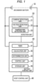
- FIG. 1 is a diagram illustrating a secondary battery system.
- the secondary battery system includes a secondary battery 10, a detection unit 20, a battery control unit 30, and a hostcontrol unit 40.
- the secondary battery 10 is configured by connecting a plurality of cells in series. Note that although FIG. 1 illustrates an example in which a plurality of cells is connected in series, cells connected in series may be further provided in parallel.
- the secondary battery 10 is used, for example, as a power source of a vehicle traveling motor.
- the detection unit 20 includes a current detection unit 21 that detects a current flowing through the secondary battery 10, a voltage detection unit 22 that detects a voltage of the secondary battery 10, a temperature detection unit 23 that detects a temperature of the secondary battery 10.
- the battery control unit 30 includes a timer 31, a calculation unit 32, a determination unit 33, a control unit 34, and a storage unit 35.
- the current detected by the current detection unit 21, the voltage detected by the voltage detection unit 22, and the temperature detected by the temperature detection unit 23 are input to the battery control unit 30. Further, the battery control unit 30 controls a charge and discharge state of the secondary battery 10 according to a predetermined operation condition.
- the calculation unit 32 calculates the degree of deterioration for each member factor of the secondary battery 10, for example, the positive electrode use rate, the negative electrode use rate, and the negative electrode capacity deviation on the basis of first prediction expressions to be described below.
- the determination unit 33 determines a deteriorated member factor of the secondary battery 10 on the basis of a calculation result by the calculation unit 32.
- the control unit 34 changes the operation condition of the secondary battery 10 according to the deteriorated member factor. As the change of the operating condition, for example, the secondary battery 10 is operated at a high voltage, or an upper limit current of the secondary battery 10 is lowered and the secondary battery 10 is operated. The control unit 34 controls the charge and discharge state of the secondary battery 10 according to the operating condition.
- the storage unit 35 stores a function of a use time and an ideal degree of deterioration of the secondary battery 10 as a second prediction expression in advance.
- This second prediction expression indicates transition of an ideal degree of deterioration of the secondary battery 10, and is a predefined function in accordance with a use form of the secondary battery. Note that the relationship between the use time and the degree of deterioration of the secondary battery 10 is not limited to the function and may be stored as a table in advance.
- the host control unit 40 is connected to the battery control unit 30 and instructs the battery control unit 30 to issue commands of charge and discharge and the like.
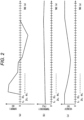
- FIG. 2 is a graph illustrating measurement examples of the secondary battery 10 by the detection unit 20.
- FIG. 2(a) illustrates the current
- FIG. 2(b) illustrates the temperature
- FIG. 2(c) illustrates the voltage.
- the horizontal axis of each graph represents time, and values measured at time t 1 intervals are plotted into the graphs.
- a current I flowing through the secondary battery 10 is initially 0, then rapidly flows in a plus direction, and then gradually decreases. Thereafter, the current I flows in a minus direction, and gradually approaches 0.
- the temperature T of the secondary battery 10 slightly rises over time.
- a voltage V of the secondary battery 10 is initially high, and then transitions to be low and high again.
- the graphs illustrated in FIGS. 2(a), 2(b) and 2(c) are examples for describing the present embodiment, and other measured values may be used. These measured values are detected by the current detection unit 21, the voltage detection unit 22, and the temperature detection unit 23 at every time t 1 defined by the timer 31 of the battery control unit 30, and the values are sent to the battery control unit 30.
- the calculation unit 32 of the battery control unit 30 calculates a positive electrode use rate mp1, a negative electrode use rate mn1, and a negative electrode capacity deviation dn1 by the following first prediction expressions (1) to (3).
- f1, g1, and h1 are functions with the current I, the voltage V, the temperature T, and the time t as variables.
- the current I, the voltage V, and the temperature T are values detected by the current detection unit 21, the voltage detection unit 22, and the temperature detection unit 23, respectively. From these first prediction expressions (1) to (3), the positive electrode use rate mp1, the negative electrode use rate mn1, and the negative electrode capacity deviation dn1 at every time t 1 are obtained.
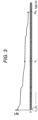
- FIG. 3 is a graph illustrating an example of transition of the positive electrode use rate mp1 calculated at every time t 1 .
- the horizontal axis represents time
- a time t 2 is a time interval longer than the time t 1 .
- This example illustrates the positive electrode use rate mp1 gradually lowers (is deteriorated).
- graphs illustrating transition of the negative electrode use rate mn1 and the negative electrode capacity deviation dn1 are omitted, the negative electrode use rate mn1 gradually lowers (is deteriorated) over time, and the negative electrode capacity deviation dn1 gradually rises (is deteriorated).
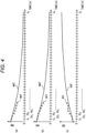
- FIG. 4(a) is a graph illustrating an example of transition of the positive electrode use rate mp at every time t 2
- FIG. 4(b) is a graph illustrating an example of transition of the negative electrode use rate mn
- FIG. 4(c) is a graph illustrating an example of transition of the negative electrode capacity deviation.
- the circles in the figures illustrate degrees of deterioration at the time t 2 intervals based on measured values calculated by the first prediction expressions, that is, the positive electrode use rate mp1, the negative electrode use rate mn1, and the negative electrode capacity deviation dn1, respectively.
- the solid lines in the figures illustrate transition of ideal degrees of deterioration based on the second prediction expressions.
- the ideal degrees of deterioration are defined by the following second prediction expressions (4) to (6).
- f2, g2, and h2 are functions with the time t as a variable. From these second prediction expressions (4) to (6), a positive electrode use rate mp2, a negative electrode use rate mn2, and a negative electrode capacity deviation dn2 indicating the ideal degrees of deterioration at every time t 2 are obtained.
- the second prediction expressions (4) to (6) express, for example, ideal deterioration transitions that become desired degrees of deterioration at a time t 3 . Note that the time t 2 ⁇ the time t 3 .
- the degree of deterioration of the positive electrode use rate mp1 based on the measured value calculated by the first prediction expression is larger than the ideal degree of deterioration of the positive electrode use rate mp2 based on the second prediction expression.
- the deterioration degree of the negative electrode use rate mn1 based on the measured value calculated by the first prediction expression is larger than the ideal degree of deterioration of the negative electrode use rate mn2 based on the second prediction expression.
- the degree of deterioration of the negative electrode capacity deviation dn1 based on the measured value calculated by the first prediction expression is larger than the ideal degree of deterioration of the negative electrode capacity deviation dn2 based on the second prediction expression.
- the operating condition of the secondary battery 10 is changed according to the deteriorated member factor, for example, the positive electrode use rate, the negative electrode use rate, or the negative electrode capacity deviation.
- the flowchart of FIG. 5 illustrates a processing operation periodically executed by the battery control unit 30. Note that a part of the processing operation illustrated in this flowchart may be performed by the host control unit 40.
- step S11 in FIG. 5 the state of the secondary battery 10 is detected at the time t 1 second intervals. Specifically, when t 1 seconds have elapsed from previous detection by the timer 31, the current detection unit 21 detects the current, the voltage detection unit 22 detects the voltage, and the temperature detection unit 23 detects the temperature.
- step S12 the degrees of deterioration at the time t 1 are calculated by the first prediction expressions (1) to (3). Specifically, the positive electrode use rate mp1, the negative electrode use rate mn1, and the negative electrode capacity deviation dn1 are calculated by the first prediction expressions (1) to (3) on the basis of the current, the voltage, and the temperature detected in step S11. In step S12, the degrees of deterioration calculated at the time t 1 second intervals are stored in the storage unit 35.
- step S13 whether i ⁇ t 1 is larger than t 2 is determined.
- i is a positive integer. That is, whether the calculation at the time t 1 intervals is performed i times and the time t 2 has passed is determined.
- i is incremented by 1 in step S14, and the processing returns to step S11.
- the processing proceeds to step S15.
- step S15 an average value of the degrees of deterioration calculated at the time t 1 second intervals up to the time t 2 and stored in the storage unit 35. That is, average values of the positive electrode use rates mp1, the negative electrode use rates mn1, and the negative electrode capacity deviations dn1 are calculated.
- step S16 i is updated to zero. Then, the degrees of deterioration at the time t 2 is calculated by the second prediction expressions (4) to (6). Specifically, the positive electrode use rate mp2, negative electrode use rate mn2, and negative electrode capacity deviation dn2 at the time t 2 are calculated on the basis of the second prediction expressions (4) to (6). The calculated degrees of deterioration are stored in the storage unit 35.
- step S17 the determination unit 33 determines whether a difference between the average value of the negative electrode capacity deviations dn1 calculated in step S15 and the negative electrode capacity deviation dn2 calculated in step S16 is larger than a predetermined value D.
- the example illustrated in FIG. 4(c) is a case where the degree of deterioration of the negative electrode capacity deviation dn1 is large.
- the mainly deteriorated member factor in the secondary battery 10 is determined to be the negative electrode capacity deviation, and the processing proceeds to next step S18.
- step S18 the control unit 34 controls the secondary battery 10 to operate at a high voltage. With the control, the deterioration of the negative electrode capacity deviation dn1 is suppressed and the life of the secondary battery 10 is prolonged. In a case where the difference between the average value of the negative electrode capacity deviations dn1 and the negative electrode capacity deviation dn2 is determined not to be larger than the value D in step S17, the processing proceeds to step S19.
- step S19 the determination unit 33 determines whether the positive electrode use rate mp2 calculated in step S16 and the average value of the positive electrode use rates mp1 calculated in step S15 is larger than a predetermined value A.
- the example illustrated in FIG. 4(a) is a case where the degree of deterioration of the positive electrode use rate mp1 is large.
- the mainly deteriorated member factor in the secondary battery 10 is determined to be the positive electrode use rate, and the processing proceeds to next step S20.
- step S20 the control unit 34 lowers the upper limit current of the secondary battery 10 and controls the secondary battery 10 to operate. With the control, the deterioration of the positive electrode use rate mp1 is suppressed, and the life of the secondary battery 10 is prolonged.
- the processing proceeds to step S21.
- step S21 the determination unit 33 determines whether a difference between the negative electrode use rate mn2 calculated in step S16 and the average value of the negative electrode use rates mn1 calculated in step S15 is larger than a predetermined value B.
- the example illustrated in FIG. 4(b) is a case where the degree of deterioration of the negative electrode use rate mn1 is large.
- the mainly deteriorated member factor in the secondary battery 10 is determined to be the negative electrode use rate, and the processing proceeds to next step S22.
- step S22 the control unit 34 lowers the upper limit current of the secondary battery 10 and controls the secondary battery 10 to operate. Further, the control unit 34 controls the secondary battery 10 to operate at a high voltage. With the control, the deterioration of the negative electrode use rate mn1 is suppressed and the life of the secondary battery 10 is prolonged.
- step S21 in a case where the difference between the negative electrode use rate mn2 and the average value of the negative electrode use rates mn1 is determined not to be larger than the value B, and the processing in steps S18, S20, and S22 is terminated, the flowchart illustrated in FIG. 5 is terminated.
- step S15 the average values of the positive electrode use rate mp1, the negative electrode use rate mn1, and the negative electrode capacity deviation dn1 have been calculated, and in steps S17, S19, and S21, these average values and the positive electrode use rate mp2, the negative electrode use rate mn2, and the negative electrode capacity deviation dn2 have been compared.
- the degrees of deteriorations at the time t 2 may be calculated by the first prediction expressions (1) to (3) and the calculated values, instead of calculating the average values, and the positive electrode use rate mp2, the negative electrode use rate mn2, and the negative electrode capacity deviation dn2 may be compared.
- the battery control unit 30 includes the calculation unit 32 that calculates the degree of deterioration of the secondary battery 10 for each of the member factors of the secondary battery 10, for example, the positive electrode use rate, the negative electrode use rate, and the negative electrode capacity deviation, the determination unit 33 that determines the deteriorated member factor, of the member factors of the secondary battery 10, on the basis of the calculation result of the calculation unit 32, and the control unit 34 that changes the operating condition of the secondary battery 10 according to the deteriorated member factor.
- the life of the secondary battery 10 can be prolonged by performing control according to the deterioration of the secondary battery 10.
- the present invention can be implemented by modifying the above-described embodiment as follows.
- (1) The positive electrode use rate, the negative electrode use rate, and the negative electrode capacity deviation have been exemplarily described as the member factors of the secondary battery.
- the embodiment is not limited to the example, and a deviation amount of a positive electrode voltage, a coefficient that is a parameter related to positive electrode resistance of the secondary battery, a coefficient that is a parameter related to a negative electrode resistance of the secondary battery, or a coefficient related to another resistance component may be employed as the member factor of the secondary battery.
- the embodiment is not limited to the example, and a starting voltage, an ending voltage, a maximum voltage, a minimum voltage, an ambient temperature, a charge capacity, a discharge capacity, electric quantity fluctuation per unit time, a maximum current, an average current, a lower limit current, an operation center voltage, a residence time ratio in each voltage domain, an energization polarity ratio per unit time, an energization time ratio, a pause time ratio, upper and lower limit voltages, an SOC fluctuation width, an energization time, and the like may be used as the operating condition.
- the present invention is not limited to the above-described embodiments, and other forms conceivable within the technical idea of the present invention are also included in the scope of the present invention unless the characteristics of the present invention are impaired. Further, a configuration of a combination of the above-described embodiment and a plurality of modifications may be adopted.
Landscapes
- Engineering & Computer Science (AREA)
- General Chemical & Material Sciences (AREA)
- Manufacturing & Machinery (AREA)
- Chemical & Material Sciences (AREA)
- Chemical Kinetics & Catalysis (AREA)
- Electrochemistry (AREA)
- Physics & Mathematics (AREA)
- General Physics & Mathematics (AREA)
- Power Engineering (AREA)
- Microelectronics & Electronic Packaging (AREA)
- Secondary Cells (AREA)
- Tests Of Electric Status Of Batteries (AREA)
- Charge And Discharge Circuits For Batteries Or The Like (AREA)
Claims (6)
- Sekundärbatterie-Steuervorrichtung (30) für ein elektrisches Fahrzeug, die Folgendes umfasst:eine Verschlechterungsgrad-Berechnungseinheit (32), die konfiguriert ist, den Verschlechterungsgrad einer Sekundärbatterie (10) für jeden von mehreren Elementfaktoren der Sekundärbatterie (10) zu berechnen;eine Bestimmungseinheit (33), die konfiguriert ist, auf der Grundlage eines Berechnungsergebnisses der Verschlechterungsgrad-Berechnungseinheit (32) einen verschlechterten Elementfaktor der mehreren Elementfaktoren der Sekundärbatterie (10) zu bestimmen; undeine Steuereinheit (34), die konfiguriert ist, ein Betriebsbedingung der Sekundärbatterie (10) gemäß dem verschlechterten Elementfaktor zu ändern,dadurch gekennzeichnet, dass:die mehreren Elementfaktoren zumindest eine Nutzungsrate der positiven Elektrode, eine Nutzungsrate der negativen Elektrode und eine Kapazitätsabweichung der negativen Elektrode sind, unddie Nutzungsrate der positiven Elektrode eine Nutzungsrate der Menge des aktiven Materials der positiven Elektrode ist, die Nutzungsrate der negativen Elektrode eine Nutzungsrate der Menge des aktiven Materials der negativen Elektrode ist und die Kapazitätsabweichung der negativen Elektrode ein Index der Positionsbeziehung zwischen den Ladungs- und Entladungskurven der positiven Elektrode und der negativen Elektrode ist; unddann, wenn der verschlechterte Elementfaktor die Nutzungsrate der positiven Elektrode ist, die Steuereinheit (34) konfiguriert ist, die Betriebsbedingung der Sekundärbatterie (10) durch Absenken eines oberen Stromgrenzwertes zu ändern und die Sekundärbatterie (10) zu betreiben.
- Sekundärbatterie-Steuervorrichtung (30) nach Anspruch 1, wobei
dann, wenn der verschlechterte Elementfaktor die Kapazitätsabweichung der negativen Elektrode ist, die Steuereinheit (34) konfiguriert ist, die Sekundärbatterie (10) mit einer hohen Spannung als die Betriebsbedingung der Sekundärbatterie (10) zu betreiben. - Sekundärbatterie-Steuervorrichtung (30) nach einem der Ansprüche 1 bis 2, wobei
dann, wenn der verschlechterte Elementfaktor die Nutzungsrate der negativen Elektrode ist, die Steuereinheit (34) konfiguriert ist, den oberen Stromgrenzwert der Sekundärbatterie (10) abzusenken und die Sekundärbatterie (10) mit einer hohen Spannung als die Betriebsbedingungen der Sekundärbatterie (10) zu betreiben. - Sekundärbatterie-Steuervorrichtung (30) nach Anspruch 1, wobeidie Verschlechterungsgrad-Berechnungseinheit (32) konfiguriert ist, eine Differenz zwischen einem aktuellen Verschlechterungsgrad und einem vorab definierten Verschlechterungsgrad für jeden Elementfaktor der Sekundärbatterie (10) zu berechnen, unddie Bestimmungseinheit (33) konfiguriert ist, einen Elementfaktor, bei dem die Differenz zwischen dem aktuellen Verschlechterungsgrad und dem vorab definierten Verschlechterungsgrad einen vorgegebenen Wert überschreitet, als den verschlechterten Elementfaktor zu bestimmen.
- Sekundärbatterie-Steuervorrichtung (30) nach Anspruch 4, wobei
die Verschlechterungsgrad-Berechnungseinheit (32) konfiguriert ist, den aktuellen Verschlechterungsgrad auf der Grundlage einer Nutzungszeit der Sekundärbatterie (10), eines Stromwertes, eines Spannungswertes und einer Temperatur der Sekundärbatterie (10) zu berechnen. - Sekundärbatterie-Steuervorrichtung (30) nach Anspruch 4 oder 5, wobei
die Verschlechterungsgrad-Berechnungseinheit (32) konfiguriert ist, den vorab definierten Verschlechterungsgrad als eine Funktion der Nutzungszeit und des Verschlechterungsgrads der Sekundärbatterie (10) zu definieren.
Applications Claiming Priority (2)
| Application Number | Priority Date | Filing Date | Title |
|---|---|---|---|
| JP2016184735A JP6602735B2 (ja) | 2016-09-21 | 2016-09-21 | 二次電池制御装置 |
| PCT/JP2017/027609 WO2018055915A1 (ja) | 2016-09-21 | 2017-07-31 | 二次電池制御装置 |
Publications (3)
| Publication Number | Publication Date |
|---|---|
| EP3518372A1 EP3518372A1 (de) | 2019-07-31 |
| EP3518372A4 EP3518372A4 (de) | 2020-03-11 |
| EP3518372B1 true EP3518372B1 (de) | 2025-04-23 |
Family
ID=61689442
Family Applications (1)
| Application Number | Title | Priority Date | Filing Date |
|---|---|---|---|
| EP17852696.8A Active EP3518372B1 (de) | 2016-09-21 | 2017-07-31 | Steuerungsvorrichtung für sekundärbatterie |
Country Status (5)
| Country | Link |
|---|---|
| US (1) | US11346890B2 (de) |
| EP (1) | EP3518372B1 (de) |
| JP (1) | JP6602735B2 (de) |
| CN (1) | CN109511281B (de) |
| WO (1) | WO2018055915A1 (de) |
Families Citing this family (7)
| Publication number | Priority date | Publication date | Assignee | Title |
|---|---|---|---|---|
| CN109821775A (zh) * | 2019-01-09 | 2019-05-31 | 中兴高能技术有限责任公司 | 一种筛选电池的方法、终端和存储介质 |
| KR102871577B1 (ko) | 2019-09-04 | 2025-10-17 | 삼성전자주식회사 | 배터리 충전 장치 및 방법 |
| US11255919B2 (en) * | 2019-09-12 | 2022-02-22 | Semiconductor Components Industries, Llc | Methods and system for a battery |
| JP7225153B2 (ja) * | 2020-03-13 | 2023-02-20 | 株式会社東芝 | 充放電制御方法、電池搭載機器、管理システム、充放電制御プログラム、管理方法、管理サーバ及び管理プログラム |
| EP4145586B1 (de) * | 2020-04-27 | 2026-04-15 | Nissan Motor Co., Ltd. | Ausgabesteuerungsverfahren für sekundärbatterie und ausgabesteuerungssystem für sekundärbatterie |
| JP7622363B2 (ja) * | 2020-06-30 | 2025-01-28 | 株式会社デンソー | 二次電池の劣化度判定装置 |
| US12117501B2 (en) * | 2020-10-27 | 2024-10-15 | Lg Energy Solution, Ltd. | Battery management apparatus and method |
Citations (1)
| Publication number | Priority date | Publication date | Assignee | Title |
|---|---|---|---|---|
| US20120105069A1 (en) * | 2010-11-01 | 2012-05-03 | Gm Global Technology Operations, Inc. | Method and apparatus for assessing battery state of health |
Family Cites Families (12)
| Publication number | Priority date | Publication date | Assignee | Title |
|---|---|---|---|---|
| EP1933158B1 (de) * | 2005-09-16 | 2018-04-25 | The Furukawa Electric Co., Ltd. | Verfahren und einrichtung zur beurteilung einer sekundärzellenverschlechterung und stromversorgungssystem |
| JP4042917B1 (ja) * | 2007-04-23 | 2008-02-06 | 株式会社パワーシステム | キャパシタ電源の異常判別方法及び異常判別装置 |
| EP2053414B1 (de) | 2007-09-07 | 2013-07-03 | Hitachi Vehicle Energy, Ltd. | Verfahren und Vorrichtung zur Erkennung interner Informationen einer Sekundärbatterie |
| JP4884404B2 (ja) | 2007-09-07 | 2012-02-29 | 日立ビークルエナジー株式会社 | 二次電池の内部情報検知方法及び装置 |
| JP5341823B2 (ja) * | 2010-06-07 | 2013-11-13 | トヨタ自動車株式会社 | リチウムイオン二次電池の劣化判定システムおよび劣化判定方法 |
| JP5453232B2 (ja) | 2010-12-24 | 2014-03-26 | 本田技研工業株式会社 | 電動車両 |
| JP5660003B2 (ja) * | 2011-10-24 | 2015-01-28 | トヨタ自動車株式会社 | 二次電池の劣化状態判別システム及び劣化状態判別方法。 |
| KR20150058172A (ko) * | 2012-09-20 | 2015-05-28 | 세키스이가가쿠 고교가부시키가이샤 | 축전지 운전 제어 장치, 축전지 운전 제어 방법 및 프로그램 |
| JP6122594B2 (ja) * | 2012-09-20 | 2017-04-26 | 積水化学工業株式会社 | 蓄電池管理装置、蓄電池管理方法及びプログラム |
| JP5765375B2 (ja) | 2013-07-25 | 2015-08-19 | トヨタ自動車株式会社 | 制御装置及び制御方法 |
| WO2015019427A1 (ja) * | 2013-08-07 | 2015-02-12 | 株式会社日立製作所 | 電池システム |
| US9742042B2 (en) * | 2013-11-23 | 2017-08-22 | Hrl Laboratories, Llc | Voltage protection and health monitoring of batteries with reference electrodes |
-
2016
- 2016-09-21 JP JP2016184735A patent/JP6602735B2/ja active Active
-
2017
- 2017-07-31 WO PCT/JP2017/027609 patent/WO2018055915A1/ja not_active Ceased
- 2017-07-31 EP EP17852696.8A patent/EP3518372B1/de active Active
- 2017-07-31 CN CN201780045447.2A patent/CN109511281B/zh active Active
- 2017-07-31 US US16/328,363 patent/US11346890B2/en active Active
Patent Citations (1)
| Publication number | Priority date | Publication date | Assignee | Title |
|---|---|---|---|---|
| US20120105069A1 (en) * | 2010-11-01 | 2012-05-03 | Gm Global Technology Operations, Inc. | Method and apparatus for assessing battery state of health |
Non-Patent Citations (1)
| Title |
|---|
| HAN XUEBING ET AL: "A comparative study of commercial lithium ion battery cycle life in electrical vehicle: Aging mechanism identification", JOURNAL OF POWER SOURCES, ELSEVIER, AMSTERDAM, NL, vol. 251, 23 November 2013 (2013-11-23), pages 38 - 54, XP028807460, ISSN: 0378-7753, DOI: 10.1016/J.JPOWSOUR.2013.11.029 * |
Also Published As
| Publication number | Publication date |
|---|---|
| US11346890B2 (en) | 2022-05-31 |
| EP3518372A1 (de) | 2019-07-31 |
| CN109511281A (zh) | 2019-03-22 |
| US20210286014A1 (en) | 2021-09-16 |
| EP3518372A4 (de) | 2020-03-11 |
| JP2018050405A (ja) | 2018-03-29 |
| JP6602735B2 (ja) | 2019-11-06 |
| WO2018055915A1 (ja) | 2018-03-29 |
| CN109511281B (zh) | 2022-12-13 |
Similar Documents
| Publication | Publication Date | Title |
|---|---|---|
| EP3518372B1 (de) | Steuerungsvorrichtung für sekundärbatterie | |
| US10955479B2 (en) | Battery control device | |
| EP3506452B1 (de) | Batterieladeverfahren und - vorrichtung | |
| JP5994240B2 (ja) | 組電池の制御装置 | |
| KR102259967B1 (ko) | 배터리 충전관리 장치 및 방법 | |
| KR102153888B1 (ko) | 계단 충전 | |
| EP3958006A1 (de) | Batteriediagnosevorrichtung und -verfahren | |
| US10359474B2 (en) | Charge state calculation device and charge state calculation method | |
| US10014706B2 (en) | Model-based fast-charging method based on lithium surface concentration | |
| CN104115017B (zh) | 电池系统以及劣化判别方法 | |
| JP6500789B2 (ja) | 二次電池の制御システム | |
| KR20190045736A (ko) | 배터리 충전 방법 및 장치 | |
| JP7207817B2 (ja) | バッテリー管理方法、バッテリー装置、およびバッテリーを含む自動車 | |
| KR20180115124A (ko) | 노이즈를 반영한 배터리 잔존 용량 산출 장치 및 방법 | |
| JP2015230817A (ja) | 二次電池システムおよび二次電池の制御方法 | |
| JP7115035B2 (ja) | 電池寿命推定装置 | |
| CN106662620A (zh) | 电池状态探测装置、二次电池系统、程序产品、电池状态探测方法 | |
| JP5716691B2 (ja) | 電池システムおよび非水二次電池の充放電制御方法 | |
| WO2018211824A1 (ja) | 電池制御装置および車両システム | |
| KR20180057275A (ko) | 배터리 제어 방법 및 장치 | |
| CN115833294A (zh) | 自动化参考电极管理 | |
| CN119013573A (zh) | 智能电池管理系统和方法 | |
| WO2019194205A1 (ja) | 二次電池の診断装置及び診断方法 | |
| JP2023528403A (ja) | バッテリー診断装置、バッテリー診断方法、バッテリーパック及び電気車両 | |
| US20160104924A1 (en) | Secondary Battery System |
Legal Events
| Date | Code | Title | Description |
|---|---|---|---|
| STAA | Information on the status of an ep patent application or granted ep patent |
Free format text: STATUS: THE INTERNATIONAL PUBLICATION HAS BEEN MADE |
|
| PUAI | Public reference made under article 153(3) epc to a published international application that has entered the european phase |
Free format text: ORIGINAL CODE: 0009012 |
|
| STAA | Information on the status of an ep patent application or granted ep patent |
Free format text: STATUS: REQUEST FOR EXAMINATION WAS MADE |
|
| 17P | Request for examination filed |
Effective date: 20190423 |
|
| AK | Designated contracting states |
Kind code of ref document: A1 Designated state(s): AL AT BE BG CH CY CZ DE DK EE ES FI FR GB GR HR HU IE IS IT LI LT LU LV MC MK MT NL NO PL PT RO RS SE SI SK SM TR |
|
| AX | Request for extension of the european patent |
Extension state: BA ME |
|
| DAV | Request for validation of the european patent (deleted) | ||
| DAX | Request for extension of the european patent (deleted) | ||
| A4 | Supplementary search report drawn up and despatched |
Effective date: 20200212 |
|
| RIC1 | Information provided on ipc code assigned before grant |
Ipc: H01M 10/44 20060101ALI20200206BHEP Ipc: G01R 31/36 20200101ALI20200206BHEP Ipc: H02J 7/00 20060101AFI20200206BHEP Ipc: H01M 10/48 20060101ALI20200206BHEP |
|
| RAP1 | Party data changed (applicant data changed or rights of an application transferred) |
Owner name: VEHICLE ENERGY JAPAN INC. |
|
| STAA | Information on the status of an ep patent application or granted ep patent |
Free format text: STATUS: EXAMINATION IS IN PROGRESS |
|
| 17Q | First examination report despatched |
Effective date: 20201104 |
|
| RAP1 | Party data changed (applicant data changed or rights of an application transferred) |
Owner name: VEHICLE ENERGY JAPAN INC. |
|
| GRAP | Despatch of communication of intention to grant a patent |
Free format text: ORIGINAL CODE: EPIDOSNIGR1 |
|
| STAA | Information on the status of an ep patent application or granted ep patent |
Free format text: STATUS: GRANT OF PATENT IS INTENDED |
|
| RIC1 | Information provided on ipc code assigned before grant |
Ipc: H01M 10/42 20060101ALI20241210BHEP Ipc: G01R 31/392 20190101ALI20241210BHEP Ipc: G01R 31/3842 20190101ALI20241210BHEP Ipc: H01M 10/48 20060101ALI20241210BHEP Ipc: H01M 10/44 20060101ALI20241210BHEP Ipc: G01R 31/36 20190101ALI20241210BHEP Ipc: H02J 7/00 20060101AFI20241210BHEP |
|
| INTG | Intention to grant announced |
Effective date: 20241218 |
|
| GRAS | Grant fee paid |
Free format text: ORIGINAL CODE: EPIDOSNIGR3 |
|
| GRAA | (expected) grant |
Free format text: ORIGINAL CODE: 0009210 |
|
| STAA | Information on the status of an ep patent application or granted ep patent |
Free format text: STATUS: THE PATENT HAS BEEN GRANTED |
|
| AK | Designated contracting states |
Kind code of ref document: B1 Designated state(s): AL AT BE BG CH CY CZ DE DK EE ES FI FR GB GR HR HU IE IS IT LI LT LU LV MC MK MT NL NO PL PT RO RS SE SI SK SM TR |
|
| REG | Reference to a national code |
Ref country code: GB Ref legal event code: FG4D |
|
| REG | Reference to a national code |
Ref country code: CH Ref legal event code: EP |
|
| REG | Reference to a national code |
Ref country code: DE Ref legal event code: R096 Ref document number: 602017089087 Country of ref document: DE |
|
| REG | Reference to a national code |
Ref country code: IE Ref legal event code: FG4D |
|
| REG | Reference to a national code |
Ref country code: NL Ref legal event code: MP Effective date: 20250423 |
|
| PG25 | Lapsed in a contracting state [announced via postgrant information from national office to epo] |
Ref country code: NL Free format text: LAPSE BECAUSE OF FAILURE TO SUBMIT A TRANSLATION OF THE DESCRIPTION OR TO PAY THE FEE WITHIN THE PRESCRIBED TIME-LIMIT Effective date: 20250423 |
|
| REG | Reference to a national code |
Ref country code: AT Ref legal event code: MK05 Ref document number: 1788771 Country of ref document: AT Kind code of ref document: T Effective date: 20250423 |
|
| PG25 | Lapsed in a contracting state [announced via postgrant information from national office to epo] |
Ref country code: PT Free format text: LAPSE BECAUSE OF FAILURE TO SUBMIT A TRANSLATION OF THE DESCRIPTION OR TO PAY THE FEE WITHIN THE PRESCRIBED TIME-LIMIT Effective date: 20250825 Ref country code: FI Free format text: LAPSE BECAUSE OF FAILURE TO SUBMIT A TRANSLATION OF THE DESCRIPTION OR TO PAY THE FEE WITHIN THE PRESCRIBED TIME-LIMIT Effective date: 20250423 Ref country code: ES Free format text: LAPSE BECAUSE OF FAILURE TO SUBMIT A TRANSLATION OF THE DESCRIPTION OR TO PAY THE FEE WITHIN THE PRESCRIBED TIME-LIMIT Effective date: 20250423 |
|
| PGFP | Annual fee paid to national office [announced via postgrant information from national office to epo] |
Ref country code: DE Payment date: 20250731 Year of fee payment: 9 |
|
| REG | Reference to a national code |
Ref country code: LT Ref legal event code: MG9D |
|
| PG25 | Lapsed in a contracting state [announced via postgrant information from national office to epo] |
Ref country code: GR Free format text: LAPSE BECAUSE OF FAILURE TO SUBMIT A TRANSLATION OF THE DESCRIPTION OR TO PAY THE FEE WITHIN THE PRESCRIBED TIME-LIMIT Effective date: 20250724 Ref country code: NO Free format text: LAPSE BECAUSE OF FAILURE TO SUBMIT A TRANSLATION OF THE DESCRIPTION OR TO PAY THE FEE WITHIN THE PRESCRIBED TIME-LIMIT Effective date: 20250723 |
|
| PG25 | Lapsed in a contracting state [announced via postgrant information from national office to epo] |
Ref country code: PL Free format text: LAPSE BECAUSE OF FAILURE TO SUBMIT A TRANSLATION OF THE DESCRIPTION OR TO PAY THE FEE WITHIN THE PRESCRIBED TIME-LIMIT Effective date: 20250423 |
|
| PG25 | Lapsed in a contracting state [announced via postgrant information from national office to epo] |
Ref country code: BG Free format text: LAPSE BECAUSE OF FAILURE TO SUBMIT A TRANSLATION OF THE DESCRIPTION OR TO PAY THE FEE WITHIN THE PRESCRIBED TIME-LIMIT Effective date: 20250423 |
|
| PG25 | Lapsed in a contracting state [announced via postgrant information from national office to epo] |
Ref country code: HR Free format text: LAPSE BECAUSE OF FAILURE TO SUBMIT A TRANSLATION OF THE DESCRIPTION OR TO PAY THE FEE WITHIN THE PRESCRIBED TIME-LIMIT Effective date: 20250423 |
|
| PG25 | Lapsed in a contracting state [announced via postgrant information from national office to epo] |
Ref country code: AT Free format text: LAPSE BECAUSE OF FAILURE TO SUBMIT A TRANSLATION OF THE DESCRIPTION OR TO PAY THE FEE WITHIN THE PRESCRIBED TIME-LIMIT Effective date: 20250423 |
|
| PGFP | Annual fee paid to national office [announced via postgrant information from national office to epo] |
Ref country code: FR Payment date: 20250723 Year of fee payment: 9 |
|
| PG25 | Lapsed in a contracting state [announced via postgrant information from national office to epo] |
Ref country code: RS Free format text: LAPSE BECAUSE OF FAILURE TO SUBMIT A TRANSLATION OF THE DESCRIPTION OR TO PAY THE FEE WITHIN THE PRESCRIBED TIME-LIMIT Effective date: 20250723 |
|
| PG25 | Lapsed in a contracting state [announced via postgrant information from national office to epo] |
Ref country code: IS Free format text: LAPSE BECAUSE OF FAILURE TO SUBMIT A TRANSLATION OF THE DESCRIPTION OR TO PAY THE FEE WITHIN THE PRESCRIBED TIME-LIMIT Effective date: 20250823 |
|
| PG25 | Lapsed in a contracting state [announced via postgrant information from national office to epo] |
Ref country code: LV Free format text: LAPSE BECAUSE OF FAILURE TO SUBMIT A TRANSLATION OF THE DESCRIPTION OR TO PAY THE FEE WITHIN THE PRESCRIBED TIME-LIMIT Effective date: 20250423 |
|
| PG25 | Lapsed in a contracting state [announced via postgrant information from national office to epo] |
Ref country code: DK Free format text: LAPSE BECAUSE OF FAILURE TO SUBMIT A TRANSLATION OF THE DESCRIPTION OR TO PAY THE FEE WITHIN THE PRESCRIBED TIME-LIMIT Effective date: 20250423 Ref country code: SM Free format text: LAPSE BECAUSE OF FAILURE TO SUBMIT A TRANSLATION OF THE DESCRIPTION OR TO PAY THE FEE WITHIN THE PRESCRIBED TIME-LIMIT Effective date: 20250423 |
|
| PG25 | Lapsed in a contracting state [announced via postgrant information from national office to epo] |
Ref country code: CZ Free format text: LAPSE BECAUSE OF FAILURE TO SUBMIT A TRANSLATION OF THE DESCRIPTION OR TO PAY THE FEE WITHIN THE PRESCRIBED TIME-LIMIT Effective date: 20250423 |
|
| PG25 | Lapsed in a contracting state [announced via postgrant information from national office to epo] |
Ref country code: EE Free format text: LAPSE BECAUSE OF FAILURE TO SUBMIT A TRANSLATION OF THE DESCRIPTION OR TO PAY THE FEE WITHIN THE PRESCRIBED TIME-LIMIT Effective date: 20250423 |
|
| REG | Reference to a national code |
Ref country code: DE Ref legal event code: R097 Ref document number: 602017089087 Country of ref document: DE |
|
| PG25 | Lapsed in a contracting state [announced via postgrant information from national office to epo] |
Ref country code: SK Free format text: LAPSE BECAUSE OF FAILURE TO SUBMIT A TRANSLATION OF THE DESCRIPTION OR TO PAY THE FEE WITHIN THE PRESCRIBED TIME-LIMIT Effective date: 20250423 Ref country code: RO Free format text: LAPSE BECAUSE OF FAILURE TO SUBMIT A TRANSLATION OF THE DESCRIPTION OR TO PAY THE FEE WITHIN THE PRESCRIBED TIME-LIMIT Effective date: 20250423 |
|
| PG25 | Lapsed in a contracting state [announced via postgrant information from national office to epo] |
Ref country code: IT Free format text: LAPSE BECAUSE OF FAILURE TO SUBMIT A TRANSLATION OF THE DESCRIPTION OR TO PAY THE FEE WITHIN THE PRESCRIBED TIME-LIMIT Effective date: 20250423 |
|
| REG | Reference to a national code |
Ref country code: CH Ref legal event code: H13 Free format text: ST27 STATUS EVENT CODE: U-0-0-H10-H13 (AS PROVIDED BY THE NATIONAL OFFICE) Effective date: 20260224 |
|
| PLBE | No opposition filed within time limit |
Free format text: ORIGINAL CODE: 0009261 |
|
| STAA | Information on the status of an ep patent application or granted ep patent |
Free format text: STATUS: NO OPPOSITION FILED WITHIN TIME LIMIT |
|
| REG | Reference to a national code |
Ref country code: CH Ref legal event code: L10 Free format text: ST27 STATUS EVENT CODE: U-0-0-L10-L00 (AS PROVIDED BY THE NATIONAL OFFICE) Effective date: 20260304 |
|
| PG25 | Lapsed in a contracting state [announced via postgrant information from national office to epo] |
Ref country code: LU Free format text: LAPSE BECAUSE OF NON-PAYMENT OF DUE FEES Effective date: 20250731 |
|
| GBPC | Gb: european patent ceased through non-payment of renewal fee |
Effective date: 20250731 |
|
| REG | Reference to a national code |
Ref country code: BE Ref legal event code: MM Effective date: 20250731 |
|
| 26N | No opposition filed |
Effective date: 20260126 |
|
| PG25 | Lapsed in a contracting state [announced via postgrant information from national office to epo] |
Ref country code: GB Free format text: LAPSE BECAUSE OF NON-PAYMENT OF DUE FEES Effective date: 20250731 |
|
| PG25 | Lapsed in a contracting state [announced via postgrant information from national office to epo] |
Ref country code: BE Free format text: LAPSE BECAUSE OF NON-PAYMENT OF DUE FEES Effective date: 20250731 |
|
| PG25 | Lapsed in a contracting state [announced via postgrant information from national office to epo] |
Ref country code: CH Free format text: LAPSE BECAUSE OF NON-PAYMENT OF DUE FEES Effective date: 20250731 |