EP3515599B1 - System zur analyse einer biologischen probe - Google Patents
System zur analyse einer biologischen probe Download PDFInfo
- Publication number
- EP3515599B1 EP3515599B1 EP17777358.7A EP17777358A EP3515599B1 EP 3515599 B1 EP3515599 B1 EP 3515599B1 EP 17777358 A EP17777358 A EP 17777358A EP 3515599 B1 EP3515599 B1 EP 3515599B1
- Authority
- EP
- European Patent Office
- Prior art keywords
- chamber
- housing
- analysis
- chambers
- liquid
- Prior art date
- Legal status (The legal status is an assumption and is not a legal conclusion. Google has not performed a legal analysis and makes no representation as to the accuracy of the status listed.)
- Active
Links
Images


Classifications
-
- G—PHYSICS
- G01—MEASURING; TESTING
- G01N—INVESTIGATING OR ANALYSING MATERIALS BY DETERMINING THEIR CHEMICAL OR PHYSICAL PROPERTIES
- G01N35/00—Automatic analysis not limited to methods or materials provided for in any single one of groups G01N1/00 - G01N33/00; Handling materials therefor
- G01N35/00029—Automatic analysis not limited to methods or materials provided for in any single one of groups G01N1/00 - G01N33/00; Handling materials therefor provided with flat sample substrates, e.g. slides
-
- G—PHYSICS
- G01—MEASURING; TESTING
- G01N—INVESTIGATING OR ANALYSING MATERIALS BY DETERMINING THEIR CHEMICAL OR PHYSICAL PROPERTIES
- G01N1/00—Sampling; Preparing specimens for investigation
- G01N1/28—Preparing specimens for investigation including physical details of (bio-)chemical methods covered elsewhere, e.g. G01N33/50, C12Q
- G01N1/30—Staining; Impregnating ; Fixation; Dehydration; Multistep processes for preparing samples of tissue, cell or nucleic acid material and the like for analysis
-
- B—PERFORMING OPERATIONS; TRANSPORTING
- B01—PHYSICAL OR CHEMICAL PROCESSES OR APPARATUS IN GENERAL
- B01L—CHEMICAL OR PHYSICAL LABORATORY APPARATUS FOR GENERAL USE
- B01L3/00—Containers or dishes for laboratory use, e.g. laboratory glassware; Droppers
- B01L3/50—Containers for the purpose of retaining a material to be analysed, e.g. test tubes
- B01L3/502—Containers for the purpose of retaining a material to be analysed, e.g. test tubes with fluid transport, e.g. in multi-compartment structures
- B01L3/5027—Containers for the purpose of retaining a material to be analysed, e.g. test tubes with fluid transport, e.g. in multi-compartment structures by integrated microfluidic structures, i.e. dimensions of channels and chambers are such that surface tension forces are important, e.g. lab-on-a-chip
- B01L3/50273—Containers for the purpose of retaining a material to be analysed, e.g. test tubes with fluid transport, e.g. in multi-compartment structures by integrated microfluidic structures, i.e. dimensions of channels and chambers are such that surface tension forces are important, e.g. lab-on-a-chip characterised by the means or forces applied to move the fluids
-
- B—PERFORMING OPERATIONS; TRANSPORTING
- B01—PHYSICAL OR CHEMICAL PROCESSES OR APPARATUS IN GENERAL
- B01L—CHEMICAL OR PHYSICAL LABORATORY APPARATUS FOR GENERAL USE
- B01L7/00—Heating or cooling apparatus; Heat insulating devices
- B01L7/52—Heating or cooling apparatus; Heat insulating devices with provision for submitting samples to a predetermined sequence of different temperatures, e.g. for treating nucleic acid samples
- B01L7/525—Heating or cooling apparatus; Heat insulating devices with provision for submitting samples to a predetermined sequence of different temperatures, e.g. for treating nucleic acid samples with physical movement of samples between temperature zones
- B01L7/5255—Heating or cooling apparatus; Heat insulating devices with provision for submitting samples to a predetermined sequence of different temperatures, e.g. for treating nucleic acid samples with physical movement of samples between temperature zones by moving sample containers
-
- C—CHEMISTRY; METALLURGY
- C12—BIOCHEMISTRY; BEER; SPIRITS; WINE; VINEGAR; MICROBIOLOGY; ENZYMOLOGY; MUTATION OR GENETIC ENGINEERING
- C12Q—MEASURING OR TESTING PROCESSES INVOLVING ENZYMES, NUCLEIC ACIDS OR MICROORGANISMS; COMPOSITIONS OR TEST PAPERS THEREFOR; PROCESSES OF PREPARING SUCH COMPOSITIONS; CONDITION-RESPONSIVE CONTROL IN MICROBIOLOGICAL OR ENZYMOLOGICAL PROCESSES
- C12Q1/00—Measuring or testing processes involving enzymes, nucleic acids or microorganisms; Compositions therefor; Processes of preparing such compositions
- C12Q1/68—Measuring or testing processes involving enzymes, nucleic acids or microorganisms; Compositions therefor; Processes of preparing such compositions involving nucleic acids
- C12Q1/6813—Hybridisation assays
- C12Q1/6816—Hybridisation assays characterised by the detection means
- C12Q1/6825—Nucleic acid detection involving sensors
-
- C—CHEMISTRY; METALLURGY
- C12—BIOCHEMISTRY; BEER; SPIRITS; WINE; VINEGAR; MICROBIOLOGY; ENZYMOLOGY; MUTATION OR GENETIC ENGINEERING
- C12Q—MEASURING OR TESTING PROCESSES INVOLVING ENZYMES, NUCLEIC ACIDS OR MICROORGANISMS; COMPOSITIONS OR TEST PAPERS THEREFOR; PROCESSES OF PREPARING SUCH COMPOSITIONS; CONDITION-RESPONSIVE CONTROL IN MICROBIOLOGICAL OR ENZYMOLOGICAL PROCESSES
- C12Q1/00—Measuring or testing processes involving enzymes, nucleic acids or microorganisms; Compositions therefor; Processes of preparing such compositions
- C12Q1/68—Measuring or testing processes involving enzymes, nucleic acids or microorganisms; Compositions therefor; Processes of preparing such compositions involving nucleic acids
- C12Q1/6813—Hybridisation assays
- C12Q1/6827—Hybridisation assays for detection of mutation or polymorphism
-
- C—CHEMISTRY; METALLURGY
- C12—BIOCHEMISTRY; BEER; SPIRITS; WINE; VINEGAR; MICROBIOLOGY; ENZYMOLOGY; MUTATION OR GENETIC ENGINEERING
- C12Q—MEASURING OR TESTING PROCESSES INVOLVING ENZYMES, NUCLEIC ACIDS OR MICROORGANISMS; COMPOSITIONS OR TEST PAPERS THEREFOR; PROCESSES OF PREPARING SUCH COMPOSITIONS; CONDITION-RESPONSIVE CONTROL IN MICROBIOLOGICAL OR ENZYMOLOGICAL PROCESSES
- C12Q1/00—Measuring or testing processes involving enzymes, nucleic acids or microorganisms; Compositions therefor; Processes of preparing such compositions
- C12Q1/68—Measuring or testing processes involving enzymes, nucleic acids or microorganisms; Compositions therefor; Processes of preparing such compositions involving nucleic acids
- C12Q1/6844—Nucleic acid amplification reactions
- C12Q1/686—Polymerase chain reaction [PCR]
-
- C—CHEMISTRY; METALLURGY
- C12—BIOCHEMISTRY; BEER; SPIRITS; WINE; VINEGAR; MICROBIOLOGY; ENZYMOLOGY; MUTATION OR GENETIC ENGINEERING
- C12Q—MEASURING OR TESTING PROCESSES INVOLVING ENZYMES, NUCLEIC ACIDS OR MICROORGANISMS; COMPOSITIONS OR TEST PAPERS THEREFOR; PROCESSES OF PREPARING SUCH COMPOSITIONS; CONDITION-RESPONSIVE CONTROL IN MICROBIOLOGICAL OR ENZYMOLOGICAL PROCESSES
- C12Q1/00—Measuring or testing processes involving enzymes, nucleic acids or microorganisms; Compositions therefor; Processes of preparing such compositions
- C12Q1/68—Measuring or testing processes involving enzymes, nucleic acids or microorganisms; Compositions therefor; Processes of preparing such compositions involving nucleic acids
- C12Q1/6869—Methods for sequencing
-
- G—PHYSICS
- G01—MEASURING; TESTING
- G01N—INVESTIGATING OR ANALYSING MATERIALS BY DETERMINING THEIR CHEMICAL OR PHYSICAL PROPERTIES
- G01N21/00—Investigating or analysing materials by the use of optical means, i.e. using sub-millimetre waves, infrared, visible or ultraviolet light
- G01N21/84—Systems specially adapted for particular applications
-
- G—PHYSICS
- G01—MEASURING; TESTING
- G01N—INVESTIGATING OR ANALYSING MATERIALS BY DETERMINING THEIR CHEMICAL OR PHYSICAL PROPERTIES
- G01N27/00—Investigating or analysing materials by the use of electric, electrochemical, or magnetic means
- G01N27/26—Investigating or analysing materials by the use of electric, electrochemical, or magnetic means by investigating electrochemical variables; by using electrolysis or electrophoresis
- G01N27/403—Cells and electrode assemblies
- G01N27/414—Ion-sensitive or chemical field-effect transistors, i.e. ISFETS or CHEMFETS
- G01N27/4145—Ion-sensitive or chemical field-effect transistors, i.e. ISFETS or CHEMFETS specially adapted for biomolecules, e.g. gate electrode with immobilised receptors
-
- G—PHYSICS
- G01—MEASURING; TESTING
- G01N—INVESTIGATING OR ANALYSING MATERIALS BY DETERMINING THEIR CHEMICAL OR PHYSICAL PROPERTIES
- G01N35/00—Automatic analysis not limited to methods or materials provided for in any single one of groups G01N1/00 - G01N33/00; Handling materials therefor
- G01N35/02—Automatic analysis not limited to methods or materials provided for in any single one of groups G01N1/00 - G01N33/00; Handling materials therefor using a plurality of sample containers moved by a conveyor system past one or more treatment or analysis stations
- G01N35/025—Automatic analysis not limited to methods or materials provided for in any single one of groups G01N1/00 - G01N33/00; Handling materials therefor using a plurality of sample containers moved by a conveyor system past one or more treatment or analysis stations having a carousel or turntable for reaction cells or cuvettes
-
- G—PHYSICS
- G06—COMPUTING OR CALCULATING; COUNTING
- G06Q—INFORMATION AND COMMUNICATION TECHNOLOGY [ICT] SPECIALLY ADAPTED FOR ADMINISTRATIVE, COMMERCIAL, FINANCIAL, MANAGERIAL OR SUPERVISORY PURPOSES; SYSTEMS OR METHODS SPECIALLY ADAPTED FOR ADMINISTRATIVE, COMMERCIAL, FINANCIAL, MANAGERIAL OR SUPERVISORY PURPOSES, NOT OTHERWISE PROVIDED FOR
- G06Q30/00—Commerce
-
- G—PHYSICS
- G16—INFORMATION AND COMMUNICATION TECHNOLOGY [ICT] SPECIALLY ADAPTED FOR SPECIFIC APPLICATION FIELDS
- G16C—COMPUTATIONAL CHEMISTRY; CHEMOINFORMATICS; COMPUTATIONAL MATERIALS SCIENCE
- G16C10/00—Computational theoretical chemistry, i.e. ICT specially adapted for theoretical aspects of quantum chemistry, molecular mechanics, molecular dynamics or the like
-
- G—PHYSICS
- G16—INFORMATION AND COMMUNICATION TECHNOLOGY [ICT] SPECIALLY ADAPTED FOR SPECIFIC APPLICATION FIELDS
- G16H—HEALTHCARE INFORMATICS, i.e. INFORMATION AND COMMUNICATION TECHNOLOGY [ICT] SPECIALLY ADAPTED FOR THE HANDLING OR PROCESSING OF MEDICAL OR HEALTHCARE DATA
- G16H10/00—ICT specially adapted for the handling or processing of patient-related medical or healthcare data
- G16H10/40—ICT specially adapted for the handling or processing of patient-related medical or healthcare data for data related to laboratory analysis, e.g. patient specimen analysis
-
- G—PHYSICS
- G16—INFORMATION AND COMMUNICATION TECHNOLOGY [ICT] SPECIALLY ADAPTED FOR SPECIFIC APPLICATION FIELDS
- G16H—HEALTHCARE INFORMATICS, i.e. INFORMATION AND COMMUNICATION TECHNOLOGY [ICT] SPECIALLY ADAPTED FOR THE HANDLING OR PROCESSING OF MEDICAL OR HEALTHCARE DATA
- G16H50/00—ICT specially adapted for medical diagnosis, medical simulation or medical data mining; ICT specially adapted for detecting, monitoring or modelling epidemics or pandemics
- G16H50/20—ICT specially adapted for medical diagnosis, medical simulation or medical data mining; ICT specially adapted for detecting, monitoring or modelling epidemics or pandemics for computer-aided diagnosis, e.g. based on medical expert systems
-
- G—PHYSICS
- G16—INFORMATION AND COMMUNICATION TECHNOLOGY [ICT] SPECIALLY ADAPTED FOR SPECIFIC APPLICATION FIELDS
- G16Z—INFORMATION AND COMMUNICATION TECHNOLOGY [ICT] SPECIALLY ADAPTED FOR SPECIFIC APPLICATION FIELDS, NOT OTHERWISE PROVIDED FOR
- G16Z99/00—Subject matter not provided for in other main groups of this subclass
-
- B—PERFORMING OPERATIONS; TRANSPORTING
- B01—PHYSICAL OR CHEMICAL PROCESSES OR APPARATUS IN GENERAL
- B01L—CHEMICAL OR PHYSICAL LABORATORY APPARATUS FOR GENERAL USE
- B01L2200/00—Solutions for specific problems relating to chemical or physical laboratory apparatus
- B01L2200/06—Fluid handling related problems
- B01L2200/0642—Filling fluids into wells by specific techniques
-
- B—PERFORMING OPERATIONS; TRANSPORTING
- B01—PHYSICAL OR CHEMICAL PROCESSES OR APPARATUS IN GENERAL
- B01L—CHEMICAL OR PHYSICAL LABORATORY APPARATUS FOR GENERAL USE
- B01L2200/00—Solutions for specific problems relating to chemical or physical laboratory apparatus
- B01L2200/06—Fluid handling related problems
- B01L2200/0647—Handling flowable solids, e.g. microscopic beads, cells, particles
- B01L2200/0663—Stretching or orienting elongated molecules or particles
-
- B—PERFORMING OPERATIONS; TRANSPORTING
- B01—PHYSICAL OR CHEMICAL PROCESSES OR APPARATUS IN GENERAL
- B01L—CHEMICAL OR PHYSICAL LABORATORY APPARATUS FOR GENERAL USE
- B01L2200/00—Solutions for specific problems relating to chemical or physical laboratory apparatus
- B01L2200/06—Fluid handling related problems
- B01L2200/0684—Venting, avoiding backpressure, avoid gas bubbles
-
- B—PERFORMING OPERATIONS; TRANSPORTING
- B01—PHYSICAL OR CHEMICAL PROCESSES OR APPARATUS IN GENERAL
- B01L—CHEMICAL OR PHYSICAL LABORATORY APPARATUS FOR GENERAL USE
- B01L2200/00—Solutions for specific problems relating to chemical or physical laboratory apparatus
- B01L2200/10—Integrating sample preparation and analysis in single entity, e.g. lab-on-a-chip concept
-
- B—PERFORMING OPERATIONS; TRANSPORTING
- B01—PHYSICAL OR CHEMICAL PROCESSES OR APPARATUS IN GENERAL
- B01L—CHEMICAL OR PHYSICAL LABORATORY APPARATUS FOR GENERAL USE
- B01L2300/00—Additional constructional details
- B01L2300/02—Identification, exchange or storage of information
- B01L2300/025—Displaying results or values with integrated means
-
- B—PERFORMING OPERATIONS; TRANSPORTING
- B01—PHYSICAL OR CHEMICAL PROCESSES OR APPARATUS IN GENERAL
- B01L—CHEMICAL OR PHYSICAL LABORATORY APPARATUS FOR GENERAL USE
- B01L2300/00—Additional constructional details
- B01L2300/04—Closures and closing means
- B01L2300/046—Function or devices integrated in the closure
- B01L2300/047—Additional chamber, reservoir
-
- B—PERFORMING OPERATIONS; TRANSPORTING
- B01—PHYSICAL OR CHEMICAL PROCESSES OR APPARATUS IN GENERAL
- B01L—CHEMICAL OR PHYSICAL LABORATORY APPARATUS FOR GENERAL USE
- B01L2300/00—Additional constructional details
- B01L2300/06—Auxiliary integrated devices, integrated components
-
- B—PERFORMING OPERATIONS; TRANSPORTING
- B01—PHYSICAL OR CHEMICAL PROCESSES OR APPARATUS IN GENERAL
- B01L—CHEMICAL OR PHYSICAL LABORATORY APPARATUS FOR GENERAL USE
- B01L2300/00—Additional constructional details
- B01L2300/06—Auxiliary integrated devices, integrated components
- B01L2300/0627—Sensor or part of a sensor is integrated
- B01L2300/0636—Integrated biosensor, microarrays
-
- B—PERFORMING OPERATIONS; TRANSPORTING
- B01—PHYSICAL OR CHEMICAL PROCESSES OR APPARATUS IN GENERAL
- B01L—CHEMICAL OR PHYSICAL LABORATORY APPARATUS FOR GENERAL USE
- B01L2300/00—Additional constructional details
- B01L2300/06—Auxiliary integrated devices, integrated components
- B01L2300/0627—Sensor or part of a sensor is integrated
- B01L2300/0654—Lenses; Optical fibres
-
- B—PERFORMING OPERATIONS; TRANSPORTING
- B01—PHYSICAL OR CHEMICAL PROCESSES OR APPARATUS IN GENERAL
- B01L—CHEMICAL OR PHYSICAL LABORATORY APPARATUS FOR GENERAL USE
- B01L2300/00—Additional constructional details
- B01L2300/08—Geometry, shape and general structure
- B01L2300/0803—Disc shape
-
- B—PERFORMING OPERATIONS; TRANSPORTING
- B01—PHYSICAL OR CHEMICAL PROCESSES OR APPARATUS IN GENERAL
- B01L—CHEMICAL OR PHYSICAL LABORATORY APPARATUS FOR GENERAL USE
- B01L2300/00—Additional constructional details
- B01L2300/08—Geometry, shape and general structure
- B01L2300/0848—Specific forms of parts of containers
-
- B—PERFORMING OPERATIONS; TRANSPORTING
- B01—PHYSICAL OR CHEMICAL PROCESSES OR APPARATUS IN GENERAL
- B01L—CHEMICAL OR PHYSICAL LABORATORY APPARATUS FOR GENERAL USE
- B01L2300/00—Additional constructional details
- B01L2300/08—Geometry, shape and general structure
- B01L2300/0861—Configuration of multiple channels and/or chambers in a single devices
- B01L2300/0864—Configuration of multiple channels and/or chambers in a single devices comprising only one inlet and multiple receiving wells, e.g. for separation, splitting
-
- B—PERFORMING OPERATIONS; TRANSPORTING
- B01—PHYSICAL OR CHEMICAL PROCESSES OR APPARATUS IN GENERAL
- B01L—CHEMICAL OR PHYSICAL LABORATORY APPARATUS FOR GENERAL USE
- B01L2300/00—Additional constructional details
- B01L2300/08—Geometry, shape and general structure
- B01L2300/0861—Configuration of multiple channels and/or chambers in a single devices
- B01L2300/0867—Multiple inlets and one sample wells, e.g. mixing, dilution
-
- B—PERFORMING OPERATIONS; TRANSPORTING
- B01—PHYSICAL OR CHEMICAL PROCESSES OR APPARATUS IN GENERAL
- B01L—CHEMICAL OR PHYSICAL LABORATORY APPARATUS FOR GENERAL USE
- B01L2300/00—Additional constructional details
- B01L2300/08—Geometry, shape and general structure
- B01L2300/0861—Configuration of multiple channels and/or chambers in a single devices
- B01L2300/0877—Flow chambers
-
- B—PERFORMING OPERATIONS; TRANSPORTING
- B01—PHYSICAL OR CHEMICAL PROCESSES OR APPARATUS IN GENERAL
- B01L—CHEMICAL OR PHYSICAL LABORATORY APPARATUS FOR GENERAL USE
- B01L2300/00—Additional constructional details
- B01L2300/08—Geometry, shape and general structure
- B01L2300/0887—Laminated structure
-
- B—PERFORMING OPERATIONS; TRANSPORTING
- B01—PHYSICAL OR CHEMICAL PROCESSES OR APPARATUS IN GENERAL
- B01L—CHEMICAL OR PHYSICAL LABORATORY APPARATUS FOR GENERAL USE
- B01L2300/00—Additional constructional details
- B01L2300/18—Means for temperature control
- B01L2300/1805—Conductive heating, heat from thermostatted solids is conducted to receptacles, e.g. heating plates, blocks
- B01L2300/1822—Conductive heating, heat from thermostatted solids is conducted to receptacles, e.g. heating plates, blocks using Peltier elements
-
- B—PERFORMING OPERATIONS; TRANSPORTING
- B01—PHYSICAL OR CHEMICAL PROCESSES OR APPARATUS IN GENERAL
- B01L—CHEMICAL OR PHYSICAL LABORATORY APPARATUS FOR GENERAL USE
- B01L2400/00—Moving or stopping fluids
- B01L2400/04—Moving fluids with specific forces or mechanical means
- B01L2400/0475—Moving fluids with specific forces or mechanical means specific mechanical means and fluid pressure
- B01L2400/0478—Moving fluids with specific forces or mechanical means specific mechanical means and fluid pressure pistons
-
- B—PERFORMING OPERATIONS; TRANSPORTING
- B01—PHYSICAL OR CHEMICAL PROCESSES OR APPARATUS IN GENERAL
- B01L—CHEMICAL OR PHYSICAL LABORATORY APPARATUS FOR GENERAL USE
- B01L2400/00—Moving or stopping fluids
- B01L2400/04—Moving fluids with specific forces or mechanical means
- B01L2400/0475—Moving fluids with specific forces or mechanical means specific mechanical means and fluid pressure
- B01L2400/0481—Moving fluids with specific forces or mechanical means specific mechanical means and fluid pressure squeezing of channels or chambers
-
- B—PERFORMING OPERATIONS; TRANSPORTING
- B01—PHYSICAL OR CHEMICAL PROCESSES OR APPARATUS IN GENERAL
- B01L—CHEMICAL OR PHYSICAL LABORATORY APPARATUS FOR GENERAL USE
- B01L2400/00—Moving or stopping fluids
- B01L2400/04—Moving fluids with specific forces or mechanical means
- B01L2400/0475—Moving fluids with specific forces or mechanical means specific mechanical means and fluid pressure
- B01L2400/0487—Moving fluids with specific forces or mechanical means specific mechanical means and fluid pressure fluid pressure, pneumatics
-
- B—PERFORMING OPERATIONS; TRANSPORTING
- B01—PHYSICAL OR CHEMICAL PROCESSES OR APPARATUS IN GENERAL
- B01L—CHEMICAL OR PHYSICAL LABORATORY APPARATUS FOR GENERAL USE
- B01L2400/00—Moving or stopping fluids
- B01L2400/06—Valves, specific forms thereof
- B01L2400/0622—Valves, specific forms thereof distribution valves, valves having multiple inlets and/or outlets, e.g. metering valves, multi-way valves
-
- B—PERFORMING OPERATIONS; TRANSPORTING
- B01—PHYSICAL OR CHEMICAL PROCESSES OR APPARATUS IN GENERAL
- B01L—CHEMICAL OR PHYSICAL LABORATORY APPARATUS FOR GENERAL USE
- B01L2400/00—Moving or stopping fluids
- B01L2400/06—Valves, specific forms thereof
- B01L2400/0633—Valves, specific forms thereof with moving parts
- B01L2400/0644—Valves, specific forms thereof with moving parts rotary valves
-
- B—PERFORMING OPERATIONS; TRANSPORTING
- B01—PHYSICAL OR CHEMICAL PROCESSES OR APPARATUS IN GENERAL
- B01L—CHEMICAL OR PHYSICAL LABORATORY APPARATUS FOR GENERAL USE
- B01L2400/00—Moving or stopping fluids
- B01L2400/06—Valves, specific forms thereof
- B01L2400/0688—Valves, specific forms thereof surface tension valves, capillary stop, capillary break
-
- B—PERFORMING OPERATIONS; TRANSPORTING
- B01—PHYSICAL OR CHEMICAL PROCESSES OR APPARATUS IN GENERAL
- B01L—CHEMICAL OR PHYSICAL LABORATORY APPARATUS FOR GENERAL USE
- B01L7/00—Heating or cooling apparatus; Heat insulating devices
- B01L7/52—Heating or cooling apparatus; Heat insulating devices with provision for submitting samples to a predetermined sequence of different temperatures, e.g. for treating nucleic acid samples
-
- G—PHYSICS
- G01—MEASURING; TESTING
- G01N—INVESTIGATING OR ANALYSING MATERIALS BY DETERMINING THEIR CHEMICAL OR PHYSICAL PROPERTIES
- G01N35/00—Automatic analysis not limited to methods or materials provided for in any single one of groups G01N1/00 - G01N33/00; Handling materials therefor
- G01N35/00029—Automatic analysis not limited to methods or materials provided for in any single one of groups G01N1/00 - G01N33/00; Handling materials therefor provided with flat sample substrates, e.g. slides
- G01N2035/00099—Characterised by type of test elements
- G01N2035/00158—Elements containing microarrays, i.e. "biochip"
-
- G—PHYSICS
- G01—MEASURING; TESTING
- G01N—INVESTIGATING OR ANALYSING MATERIALS BY DETERMINING THEIR CHEMICAL OR PHYSICAL PROPERTIES
- G01N35/00—Automatic analysis not limited to methods or materials provided for in any single one of groups G01N1/00 - G01N33/00; Handling materials therefor
- G01N35/00029—Automatic analysis not limited to methods or materials provided for in any single one of groups G01N1/00 - G01N33/00; Handling materials therefor provided with flat sample substrates, e.g. slides
- G01N2035/00168—Manufacturing or preparing test elements
-
- G—PHYSICS
- G01—MEASURING; TESTING
- G01N—INVESTIGATING OR ANALYSING MATERIALS BY DETERMINING THEIR CHEMICAL OR PHYSICAL PROPERTIES
- G01N35/00—Automatic analysis not limited to methods or materials provided for in any single one of groups G01N1/00 - G01N33/00; Handling materials therefor
- G01N2035/00178—Special arrangements of analysers
- G01N2035/00326—Analysers with modular structure
-
- G—PHYSICS
- G01—MEASURING; TESTING
- G01N—INVESTIGATING OR ANALYSING MATERIALS BY DETERMINING THEIR CHEMICAL OR PHYSICAL PROPERTIES
- G01N35/00—Automatic analysis not limited to methods or materials provided for in any single one of groups G01N1/00 - G01N33/00; Handling materials therefor
- G01N2035/00346—Heating or cooling arrangements
- G01N2035/00356—Holding samples at elevated temperature (incubation)
- G01N2035/00366—Several different temperatures used
-
- G—PHYSICS
- G01—MEASURING; TESTING
- G01N—INVESTIGATING OR ANALYSING MATERIALS BY DETERMINING THEIR CHEMICAL OR PHYSICAL PROPERTIES
- G01N35/00—Automatic analysis not limited to methods or materials provided for in any single one of groups G01N1/00 - G01N33/00; Handling materials therefor
- G01N35/02—Automatic analysis not limited to methods or materials provided for in any single one of groups G01N1/00 - G01N33/00; Handling materials therefor using a plurality of sample containers moved by a conveyor system past one or more treatment or analysis stations
- G01N35/04—Details of the conveyor system
- G01N2035/0439—Rotary sample carriers, i.e. carousels
- G01N2035/0444—Rotary sample carriers, i.e. carousels for cuvettes or reaction vessels
Definitions
- the present invention relates to a system for preparing and performing PCR on a sample of biological material containing DNA or RNA.
- the system may be for performing Single Nucleotide Polymorphism (SNP) genotyping on a sample of genetic material.
- SNP Single Nucleotide Polymorphism
- the system may also be employed in other assays such as gene expression and simple epigenetic testing.
- the majority of the currently available genetic services offer wide genome screening; e.g., using a predefined platform tagged with more than 100,000 biomarkers and screening irrespectively all client samples for all genetic biomarkers. This means that a high proportion of customers are being screened by default for genetic traits that they may not want to know about; for instance, an individual purchasing a test in order to determine his/her predisposition to detoxification will be also screened for serious neurodegenerative diseases such as Alzheimer's and Parkinson's disease. Giving a customer access to information related to concerns that the customer did not initially have, may have a detrimental effect on his or her socio/psychological balance.
- a further disadvantage of many of the services available today is that much of the information provided remains greatly un-interpretable and, consequently, of no interest or relevance to the customer's day-to-day life. Whilst some services do offer to the customer personalised services or products, these may compromise the customer's freedom of choice and selection, and they do not take into account an individual's personality and idiosyncrasy, including lifestyle choices, as well as religious, political, and cultural beliefs. For instance, a diet plan high in red meat intake may be recommended for a person who is genetically prone to not absorbing iron, even if the person is vegetarian or simply dislikes red meat. Another example might be a service that provides a tailored personal care product, based on a customer's genetic traits, which has been tested on animals. Such a product, even if specifically designed to the individual's genetic profile, may conflict with his/her views on animal welfare.
- the relative complexity and high cost of instruments and procedures for performing SNP genotyping represents a significant barrier to performing tests in a non-technical environment such as the home or a retail premise.
- SNP genotyping systems examples include those available from Cepheid, Sunnyvale CA, USA.
- WO2013010178 and WO2014113785 describe an instrument with which a smartphone can be docked enabling use of the smartphone's camera to monitor a visual change indicative of a detection event.
- a related smartphone based system is also considered in " High-Throughput Optical Sensing Immunoassays on Smartphone", Anal. Chem., 2016, 88 (16), pp 8302-8308 , Li-Ju Wang et al, and in "Fluorescent Imaging of Single Nanoparticles and Viruses on a Smart Phone', ACS Nano 2013, 7 (10), pp 9147-9155 , Qingshan Weri et al.
- US2003/162304 describes a fluid control and processing system for controlling fluid flow among a plurality of chambers.
- WO2016/117726 describes a cartridge that uses a piston to move a reagent between a plurality of reagent chambers, and into a discard chamber or a PCR chamber.
- US2013/137169 describes a microchip including substrates, a reaction zone configured to function as a reaction site of a reaction, and a circumferential path disposed on a side of the substrates bonded together.
- US2004/018523 describes an apparatus for performing biological reactions on a substrate layer having a multiplicity of oligonucleotide binding sites disposed on it.
- US2015/044758 describes automated bioprocessing using cartridges for separation, preparation and purification of nucleic acids.
- US2011/020179 describes a system for detection of analytes of a biological sample, in which a sealing instrument is placed in contact with a substrate to prevent samples contained in sample chambers in the substrate from flowing out of the sample
- a system that comprises a test cartridge having a first housing defining a flow-through chamber, a second housing defining a central space within which the first housing is at least partially located.
- the first housing is rotatable relative to the second housing, and the second housing defines a plurality of circumferentially spaced chambers, one of the chambers having an inlet for receiving a sample, at least one of the chambers containing a liquid reagent, and at least one of the chambers comprising an analysis module, the chambers of the second housing each having an opening into said central space.
- the first housing has one or more openings into said central space so that the or each opening can be selectively aligned with one of the openings into the chambers of the second housing by relative rotation of the first housing and second housings.
- the system further comprises a base unit having a housing defining or having connected thereto features for docking the test cartridge with the base unit so that the second housing cannot rotate with respect to the base unit whilst the first housing can rotate relative to the base unit. It further comprises a first driver for engaging with said first housing to cause rotation of the first housing within the second housing, a second driver for positively and negatively pressurising the flow-through chamber of the first housing, a controller for operating the first and second drivers to cause displacement of liquids between the chambers in a desired sequence, resulting in the delivery of a prepared sample to the chamber containing the analysis module, thereby facilitating provision of an analysis result by the analysis module.
- the chamber that contains the analysis module has a transparent window in its upper surface, and said analysis module is configured to provide a visually detectable analysis result that is visible from above the test cartridge through said transparent window.
- the chambers of the second housing may be defined in part by a generally cylindrical wall which also defines said central space, the openings of the chambers being provided as openings through the cylindrical wall.
- the system may further comprise a piston movable axially within the flow through chamber of the first housing, and said second driver cooperating with said piston to positively and negatively pressurise the flow-through chamber.
- the second housing may further defines at least one empty chamber for venting or receiving waste liquid, with the test cartridge comprising a third housing fixed beneath the second housing and being in liquid communication with the or each said empty chamber.
- the third unit may have features defined thereon for cooperating with said features of or connected to the base unit to facilitate docking of the test cartridge with the base unit, the third housing further defining an opening therethrough for alignment with the central space of the second housing so that, when the test cartridge is docked with the base unit, said piston is axially movable through the opening in the third housing into the flow-through chamber of the first housing.
- Features for docking the test cartridge with the base unit may be configured to prevent rotation of the second housing with respect to the base unit, a base of the first housing having gear teeth arranged around a circumferential region, said first driver comprising a rotary motor for driving a pinion that is engaged with said gear teeth of the first housing so that rotation of the pinion by the rotary motor causes the first housing to rotate within the second housing.
- the gear teeth and said pinion may have complementary bevels so that the pinion sits over the gear teeth.
- the pinion may have a cut-away section which, when aligned with the gear teeth of the first housing, allows docking and removal of the test cartridge with and from the base unit.
- the second driver may comprise a rotary motor and a gear wheel driven by the rotary motor, the gear wheel being coupled to the piston.
- the piston may comprise a leadscrew axially aligned with the flow-through chamber when the test cartridge is docked with the base unit.
- the leadscrew may be movable axially but not rotationally with respect to the base unit, the base unit comprising a rotatable threaded nut through which the leadscrew extends, the threaded nut having teeth arranged around an outer circumference and being in engagement with the gear wheel for rotation thereby, rotation of the threaded nut causing axial movement of the leadscrew.
- the the- piston may comprise a piston head located within said flow-through chamber and which is engaged by said leadscrew, wherein, prior to docking of the test cartridge with the base unit, the leadscrew is located substantially within the base unit and, following docking, the leadscrew can be extended into the flow-through chamber to engage and capture the piston head.
- the system may be configured to perform Single Nucleotide Polymorphism genotyping, and the chambers of the test cartridge comprising at least a chamber containing a lysis buffer, a chamber containing a wash liquid reagent, and a chamber containing an elution reagent.
- the analysis module may be configured to perform DNA amplification, having an interface to indicate amplification.
- the system may comprise features for facilitating docking of a smartphone with the system so that an analysis result of the analysis module can be imaged by a camera of the smartphone.
- Said first housing may comprise a porous membrane or other structure within or in liquid communication with said flow through chamber, the porous membrane being configured to retain DNA material.
- the porous membrane may be a silica frit.
- the first housing may comprise two or more of said openings into the central space, at least one of the openings being unimpeded and another of the openings being impeded by said porous membrane.
- the system may be configured such that when one of the impeded and unimpeded openings is aligned with one of the openings into the chambers of the second housing, the other of the impeded and unimpeded openings is not so aligned.
- the system comprises a test cartridge having a first housing defining a flow-through chamber, a second housing defining a central space within which the first housing is at least partially located, the first housing being rotatable relative to the second housing, and the second housing defining a plurality of circumferentially spaced chambers.
- One of the chambers has an inlet for receiving a sample, at least one of the chambers containing a liquid reagent, and at least one of the chambers comprising an analysis module, the chambers of the second housing each having an opening into said central space.
- the first housing has two or more openings into said central space so that the or each opening can be selectively aligned with one of the openings into the chambers of the second housing by relative rotation of the first housing and second housings, at least one of said openings being unimpeded and at least one of said openings being impeded by a porous membrane configured to retain DNA material.
- the system further comprises a base unit having a housing defining or having connected thereto features for docking the test cartridge with the base unit so that the second housing cannot rotate with respect to the base unit whilst the first housing can rotate relative to the base unit, a first driver for engaging with said first housing to cause rotation of the first housing within the second housing, and a second driver for positively and negatively pressurising the flow-through chamber of the first housing.
- the base unit further comprises a controller for operating the first and second drivers to cause displacement of liquids between the chambers in a desired sequence, resulting in the delivery of a prepared sample to the chamber containing the analysis module, thereby facilitating provision of an analysis result by the analysis module.
- the porous membrane may be a silica frit.
- the system may be configured such that when one of the impeded and unimpeded openings is aligned with one of the openings into the chambers of the second housing, the other of the impeded and unimpeded openings is not so aligned enabling liquid to flow through only the aligned opening.
- a method of providing product recommendations to a user of a mobile device having a camera comprises using a test element to perform a test on a biological sample obtained from the user, the test resulting in a visually detectable change in or on an area of the test element, using the camera of the mobile device to capture an image or images of said area, using a processor of the mobile device to analyse the captured image or images and to identify one or more traits or characteristics of the user, and mapping the traits or characteristics to a plurality of products in order to obtain a personalised recommendation for each product.
- the method further comprises maintaining a database of products, recommendations, and product machine readable codes or other product identifying information in the mobile device, using the camera to scan a machine readable code or product identifying information on a product, using the scanned code or product identifying information to determine a recommendation for the product by way of the database, and presenting the recommendation to the user via a user interface of the mobile device.
- the method may comprise docking the mobile device with an instrument configured to perform said test prior to the step of using the camera and, subsequent to that step, removing the mobile device from the instrument to facilitate said step of using the camera to scan a machine readable code or product identifying information on a product.
- the test may be a Single Nucleotide Polymorphism (SNP) genotyping test, and said step of using a processor of the mobile device to analyse the captured image or images and to identify one or more traits or characteristics of the user comprises mapping one or more SNP genotypes to one or more traits or characteristics and associating those traits or characteristics to the user.
- SNP Single Nucleotide Polymorphism
- the method may comprise selecting a test element of a test element type associated with an area of interest of the client, using the mobile device to determine the chosen test element type, and using the identified type to identify one or more traits or characteristics of the user.
- the steps of using a processor and mapping the traits or characteristics may comprise communicating between the mobile device and one or more servers via a communication network such as the Internet.
- the module comprises a base member defining an inlet for receiving a liquid containing said sample of biological material or a component derived from said sample of biological material, a trough in liquid communication with said inlet, and an array of wells in which an analysis is performed.
- the module further comprises a sheet fixed to an upper surface of the base unit to define a first space above said trough and a second space above said wells, the sheet being transparent at least in a region above said second space, the base member further defining a channel to transfer liquid from said first space to said second space.
- the module may comprise a lyophilized material located between said inlet and said trough and configured to dissolve on contact with liquid.
- the trough may have a double-lobe shape, said inlet communicating with an opening into a first of the lobes and said channel opening into a second of the lobes.
- the module may define a venting space beneath the wells and a hydrophobic membrane secured between the bottoms of the wells and said space to allow air to escape from the wells whilst substantially preventing the escape of liquid. It may comprise one or more biomarkers fixed to said hydrophobic membrane at locations aligned with the bottoms of the wells.
- Each said well may be defined by one or more sloping sidewalls such that each well is narrower at the top than at the bottom.
- the module may comprise an air and liquid permeable membrane secured to the tops of the wells to partially isolate the wells from said second space and one another, with said air and liquid permeable membrane being substantially transparent.
- a module for analysing a sample of biological material comprises a base member defining an inlet for receiving a liquid containing said sample of biological material or a component derived from said sample of biological material, and an array of wells in which an analysis is performed.
- the module defines a space adjacent said array of wells and into which the wells open, the space being in liquid communication with said inlet, the module further comprising a hydrophobic membrane fixed to the array to separate the wells from said space.
- the module may comprise a flexible sheet, impermeable to both air and liquid, fixed to said base member to define said space.
- the wells may open into a second space on an opposite side to said first space, a hydrophobic or hydrophilic membrane being fixed over the array to separate the wells from said second space.
- the module may further comprise a hydrophobic membrane fixed between the first mention hydrophilic membrane and the array.
- test cartridge for performing PCR on a sample of biological material containing DNA or RNA. Also described is a test cartridge for analysing a sample of biological material and comprising, or being configured to receive, a module according to the fourth or fifth aspect of the invention.
- the test cartridge comprises an outer housing defining a plurality of chambers and a central space, and an inner housing located in said inner space and defining a flow through chamber, the inner housing being rotatable within the outer housing.
- the outer housing may define openings from said central space into respective chambers, and a further opening in communication with said module.
- the outer housing may define a first substantially frustoconical surface aligned with an axis of rotation of the inner housing, and said inner housing defining a second substantially frustoconical surface abutting said first substantially frustoconical surface, said openings being provided in the first substantially frustoconical surface and an opening into said flowthrough chamber being defined in said second substantially frustoconical surface, the test cartridge being configured to allow alignment of the opening into the flowthrough chamber with any one of the openings defined in the outer housing.
- the test cartridge may comprise a seal or seals for sealing the openings defined in the outer housing against said second substantially frustoconical surface of the inner housing. It may further comprise a biasing member for urging the first and second substantially frustoconical surfaces against one another.
- the test cartridge may comprise a flexible membrane or membranes covering the chambers of the outer housing, the test cartridge further comprising a component axially movable relative to the outer housing in order to pierce the membrane or membranes and vent them to the surrounding environment.
- Said component may be configured to move axially relative to the outer housing upon rotation of the inner housing.
- a system will now be described that is suitable for use in a non-technical environment such as the home or a retail premise. As such, it aims to offer a relatively small footprint, be available as a relatively low cost system, and be operable by a non-technical person such as a consumer or shop assistant. Of course, this does not exclude the use of the system in a technical environment and indeed there will be many advantages in doing so.
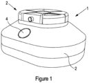
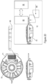
- FIG. 1 illustrates an exemplary SNP genotyping system 1 comprising a base unit or instrument 2 and a test cartridge 3 docked with the base station. Whilst the former component is intended to be reusable many times, the latter component is intended to be single use and disposable.
- the test cartridge is configured to be clipped into the base unit as will be described further below. For the purposes of illustration only, a button 4 is shown incorporated into the base unit 2. With the test cartridge clipped into the base unit, a user can initiate a test by depressing the button 4.
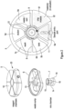
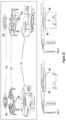
- FIG 2 shows an exploded view of the test cartridge 3 from which is can be seen that the cartridge comprises an upper, multi-chamber unit 5, a lower unit 6 which provides a waste sump and into which the upper housing is clipped, and a rotating chamber 7. From the plan view shown in the Figure, it can be seen that the interior of the upper unit 6 is subdivided into six chambers 5a-f by radially extending walls 8.
- the upper unit provides a central interior space 9 defined by a closed upper surface 10 and a cylindrical wall 11 of the upper unit.
- the space 9 is therefore generally cylindrical, being open at its lower end.
- Each of the chambers 5a-f is in liquid communication with the interior space 9 via an associated radially extending hole in the cylindrical wall 11 (one of these holes is indicated in the Figure by reference numeral 12).
- a circular opening 13 is provided in the lower unit 6 which, in the assembled test cartridge, is aligned with the lower opening into the interior space 9 of the upper unit 5.
- the upper and lower units are constructed of a suitable polymer such as Polypropylene, PTFE or COC.
- the upper unit may be made of a transparent polymer to allow a user to view certain steps in the analysis process.
- the rotating chamber 7 comprises a generally cylindrical member 14 defining an interior (flow through) space closed by an upper wall 15. This is best seen in Figure 3 and in the subsequent Figures. Whilst the upper wall 15 closes the space completely, a circular opening 16 is provided in the base of the cylindrical member 14. A cylindrical wall 17 extends upwardly from the base of the cylindrical member 14, within the interior space. This separates the interior space into a cylindrical space within the cylindrical wall 17, an annular space surrounding the cylindrical wall 17, and a cylindrical space between the top of the cylindrical wall 17 and the upper wall 15 of the cylindrical member 14. An inwardly protruding lip 18 surrounds the upper circumference of the cylindrical wall 17. A bevelled gear "wheel” 19 is formed around the lower, outer periphery of the rotating chamber 7 such that the teeth of the gear wheel face in a generally upward and outward direction.
- a plunger head 20 of rubber (or a material having similar properties) is installed within the rotating chamber so as to be movable up and down within the space defined by the cylindrical wall 17.
- the plunger head 20 forms a substantially airtight and water tight seal within the cylindrical wall 17.
- the plunger head 20 is provided at its lower end with a capture feature 21.
- a pellet of silica fibres/particles (“frit") 64 is pressed into the rotating chamber such that liquid entering the chamber will contact the frit.
- the frit is shown pressed into an opening into the rotating chamber so that, when the opening is aligned with an opening into one of the chambers of the upper unit, liquid is caused to flow through the frit.
- the silica material provides a large area surface for selectively binding DNA via chaotropic-salt-induced adsorption at high salt concentrations, and to avoid the adsorption of proteins, lipids, carbohydrates, and RNA.
- the role of the elution agent (see below) is therefore to decrease the salt concentration and release the bound DNA.
- silica frit to bind DNA is described in "Driving Forces for DNA Absorption to Silica Perchlorate Solutions", Kathryn A. Melzak et al, Journal of Colloidal and Interface Science, 181, 635-644 (1996 ).
- the DNA can be captured on silica-coated magnetic particles, and prevented from leaving the rotating chamber by collecting on a side wall under the application of a magnetic field.
- An example system using magnetic particles and magnetic fields to bind DNA is ChargeSwitch, available from Thermo Fisher, Waltham MA, USA.
- the rotating chamber 7 extends through the opening in the lower unit into the interior central space 9 of the upper unit, forming an interference fit with the cylindrical wall 11 of the upper unit.
- the fit is such that the rotating unit is able to rotate within the upper and lower units.
- the six chambers 5a-f of the upper unit 5 are configured to participate in various stages of a sample analysis procedure.
- the test cartridge is suitable for performing Single Nucleotide Polymorphism (SNP) genotyping on a sample of genetic material obtained from a person or animal.
- SNP genotyping involves detecting which of a number of genetic variations is present at each of one or more SNPs of a person or animal's genome. These SNP variations can provide markers to a condition or trait of the person or animal whose genome is being analysed.
- the chambers 5a-f are configured as follows:
- the analysis chamber is actually formed as a separate, self-contained component 22 which is plugged into an open segment 23 of the upper unit 5.
- This configuration may provide increased flexibility as the upper unit 5 can receive different chip modules depending upon the test to be performed. Also, as the chip modules may have a shorter shelf-life than the assembled upper unit, the latter may be stockpiled in larger quantities with the chip modules being plugged in close to the intended time of use. Of course, the chip module may be formed integrally with the rest of the upper unit 5.
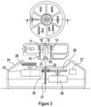
- FIG. 3 shows a cross-section taken vertically through the base unit 2.
- the base unit comprises an outer housing 24 defining a substantially closed interior space.
- the upper surface of the housing 24 and the lower surface of the lower unit 6 have complimentary features to allow for full insertion of the test cartridge 3 into the base unit 2 in only a single rotational orientation.
- the illustrated components include a first rotary motor 25 connected to a bevelled pinion 26.
- the bevelled pinion 26 is provided with a cut-away section to allow the test cartridge 3 to dock flush with the top surface of the base unit 2.
- a controller 27 of the base unit ensures that the bevelled pinion 26 is rotated to a position in which the cut-away section faces towards the centre of the unit. This is the configuration shown in Figure 3 .
- the base unit 2 can be seen to comprise a second rotary motor 28 connected to a first gear wheel 29.
- the first gear wheel 29 meshes with a second gear wheel 30 which is in threaded engagement with a lead screw 31 passing coaxially through the second gear wheel 30.
- the lead screw 31 is provided with a capture head 32. Rotation of the motor spindle in a first direction results in the lead screw 31 moving up, whilst rotation in the opposite, second direction, will result in the lead screw moving down.
- Both the first and the second motor are controlled by the controller 27 which may be, for example, a digital processor with memory for storing control code (power for all components may be provided by an on-board battery or via a ac/dc power inlet).
- the controller In the state where the test cartridge 3 is docked with the base unit 2, the controller is in electrical or wireless communication with one or more components of the test cartridge, for example, with heaters and with a processor of the chip module 22.
- the controller 27 also provides a means to communicate with some external monitoring/analysis system.
- the controller may be able to communicate wirelessly with a user's smartphone, e.g. using a Bluetooth TM or WiFi TM wireless interface. Alternatively, there may be a wired communication interface such as USB, etc.
- the controller may also be able to receive instructions via the same interface.
- Figure 4 shows the test cartridge 3 engaged with the base unit 2, with the bevelled pinion 26 having been rotated to engage the bevelled gear wheel 19 of the rotating chamber 7.
- a radially extending opening 33 formed in the cylindrical member 14 (of the rotating chamber 7) is aligned with the hole 12 into a waste/vent chamber 5e.
- the second motor 28 is now operated to cause the lead screw 31 to extend upwards.
- the upward motion of the lead screw causes the capture head 26 to contact and move upwards the plunger head 20 within the rotating chamber 7.
- the upwards motion of the plunger head causes air to be expelled from the rotating chamber through the vented static chamber.
- the capture head 32 of the lead screw is pushed into the complimentary capture feature 21 formed in the base of the plunger head.
- This configuration is shown in Figure 5 .
- the base unit can be provided with a heater or heaters to raise the temperature of reagents within chambers. Increasing the temperature can improve the yield of DNA extracted from a sample.
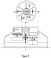
- the bevelled pinion 26 is rotated to turn the rotating chamber 7 so that the opening 33 into the rotating chamber is aligned with the hole 12 leading into the lysis chamber 5b.
- the lead screw 31 is then caused to withdraw downwards by rotating the second motor 28.
- This configuration is shown in Figure 7 from which it can be seen that the downward motion of the lead screw has caused the plunger head 20 at the base of the rotating chamber 7 to be translated downwards by means of the capture head 32.
- the downwards motion of the plunger head 20 generates negative air pressure causing liquid to be drawn from the lysis chamber 5b into the annular space defined within the rotating chamber 7.
- the bevelled pinion 26 is now rotated to turn the rotating chamber 7 so as to align its opening 33 with the opening 12 into the sample chamber 5a.
- the lead screw 31 is then caused to extend upwards by rotating the second motor 28.
- the upward motion of the lead screw causes the plunger head 20 to be translated upwards within the rotating chamber 7.
- the upwards motion of the plunger head generates positive air pressure causing lysis liquid to be expelled from the rotating chamber 7 into the sample chamber 5a. This is shown in Figure 9 .
- workflows for sample processing can be built by sequentially combining rotations of the rotating chamber and movements of the plunger to transfer reagents from the rotating chamber 7 to the static chambers 5a-f and vice versa, and to transfer reagents between static chambers via the rotating chamber.
- Figure 10 illustrates the use of a buccal swab 34 to introduce a sample into the test cartridge.
- the collection end 35 of the swab is pushed into an access port 37 provided in the outer wall of the sample chamber 5a. Once the collection end of the swab is fully inserted, the user snaps off the handle 36.
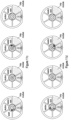
- FIG. 11 Illustrated in Figure 11 is a workflow for sample processing is as follows, assuming the use of a buccal swab to collect a sample of genetic material:
- the analysis chamber is provided by a chip module which relies upon electrochemical detection mechanisms, e.g. ISFET-based sensors.
- An analysis chamber of the test cartridge may make use of electrochemical-based detection techniques (such as those available from Genmark Dx, Carlsbad CA, USA), or may make use of thermal stability of matched probe-target versus mismatched probe-target as a detection technique.
- the analysis chamber makes use of fluorescence-based detection techniques.
- the process may use intercalating dye, e.g. SYBR Green or as described in the Internet publication: http://www.bio-rad.com/webroot/web/pdf/Isr/literature/Bulletin_10014647.pdf.
- An alternative approach involves the use of a probe-based approach, e.g. https://www.thermofisher.com/uk/en/home/life-science/pcr/real-time-pcr/real-time-pcr-assays/snp-genotyping-taqman-assays.html.
- the exemplary SNP genotyping system 1 described above employs two openings into the rotating chamber 7, one unimpeded and the other impeded by the silica frit 64. However, more or fewer openings may be employed. For example, an example may employ only a single opening into the rotating chamber, that opening being impeded by a silica frit.
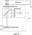
- FIG. 12 illustrates an example system in which a base unit 50 is provided with a smartphone docking station 51. A user's smartphone 52 is docked with the base station via the docking station. A test cartridge 53 is shown inserted into a cartridge reception port 54 of the base unit.
- a base unit 50 is provided with a smartphone docking station 51.
- a user's smartphone 52 is docked with the base station via the docking station.
- a test cartridge 53 is shown inserted into a cartridge reception port 54 of the base unit.
- test cartridge and base unit of this second example system have similar functionality to the respective components of the first example, although modification is required in order to allow visual access to the analysis chamber.
- modification is required in order to allow visual access to the analysis chamber.
- skilled person will be readily able to realise changes in the style and form of the system without changing the fundamental operating principles.
- the docking station 51 comprises optics or at least a line of sight to optically couple a camera on the underside of the smartphone 52 with the analysis module at least when the test cartridge has been rotated to an optical detection position.
- the docking station and optics may provide for use with a number of different smartphones having different shapes and sizes and camera positions, e.g. using adjustable optics and or adaptors of differing configurations.
- the docking station may include an electromechanical interface to enable two-way communication between the base unit and the smartphone: for example, a Lightning TM male connector port may be used to interface with an iPhone TM .
- the smartphone and the base unit may communicate wirelessly.
- the smartphone By making use of an analysis control app (software application) installed on the smartphone, the smartphone may be used to control the operation of the base unit and therefore the analysis process. Imaging data captured by the smartphones camera may be analysed within the smartphone and or by making use of a service in the "cloud”.
- an analysis control app software application
- a personalised genetic-based service which aims to provide advice and recommendations to users across a range of different categories.
- These categories might include nutrition (possibly divided into more refined sub-categories such as weight loss, allergies, intolerances, etc), exercise, sleep, etc.
- nutrition possibly divided into more refined sub-categories such as weight loss, allergies, intolerances, etc
- exercise sleep, etc.
- SNPs are identified which can be used to classify user traits.
- SNPs are identified which can be used to classify user traits.
- Analysis chambers 5f such as a chip module, are configured for each category of the service.
- an analysis chamber used for the nutrition category is configured to test for the SNPs relevant to nutrition.
- the other chambers of the test cartridge may be configured for this specific analysis chamber if it is not generic to all analysis chamber types.
- test cartridges may be purchased via a web shop and delivered to the user's home, or purchased in a store and brought home for use.
- the user inserts the purchased test cartridge into the base unit and docks his or her smartphone.
- the user then opens the relevant app on the smartphone (assuming that it has been pre-installed).
- the app detects automatically that the smartphone is docked.
- Some form of authentication may be performed on the test cartridge.
- the camera may be used to read a barcode or other machine readable code present on the test cartridge.
- Authentication can be performed using some algorithm available to the app and/or by communicating with the cloud. Alternatively, authentication may rely on communication between the test cartridge and the base station, optionally involving the smartphone.
- the user can initiate the test by tapping on a "button" presented on the smartphone's touchscreen.
- the app may be configured to provide any suitable form of graphical user interface, menu selection, etc.
- the smartphone Via the docking station, the smartphone communicates with the base unit, causing it to operate the first and second motors, heaters, etc, in order to carry out the various steps of the SNP genotyping procedure.
- a signal is sent to the smartphone to cause the smartphone to operate its camera. Although in some cases only a single image may be captured upon completion of the test, by capturing multiple images throughout the procedure specificity to the test result may be enhanced.
- the app is provided with algorithms to process and analyse the captured image(s). Again, this may make use of processing within the cloud. If the cloud is used, then data exchanged between it and the smartphone is secured using encryption. Furthermore, data may be anonymised to prevent any direct association between the data and the user.
- the result of the analysis may be a set of user-specific traits. These traits may in turn be mapped to a set of recommendations. In the case of nutrition, assuming a sub-category of weight loss, the set of recommendations may comprise a database of food products each mapped to a recommendation. The database is loaded into the smartphone app, e.g. by downloading it from the cloud.
- the database of food products may include, for each product, a barcode matching the barcode used on the product packaging.
- Databases of product barcodes are widely available, e.g. from supermarkets etc.
- the app on the smartphone is enabled with a barcode reader which makes use of the built-in camera.
- the user can use the smartphone/app to scan a product barcode before or after purchase.
- the app will recognise the product and indicate the personalised product recommendation.
- the user may be advised, via the smartphone GUI, that the product is recommended for weight loss or is inadvisable.
- the app may even recommend a similar, alternative product that is preferred.
- the app may be configured to encourage or "nudge" the user to change their purchasing/consumption behaviour, rather than trying to enforce a change. This might include for example the use of rewards, financial or otherwise.
- the smartphone may share data with a wearable device such as a fitness (wrist) band, with the wearable device having its own barcode reader.
- Product barcodes may be read by the wearable device, data exchanged between the smartphone and the wearable device, and product recommendations provided either by the smartphone or the wearable device.
- the communication between the smartphone and the wearable device is via a secure link under the user's control, e.g. via a Bluetooth TM interface, the user retains control of his or her personal data at all times.
- Examples of this disclosure overcome clear technical problems arising with previously known systems and methods, namely the need to send personal and sensitive genetic data outside of the user device (smartphone).
- FIG. 13 illustrates schematically a system configured to operate in accordance with this approach.
- a user smartphone 55 is docked with an instrument 56 via docking compartment 57 of the instrument.
- the docking compartment comprises optics to direct the smartphone's camera 58 onto a result area of a test cartridge held in the instrument.
- the test instrument comprises a controller 59 which communicates with the smartphone and controls operations performed within the instrument.
- the instrument also comprises a memory 60 which may store both code for execution by the processor and data, e.g. parameter data and result data.
- the smartphone comprises a specially configured processor, e.g. configured using code stored in a memory 61, which detects docking of the smartphone and operates the camera to capture a result image.
- the processor may also determine a cartridge type, i.e.
- the processor further analyses a captured image to map the results to a user characteristic or trait. For example, in the case of an allergy type cartridge/test, the processor may determine from the result image that the user has a nut allergy.
- the smartphone is operated by a microprocessor 63 and maintains a product database 62, e.g. listing all products stocked by a particular supermarket.
- the database includes, for each product, an associated barcode.
- the database is populated with determined product recommendations.
- entries for all products containing nuts may be tagged with a recommendation "do not purchase”.
- the smartphone is removed from the dock and a product barcode subsequently scanned, the product database within the smartphone may be inspected to determine the corresponding product recommendation.
- the recommendation can then be presented to the user, e.g. via the display, and audible signal, vibration alert, etc.
- the smartphone may be configured to communicate with one or more network servers via, for example, the Internet, in order to delegate part of the processing operation to the server or servers, and/or to obtain current data.
- Examples of alternative methods for detecting biomarkers and suitable for use with embodiments of the invention include: Conductivity/pH, Electrochemical, Refractive index, End point, Thermal stability. Examples of other amplification methods include Isothermal and Thermal cycling. Examples of other readouts (other than SNP) include RNA profile, DNA methylation.
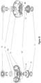
- Figure 14 illustrates schematically a system for use with a user's smartphone to detect SNPs in a sample of genetic material.
- the system again comprises a base unit 65 and in which are located a number of components including optics 66, a PCB 67, a rotational stepper motor 68, and a syringe 69.
- the optics 66 can be slid to the right (as viewed in the Figure) to allow a test cartridge 70 (only part of which is shown in the Figure) to be inserted into the base unit from above. Once inserted, the optics are slid to the left so that they sit above the analysis chamber 71 of the test cartridge.
- the system is then initialised, causing a PCR stepper driver to press a Peltier module 72 (used to perform PCR) upwards against an under surface of the analysis chamber 71.
- a PCR stepper driver to press a Peltier module 72 (used to perform PCR) upwards against an under surface of the analysis chamber 71.
- the analysis chamber is squeezed between the Peltier module and the optics, forcing liquid into the wells of the analysis chamber (further details are presented below).
- the syringe 69 within the base unit 65 is configured to apply positive or negative pressure to the flow through chamber within the test cartridge via a series of communicating channels. This is described further below.
- Figure 14 illustrates a smartphone 73 docked with the base unit 65 such that a camera of the smartphone sits directly above the optics 66.
- the smartphone can be used to capture an image result produced within the analysis chamber 71.
- the smartphone may communicate wirelessly, or via a dock or cable, with a controller of the base unit (e.g. located on the PCB 67) in order to control the test procedure.
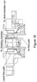
- Figure 15 shows a cross-section through the test cartridge 70 according to the modified system of Figure 14 .
- Figure 16 is an exploded view of the test cartridge from above (left) and below (right).
- a rotating chamber 74 sits generally within a multi-chamber unit 75.
- the rotating chamber comprises a cylindrical member 82 defining the flow chamber.
- the multi-chamber unit 75 cannot rotate, whilst the rotating chamber 74 is able to rotate under the control of the rotational stepper motor 68.
- the rotating chamber 74 and multi-chamber unit 75 are secured between an upper wall component 76 and a locking nut 77.
- a spring 78 urges the frustoconical surface of the rotating chamber 74 against the opposed inner surface of the multi-chamber unit 75.
- a main opening 79 (containing a silica frit) is provided in the frustoconical surface of the rotating chamber 48, and communicates with the flow through chamber thereof.
- a number of apertures 96 are formed around the inner surface of the multi-chamber unit, aligned with respective chambers. Each of these apertures is provided with an elastomeric O-ring 80 which provides sealing against the frustoconical surface of the rotating chamber.
- the apertures are configured such that the opening 79 in the frustoconical surface can be selectively aligned with apertures in the multi-chamber unit, whilst the O-ring seals prevent leakage from the unaligned apertures of the multi-chamber unit.
- the analysis chamber is not present. Rather, the analysis chamber is plugged into the vacant slot immediately prior to use.
- test cartridge 70 Whilst the construction of the test cartridge 70 differs from that described with reference to Figure 2 , much of the functionality is the same.
- this modified system uses a syringe (pump) in the base unit to pneumatically move the liquids.
- a syringe pump
- Figure 17 illustrates liquid 81 present within one of the chambers of the multi-chamber unit 75, with the aperture of this chamber being aligned with one of the apertures provided in the rotating chamber 74.
- Air is drawn by the syringe in the base unit through a path indicated by the series of arrows. This path comprises a rotatable coupling between the base unit and the flow through chamber within the cylindrical member 82.
- the rotating chamber 74 When the rotating chamber 74 is filled with liquid, there may be a risk of liquid splashing upwards and then dropping down into the air flow paths connecting to the base unit.
- the rotating chamber may be provided with a two way valve 83, sitting towards the upper end of the cylindrical member 82. This valve allows air to pass under pressure in both directions, i.e. into and out of the chamber, but prevents splashes from moving to the top of the chamber.
- the valve may be, for example, a "duck-bill umbrella" valve.
- Figure 20 illustrates at A a top plan view in cross-section of the test cartridge 70 with the analysis chamber 71 installed.
- the analysis chamber 71 comprises an array of wells 84 within which the PCR reaction occurs and within which the visible results are produced.
- the base 85 of the wells is formed by a material that allows air to pass through but which is impermeable to liquid.
- a linear actuator 86 is engaged with the Peltier module 72 in order to bias the bottom of the analysis chamber upwards, pressing the top of the analysis chamber against the bottom of the optics. This exerts a pressure on the liquid above the wells, forcing it into the wells in order to achieve satisfactory fill levels. This clamping pressure also ensures good thermal contact between the base of the analysis chamber 71 and the Peltier module 72.
- FIG. 21 This mechanism for applying pressure above the wells to fill the wells is further illustrated in Figure 21 .
- a liquid and air impermeable membrane (a) above the wells and a liquid impermeable and air permeable (hydrophobic) layer (d) below the wells an air and liquid permeable layer (c) is fixed directly on top of the wells beneath the layer (a) and is sealed to the surface between the wells.
- This layer (c) is two-fold. Firstly, it provides resistance to well filling so that the wells do not fill while the volume between layers (a) and (c) is being filled. This minimises the risk of material being carried between wells during filling.
- the layer (c) can provide some resistance to "cross-talk" between wells.
- Layer (c) may be relatively hydrophobic with a mesh size sufficient to prevent the passage of liquid unless the liquid pressure exceeds some required level. Cross-talk is also reduced due to the clamping of the layer (a) against the surface by the optics. In some cases layer (c) may be omitted.
- one or more biomarkers e.g. primers/probes
- the biomarker(s) may be spotted or otherwise fixed to the upper surface the hydrophobic layer (d).
- Figure 22 illustrates an alternative mechanism for filling the wells, where filling is from the bottom of the wells.
- a layer (c) which is permeable to air and liquid is provided both above and below the wells, sealed between the wells.
- a small region of the layer (a) is provided as layer (d) being permeable to air but impermeable to liquid.
- a further layer of material that is permeable to air but impermeable to liquid (hydrophobic) may be sandwiched between the lower layer (c) and the base of the wells. In such an arrangement the layer (c) will absorb liquid and bring it into contact with the hydrophobic layer. Under pressure, liquid is then forced through the hydrophobic membrane into the well.
- Figure 23 illustrates one possible mechanism for achieving this (a modification to the analysis chamber of Figures 15 to 20 and 24 ) and relies upon the provision of a foil or other breakable component on top of each of the chambers.
- An intermediate component 87 is located above the multi-chamber unit 75 and has a small degree of movement in an axial direction relative to multi-chamber unit. However the component 87 and the multi-chamber unit 75 cannot rotate relative to one another.
- the upper wall component 76 is modified to include one or more cams 88 which are able to exert a downward force onto the intermediate component 87.
- the cams 88 act to press the component 87 down onto the multi-chamber unit 75.
- This causes a set of piercing arms 89, aligned with respective chambers, to pierce the foil covers on the chambers thereby venting the chambers to the surrounding environment. Whilst the piercing arms 89 may be raised subsequently as the rotating chamber is further rotated, the venting paths remain open.
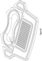
- FIG 24 illustrates in more detail the analysis chamber 71.
- the chamber comprises an array of wells 84 as previously described and a "bone" shaped trough 90 providing a pair of end lobes joined by a central channel.
- An inlet opening 91 in the base of one of the lobes communicates with the main opening 92 into the analysis chamber. That main opening is the opening that in use is brought into communication with the opening 79 of the rotating chamber via a channel of the multichamber unit.
- the opening 92 communicates with this channel.
- the channel is identified in Figure 15 by reference numeral 97.
- An outlet opening 93 in the other of the lobes communicates with an well injection opening 94 adjacent to the wells.
- the Figure shows a lyophilized (or freeze dried) particle 95 present in the inlet opening 91.
- This particle 95 comprises so-called "mastermix” that is dissolved into liquid as liquid flows from the main chamber opening 92 to the trough 90.
- mastermix may be provided as a dried component elsewhere in the analysis chamber or could be provided in liquid form in another chamber of the multichamber unit 75.
- the analysis chamber 71 is covered by a transparent, plastic sheet that is welded around the periphery of the chamber 71.
- the plastic sheet is further welded to the top of the chamber 71 to provide pockets above the trough 90 and the array of wells 84 that are isolated from one another. [Welding locations are shown in red in Figure 25 .] This ensures that liquid can only pass from one pocket to the other via the openings 91, 93.
- the base of the trough 90 is slightly inclined, such that when the top of the chamber 71 is level, as is the case in use, the base of the outlet lobe of the trough 90 is lower than the base of the inlet end of the trough.
- a centrally located waist of the trough 90 also provides a restriction to the flow of liquid from the inlet side to the outlet side, and is further raised slightly with respect to the bottom of both sides. This arrangement helps to avoid the formation of bubbles in the liquid as the trough is filled and improves mixing. It will be appreciated that, in use, as the Peltier module 72 is pushed upwards ( Figure 20 ), the plastic sheet on top of the chamber 71 is pressed against the bottom of the optics 66, forcing the sheet against the surface of the chamber and creating a pressure to cause filling of the wells.
- the wells are defined by inclined walls so that the area of the base of the wells is greater that the area of the top of the wells. Whilst this structure facilitates injection moulding of the chamber, it has also been found to be advantageous in reducing or avoiding the accumulation of materials on the sidewalls.
- Figure 26 shows in red where a further, air and liquid impermeable membrane may be welded to the base of the cartridge. It is also noted that a pair of voids are provided on either side of the bottom of the well array, i.e. under the further sheet. As already described, the base of the wells are covered with a first air-permeable (hydrophobic) membrane while the entire well plus void areas are covered by the further membrane which is elastomeric.
- air from the wells exits through the first hydrophobic membrane and fills the space enclosed by the second, further membrane. This air acts as an insulating medium allowing more even heat distribution across the well array during thermal cycling.
- the clamping of the analysis chamber between the Peltier and the optics acts as a valve to shut off the air path between the base of the wells and the air voids.
- the position of the weld line in Figure 26 is important as it allows a good seal between the Peltier unit and the base of the wells (if there was a weld in that region, the seal would be poor).
- the optics module seals across the upper surface of the well area, preventing liquid communication between the wells.
- the Peltier module seals across the base of the wells, preventing air communication between the wells and voids. In both cases we want to avoid valving in a region with a weld line.
- each well may be surrounded at its upper opening by an upwardly projecting lip or rim.
Landscapes
- Chemical & Material Sciences (AREA)
- Health & Medical Sciences (AREA)
- Life Sciences & Earth Sciences (AREA)
- General Health & Medical Sciences (AREA)
- Engineering & Computer Science (AREA)
- Analytical Chemistry (AREA)
- Organic Chemistry (AREA)
- Physics & Mathematics (AREA)
- Chemical Kinetics & Catalysis (AREA)
- Biochemistry (AREA)
- Molecular Biology (AREA)
- Proteomics, Peptides & Aminoacids (AREA)
- Wood Science & Technology (AREA)
- Zoology (AREA)
- Immunology (AREA)
- Clinical Laboratory Science (AREA)
- General Physics & Mathematics (AREA)
- Pathology (AREA)
- Hematology (AREA)
- Bioinformatics & Cheminformatics (AREA)
- Medical Informatics (AREA)
- Public Health (AREA)
- Microbiology (AREA)
- Biotechnology (AREA)
- Biophysics (AREA)
- General Engineering & Computer Science (AREA)
- Genetics & Genomics (AREA)
- Biomedical Technology (AREA)
- Epidemiology (AREA)
- Primary Health Care (AREA)
- Theoretical Computer Science (AREA)
- Business, Economics & Management (AREA)
- Dispersion Chemistry (AREA)
- Spectroscopy & Molecular Physics (AREA)
- Computing Systems (AREA)
- Electrochemistry (AREA)
- Microelectronics & Electronic Packaging (AREA)
- Finance (AREA)
- Marketing (AREA)
- General Business, Economics & Management (AREA)
Claims (10)
- System (1) zur Vorbereitung und Durchführung einer PCR an einer Probe aus biologischem Material, das DNA oder RNA enthält, wobei das System Folgendes umfasst:
eine Testpatrone (70), welche Folgendes aufweist:ein erstes Gehäuse, welches eine Durchflusskammer (74) definiert,ein zweites Gehäuse (75), das einen zentralen Raum definiert, in dem das erste Gehäuse (74) mindestens teilweise befindlich ist, wobei das erste Gehäuse in Bezug auf das zweite Gehäuse drehbar ist, und das zweite Gehäuse eine Vielzahl von in Umfangsrichtung beabstandeten Kammern definiert, wobei eine der Kammern einen Einlass zur Aufnahme einer Probe aufweist, wobei mindestens eine der Kammern ein flüssiges Reagenz enthält, und mindestens eine der Kammern eine Analysekammer (71) ist, die in das zweite Gehäuse eingesteckt oder einstückig mit dem zweiten Gehäuse gebildet ist, wobei die Analysekammer zur Durchführung der PCR bestimmt ist, wobei die Kammern des zweiten Gehäuses jeweils eine Öffnung in den zentralen Raum aufweisen,wobei das erste Gehäuse eine oder mehrere Öffnungen (79) in den zentralen Raum dergestalt aufweist, dass die oder jede Öffnung selektiv mit einer der Öffnungen in die Kammern des zweiten Gehäuses durch relative Drehung des ersten Gehäuses und des zweiten Gehäuses ausgefluchtet werden kann,eine Basiseinheit, welche Folgendes aufweist:ein Gehäuse, das Merkmale zum Andocken der Testpatrone (70) an die Basiseinheit definiert oder mit diesen dergestalt verbunden ist, dass das zweite Gehäuse (75) sich in Bezug auf die Basiseinheit nicht drehen kann, während das erste Gehäuse sich in Bezug auf die Basiseinheit drehen kann,ein Peltier-Modul (72), derart angeordnet, dass es sich unterhalb der Analysekammer befindet, um die Analysekammer zu erwärmen und zu kühlen,einen ersten Treiber zum Eingreifen in das erste Gehäuse, um eine Drehung des ersten Gehäuses innerhalb des zweiten Gehäuses zu bewirken,einen zweiten Treiber zur positiven und negativen Druckbeaufschlagung der Durchflusskammer des ersten Gehäuses (74),eine Steuerung zum Betreiben des ersten und des zweiten Treibers, um eine Verdrängung von Flüssigkeiten zwischen den Kammern in einer gewünschten Reihenfolge zu bewirken, was zur Abgabe einer vorbereiteten Probe an die Analysekammer führt und dadurch die Bereitstellung eines Analyseergebnisses durch die Analysekammer erleichtert, undein Optikmodul (66), das an eine Stelle oberhalb der Analysekammer verschiebbar ist, um in der Analysekammer erzeugte, visuell erfassbare Analyseergebnisse von oben abbilden zu können,wobei die Analysekammer (71) Folgendes umfasst:
ein Basiselement, das Folgendes definiert:einen Einlass in Flüssigkeitsverbindung mit der Öffnung der Analysekammer zur Aufnahme einer Flüssigkeit, die die Probe aus biologischem Material oder eine aus der Probe aus biologischem Material aus der Durchflusskammer abgeleitete Komponente enthält, undeine Anordnung von Vertiefungen (84), in denen eine PCR durchgeführt werden kann, undeine flexible transparente, luft- und flüssigkeitsundurchlässige Kunststofffolie (a), die an einer Oberseite des Basiselements befestigt ist, um einen Raum zu definieren, der an die Anordnung von Vertiefungen angrenzt und in den sich die Vertiefungen öffnen, wobei der Raum in Flüssigkeitsverbindung mit dem Einlass steht; undwobei die Analysekammer so konfiguriert ist, dass sie visuell erfassbare Analyseergebnisse liefert, die von oben über der Testpatrone durch die Folie sichtbar sind, wobei die sichtbaren Ergebnisse durch einen oder mehrere Biomarker in jeder Vertiefung erzeugt werden, wobei die Basen (85) der Vertiefungen durch eine Schicht aus Material (d) bereitgestellt werden, welche luftdurchlässig, aber flüssigkeitsundurchlässig ist, undwobei die Basiseinheit ferner ein mit dem Peltier-Modul in Eingriff stehendes Linearbetätigungsglied (86) umfasst, um den Boden der Analysekammer (71) nach oben vorzuspannen, wodurch die Oberseite der Analysekammer (71) gegen den Boden der Optik gedrückt wird, welche sich nicht in der vertikalen Richtung bewegen kann, wodurch ein Druck auf die Flüssigkeit über den Vertiefungen (84) ausgeübt wird, wodurch die Flüssigkeit in die Vertiefungen gezwängt wird, um zufriedenstellende Füllstände zu erreichen. - System nach Anspruch 1, wobei das zweite Gehäuse ferner mindestens eine leere Kammer zum Entlüften oder Aufnehmen von Abfallflüssigkeit definiert.
- System nach Anspruch 1 oder 2, wobei der Einlass zur Aufnahme einer Probe konfiguriert ist, um einen Probenkopf eines Tupfers (36) aufzunehmen.
- System nach einem der vorhergehenden Ansprüche, wobei das System zur Durchführung von Einzelnukleotidpolymorphismus-Genotypisierung konfiguriert ist, und die Kammern der Testpatrone (70) mindestens eine Kammer umfassen, die einen Lysepuffer enthält, eine Kammer, die ein Waschflüssigkeitsreagenz enthält, und eine Kammer, die ein Elutionsreagenz enthält.
- System nach Anspruch 4, wobei die Analysekammer (71) zur Durchführung von DNA-Amplifikation konfiguriert ist und eine Schnittstelle zur Anzeige der Amplifikation aufweist.
- System nach einem der vorhergehenden Ansprüche, und Merkmale zur Erleichterung des Andockens eines Smartphones (73) an das System dergestalt, dass ein Analyseergebnis der Analysekammer durch eine Kamera des Smartphones abgebildet werden kann, umfassend.
- System nach einem der vorhergehenden Ansprüche, wobei das erste Gehäuse (74) eine poröse Membran (64) innerhalb oder in Flüssigkeitsverbindung mit der Durchflusskammer (74) umfasst, wobei die poröse Membran zum Zurückhalten von DNA-Material konfiguriert ist.
- System nach Anspruch 7, wobei die poröse Membran eine Siliziumdioxidfritte (64) ist.
- System nach Anspruch 7 oder 8, wobei das erste Gehäuse (74) zwei oder mehrere der Öffnungen (79) in den zentralen Raum umfasst, wobei mindestens eine der Öffnungen unbehindert ist und eine andere der Öffnungen durch die poröse Membran (64) behindert wird.
- System nach Anspruch 9, dazu konfiguriert, dass, wenn eine der behinderten und der unbehinderten Öffnungen mit einer der Öffnungen in die Kammern des zweiten Gehäuses ausgefluchtet ist, die andere der behinderten und der unbehinderten Öffnungen nicht derart ausgefluchtet ist.
Priority Applications (1)
| Application Number | Priority Date | Filing Date | Title |
|---|---|---|---|
| EP21158692.0A EP3862089A1 (de) | 2016-09-23 | 2017-09-25 | Testkartusche zur analyse einer biologischen probe |
Applications Claiming Priority (2)
| Application Number | Priority Date | Filing Date | Title |
|---|---|---|---|
| GB1616174.7A GB2554377A (en) | 2016-09-23 | 2016-09-23 | Method and apparatus for analysing a biological sample |
| PCT/GB2017/052855 WO2018055407A1 (en) | 2016-09-23 | 2017-09-25 | Method and apparatus for analysing a biological sample |
Related Child Applications (2)
| Application Number | Title | Priority Date | Filing Date |
|---|---|---|---|
| EP21158692.0A Division-Into EP3862089A1 (de) | 2016-09-23 | 2017-09-25 | Testkartusche zur analyse einer biologischen probe |
| EP21158692.0A Division EP3862089A1 (de) | 2016-09-23 | 2017-09-25 | Testkartusche zur analyse einer biologischen probe |
Publications (3)
| Publication Number | Publication Date |
|---|---|
| EP3515599A1 EP3515599A1 (de) | 2019-07-31 |
| EP3515599C0 EP3515599C0 (de) | 2024-07-24 |
| EP3515599B1 true EP3515599B1 (de) | 2024-07-24 |
Family
ID=57539844
Family Applications (2)
| Application Number | Title | Priority Date | Filing Date |
|---|---|---|---|
| EP17777358.7A Active EP3515599B1 (de) | 2016-09-23 | 2017-09-25 | System zur analyse einer biologischen probe |
| EP21158692.0A Pending EP3862089A1 (de) | 2016-09-23 | 2017-09-25 | Testkartusche zur analyse einer biologischen probe |
Family Applications After (1)
| Application Number | Title | Priority Date | Filing Date |
|---|---|---|---|
| EP21158692.0A Pending EP3862089A1 (de) | 2016-09-23 | 2017-09-25 | Testkartusche zur analyse einer biologischen probe |
Country Status (8)
| Country | Link |
|---|---|
| US (1) | US10093965B2 (de) |
| EP (2) | EP3515599B1 (de) |
| JP (2) | JP6944999B2 (de) |
| KR (1) | KR102375927B1 (de) |
| CN (3) | CN109803759B (de) |
| AU (1) | AU2017332842B2 (de) |
| GB (1) | GB2554377A (de) |
| WO (1) | WO2018055407A1 (de) |
Families Citing this family (43)
| Publication number | Priority date | Publication date | Assignee | Title |
|---|---|---|---|---|
| EP3594360B1 (de) | 2014-04-24 | 2021-06-23 | Lucira Health, Inc. | Kolorimetrische detektion von nukleinsäureamplifikation |
| CA3015368A1 (en) | 2016-03-14 | 2017-09-21 | Diassess Inc. | Systems and methods for performing biological assays |
| CA3015378C (en) | 2016-03-14 | 2023-09-26 | Diassess Inc. | Selectively vented biological assay devices and associated methods |
| JP6891191B2 (ja) | 2016-03-14 | 2021-06-18 | ルシラ ヘルス インコーポレイテッド | 光学的性質を改変するための装置および方法 |
| GB2554377A (en) * | 2016-09-23 | 2018-04-04 | Dnanudge Ltd | Method and apparatus for analysing a biological sample |
| US11080848B2 (en) | 2017-04-06 | 2021-08-03 | Lucira Health, Inc. | Image-based disease diagnostics using a mobile device |
| WO2019055135A1 (en) | 2017-09-14 | 2019-03-21 | Diassess Inc. | MULTIPLEXED BIOLOGICAL ASSAY DEVICE WITH ELECTRONIC READING |
| US10549275B2 (en) | 2017-09-14 | 2020-02-04 | Lucira Health, Inc. | Multiplexed biological assay device with electronic readout |
| KR102065650B1 (ko) * | 2017-12-28 | 2020-02-11 | 에스디 바이오센서 주식회사 | 카트리지를 이용한 핵산 추출 방법 |
| US10841662B2 (en) | 2018-07-27 | 2020-11-17 | Telefonaktiebolaget Lm Ericsson (Publ) | System and method for inserting advertisement content in 360° immersive video |
| WO2020027544A1 (ko) * | 2018-08-02 | 2020-02-06 | 사회복지법인 삼성생명공익재단 | 현장용 유전체 추출 장치 및 이를 이용한 유전체 추출 방법 |
| CN109884330B (zh) * | 2019-04-11 | 2024-03-26 | 石家庄禾柏生物技术股份有限公司 | 向碟片轴心方向输送液体的装置 |
| CN109946469B (zh) * | 2019-04-11 | 2024-03-26 | 石家庄禾柏生物技术股份有限公司 | 一种向碟片中心方向输送液体的装置 |
| CN109941949B (zh) * | 2019-04-11 | 2024-04-30 | 石家庄禾柏生物技术股份有限公司 | 向碟片中心方向输送液体的装置 |
| US11501356B2 (en) * | 2019-07-31 | 2022-11-15 | L'oreal | Systems and methods for generating personalized skincare formulations based on biomarker analysis |
| FR3102847B1 (fr) * | 2019-11-06 | 2021-10-15 | Ilsa | Dispositifs de cytocentrifugation |
| GB201918900D0 (en) * | 2019-12-19 | 2020-02-05 | Vidya Holdings Ltd | Improvements in or relating to assay timing |
| BR112022012927A2 (pt) * | 2019-12-30 | 2022-09-06 | Abbott Diagnostics Scarborough Inc | Dispositivo de preparo de amostra e métodos para uso deste |
| CN113391077B (zh) * | 2020-03-11 | 2025-09-02 | 杭州准芯生物技术有限公司 | 液体检测系统和方法 |
| CN111474152B (zh) * | 2020-04-18 | 2025-03-11 | 杭州准芯生物技术有限公司 | 液体检测系统 |
| USD953561S1 (en) | 2020-05-05 | 2022-05-31 | Lucira Health, Inc. | Diagnostic device with LED display |
| USD962470S1 (en) | 2020-06-03 | 2022-08-30 | Lucira Health, Inc. | Assay device with LCD display |
| JP7252925B2 (ja) * | 2020-06-25 | 2023-04-05 | オートノマス メディカル デバイシズ,インコーポレイテッド | ポイントオブケア(poc)で病原体及び抗体アレイを検出するクラウドベースの自動検出システム及び方法 |
| WO2022051694A1 (en) * | 2020-09-04 | 2022-03-10 | Lucira Health, Inc. | Streamlined assay preparation |
| US11384403B2 (en) | 2020-11-10 | 2022-07-12 | Dnanudge Limited | Use of pooled samples to optimise the efficiency and utility of a rapid, lab-free point-of-care test |
| GB2600774A (en) * | 2020-11-10 | 2022-05-11 | Dnanudge Ltd | The use of pooled samples to optimise the efficiency and utility of a rapid, lab-free point-of-care test |
| CN116457097A (zh) * | 2020-12-01 | 2023-07-18 | 伊鲁米那有限公司 | 井凹组件和相关方法 |
| US20220193659A1 (en) * | 2020-12-17 | 2022-06-23 | Philmedi Co.,Ltd. | All-in-one kit for on-site molecular diagnosis and molecular diagnosis method using same |
| KR102326826B1 (ko) * | 2021-01-14 | 2021-11-16 | (주)얼라인드제네틱스 | 애널라이트 검사 장치 및 이를 이용한 애널라이트 검사 방법 |
| JP2023026238A (ja) * | 2021-08-13 | 2023-02-24 | 株式会社Mirai Genomics | 流体処理カートリッジ並びに核酸の回収及び増幅方法 |
| RU2768005C1 (ru) * | 2021-09-02 | 2022-03-22 | Общество С Ограниченной Ответственностью "Тробио" | Одноразовый картридж для выделения нуклеиновых кислот и их последующей амплификации (варианты) |
| CN114088929B (zh) * | 2021-10-27 | 2024-07-09 | 中铁三局集团有限公司 | 一种混凝土耐久性测试装置 |
| CN114200134B (zh) * | 2021-11-26 | 2023-11-07 | 中国农业大学 | 用于微生物检测的自动化快速检测装置、系统及方法 |
| AU2022426691A1 (en) * | 2021-12-29 | 2024-08-08 | Memorial Hospital For Cancer And Allied Diseases | Vessels, devices, processes, and systems for tracking and managing items with circuitous custody chains |
| US20230278029A1 (en) | 2022-03-01 | 2023-09-07 | Dnanudge Limited | Multiplex cartridge for detection of viral nucleic acids and human or animal snps |
| CN114935555B (zh) * | 2022-06-28 | 2024-09-24 | 中国农业科学院农产品加工研究所 | 面粉吸水率快速无损检测方法 |
| EP4597117A1 (de) * | 2022-09-30 | 2025-08-06 | Kabushiki Kaisha Mirai Genomics | Flüssigkeitsverarbeitungskartusche und verfahren zur rückgewinnung und amplifikation von nukleinsäure |
| KR20240080370A (ko) * | 2022-11-30 | 2024-06-07 | 주식회사 퀀타매트릭스 | 유전자 추출 및 검출용 카트리지 |
| KR102798102B1 (ko) * | 2022-11-30 | 2025-04-22 | 주식회사 퀀타매트릭스 | 유전자 추출 및 검출용 시스템 |
| US12024739B1 (en) | 2023-03-15 | 2024-07-02 | Dnanudge Limited | Method and apparatus for rapid analysis of a biological sample |
| WO2025042200A1 (ko) * | 2023-08-22 | 2025-02-27 | (주)래피젠 | 핵산 추출, 증폭, 및 분석을 위한 진단용 카트리지 |
| CN118454468B (zh) * | 2024-07-15 | 2024-09-06 | 山东招金膜天股份有限公司 | 一种反渗透膜在线检测装置 |
| CN118857895B (zh) * | 2024-09-27 | 2024-12-17 | 东北大学 | 一种矿物固废检测装置 |
Citations (2)
| Publication number | Priority date | Publication date | Assignee | Title |
|---|---|---|---|---|
| EP2198967A2 (de) * | 2008-12-09 | 2010-06-23 | Ngk Insulator, Ltd. | Mit DNA-Anordnung ausgerüstete Kartusche, Analysegerät und Verfahren zur Verwendung der mit der DNA-Anordnung ausgerüsteten Kartusche |
| US20110020179A1 (en) * | 2005-04-26 | 2011-01-27 | Life Technologies Corporation | Systems and Methods for Multiple Analyte Detection |
Family Cites Families (27)
| Publication number | Priority date | Publication date | Assignee | Title |
|---|---|---|---|---|
| US5284753A (en) | 1991-03-20 | 1994-02-08 | Neuro Probe, Inc. | Multiple-site chemotactic test apparatus and method |
| US5922288A (en) * | 1997-05-29 | 1999-07-13 | Herst; C. V. Taylor | Device for isolating a component of a physiological sample |
| US6531095B2 (en) * | 1999-02-11 | 2003-03-11 | Careside, Inc. | Cartridge-based analytical instrument with optical detector |
| US6589778B1 (en) | 1999-12-15 | 2003-07-08 | Amersham Biosciences Ab | Method and apparatus for performing biological reactions on a substrate surface |
| US8048386B2 (en) | 2002-02-25 | 2011-11-01 | Cepheid | Fluid processing and control |
| US7077152B2 (en) * | 2001-07-07 | 2006-07-18 | Nanostream, Inc. | Microfluidic metering systems and methods |
| FR2844052B1 (fr) | 2002-08-28 | 2005-07-01 | Commissariat Energie Atomique | Dispositif de mesure de l'activite electrique d'elements biologiques et ses applications |
| CA2512071A1 (en) * | 2002-12-30 | 2004-07-22 | The Regents Of The University Of California | Methods and apparatus for pathogen detection and analysis |
| GB2443243B (en) * | 2006-07-28 | 2011-06-29 | Diagnostics For The Real World Ltd | Device, system and method for processing a sample |
| US7851207B1 (en) * | 2007-02-07 | 2010-12-14 | The United States Of America As Represented By The Secretary Of The Army | Multiplex field device to detect and identify a variety of microbial agents simultaneously |
| JP2009281954A (ja) | 2008-05-26 | 2009-12-03 | Shimadzu Corp | 反応容器プレート及び反応処理方法 |
| EP2331954B1 (de) * | 2008-08-27 | 2020-03-25 | Life Technologies Corporation | Vorrichtung und verfahren zur verarbeitung biologischer proben |
| EP2490812B1 (de) | 2009-10-21 | 2016-05-11 | Biocartis NV | Mikrofluidische kassette mit paralleler pneumatischer schnittstellenplatte |
| KR101796110B1 (ko) * | 2010-03-09 | 2017-11-10 | 네트바이오, 인코포레이티드 | 샘플 투입 및 결과 발생 처리를 제공하기 위한 단일한 바이오칩 및 이의 제조 방법 |
| WO2014008381A2 (en) * | 2012-07-05 | 2014-01-09 | Meso Scale Technologies, Llc. | Assay cartridge valve system |
| US20140242612A1 (en) | 2011-07-14 | 2014-08-28 | Shuqi Wang | System and method for integration of mobile device imaging with microchip elisa |
| EP2759837A4 (de) | 2011-09-20 | 2015-05-20 | Fujibo Holdings Inc | Reagenzbehälter |
| JP2013113679A (ja) | 2011-11-28 | 2013-06-10 | Sony Corp | マイクロチップ及びマイクロチップの製造方法 |
| KR101357808B1 (ko) * | 2012-03-21 | 2014-02-04 | 국립대학법인 울산과학기술대학교 산학협력단 | 시약 보관용기, 미세 유동장치, 및 이들을 이용한 분석방법 |
| US9914968B2 (en) * | 2012-09-26 | 2018-03-13 | Cepheid | Honeycomb tube |
| EP4480582A1 (de) | 2013-01-18 | 2024-12-25 | Biomeme, Inc. | Analysegerät |
| CN104342367A (zh) * | 2013-08-07 | 2015-02-11 | 刘星海 | 基于智能手机的便携细菌学检测系统 |
| JP6309312B2 (ja) * | 2014-03-06 | 2018-04-11 | 株式会社ティー・ティー・エム | 生化学検査システム |
| CH709970A1 (fr) | 2014-08-08 | 2016-02-15 | Smtec Sport & Medical Technologies Sa | Procédé pour alimenter en gaz un environnement affecté à la culture cellulaire artificielle et dispositif pour la mise en œuvre de ce procédé. |
| WO2016117726A1 (en) * | 2015-01-23 | 2016-07-28 | Infopia Co., Ltd. | Cartridge |
| US11657175B2 (en) * | 2016-02-23 | 2023-05-23 | Philips Medical Systems Technologies Ltd | Patient medical data acquisition system and method using an external device |
| GB2554377A (en) * | 2016-09-23 | 2018-04-04 | Dnanudge Ltd | Method and apparatus for analysing a biological sample |
-
2016
- 2016-09-23 GB GB1616174.7A patent/GB2554377A/en not_active Withdrawn
-
2017
- 2017-09-25 JP JP2019516521A patent/JP6944999B2/ja active Active
- 2017-09-25 EP EP17777358.7A patent/EP3515599B1/de active Active
- 2017-09-25 CN CN201780058642.9A patent/CN109803759B/zh active Active
- 2017-09-25 EP EP21158692.0A patent/EP3862089A1/de active Pending
- 2017-09-25 CN CN201721233830.4U patent/CN208586306U/zh active Active
- 2017-09-25 KR KR1020197010444A patent/KR102375927B1/ko active Active
- 2017-09-25 WO PCT/GB2017/052855 patent/WO2018055407A1/en not_active Ceased
- 2017-09-25 CN CN202210246098.3A patent/CN114798019B/zh active Active
- 2017-09-25 AU AU2017332842A patent/AU2017332842B2/en active Active
- 2017-09-25 US US15/714,160 patent/US10093965B2/en active Active
-
2021
- 2021-09-13 JP JP2021148764A patent/JP7320030B2/ja active Active
Patent Citations (2)
| Publication number | Priority date | Publication date | Assignee | Title |
|---|---|---|---|---|
| US20110020179A1 (en) * | 2005-04-26 | 2011-01-27 | Life Technologies Corporation | Systems and Methods for Multiple Analyte Detection |
| EP2198967A2 (de) * | 2008-12-09 | 2010-06-23 | Ngk Insulator, Ltd. | Mit DNA-Anordnung ausgerüstete Kartusche, Analysegerät und Verfahren zur Verwendung der mit der DNA-Anordnung ausgerüsteten Kartusche |
Also Published As
| Publication number | Publication date |
|---|---|
| CN109803759A (zh) | 2019-05-24 |
| AU2017332842B2 (en) | 2022-04-21 |
| WO2018055407A1 (en) | 2018-03-29 |
| KR102375927B1 (ko) | 2022-03-18 |
| JP6944999B2 (ja) | 2021-10-06 |
| EP3515599C0 (de) | 2024-07-24 |
| KR20190059294A (ko) | 2019-05-30 |
| EP3515599A1 (de) | 2019-07-31 |
| GB2554377A (en) | 2018-04-04 |
| JP2022001873A (ja) | 2022-01-06 |
| US10093965B2 (en) | 2018-10-09 |
| GB201616174D0 (en) | 2016-11-09 |
| AU2017332842A1 (en) | 2019-04-18 |
| CN208586306U (zh) | 2019-03-08 |
| JP2019535008A (ja) | 2019-12-05 |
| CN109803759B (zh) | 2022-04-01 |
| JP7320030B2 (ja) | 2023-08-02 |
| US20180087097A1 (en) | 2018-03-29 |
| CN114798019B (zh) | 2024-05-14 |
| CN114798019A (zh) | 2022-07-29 |
| EP3862089A1 (de) | 2021-08-11 |
Similar Documents
| Publication | Publication Date | Title |
|---|---|---|
| EP3515599B1 (de) | System zur analyse einer biologischen probe | |
| AU2022209255B2 (en) | Systems and methods for performing biological assays | |
| Liao et al. | Miniature RT–PCR system for diagnosis of RNA-based viruses | |
| Volpatti et al. | Commercialization of microfluidic devices | |
| Kong et al. | Lab-on-a-CD: A fully integrated molecular diagnostic system | |
| Liu et al. | Environmental microbiology-on-a-chip and its future impacts | |
| Channon et al. | Multilayered microfluidic paper-based devices: Characterization, modeling, and perspectives | |
| US20220214370A1 (en) | Analysis system for testing a sample | |
| Solanki et al. | Emerging trends in microfluidics based devices | |
| EP3939048B1 (de) | Sicherer aufbau eines genetisch bedingten benutzerkontos | |
| US20170098268A1 (en) | Personalised genetic information handling apparatus, system and method | |
| US20150006089A1 (en) | Devices, systems, and methods for diagnostic testing | |
| Gorgannezhad et al. | Microfluidic array chip for parallel detection of waterborne bacteria | |
| Verma et al. | An introduction to microfluidics and their applications | |
| WO2019016611A1 (en) | PERSONAL LABORATORY FOR GENETIC ENGINEERING, CULTURE AND ANALYSIS OF MICROORGANISMS AND BIOCHEMICAL PRODUCTS | |
| Das et al. | Integration of Artificial Intelligence and Computational Thinking in Lab-on-a-chip Technology for Quality Improvement in Healthcare | |
| Kapoor et al. | Microfluidic biosensors for the detection of foodborne pathogens | |
| Guo et al. | Application of microfluidic technologies in forensic analysis | |
| US20220040699A1 (en) | Temperature profile encoding for diagnostic tests | |
| Liu | Integrated microfluidic biochips for immunoassay and DNA bioassays | |
| Nouwairi et al. | Automated Nanoliter Volume Assay Optimization on a Cost-Effective Microfluidic Disc | |
| Mirzabekov | Properties, manufacturing, and applications of MicroArrays of Gel-Immobilized Compounds and Cells on a chip | |
| Martínez Rodríguez | Design of a point-of-care incubation and fluorescence detection unit for microfluidic lab-on-a-chip applications |
Legal Events
| Date | Code | Title | Description |
|---|---|---|---|
| STAA | Information on the status of an ep patent application or granted ep patent |
Free format text: STATUS: UNKNOWN |
|
| STAA | Information on the status of an ep patent application or granted ep patent |
Free format text: STATUS: THE INTERNATIONAL PUBLICATION HAS BEEN MADE |
|
| PUAI | Public reference made under article 153(3) epc to a published international application that has entered the european phase |
Free format text: ORIGINAL CODE: 0009012 |
|
| STAA | Information on the status of an ep patent application or granted ep patent |
Free format text: STATUS: REQUEST FOR EXAMINATION WAS MADE |
|
| 17P | Request for examination filed |
Effective date: 20190306 |
|
| AK | Designated contracting states |
Kind code of ref document: A1 Designated state(s): AL AT BE BG CH CY CZ DE DK EE ES FI FR GB GR HR HU IE IS IT LI LT LU LV MC MK MT NL NO PL PT RO RS SE SI SK SM TR |
|
| AX | Request for extension of the european patent |
Extension state: BA ME |
|
| DAV | Request for validation of the european patent (deleted) | ||
| DAX | Request for extension of the european patent (deleted) | ||
| PUAG | Search results despatched under rule 164(2) epc together with communication from examining division |
Free format text: ORIGINAL CODE: 0009017 |
|
| STAA | Information on the status of an ep patent application or granted ep patent |
Free format text: STATUS: EXAMINATION IS IN PROGRESS |
|
| 17Q | First examination report despatched |
Effective date: 20200908 |
|
| B565 | Issuance of search results under rule 164(2) epc |
Effective date: 20200908 |
|
| RIC1 | Information provided on ipc code assigned before grant |
Ipc: G16H 10/40 20180101ALI20200903BHEP Ipc: B01L 3/00 20060101AFI20200903BHEP |
|
| RIC1 | Information provided on ipc code assigned before grant |
Ipc: B01L 7/00 20060101ALN20220111BHEP Ipc: G16Z 99/00 20190101ALI20220111BHEP Ipc: G16H 10/40 20180101ALI20220111BHEP Ipc: B01L 3/00 20060101AFI20220111BHEP |
|
| GRAP | Despatch of communication of intention to grant a patent |
Free format text: ORIGINAL CODE: EPIDOSNIGR1 |
|
| STAA | Information on the status of an ep patent application or granted ep patent |
Free format text: STATUS: GRANT OF PATENT IS INTENDED |
|
| RIC1 | Information provided on ipc code assigned before grant |
Ipc: B01L 7/00 20060101ALN20220121BHEP Ipc: G16Z 99/00 20190101ALI20220121BHEP Ipc: G16H 10/40 20180101ALI20220121BHEP Ipc: B01L 3/00 20060101AFI20220121BHEP |
|
| RIC1 | Information provided on ipc code assigned before grant |
Ipc: B01L 7/00 20060101ALN20220202BHEP Ipc: G16Z 99/00 20190101ALI20220202BHEP Ipc: G16H 10/40 20180101ALI20220202BHEP Ipc: B01L 3/00 20060101AFI20220202BHEP |
|
| INTG | Intention to grant announced |
Effective date: 20220221 |
|
| GRAJ | Information related to disapproval of communication of intention to grant by the applicant or resumption of examination proceedings by the epo deleted |
Free format text: ORIGINAL CODE: EPIDOSDIGR1 |
|
| STAA | Information on the status of an ep patent application or granted ep patent |
Free format text: STATUS: EXAMINATION IS IN PROGRESS |
|
| GRAP | Despatch of communication of intention to grant a patent |
Free format text: ORIGINAL CODE: EPIDOSNIGR1 |
|
| STAA | Information on the status of an ep patent application or granted ep patent |
Free format text: STATUS: GRANT OF PATENT IS INTENDED |
|
| INTC | Intention to grant announced (deleted) | ||
| RIC1 | Information provided on ipc code assigned before grant |
Ipc: B01L 7/00 20060101ALN20220701BHEP Ipc: G16Z 99/00 20190101ALI20220701BHEP Ipc: G16H 10/40 20180101ALI20220701BHEP Ipc: B01L 3/00 20060101AFI20220701BHEP |
|
| INTG | Intention to grant announced |
Effective date: 20220728 |
|
| GRAS | Grant fee paid |
Free format text: ORIGINAL CODE: EPIDOSNIGR3 |
|
| GRAA | (expected) grant |
Free format text: ORIGINAL CODE: 0009210 |
|
| STAA | Information on the status of an ep patent application or granted ep patent |
Free format text: STATUS: THE PATENT HAS BEEN GRANTED |
|
| AK | Designated contracting states |
Kind code of ref document: B1 Designated state(s): AL AT BE BG CH CY CZ DE DK EE ES FI FR GB GR HR HU IE IS IT LI LT LU LV MC MK MT NL NO PL PT RO RS SE SI SK SM TR |
|
| REG | Reference to a national code |
Ref country code: GB Ref legal event code: FG4D |
|
| REG | Reference to a national code |
Ref country code: CH Ref legal event code: EP |
|
| REG | Reference to a national code |
Ref country code: IE Ref legal event code: FG4D Ref country code: DE Ref legal event code: R096 Ref document number: 602017083540 Country of ref document: DE |
|
| U01 | Request for unitary effect filed |
Effective date: 20240822 |
|
| U07 | Unitary effect registered |
Designated state(s): AT BE BG DE DK EE FI FR IT LT LU LV MT NL PT RO SE SI Effective date: 20240902 |
|
| U20 | Renewal fee for the european patent with unitary effect paid |
Year of fee payment: 8 Effective date: 20240920 |
|
| PG25 | Lapsed in a contracting state [announced via postgrant information from national office to epo] |
Ref country code: NO Free format text: LAPSE BECAUSE OF FAILURE TO SUBMIT A TRANSLATION OF THE DESCRIPTION OR TO PAY THE FEE WITHIN THE PRESCRIBED TIME-LIMIT Effective date: 20241024 |
|
| PG25 | Lapsed in a contracting state [announced via postgrant information from national office to epo] |
Ref country code: PL Free format text: LAPSE BECAUSE OF FAILURE TO SUBMIT A TRANSLATION OF THE DESCRIPTION OR TO PAY THE FEE WITHIN THE PRESCRIBED TIME-LIMIT Effective date: 20240724 Ref country code: GR Free format text: LAPSE BECAUSE OF FAILURE TO SUBMIT A TRANSLATION OF THE DESCRIPTION OR TO PAY THE FEE WITHIN THE PRESCRIBED TIME-LIMIT Effective date: 20241025 |
|
| PG25 | Lapsed in a contracting state [announced via postgrant information from national office to epo] |
Ref country code: IS Free format text: LAPSE BECAUSE OF FAILURE TO SUBMIT A TRANSLATION OF THE DESCRIPTION OR TO PAY THE FEE WITHIN THE PRESCRIBED TIME-LIMIT Effective date: 20241124 |
|
| PG25 | Lapsed in a contracting state [announced via postgrant information from national office to epo] |
Ref country code: HR Free format text: LAPSE BECAUSE OF FAILURE TO SUBMIT A TRANSLATION OF THE DESCRIPTION OR TO PAY THE FEE WITHIN THE PRESCRIBED TIME-LIMIT Effective date: 20240724 |
|
| PG25 | Lapsed in a contracting state [announced via postgrant information from national office to epo] |
Ref country code: RS Free format text: LAPSE BECAUSE OF FAILURE TO SUBMIT A TRANSLATION OF THE DESCRIPTION OR TO PAY THE FEE WITHIN THE PRESCRIBED TIME-LIMIT Effective date: 20241024 Ref country code: ES Free format text: LAPSE BECAUSE OF FAILURE TO SUBMIT A TRANSLATION OF THE DESCRIPTION OR TO PAY THE FEE WITHIN THE PRESCRIBED TIME-LIMIT Effective date: 20240724 |
|
| PG25 | Lapsed in a contracting state [announced via postgrant information from national office to epo] |
Ref country code: RS Free format text: LAPSE BECAUSE OF FAILURE TO SUBMIT A TRANSLATION OF THE DESCRIPTION OR TO PAY THE FEE WITHIN THE PRESCRIBED TIME-LIMIT Effective date: 20241024 Ref country code: PL Free format text: LAPSE BECAUSE OF FAILURE TO SUBMIT A TRANSLATION OF THE DESCRIPTION OR TO PAY THE FEE WITHIN THE PRESCRIBED TIME-LIMIT Effective date: 20240724 Ref country code: NO Free format text: LAPSE BECAUSE OF FAILURE TO SUBMIT A TRANSLATION OF THE DESCRIPTION OR TO PAY THE FEE WITHIN THE PRESCRIBED TIME-LIMIT Effective date: 20241024 Ref country code: IS Free format text: LAPSE BECAUSE OF FAILURE TO SUBMIT A TRANSLATION OF THE DESCRIPTION OR TO PAY THE FEE WITHIN THE PRESCRIBED TIME-LIMIT Effective date: 20241124 Ref country code: HR Free format text: LAPSE BECAUSE OF FAILURE TO SUBMIT A TRANSLATION OF THE DESCRIPTION OR TO PAY THE FEE WITHIN THE PRESCRIBED TIME-LIMIT Effective date: 20240724 Ref country code: GR Free format text: LAPSE BECAUSE OF FAILURE TO SUBMIT A TRANSLATION OF THE DESCRIPTION OR TO PAY THE FEE WITHIN THE PRESCRIBED TIME-LIMIT Effective date: 20241025 Ref country code: ES Free format text: LAPSE BECAUSE OF FAILURE TO SUBMIT A TRANSLATION OF THE DESCRIPTION OR TO PAY THE FEE WITHIN THE PRESCRIBED TIME-LIMIT Effective date: 20240724 |
|
| PG25 | Lapsed in a contracting state [announced via postgrant information from national office to epo] |
Ref country code: SM Free format text: LAPSE BECAUSE OF FAILURE TO SUBMIT A TRANSLATION OF THE DESCRIPTION OR TO PAY THE FEE WITHIN THE PRESCRIBED TIME-LIMIT Effective date: 20240724 |
|
| PG25 | Lapsed in a contracting state [announced via postgrant information from national office to epo] |
Ref country code: MC Free format text: LAPSE BECAUSE OF FAILURE TO SUBMIT A TRANSLATION OF THE DESCRIPTION OR TO PAY THE FEE WITHIN THE PRESCRIBED TIME-LIMIT Effective date: 20240724 |
|
| PG25 | Lapsed in a contracting state [announced via postgrant information from national office to epo] |
Ref country code: CZ Free format text: LAPSE BECAUSE OF FAILURE TO SUBMIT A TRANSLATION OF THE DESCRIPTION OR TO PAY THE FEE WITHIN THE PRESCRIBED TIME-LIMIT Effective date: 20240724 |
|
| PG25 | Lapsed in a contracting state [announced via postgrant information from national office to epo] |
Ref country code: SK Free format text: LAPSE BECAUSE OF FAILURE TO SUBMIT A TRANSLATION OF THE DESCRIPTION OR TO PAY THE FEE WITHIN THE PRESCRIBED TIME-LIMIT Effective date: 20240724 |
|
| REG | Reference to a national code |
Ref country code: CH Ref legal event code: PL |
|
| PLBE | No opposition filed within time limit |
Free format text: ORIGINAL CODE: 0009261 |
|
| STAA | Information on the status of an ep patent application or granted ep patent |
Free format text: STATUS: NO OPPOSITION FILED WITHIN TIME LIMIT |
|
| 26N | No opposition filed |
Effective date: 20250425 |
|
| PG25 | Lapsed in a contracting state [announced via postgrant information from national office to epo] |
Ref country code: CH Free format text: LAPSE BECAUSE OF NON-PAYMENT OF DUE FEES Effective date: 20240930 |
|
| PG25 | Lapsed in a contracting state [announced via postgrant information from national office to epo] |
Ref country code: IE Free format text: LAPSE BECAUSE OF NON-PAYMENT OF DUE FEES Effective date: 20240925 |
|
| PGFP | Annual fee paid to national office [announced via postgrant information from national office to epo] |
Ref country code: GB Payment date: 20250930 Year of fee payment: 9 |
|
| U20 | Renewal fee for the european patent with unitary effect paid |
Year of fee payment: 9 Effective date: 20250926 |