EP2490812B1 - Mikrofluidische kassette mit paralleler pneumatischer schnittstellenplatte - Google Patents
Mikrofluidische kassette mit paralleler pneumatischer schnittstellenplatte Download PDFInfo
- Publication number
- EP2490812B1 EP2490812B1 EP10771203.6A EP10771203A EP2490812B1 EP 2490812 B1 EP2490812 B1 EP 2490812B1 EP 10771203 A EP10771203 A EP 10771203A EP 2490812 B1 EP2490812 B1 EP 2490812B1
- Authority
- EP
- European Patent Office
- Prior art keywords
- pneumatic
- cartridge
- interface plate
- flexible membrane
- fluid
- Prior art date
- Legal status (The legal status is an assumption and is not a legal conclusion. Google has not performed a legal analysis and makes no representation as to the accuracy of the status listed.)
- Active
Links
Images


Classifications
-
- B—PERFORMING OPERATIONS; TRANSPORTING
- B01—PHYSICAL OR CHEMICAL PROCESSES OR APPARATUS IN GENERAL
- B01L—CHEMICAL OR PHYSICAL LABORATORY APPARATUS FOR GENERAL USE
- B01L3/00—Containers or dishes for laboratory use, e.g. laboratory glassware; Droppers
- B01L3/50—Containers for the purpose of retaining a material to be analysed, e.g. test tubes
- B01L3/502—Containers for the purpose of retaining a material to be analysed, e.g. test tubes with fluid transport, e.g. in multi-compartment structures
- B01L3/5027—Containers for the purpose of retaining a material to be analysed, e.g. test tubes with fluid transport, e.g. in multi-compartment structures by integrated microfluidic structures, i.e. dimensions of channels and chambers are such that surface tension forces are important, e.g. lab-on-a-chip
- B01L3/502738—Containers for the purpose of retaining a material to be analysed, e.g. test tubes with fluid transport, e.g. in multi-compartment structures by integrated microfluidic structures, i.e. dimensions of channels and chambers are such that surface tension forces are important, e.g. lab-on-a-chip characterised by integrated valves
-
- B—PERFORMING OPERATIONS; TRANSPORTING
- B01—PHYSICAL OR CHEMICAL PROCESSES OR APPARATUS IN GENERAL
- B01L—CHEMICAL OR PHYSICAL LABORATORY APPARATUS FOR GENERAL USE
- B01L3/00—Containers or dishes for laboratory use, e.g. laboratory glassware; Droppers
-
- B—PERFORMING OPERATIONS; TRANSPORTING
- B01—PHYSICAL OR CHEMICAL PROCESSES OR APPARATUS IN GENERAL
- B01L—CHEMICAL OR PHYSICAL LABORATORY APPARATUS FOR GENERAL USE
- B01L3/00—Containers or dishes for laboratory use, e.g. laboratory glassware; Droppers
- B01L3/50—Containers for the purpose of retaining a material to be analysed, e.g. test tubes
- B01L3/502—Containers for the purpose of retaining a material to be analysed, e.g. test tubes with fluid transport, e.g. in multi-compartment structures
- B01L3/5027—Containers for the purpose of retaining a material to be analysed, e.g. test tubes with fluid transport, e.g. in multi-compartment structures by integrated microfluidic structures, i.e. dimensions of channels and chambers are such that surface tension forces are important, e.g. lab-on-a-chip
- B01L3/502715—Containers for the purpose of retaining a material to be analysed, e.g. test tubes with fluid transport, e.g. in multi-compartment structures by integrated microfluidic structures, i.e. dimensions of channels and chambers are such that surface tension forces are important, e.g. lab-on-a-chip characterised by interfacing components, e.g. fluidic, electrical, optical or mechanical interfaces
-
- B—PERFORMING OPERATIONS; TRANSPORTING
- B01—PHYSICAL OR CHEMICAL PROCESSES OR APPARATUS IN GENERAL
- B01L—CHEMICAL OR PHYSICAL LABORATORY APPARATUS FOR GENERAL USE
- B01L3/00—Containers or dishes for laboratory use, e.g. laboratory glassware; Droppers
- B01L3/50—Containers for the purpose of retaining a material to be analysed, e.g. test tubes
- B01L3/502—Containers for the purpose of retaining a material to be analysed, e.g. test tubes with fluid transport, e.g. in multi-compartment structures
- B01L3/5027—Containers for the purpose of retaining a material to be analysed, e.g. test tubes with fluid transport, e.g. in multi-compartment structures by integrated microfluidic structures, i.e. dimensions of channels and chambers are such that surface tension forces are important, e.g. lab-on-a-chip
- B01L3/50273—Containers for the purpose of retaining a material to be analysed, e.g. test tubes with fluid transport, e.g. in multi-compartment structures by integrated microfluidic structures, i.e. dimensions of channels and chambers are such that surface tension forces are important, e.g. lab-on-a-chip characterised by the means or forces applied to move the fluids
-
- F—MECHANICAL ENGINEERING; LIGHTING; HEATING; WEAPONS; BLASTING
- F04—POSITIVE - DISPLACEMENT MACHINES FOR LIQUIDS; PUMPS FOR LIQUIDS OR ELASTIC FLUIDS
- F04B—POSITIVE-DISPLACEMENT MACHINES FOR LIQUIDS; PUMPS
- F04B19/00—Machines or pumps having pertinent characteristics not provided for in, or of interest apart from, groups F04B1/00 - F04B17/00
- F04B19/006—Micropumps
-
- F—MECHANICAL ENGINEERING; LIGHTING; HEATING; WEAPONS; BLASTING
- F04—POSITIVE - DISPLACEMENT MACHINES FOR LIQUIDS; PUMPS FOR LIQUIDS OR ELASTIC FLUIDS
- F04B—POSITIVE-DISPLACEMENT MACHINES FOR LIQUIDS; PUMPS
- F04B43/00—Machines, pumps, or pumping installations having flexible working members
- F04B43/02—Machines, pumps, or pumping installations having flexible working members having plate-like flexible members, e.g. diaphragms
- F04B43/04—Pumps having electric drive
- F04B43/043—Micropumps
-
- F—MECHANICAL ENGINEERING; LIGHTING; HEATING; WEAPONS; BLASTING
- F04—POSITIVE - DISPLACEMENT MACHINES FOR LIQUIDS; PUMPS FOR LIQUIDS OR ELASTIC FLUIDS
- F04B—POSITIVE-DISPLACEMENT MACHINES FOR LIQUIDS; PUMPS
- F04B43/00—Machines, pumps, or pumping installations having flexible working members
- F04B43/02—Machines, pumps, or pumping installations having flexible working members having plate-like flexible members, e.g. diaphragms
- F04B43/06—Pumps having fluid drive
-
- F—MECHANICAL ENGINEERING; LIGHTING; HEATING; WEAPONS; BLASTING
- F16—ENGINEERING ELEMENTS AND UNITS; GENERAL MEASURES FOR PRODUCING AND MAINTAINING EFFECTIVE FUNCTIONING OF MACHINES OR INSTALLATIONS; THERMAL INSULATION IN GENERAL
- F16K—VALVES; TAPS; COCKS; ACTUATING-FLOATS; DEVICES FOR VENTING OR AERATING
- F16K99/00—Subject matter not provided for in other groups of this subclass
- F16K99/0001—Microvalves
- F16K99/0003—Constructional types of microvalves; Details of the cutting-off member
- F16K99/0015—Diaphragm or membrane valves
-
- F—MECHANICAL ENGINEERING; LIGHTING; HEATING; WEAPONS; BLASTING
- F16—ENGINEERING ELEMENTS AND UNITS; GENERAL MEASURES FOR PRODUCING AND MAINTAINING EFFECTIVE FUNCTIONING OF MACHINES OR INSTALLATIONS; THERMAL INSULATION IN GENERAL
- F16K—VALVES; TAPS; COCKS; ACTUATING-FLOATS; DEVICES FOR VENTING OR AERATING
- F16K99/00—Subject matter not provided for in other groups of this subclass
- F16K99/0001—Microvalves
- F16K99/0034—Operating means specially adapted for microvalves
- F16K99/0055—Operating means specially adapted for microvalves actuated by fluids
- F16K99/0059—Operating means specially adapted for microvalves actuated by fluids actuated by a pilot fluid
-
- B—PERFORMING OPERATIONS; TRANSPORTING
- B01—PHYSICAL OR CHEMICAL PROCESSES OR APPARATUS IN GENERAL
- B01L—CHEMICAL OR PHYSICAL LABORATORY APPARATUS FOR GENERAL USE
- B01L2300/00—Additional constructional details
- B01L2300/08—Geometry, shape and general structure
- B01L2300/0809—Geometry, shape and general structure rectangular shaped
-
- B—PERFORMING OPERATIONS; TRANSPORTING
- B01—PHYSICAL OR CHEMICAL PROCESSES OR APPARATUS IN GENERAL
- B01L—CHEMICAL OR PHYSICAL LABORATORY APPARATUS FOR GENERAL USE
- B01L2300/00—Additional constructional details
- B01L2300/08—Geometry, shape and general structure
- B01L2300/0861—Configuration of multiple channels and/or chambers in a single devices
- B01L2300/0874—Three dimensional network
-
- B—PERFORMING OPERATIONS; TRANSPORTING
- B01—PHYSICAL OR CHEMICAL PROCESSES OR APPARATUS IN GENERAL
- B01L—CHEMICAL OR PHYSICAL LABORATORY APPARATUS FOR GENERAL USE
- B01L2300/00—Additional constructional details
- B01L2300/12—Specific details about materials
- B01L2300/123—Flexible; Elastomeric
-
- B—PERFORMING OPERATIONS; TRANSPORTING
- B01—PHYSICAL OR CHEMICAL PROCESSES OR APPARATUS IN GENERAL
- B01L—CHEMICAL OR PHYSICAL LABORATORY APPARATUS FOR GENERAL USE
- B01L2300/00—Additional constructional details
- B01L2300/18—Means for temperature control
- B01L2300/1805—Conductive heating, heat from thermostatted solids is conducted to receptacles, e.g. heating plates, blocks
-
- B—PERFORMING OPERATIONS; TRANSPORTING
- B01—PHYSICAL OR CHEMICAL PROCESSES OR APPARATUS IN GENERAL
- B01L—CHEMICAL OR PHYSICAL LABORATORY APPARATUS FOR GENERAL USE
- B01L2400/00—Moving or stopping fluids
- B01L2400/04—Moving fluids with specific forces or mechanical means
- B01L2400/0475—Moving fluids with specific forces or mechanical means specific mechanical means and fluid pressure
- B01L2400/0481—Moving fluids with specific forces or mechanical means specific mechanical means and fluid pressure squeezing of channels or chambers
-
- B—PERFORMING OPERATIONS; TRANSPORTING
- B01—PHYSICAL OR CHEMICAL PROCESSES OR APPARATUS IN GENERAL
- B01L—CHEMICAL OR PHYSICAL LABORATORY APPARATUS FOR GENERAL USE
- B01L2400/00—Moving or stopping fluids
- B01L2400/04—Moving fluids with specific forces or mechanical means
- B01L2400/0475—Moving fluids with specific forces or mechanical means specific mechanical means and fluid pressure
- B01L2400/0487—Moving fluids with specific forces or mechanical means specific mechanical means and fluid pressure fluid pressure, pneumatics
-
- B—PERFORMING OPERATIONS; TRANSPORTING
- B01—PHYSICAL OR CHEMICAL PROCESSES OR APPARATUS IN GENERAL
- B01L—CHEMICAL OR PHYSICAL LABORATORY APPARATUS FOR GENERAL USE
- B01L2400/00—Moving or stopping fluids
- B01L2400/06—Valves, specific forms thereof
- B01L2400/0633—Valves, specific forms thereof with moving parts
- B01L2400/0638—Valves, specific forms thereof with moving parts membrane valves, flap valves
-
- F—MECHANICAL ENGINEERING; LIGHTING; HEATING; WEAPONS; BLASTING
- F16—ENGINEERING ELEMENTS AND UNITS; GENERAL MEASURES FOR PRODUCING AND MAINTAINING EFFECTIVE FUNCTIONING OF MACHINES OR INSTALLATIONS; THERMAL INSULATION IN GENERAL
- F16K—VALVES; TAPS; COCKS; ACTUATING-FLOATS; DEVICES FOR VENTING OR AERATING
- F16K99/00—Subject matter not provided for in other groups of this subclass
- F16K2099/0082—Microvalves adapted for a particular use
- F16K2099/0084—Chemistry or biology, e.g. "lab-on-a-chip" technology
-
- Y—GENERAL TAGGING OF NEW TECHNOLOGICAL DEVELOPMENTS; GENERAL TAGGING OF CROSS-SECTIONAL TECHNOLOGIES SPANNING OVER SEVERAL SECTIONS OF THE IPC; TECHNICAL SUBJECTS COVERED BY FORMER USPC CROSS-REFERENCE ART COLLECTIONS [XRACs] AND DIGESTS
- Y10—TECHNICAL SUBJECTS COVERED BY FORMER USPC
- Y10T—TECHNICAL SUBJECTS COVERED BY FORMER US CLASSIFICATION
- Y10T137/00—Fluid handling
- Y10T137/8593—Systems
- Y10T137/85978—With pump
Definitions
- the invention relates to fluid actuation in microfluidic cartridges.
- the invention especially relates to a microfluidic cartridge for being inserted in a parallel pneumatic interface plate of a pneumatic instrument, an interface plate for interfacing with a microfluidic cartridge and between a pneumatic instrument, a system for fluid actuation inside a microfluidic cartridge comprising such a cartridge and such an interface plate and relates to a pneumatic instrument.
- Biosensors are used for the detection of molecules in biological samples, for instance proteins or DNA for diagnostic applications. It is also desired to detect drugs, therapeutic or abuse, in blood, urine or saliva. Such tests are developed to be used in many different settings and surroundings, e.g. at the point of care for medical applications, or at any desired place for drugs of abuse, e.g. at the roadside. In all cases a robust, reliable and sensitive device is required, which must also be low cost since it needs to be disposed after the measurement.
- microfluidic on chip biochemical systems or lab on a chip systems have been developed.
- An issue in these micro fluidic systems is the manipulation of the fluids from and to the different reaction chambers, for which micro actuators such as pumps and valves are needed.
- Pumping and valving can be done in numerous ways.
- the actuation of the fluid for dissolution of reagents, incubation, binding and washing is implemented in different ways. There is a trade-off between the degree of control and simplicity, wherein simplicity can be identified with low costs. Either the fluid is actuated directly by mechanical metering with pistons or the fluid is not actuated but driven by capillary forces, so-called passive driving.
- document US 5 863 801 B1 gives an example of a microfluidic cartridge of the prior art.
- the described embodiments similarly pertain to the microfluidic cartridge, the pneumatic interface plate, the system comprising a microfluidic cartridge and a pneumatic interface plate and to the pneumatic instrument. Synergetic effects may arise from different combinations of the embodiments although they might not be described in detail.
- a microfluidic cartridge for being placed onto a parallel pneumatic interface plate of a pneumatic instrument.
- the cartridge comprises a three-dimensional fluid channel in which a fluid is to be transported by pneumatic pumping of a pneumatic instrument.
- the microfluidic cartridge comprises a flexible membrane, wherein the flexible membrane span a plane and wherein the flexible membrane builds an outer surface of the cartridge.
- the three dimensional fluid channel is spatially defined in three dimensions by internal walls of the cartridge and by the flexible membrane, wherein the flexible membrane is in a ground state when no pressure or vacuum is applied to the flexible membrane.
- the flexible membrane is pneumatically deflectable from the ground state perpendicular to the plane of the flexible membrane in two directions when the cartridge is placed onto the parallel pneumatic interface plate.
- the fluid is not transported over a flat surface but is moved along the three dimensional liquid channel.
- the flexible membrane may be pneumatically deflectable in the areas which are part of the outer surface of the cartridge. In other words in a first region the flexible membrane spans the fluid channel which first region is part of the outer surface of the cartridge. According to this exemplary embodiment the flexible membrane may additionally extend in a second region under the outer surface of the cartridge, so that the membrane is not accessible from outside the cartridge in that second region.
- the "ground state of the flexible membrane” describes the situation in which neither pressure nor vacuum is applied to the flexible membrane.
- the flexible membrane is deflectable towards the inner part of the cartridge and is also deflectable away from the cartridge.
- This may for example be seen in Fig.1 in which an upwards and a downwards deflection of the flexible membrane at different positions along the membrane leads to a desired liquid transportation.
- the flexible membrane is deflectable in two directions namely towards the fluid channel and away from the fluid channel. Nevertheless this does not exclude, that the flexible membrane may be prestressed or predeflected.
- the cartridge which may in this and in any other embodiment be for example a disposable cartridge, allows pneumatic actuation that is carried out through a reversible pneumatic interconnection between the pneumatic instrument and the cartridge, which interconnection is formed by the flexible membrane.
- Pneumatic drivers are integrated in the instrument for a low cost and reliable solution of the cartridge.
- the actuation of the fluid that is contained in the fluid channel within the cartridge is achieved by the deflection of the flexible membrane which may be attached to the major surface of the cartridge.
- compartments are formed by the flexible membrane of the cartridge and parts of the pneumatic interface plate.
- the pressure in these compartments which pressure may be generated by the separate pneumatic instrument, determines the deflection of the flexible membrane which in turn actuates the fluid through which a movement is caused.
- This micro fluidic cartridge takes advantage of the high power and large stroke of pneumatic actuation while at the same time keeping the cartridge simple and at low costs and allowing easy introduction of other physical transport across the interface plate like heat or acoustic vibration.
- actuators may be integrated easily into the flat pneumatic interface plate as no individual fixation, like tubing, is required for the pneumatic actuation.
- a large number of actuators can be integrated easily in the interface plate.
- a planar microfluidic cartridge is provided which in connection with a planar pneumatic interface plate allows a convenient and reliable pneumatic driving of fluids in the cartridge without the need of tubing within the cartridge. Furthermore this may easily be extendible to a large number of pneumatic elements as well as the integration of thermal, acoustic or other interface plates in the same plane may be simplified.
- pneumatic elements in this and every other embodiment of the invention describes positions at which the flexible membrane is actuated pneumatically, i.e. valves and pumps, or more generally interaction areas. It is also the flexibility of changing positions and being able to have position in close proximity which is an advantage of the present invention.
- the pneumatic supply channels, pneumatic channels and pneumatic chambers are open.
- the chambers underneath the actuated membrane are formed by the combination of the cartridge and the interface plate on the instrument.
- the pressure may not be transferred anymore to the membrane, in contrast to tubing, which is not used for the actuation of the membrane according to the present invention and which tubing is fixed mechanically.
- the microfluidic cartridge may be used in combination with a pneumatic instrument, that contains supply channels for the pneumatic driving and that contains a substantially flat interface plate towards the microfluidic cartridge that contains the fluid channels.
- the fluid channels are confined by a flexible layer which may be actuated once the cartridge is put on the instrument. By moving the flexible membrane up and down a volume is displaced inside the cartridge and the membrane can close channels to provide for a valve function within fluid channel.
- the stroke of the membrane deflection is based on the height between the position of the membrane when touching the pneumatic interface plate of the pneumatic instrument as may be seen for example in the following Fig. 1 and/or the position when touching the substrate chamber on top of the membrane in the cartridge (control features).
- the microfluidic cartridge comprises a flexible membrane covering a fluid path.
- the flexible membrane covers the total fluid channel system that may contain several fluid paths. It does not have to be the complete outer surface everywhere. But also an embodiment is possible in which the flexible membrane builds the whole outer surface of the cartridge.
- the flexible membrane is always attached to the cartridge. After the insertion of the cartridge into a pneumatic instrument, the membrane is locally deflected by pneumatics on the instrument such that the fluid is moved along the fluid path within the cartridge. The membrane is locally sucked away from or pushed towards the cartridge creating a changing volume in the fluid path and under the membrane with which volume change the fluid is transported through the cartridge.
- the cartridge may comprise walls that together with the flexible membrane define a changing volume through which fluid can be transported.
- the invention allows a fluid transportation in the microfluidic cartridge using a relatively simple interface plate between the cartridge and the instrument for processing the cartridge.
- the interface plate between the cartridge and the instrument is formed by a flexible membrane that is deflected by the instrument such that fluid is transported inside cartridge.
- the cartridge is free of pneumatic an electrical elements it may be produced in a cheap and reliable way.
- the flexible membrane in combination with an interface plate leads to the possibility to fix the cartridge onto the interface plate only by pneumatic forces.
- the pneumatic interface plate is called a parallel interface.
- a deflection of the flexible membrane is created in the closed pneumatic system which comprises the cartridge and the interface plate and the deflection in turn leads to the fixation.
- the sucking in of the membrane creates the fixation.
- the cartridge has a substantial cuboid shape having six main outer surfaces, wherein the flexible membrane forms one of the main surfaces of the cartridge and wherein the flexible membrane entirely spans the fluid channel.
- This exemplary embodiment may for example be seen in Fig. 2a as well as for example in Fig. 8 .
- the fluid channel and the flexible membrane are arranged to each other in such a way, that by deflecting the flexible membrane at several points along the flexible membrane by pneumatic pumping of the pneumatic instrument the fluid is transportable from a beginning of the fluid channel to an end of the fluid channel.
- the term “pneumatic pumping” and “pneumatic driving” comprises applying over pressure and/or under pressure to the flexible membrane's surface in order to firstly fix the microfluidic cartridge onto the interface plate and thus on the pneumatic instrument and secondly to deflect the flexible membrane of the cartridge in such a way, that fluid transportation inside the fluid channel in the cartridge is achieved a desired.
- the membrane may be locally sucked away from or pushed towards the inner side of the micro fluidic cartridge which creates a changing volume in the fluid channel and also under the flexible membrane.
- the membrane is deflectable by pneumatic pumping of the pneumatic instrument in such a way, that the membrane closes the fluid channel to provide for a valve function.
- the fluid path may be spatially divided into different sections wherein a first section may contain fluid and a second section may be free of fluid. These sections may be spatially separatable by providing this valve function.
- valve function is performed in such a way that the membrane closes a pneumatic channel of the interface plate i.e. the membrane is sucked towards the plate, then this is also used to fix the cartridge onto the interface plate as described in more detail below.
- the cartridge is free of pneumatic control elements and free of pneumatic tubing elements.
- microfluidic cartridge which instrument comprises the pneumatic interface plate with al necessary electrical and pneumatic generation and control elements.
- the cartridge may be exchanged fast and easy as no screws or fixation media are needed.
- the functionality of over pressure, under pressure or vacuum generation and application is totally removed from the cartridge and may be placed for example at an external pneumatic instrument having a pneumatic interface plate.
- This may lower the costs of the cartridge which is extremely important for a disposable microfluidic cartridge system.
- the liability of the cartridge may be increased, as less technical complexity is present.
- the microfluidic cartridge comprises control features, wherein the control features are adapted for controlling the actuation stroke of the flexible membrane during pneumatic pumping by the pneumatic instrument.
- control features of this and every other embodiment of the invention are also adapted to improve the valve function that is generated when deflecting the flexible membrane.
- control features determine at certain points along the fluid channel a certain distance between the flexible membrane and the opposite spatial boundary of the fluid channel. In other words these control features span the fluid channel.
- rubber frames are only part of the microfluidic cartridge. They may then be placed e.g. onto the microfluidic cartridge. This may e.g. be combined with a flat interface plate.
- rubber frames and recesses may both be present at the cartridge and the interface plate.
- a pneumatic interface plate for interfacing with a microfluidic cartridge according to one of the preceding embodiments and between a pneumatic instrument for applying pneumatic pumping at the microfluidic cartridge.
- the pneumatic interface plate maybe insertable between a microfluidic cartridge according to one of the proceeding embodiments and between a pneumatic instrument for applying pneumatic pumping at the microfluidic cartridge.
- An insertable interface plate allows the use of different interface plates with a single pneumatic instrument, resulting in greater flexibility when using different interface plates of different designs.
- the pneumatic interface plate comprises an instrument side, which faces to the instrument when the interface plate is inserted into the instrument. Furthermore the interface plate comprises a cartridge side, which faces to the cartridge when the cartridge is inserted into the interface plate.
- the interface plate comprises a pneumatic channel to connect a pneumatic fluid of the pneumatic instrument from the instrument side to the cartridge side to enable pneumatic driving of the flexible membrane of the microfluidic cartridge, wherein the cartridge side has at least one recess for sucking in the flexible membrane of the cartridge.
- the cartridge side of the interface plate is adapted for receiving the cartridge in such a way, that a closed pneumatic system is formed that enables firstly the fixation of the cartridge by means of pneumatic forces and secondly allows pneumatic pumping.
- a closed pneumatic system is formed that enables firstly the fixation of the cartridge by means of pneumatic forces and secondly allows pneumatic pumping.
- sucking in is to be understood as allowing deflection of the flexible membrane.
- recess may also be part of the cartridge.
- the pneumatic interface plate of this and every other embodiment of the invention may be part of the microfluidic cartridge but may also be part of a pneumatic instrument.
- the following and the above described embodiments of the pneumatic interface plate may also be part of the system that comprises a microfluidic cartridge as described above and below and such a pneumatic interface plate.
- the pneumatic interface plate may be a substantially single physical element that has to be integrated into a pneumatic instrument. Furthermore it is possible, that the above and below described pneumatic interface plates are a substantial component of such a pneumatic instrument and may completely be integrated into such a pneumatic instrument.
- the combination of the pneumatic interface plate and a microfluidic cartridge allows the assembly of pneumatic chambers underneath the membrane as can for example be seen in Fig. 1 .
- the separation plane between the cartridge which might be a disposable cartridge and the instrument crosses the pneumatic chambers.
- pneumatic chambers may also be utilized to hold the cartridge on the interface plate to assure a good thermal mechanical contact between the interface plate and the cartridge which might be crucial for different functions, like heating or ultrasound actuation of the fluid.
- a large number of interaction zones or elements like pneumatic actuation points or heat transfer areas, or other may be integrated in such a combination of a microfluidic cartridge, and pneumatic instrument and a pneumatic interface plate as they do not require extra footprint as they are placed underneath the actuator in the microfluidic cartridge.
- the description of the extra foot print which is avoided according to this exemplary embodiment of the invention is compared a situation where one would have a tube connection somewhere and a separate supply channel towards the position where the pneumatic actuation has to take place.
- the pneumatic connections are merely via the pneumatic channels in the interface plate, so no extra space requirement.
- At least one of the cartridge side and the instrument side of the pneumatic interface plate is substantially flat.
- the cartridge side of the pneumatic interface plate is substantially flat, which makes it possible to combine the pneumatic interface plate with a substantially flat and flexible membrane of such a microfluidic cartridge.
- the pneumatic interface plate comprises at least one element chosen from the group comprising heat generating device, heat transfer element made out of aluminum, heat transfer element made out of copper, heat transfer element made out of an alloy of aluminum and/or copper, heat generating device having heat transfer elements that extend to the microfluidic cartridge, acoustic energy generating device, device for treating the fluid with focused or unfocused ultrasound, piezoelectric actuator, mechanical actuator, magnetic actuator and any combination thereof.
- the functionality of the heating of the fluid that is contained within the cartridge is purely integrated in the pneumatic interface plate, which leads to the fact that the microfluidic cartridge can be produced cheap, reliable and easy.
- Multiple cartridges may be used with only one combination of such a pneumatic interface plate with one pneumatic instrument. A fast exchange of the microfluidic cartridge may be realized through this functionality reduced cartridge.
- heating elements may be separated by a thermally insulating material of a steel-based pneumatic interface plate.
- the pneumatic interface plate is made out of a material chosen from the group comprising steel, stainless steel, other chemically resistant and moderately heat conductive materials, and any combination thereof.
- the pneumatic interface plate may also comprise rubber features and / or compressible features around the pneumatic elements to provide a seal between different pneumatic chambers.
- a pneumatic interface plate that comprises control features, wherein the control features are adapted for controlling the actuation stroke of the flexible membrane of the microfluidic cartridge during pneumatic pumping by the pneumatic instrument.
- control features may be applied to enable a better closing of the valve as the membrane folds around these control features when pressure is applied.
- control features may have quadratical or rectangular shape and may be used as a spatial delimiter of the deflection of the membrane of the cartridge when pneumatic pumping is applied.
- a system for fluid actuation inside a microfluidic cartridge comprises a microfluidic cartridge according to one of the preceding embodiments and comprises a pneumatic interface plate according to one of the preceding embodiments, wherein the flexible membrane of the cartridge is deflectable by pneumatic pumping through the pneumatic channel of the interface plate in such a way, that a fluid in the fluid channel is movable along the fluid channel.
- the system allows the fluid actuation within the cartridge that might for example be disposable. Pneumatic actuation of the fluid is carried out through the flexible membrane which separates the fluid in the cartridge from the pneumatic fluid in the instrument. Pneumatic drivers may be integrated within a pneumatic instrument for a low cost and reliable solution of this system.
- fluids within the cartridge may be actuated or driven i.e. transported by an external pneumatic instrument and that pneumatic driving makes use of the flexible membrane which is part of the cartridge and that the pneumatic chambers, that are formed underneath the flexible membrane within the pneumatic interface plate are reversibly assembled.
- the separation plane between the cartridge and the external pneumatic instrument crosses the pneumatic chambers.
- the cartridge and the pneumatic interface plate are two physically separate components that are reversibly hold together for the fluid actuation only by pneumatic forces.
- the flexible membrane and the cartridge side of the interface plate are adapted in combination in such a way that by applying under pressure through a pneumatic channel of the pneumatic interface plate the cartridge is entirely fixed at the interface plate.
- the system comprises a pneumatic instrument for generating pneumatic pumping to the microfluidic cartridge.
- pneumatic pumping comprises generating and applying over und under pressure.
- the cartridge and the interface plate are mechanically connected to each other via the flexible membrane and via the cartridge side of the interface plate.
- the fluid transport in the fluid channel is only initiated by the pneumatic pumping through the pneumatic channels.
- Fig. 1 This exemplary embodiment may be seen from for example Fig. 1 of the following figures.
- several pneumatic chambers are assembled or are formed when the cartridge and the interface plate are physically connected. These pneumatic chambers that are below the flexible membrane are inside of recesses of the pneumatic interface plate.
- these chambers may also be utilized to hold a cartridge on the pneumatic interface plate to assure a good thermal and mechanical contact between the pneumatic interface plate and the cartridge which might be crucial for several functionalities.
- the system comprises control features, wherein the control features are arranged above and below of the flexible membrane, wherein the control features above the flexible membrane are arranged as obstacles for a fluid transport inside the fluid channel of the cartridge.
- the flexible membrane is mechanically supported by the control features in such a way, that the membrane deflects during pneumatic pumping in such a way, that the obstacles may be passed by the fluid.
- the spatial distribution or the spatial arrangement of the control features along a longitudinal elongation of the flexible membrane leads to the fact, that certain control features are blocking the fluid channel for a movement of the fluid when the membrane is in a relaxed state or pressed against the features by applying over pressure in the pneumatic chamber.
- corresponding pneumatic pumping which means applying over pressure and/or under pressure at corresponding pneumatic channels within the interface plate this leads to a deflection of the membrane in such a way, that the fluid may be transported along fluid channel without being still blocked by the control feature. In other words, the fluid may be transported around the control features that are in the fluid channel.
- the system comprises pneumatic chambers, wherein between the flexible membrane and the interface plate the pneumatic chambers are assembled reversibly.
- the interconnected surface of the flexible membrane of the cartridge which forms an outer surface of the cartridge in combination with the surface of the cartridge side of the pneumatic interface plate lead to certain recesses below the membrane and within the pneumatic device that may be used for applying over- and/or under pressure onto the membrane by an external pneumatic device that might be connected to the pneumatic interface plate.
- the system comprises an interface plate that comprises a plurality of pneumatic channel to connect the pneumatic fluid of the pneumatic instrument from the instrument side to the cartridge side to enable pneumatic driving of the flexible membrane of the microfluidic cartridge.
- the interconnection between the flexible membrane and the interface plate is adapted in such a way, that an alternating pneumatic pumping that comprises applying pressure and applying under pressure leads to a transport of the fluid along the fluid channel.
- a pneumatic instrument for generating pneumatic pumping to a microfluidic cartridge for fluid transportation inside the microfluidic cartridge.
- the pneumatic instrument comprises means for pneumatically actuating a flexible membrane of the microfluidic cartridge, and a pneumatic interface plate according one of the above and below described embodiments.
- the pneumatic interface plate may be removable from the instrument, leaving an instrument comprising means for pneumatically actuating a flexible membrane of the microfluidic cartridge and suitable for receiving a pneumatic interface plate according to this invention.
- the gist of the invention may be seen as the gist of the invention to provide for a combination of a microfluidic cartridge and a pneumatic interface plate in which an outer surface of the microfluidic cartridge, that is formed by a flexible membrane is actuated by a pneumatic interface plate that supplies for over pressure or under pressure that is created by a pneumatic instrument to the membrane. This leads to a corresponding deflection of the membrane which in turn initiates a fluid transport of fluid contained in the cartridge through a fluid channel in the cartridge.
- Fig. 1 shows in the upper part a system 121 for fluid actuation inside a microfluidic cartridge 100 in a first state wherein the lower part of Fig. 1 shows such a system 121 in a second state, in which the contained fluid 104 inside the cartridge has been transported.
- Fig. 1 shows a microfluidic cartridge 100 for being inserted in the parallel pneumatic interface plate 101 of a pneumatic instrument wherein the cartridge comprises a three-dimensional fluid channel 103 in which a fluid 104 is to be transported. Furthermore the cartridge comprises a flexible membrane 105 wherein the flexible membrane spans a plane. The plane spans along the direction 107. Furthermore the flexible membrane builds an outer surface of the cartridge wherein the fluid channel is spatially defined by walls of the cartridge and by the flexible membrane. Furthermore the flexible membrane is in a relaxed state when no over pressure, under pressure or vacuum is applied to the flexible membrane. The flexible membrane is pneumatically deflectable from the relaxed state perpendicular to the plane of the flexible membrane in two directions. In other words, the membrane 105 can be directed in the direction 106 firstly in the upwards and secondly in the downwards orientation.
- the flexible membrane is deflected at several points 109, 110, 111 and 114 by pneumatic pumping 108.
- pneumatic pumping means that an over pressure and/or an under pressure is applied to the membrane in the pneumatic chambers like e.g. 137.
- the external pneumatic instrument 102 may create such a pneumatic pumping 108.
- the flexible membrane 105 is sucked into the recesses above these pneumatic channels.
- the flexible membrane is pressed towards the inner side of the cartridge at the middle pneumatic channel of the cartridge.
- under pressure is applied at the pneumatic channel 138 on the right hand side so that the fluid is transported from the lefthand side of Fig. 1 to the right-hand side of Fig. 1 inside the fluid channel.
- the interface plate has an instrument side 119 which faces to the instrument when the interface plate is inserted into the instrument 102. Furthermore the interface plate has a cartridge side 120 which faces to the cartridge when the cartridge is inserted into the interface plate.
- Pneumatic channels 122, 123 and 138 are provided to connect the pneumatic fluid like for example air from the instrument side to the cartridge side to enable pneumatic driving of the flexible membrane of the microfluidic cartridge.
- the recesses 124 to 126 allow the sucking of the flexible membrane into the recesses.
- the membrane closes the fluid channel to provide for a valve 114 inside the fluid channel.
- the cartridge side of the interface plate has a step-like surface with recesses and pneumatic channels that are formed in a T-shape like way when looked onto the pneumatic channels and recesses in a cross-section.
- this embodiment provides for a cartridge comprising an external flexible membrane covering a fluid path.
- the membrane is locally deflected by pneumatics of the instrument such that the fluid is moved along the fluid path.
- the membrane is locally sucked away from or pushed towards the cartridge creating a changing volume in the fluid path which is the fluid channel and under the membrane with which fluid is transported through the cartridge.
- the cartridge may comprise walls that together with the flexible membrane define the changing volume through which the fluid can be transported.
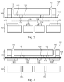
- Fig. 2 shows a system 121 comprising a microfluidic cartridge 100 and a pneumatic interface plate 101.
- a pneumatic instrument (not shown) may also be comprised.
- the interface plate may be substantially flat and may contain features for an improved sealing of the pneumatic chambers and/or may contain features which control the actuation stroke of the flexible membrane of the cartridge.
- these stroke control features 127, 128, 129 and 130 as well as 115 and 116 are integrated in the cartridge.
- Fig. 3 shows the stroke control feature 127 to 130 on the cartridge side of the pneumatic interface plate 101.
- Fig.4 shows a system 121 with a cartridge 100 and an interface plate 101 in which rubber frames 139 are part of the interface plate and recesses 140, 141 are present partly in the cartridge and partly in the interface plate.
- rubber frames are only part of the microfluidic cartridge. They may then be placed e.g. onto the microfluidic cartridge. This may e.g. be combined with a flat interface plate.
- rubber frames and recesses may both be present at the cartridge and the interface plate.
- the interface plate as described above and below may be used to hold the cartridge by applying a vacuum 131 in the areas between the actuators through the instrument interface plate.
- rubber frames 139 are applied which may also be seen in Fig 8 with reference sign 139. These rubber frames allow for a tight seal of the pneumatic chambers.
- the actuators are attached to the pneumatic channels on the bottom (instrument) side of 100. Thereby actuators are all positions where the membrane is reversibly deflected by the pneumatic system. In areas where one wants to hold the cartridge by vacuum the membrane will not be deflected. It is furthermore possible to apply another layer on the outside (on top of the membrane) to avoid delamination of the membrane by the vacuum forces.
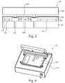
- a pneumatic instrument 102 which comprises a pneumatic interface plate 101.
- the instrument may have pneumatic switches and heaters that are integrated inside the shown box.
- pneumatic tubing l is comprised within the instrument 102, also pneumatic switches and heaters are integrated within such an instrument.
- Fig. 7 shows a system 121 according to another exemplary embodiment of the invention.
- the system consists of a pneumatic instrument 102 and a pneumatic interface plate 101, which is adapted for receiving a micro fluidic cartridge (not shown here, shown in Fig.8 ).
- Several heaters, 135, 136 are shown inside the interface plate and furthermore pneumatic channels 122, 123 and 138 are shown.
- the recesses 124, 125 and 126 can be seen from Fig. 7 .
- the shown pneumatic interface plate 101 corresponds to the interface plate shown in Fig. 2 .
- the rubber frames 139 that are also shown and described in Fig. 5 can clearly be seen.
- Fig. 8 shows a micro fluidic cartridge 100 that may for example be integrated onto the interface plate 101 of Fig. 7 may thus be inserted into the shown instrument 102.
- This corresponding cartridge of instrument 102 of Fig. 7 has 14 individual addressable valves which can be driven by the instrument shown in Fig. 7 .
- driven refers to pneumatic pumping.
- valves may be closed by applying up to 1.5 bar overpressure on the valves which enables reliable sealing of individual compartments.
- Pumping speeds of more than 1 ml in 10 seconds may be achieved. These are only examples of values. Other pressures, higher or lower and other pumping speeds, higher or lower may also be achieved.
Landscapes
- Engineering & Computer Science (AREA)
- Chemical & Material Sciences (AREA)
- General Engineering & Computer Science (AREA)
- Mechanical Engineering (AREA)
- Health & Medical Sciences (AREA)
- Dispersion Chemistry (AREA)
- Clinical Laboratory Science (AREA)
- Chemical Kinetics & Catalysis (AREA)
- Analytical Chemistry (AREA)
- General Health & Medical Sciences (AREA)
- Hematology (AREA)
- Reciprocating Pumps (AREA)
- Micromachines (AREA)
- Automatic Analysis And Handling Materials Therefor (AREA)
- Physical Or Chemical Processes And Apparatus (AREA)
- Ink Jet (AREA)
Claims (15)
- Mikrofluidische Kassette (100) für ein Platzieren auf einer parallelen pneumatischen Schnittstellenplatte (101) eines pneumatischen Instruments (102), wobei die Kassette Folgendes aufweist:einen dreidimensionalen Fluidkanal (103), in dem ein Fluid (104) zu transportieren ist,eine flexible Membran (105),wobei die flexible Membran eine Ebene überspannt,
wobei die flexible Membran Teil einer äußeren Oberfläche der Kassette ist,
wobei der dreidimensionale Fluidkanal räumlich in drei Dimensionen durch Innenwände der Kassette und durch die flexible Membran definiert ist,
wobei sich die flexible Membran in einem Grundzustand befindet, wenn kein Druck oder Vakuum auf die flexible Membran ausgeübt wird, und
wobei die flexible Membran aus ihrem Grundzustand in zwei Richtungen senkrecht (106) zur Ebene der flexiblen Membran pneumatisch auslenkbar ist, wenn die Kassette auf die parallele pneumatische Schnittstellenplatte gelegt wird,
und wobei
die flexible Membran derart an der Kassette angebracht ist, dass es möglich ist, die Kassette auf der flexiblen Membran ausschließlich durch Anbringen einer Vakuumkraft und so anzubringen, dass die Kassette, wenn auf der Schnittstellenplatte angebracht, gestattet, dass Fluide in der Kassette durch pneumatischen Antrieb der flexiblen Membran der mikrofluidischen Kassette durch die pneumatische Schnittstellenplatte angetrieben werden. - Mikrofluidische Kassette nach Anspruch 1,
wobei der Fluidkanal und die flexible Membran derart zueinander angeordnet sind, dass durch Auslenken der flexiblen Membran an mehreren Stellen (109, 110, 111, 114) entlang der flexiblen Membran durch pneumatisches Pumpen (108) des pneumatischen Instruments das Fluid von einem Anfang (112) des Fluidkanals bis zu einem Ende (113) des Fluidkanals transportiert werden kann. - Mikrofluidische Kassette nach einem der Ansprüche 1 bis 2,
wobei die Membran durch pneumatisches Pumpen des pneumatischen Instruments derart auslenkbar ist, dass die Membran den Fluidkanal schließt, um eine Ventilfunktion (114) bereitzustellen. - Mikrofluidische Kassette nach einem der Ansprüche 1 bis 3,
wobei die Kassette frei von pneumatischen Steuerelementen und frei von pneumatischen Schlauchelementen (133) ist. - Pneumatische Schnittstellenplatte (101) zur Schnittstellenbildung mit einer mikrofluidischen Kassette (100) nach einem der Ansprüche 1 bis 4 und zwischen einem pneumatischen Instrument (102) zum pneumatischen Befestigen der mikrofluidischen Kassette durch Anbringen eines Vakuums und Anwenden von pneumatischem Pumpen an der mikrofluidischen Kassette, wobei die Schnittstellenplatte Folgendes aufweist:eine Instrumentenseite (119), die zum Gerät gerichtet ist, wenn die Schnittstellenplatte in das Gerät eingesetzt wird,eine Kassettenseite, die zur Kassette gerichtet ist, wenn die Kassette auf der Schnittstellenplatte angeordnet wird,einen pneumatischen Kanal (122, 123, 138) zum Verbinden eines pneumatischen Fluids des pneumatischen Instruments von der Instrumentenseite zur Kassettenseite, um einen pneumatischen Antrieb der flexiblen Membran der mikrofluidischen Kassette zu ermöglichen.
- Pneumatische Schnittstellenplatte nach Anspruch 5,
wobei die Kassettenseite mindestens eine Aussparung (124, 125, 126) zum Einsaugen der flexiblen Membran der Kassette, wenn die Membran mit einem Unterdruck beaufschlagt wird. - Pneumatische Schnittstellenplatte nach einem der Ansprüche 5 oder 6,
wobei die Schnittstellenplatte mindestens ein Element ist, das ausgewählt ist aus der Gruppe bestehend aus einer Wärmeerzeugungsvorrichtung (135, 136), einem aus Aluminium Wärmeübertragungselement, einem aus Kupfer hergestellten Wärmeübertragungselement, einem aus einer Legierung aus Aluminium und/oder Kupfer hergestellten Wärmeübertragungselement, einer sich bis zur mikrofluidischen Kassette erstreckenden Wärmeübertragungselemente aufweisenden Wärmeerzeugungsvorrichtung, einer akustische Energie erzeugenden Vorrichtung, einer Vorrichtung zum Behandeln des Fluids mit fokussiertem oder unfokussiertem Ultraschall, einem Piezoaktor, einem mechanischen Stellglied, einem magnetischen Stellglied und jeder Kombination davon. - Pneumatische Schnittstellenplatte nach einem der Ansprüche 5 bis 7,
wobei die Schnittstellenplatte aus einem Material hergestellt ist, das ausgewählt ist aus der Gruppe bestehend aus Stahl, Edelstahl, Glas, Elastomer, Polymer, anderen chemisch beständigen und mäßig wärmeleitenden Materialien und jeder Kombination davon. - System (121) für die Fluidbetätigung innerhalb einer mikrofluidischen Kassette, wobei das System Folgendes umfasst:eine mikrofluidische Kassette nach einem der Ansprüche 1 bis 4,eine pneumatische Schnittstellenplatte nach einem der Ansprüche 5 bis 8, wobei die flexible Membran der Kassette durch pneumatisches Pumpen durch den pneumatischen Kanal der Schnittstellenplatte in solcher Weise auslenkbar ist, dass ein Fluid im Fluidkanal entlang dem Fluidkanal bewegbar ist.
- System nach Anspruch 9,
wobei die Kassette und die pneumatische Schnittstellenplatte zwei physikalisch getrennte Komponenten sind, die für die Fluidbetätigung nur durch pneumatische Kräfte reversibel zusammengehalten werden. - System nach einem der Ansprüche 9 oder 10,
wobei die flexible Membran und die Kassettenseite der Schnittstellenplatte in Kombination auf solche angepasst sind, dass unter Beaufschlagung mit Druck durch einen Luftkanal der pneumatischen Schnittstellenplatte die Kassette vollständig an der pneumatischen Schnittstellenplatte befestigt ist. - System nach einem der Ansprüche 9 bis 11, wobei das System ferner Folgendes umfasst:das pneumatische Instrument zum pneumatischen Pumpen zur mikrofluidische Kassette.
- System nach einem der Ansprüche 9 bis 12, wobei das System ferner Folgendes umfasst:Steuereinrichtungen (115, 116),wobei die Steuerfunktionen oberhalb und unterhalb der flexiblen Membran angeordnet sind,wobei die Steuerfunktionen oberhalb der flexiblen Membran als Hindernisse für einen Fluidtransport innerhalb des Fluidkanals angeordnet sind, undwobei die flexible Membran mechanisch von den Steuerfunktionen auf solche Weise unterstützt wird, dass die Membran während des pneumatischen Pumpens auf solche Weise ausgelenkt wird, dass die Hindernisse durch das Fluid umgangen werden können.
- System nach einem der Ansprüche 9 bis 13,
wobei pneumatische Kammern zwischen der flexiblen Membran und der Schnittstellenplatte reversibel zusammengebaut werden. - Pneumatisches Instrument (102) zum Bewirken eines pneumatischen Pumpens zu einer mikrofluidischen Kassette (100) für einen Fluidtransport innerhalb der mikrofluidischen Kassette, wobei das pneumatische Instrument Folgendes aufweist:Mittel zum pneumatischen Betätigen einer flexiblen Membran der mikrofluidischen Kassette, undeine pneumatische Schnittstellenplatte nach den Ansprüchen 5 bis 8.
Priority Applications (2)
| Application Number | Priority Date | Filing Date | Title |
|---|---|---|---|
| EP16158136.8A EP3050626A1 (de) | 2009-10-21 | 2010-10-06 | Mikrofluidische kassette mit paralleler pneumatischer schnittstellenplatte |
| EP10771203.6A EP2490812B1 (de) | 2009-10-21 | 2010-10-06 | Mikrofluidische kassette mit paralleler pneumatischer schnittstellenplatte |
Applications Claiming Priority (3)
| Application Number | Priority Date | Filing Date | Title |
|---|---|---|---|
| EP09173589 | 2009-10-21 | ||
| EP10771203.6A EP2490812B1 (de) | 2009-10-21 | 2010-10-06 | Mikrofluidische kassette mit paralleler pneumatischer schnittstellenplatte |
| PCT/IB2010/054520 WO2011048521A1 (en) | 2009-10-21 | 2010-10-06 | Microfluidic cartridge with parallel pneumatic interface plate |
Related Child Applications (2)
| Application Number | Title | Priority Date | Filing Date |
|---|---|---|---|
| EP16158136.8A Division-Into EP3050626A1 (de) | 2009-10-21 | 2010-10-06 | Mikrofluidische kassette mit paralleler pneumatischer schnittstellenplatte |
| EP16158136.8A Division EP3050626A1 (de) | 2009-10-21 | 2010-10-06 | Mikrofluidische kassette mit paralleler pneumatischer schnittstellenplatte |
Publications (2)
| Publication Number | Publication Date |
|---|---|
| EP2490812A1 EP2490812A1 (de) | 2012-08-29 |
| EP2490812B1 true EP2490812B1 (de) | 2016-05-11 |
Family
ID=43416568
Family Applications (2)
| Application Number | Title | Priority Date | Filing Date |
|---|---|---|---|
| EP10771203.6A Active EP2490812B1 (de) | 2009-10-21 | 2010-10-06 | Mikrofluidische kassette mit paralleler pneumatischer schnittstellenplatte |
| EP16158136.8A Withdrawn EP3050626A1 (de) | 2009-10-21 | 2010-10-06 | Mikrofluidische kassette mit paralleler pneumatischer schnittstellenplatte |
Family Applications After (1)
| Application Number | Title | Priority Date | Filing Date |
|---|---|---|---|
| EP16158136.8A Withdrawn EP3050626A1 (de) | 2009-10-21 | 2010-10-06 | Mikrofluidische kassette mit paralleler pneumatischer schnittstellenplatte |
Country Status (12)
| Country | Link |
|---|---|
| US (1) | US9044752B2 (de) |
| EP (2) | EP2490812B1 (de) |
| JP (1) | JP5456904B2 (de) |
| KR (1) | KR101472581B1 (de) |
| CN (1) | CN102665915B (de) |
| AU (1) | AU2010309456B2 (de) |
| BR (1) | BR112012009300A2 (de) |
| CA (1) | CA2777445C (de) |
| ES (1) | ES2578778T3 (de) |
| RU (1) | RU2542235C2 (de) |
| WO (1) | WO2011048521A1 (de) |
| ZA (1) | ZA201202864B (de) |
Cited By (1)
| Publication number | Priority date | Publication date | Assignee | Title |
|---|---|---|---|---|
| DE102018204633A1 (de) | 2018-03-27 | 2019-10-02 | Robert Bosch Gmbh | Mikrofluidische Vorrichtung und Verfahren zum Prozessieren einer Flüssigkeit |
Families Citing this family (61)
| Publication number | Priority date | Publication date | Assignee | Title |
|---|---|---|---|---|
| CN103977848B (zh) | 2007-04-06 | 2016-08-24 | 加利福尼亚技术学院 | 微流体装置 |
| WO2013134739A1 (en) | 2012-03-08 | 2013-09-12 | Cyvek, Inc. | Microfluidic assay operating system and methods of use |
| US10065403B2 (en) | 2009-11-23 | 2018-09-04 | Cyvek, Inc. | Microfluidic assay assemblies and methods of manufacture |
| US9855735B2 (en) | 2009-11-23 | 2018-01-02 | Cyvek, Inc. | Portable microfluidic assay devices and methods of manufacture and use |
| US10022696B2 (en) | 2009-11-23 | 2018-07-17 | Cyvek, Inc. | Microfluidic assay systems employing micro-particles and methods of manufacture |
| US9700889B2 (en) | 2009-11-23 | 2017-07-11 | Cyvek, Inc. | Methods and systems for manufacture of microarray assay systems, conducting microfluidic assays, and monitoring and scanning to obtain microfluidic assay results |
| CA2781556C (en) | 2009-11-23 | 2015-05-19 | Cyvek, Inc. | Method and apparatus for performing assays |
| US9759718B2 (en) | 2009-11-23 | 2017-09-12 | Cyvek, Inc. | PDMS membrane-confined nucleic acid and antibody/antigen-functionalized microlength tube capture elements, and systems employing them, and methods of their use |
| US9500645B2 (en) | 2009-11-23 | 2016-11-22 | Cyvek, Inc. | Micro-tube particles for microfluidic assays and methods of manufacture |
| CN103649759B (zh) | 2011-03-22 | 2016-08-31 | 西维克公司 | 微流体装置以及制造方法和用途 |
| EP2532433A1 (de) * | 2011-06-06 | 2012-12-12 | Koninklijke Philips Electronics N.V. | Vorrichtung zum Fragmentieren von Molekülen einer Probe durch Ultraschall |
| DE102011114554A1 (de) * | 2011-09-30 | 2013-04-04 | Fraunhofer-Gesellschaft zur Förderung der angewandten Forschung e.V. | Verfahren und Vorrichtung zum Dosiereneines inkompressiblen Arbeitsfluids |
| EP2610009A1 (de) * | 2011-12-29 | 2013-07-03 | Samsung Electronics Co., Ltd | Festreagenzienauflösungsvorrichtung und Verfahren zur Auflösung von Festreagenzien durch Verwendung davon |
| CN103184143A (zh) * | 2011-12-29 | 2013-07-03 | 三星电子株式会社 | 固体试剂溶解器件以及使用其溶解固体试剂的方法 |
| EP2684609A1 (de) | 2012-07-09 | 2014-01-15 | Biocartis SA | Heizgerät für eine Einweg-Diagnosekartuschen |
| US20140170678A1 (en) | 2012-12-17 | 2014-06-19 | Leukodx Ltd. | Kits, compositions and methods for detecting a biological condition |
| EP3508848B1 (de) | 2012-12-17 | 2022-10-05 | Accellix Ltd | Systeme und verfahren zur bestimmung eines chemischen zustandes |
| US10246675B2 (en) | 2013-01-31 | 2019-04-02 | Hitachi High-Technologies Corporation | Biochemical cartridge, and biochemical cartridge and cartridge holder set |
| JP6202713B2 (ja) * | 2013-02-22 | 2017-09-27 | 株式会社日立ハイテクノロジーズ | 生化学用カートリッジおよび生化学用送液システム |
| KR101409812B1 (ko) * | 2013-05-14 | 2014-06-24 | 한국기계연구원 | 자유지지형 나노박막의 물성 시험 장치 및 방법 |
| WO2015022176A1 (en) | 2013-08-12 | 2015-02-19 | Koninklijke Philips N.V. | Microfluidic device with valve |
| DE102013219502A1 (de) | 2013-09-27 | 2015-04-02 | Robert Bosch Gmbh | Analyseeinheit zum Durchführen einer Polymerasekettenreaktion, Verfahren zum Betreiben einer solchen Analyseeinheit und Verfahren zum Herstellen einer solchen Analyseeinheit |
| CN105873681B (zh) * | 2013-11-18 | 2019-10-11 | 尹特根埃克斯有限公司 | 用于样本分析的卡盒和仪器 |
| CN104315232B (zh) * | 2014-08-20 | 2018-01-09 | 中国检验检疫科学研究院 | 微流体微阀驱动装置 |
| CN104315241B (zh) * | 2014-08-20 | 2018-01-09 | 中国检验检疫科学研究院 | 微流体微阀及驱动装置 |
| US10166542B2 (en) | 2014-09-17 | 2019-01-01 | Arizona Board Of Regents On Behalf Of Arizona State University | Methods, systems and apparatus for microfluidic crystallization based on gradient mixing |
| CN105057013A (zh) * | 2015-07-30 | 2015-11-18 | 华南理工大学 | 一种基于空间选择性诱导玻璃分相制备三维连通微通道的方法 |
| FR3040141B1 (fr) * | 2015-08-20 | 2020-02-14 | Commissariat A L'energie Atomique Et Aux Energies Alternatives | Carte fluidique comportant au moins une vanne fluidique |
| CN105201796A (zh) * | 2015-10-29 | 2015-12-30 | 宁波大学 | 一种压电蠕动微泵 |
| US10228367B2 (en) | 2015-12-01 | 2019-03-12 | ProteinSimple | Segmented multi-use automated assay cartridge |
| TWI789343B (zh) | 2016-02-01 | 2023-01-11 | 丹麥商碩騰丹麥有限公司 | 微流體分析系統、執行分析的微流體匣及方法 |
| ITUB20161080A1 (it) * | 2016-02-25 | 2017-08-25 | St Microelectronics Srl | Dispositivo sensore di pressione di tipo micro-elettro-meccanico con ridotta sensibilita' alla temperatura |
| EP3222351A1 (de) | 2016-03-23 | 2017-09-27 | Ecole Polytechnique Fédérale de Lausanne (EPFL) | Mikrofluidische netzwerkvorrichtung |
| CN109475864B (zh) * | 2016-06-29 | 2022-03-04 | 美天施生物科技有限两合公司 | 用于生物试样的多级一次性筒 |
| GB2554377A (en) * | 2016-09-23 | 2018-04-04 | Dnanudge Ltd | Method and apparatus for analysing a biological sample |
| CA3036789A1 (en) | 2016-10-07 | 2018-04-12 | Boehringer Ingelheim Vetmedica Gmbh | Cartridge, analysis system and method for testing a sample |
| WO2018104516A1 (en) * | 2016-12-08 | 2018-06-14 | Danmarks Tekniske Universitet | Microfluidic valve |
| CN108217576B (zh) * | 2016-12-21 | 2020-05-22 | 上海傲睿科技有限公司 | 膜片截止阀及其制造方法 |
| WO2018217793A1 (en) | 2017-05-22 | 2018-11-29 | Arizona Board Of Regents On Behalf Of Arizona State University | 3d printed microfluidic mixers and nozzles for crystallography |
| WO2018217831A1 (en) | 2017-05-22 | 2018-11-29 | Arizona Board Of Regents On Behalf Of Arizona State University | Metal electrode based 3d printed device for tuning microfluidic droplet generation frequency and synchronizing phase for serial femtosecond crystallography |
| US10422362B2 (en) | 2017-09-05 | 2019-09-24 | Facebook Technologies, Llc | Fluidic pump and latch gate |
| EP3459632A1 (de) | 2017-09-26 | 2019-03-27 | Lunaphore Technologies SA | Mikrofluidische kartusche mit eingebauter abtastvorrichtung |
| US10591933B1 (en) | 2017-11-10 | 2020-03-17 | Facebook Technologies, Llc | Composable PFET fluidic device |
| US11173487B2 (en) | 2017-12-19 | 2021-11-16 | Arizona Board Of Regents On Behalf Of Arizona State University | Deterministic ratchet for sub-micrometer bioparticle separation |
| KR102201719B1 (ko) * | 2018-01-17 | 2021-01-12 | 한국과학기술원 | 손가락 구동 기반 미세유체 제어를 이용한 랩온어칩 시스템 및 그 용도 |
| US10307755B1 (en) | 2018-07-19 | 2019-06-04 | Bioceryx Inc. | Apparatuses and methods for sample-specific self-configuration |
| WO2020032979A1 (en) * | 2018-08-10 | 2020-02-13 | Hewlett-Packard Development Company, L.P. | Dual direction dispensers |
| US10962124B1 (en) * | 2019-03-29 | 2021-03-30 | Facebook Technologies, Llc | Fluidic latches, systems, and methods |
| US11318487B2 (en) | 2019-05-14 | 2022-05-03 | Arizona Board Of Regents On Behalf Of Arizona State University | Co-flow injection for serial crystallography |
| US11624718B2 (en) | 2019-05-14 | 2023-04-11 | Arizona Board Of Regents On Behalf Of Arizona State University | Single piece droplet generation and injection device for serial crystallography |
| CN110018132A (zh) * | 2019-05-20 | 2019-07-16 | 北京航空航天大学青岛研究院 | 一种自旋生物传感器及太赫兹时域光谱系统 |
| CN110244362B (zh) * | 2019-06-18 | 2021-04-06 | 湖南普奇地质勘探设备研究院(普通合伙) | 一种阵列式拾音器管道定位装置及方法 |
| US12031970B2 (en) | 2020-04-30 | 2024-07-09 | Precision Planting Llc | Agricultural sampling system and related methods |
| DE102020210536A1 (de) | 2020-08-19 | 2022-02-24 | Robert Bosch Gesellschaft mit beschränkter Haftung | Mikrofluidische Vorrichtung |
| US11485632B2 (en) | 2020-10-09 | 2022-11-01 | Arizona Board Of Regents On Behalf Of Arizona State University | Modular 3-D printed devices for sample delivery and method |
| KR20230149808A (ko) * | 2020-12-24 | 2023-10-27 | 인비보스크라이브, 아이엔씨. | 화학 처리 시스템, 기기 및 샘플 카트리지 |
| CN113546700B (zh) * | 2021-05-21 | 2022-10-04 | 宁波胤瑞生物医学仪器有限责任公司 | 一种芯片压紧装置 |
| US20230302446A1 (en) * | 2022-03-25 | 2023-09-28 | Seegeme. Inc. | Cartridge for detecting target analyte |
| DE102022204074A1 (de) | 2022-04-27 | 2023-11-02 | Robert Bosch Gesellschaft mit beschränkter Haftung | Dichteinsatz, Maske und mikrofluidische Vorrichtung |
| CN119546391A (zh) * | 2022-08-02 | 2025-02-28 | 伊鲁米那有限公司 | 非接触式分配器以及相关系统和方法 |
| CN119752606A (zh) * | 2025-01-09 | 2025-04-04 | 重庆科标计量检测有限公司 | 一种组合式荧光定量pcr装置及其使用方法 |
Family Cites Families (19)
| Publication number | Priority date | Publication date | Assignee | Title |
|---|---|---|---|---|
| US4119120A (en) * | 1976-11-29 | 1978-10-10 | Beckman Instruments, Inc. | Fluid switch |
| US5083742A (en) * | 1990-08-01 | 1992-01-28 | Photovac Incorporated | Fluid control valve |
| IT1255014B (it) * | 1992-03-27 | 1995-10-13 | Instrumentation Lab Spa | Dispositivi di movimentazione ed intercettazione di fluidi |
| US5593290A (en) * | 1994-12-22 | 1997-01-14 | Eastman Kodak Company | Micro dispensing positive displacement pump |
| US5863801A (en) * | 1996-06-14 | 1999-01-26 | Sarnoff Corporation | Automated nucleic acid isolation |
| AU2002307152A1 (en) * | 2001-04-06 | 2002-10-21 | California Institute Of Technology | Nucleic acid amplification utilizing microfluidic devices |
| US7008193B2 (en) * | 2002-05-13 | 2006-03-07 | The Regents Of The University Of Michigan | Micropump assembly for a microgas chromatograph and the like |
| DE10238600A1 (de) * | 2002-08-22 | 2004-03-04 | Fraunhofer-Gesellschaft zur Förderung der angewandten Forschung e.V. | Peristaltische Mikropumpe |
| EP1403519A1 (de) * | 2002-09-27 | 2004-03-31 | Novo Nordisk A/S | Membranpumpe mit dehnbarer Pumpenmembran |
| US7284966B2 (en) * | 2003-10-01 | 2007-10-23 | Agency For Science, Technology & Research | Micro-pump |
| US7832429B2 (en) * | 2004-10-13 | 2010-11-16 | Rheonix, Inc. | Microfluidic pump and valve structures and fabrication methods |
| US7938573B2 (en) * | 2005-09-02 | 2011-05-10 | Genefluidics, Inc. | Cartridge having variable volume reservoirs |
| US7976795B2 (en) * | 2006-01-19 | 2011-07-12 | Rheonix, Inc. | Microfluidic systems |
| DE102006030068A1 (de) * | 2006-06-28 | 2008-01-03 | M2P-Labs Gmbh | Vorrichtung und Verfahren zur Zu- und Abfuhr von Fluiden in geschüttelten Mikroreaktoren Arrays |
| JP2010513790A (ja) * | 2006-12-19 | 2010-04-30 | コーニンクレッカ フィリップス エレクトロニクス エヌ ヴィ | マイクロ流体装置 |
| JP2008202950A (ja) * | 2007-02-16 | 2008-09-04 | Kawamura Inst Of Chem Res | 温調装置、温調機構を有するマイクロ流体デバイス、及び温調方法 |
| JP5001203B2 (ja) * | 2008-03-18 | 2012-08-15 | アイダエンジニアリング株式会社 | 非接着部を有するマイクロチップの製造方法 |
| EP2367634A1 (de) * | 2008-12-24 | 2011-09-28 | Heriot-Watt University | Mikrofluidsystem und -verfahren |
| JP5355145B2 (ja) * | 2009-02-26 | 2013-11-27 | シスメックス株式会社 | 試薬調製装置、検体測定装置および試薬調製方法 |
-
2010
- 2010-10-06 EP EP10771203.6A patent/EP2490812B1/de active Active
- 2010-10-06 RU RU2012120796/05A patent/RU2542235C2/ru not_active IP Right Cessation
- 2010-10-06 US US13/503,322 patent/US9044752B2/en active Active
- 2010-10-06 EP EP16158136.8A patent/EP3050626A1/de not_active Withdrawn
- 2010-10-06 WO PCT/IB2010/054520 patent/WO2011048521A1/en not_active Ceased
- 2010-10-06 KR KR1020127010152A patent/KR101472581B1/ko not_active Expired - Fee Related
- 2010-10-06 CN CN201080047861.5A patent/CN102665915B/zh active Active
- 2010-10-06 ES ES10771203.6T patent/ES2578778T3/es active Active
- 2010-10-06 JP JP2012534801A patent/JP5456904B2/ja active Active
- 2010-10-06 BR BR112012009300-2A patent/BR112012009300A2/pt not_active Application Discontinuation
- 2010-10-06 CA CA 2777445 patent/CA2777445C/en not_active Expired - Fee Related
- 2010-10-06 AU AU2010309456A patent/AU2010309456B2/en not_active Ceased
-
2012
- 2012-04-18 ZA ZA2012/02864A patent/ZA201202864B/en unknown
Non-Patent Citations (1)
| Title |
|---|
| None * |
Cited By (2)
| Publication number | Priority date | Publication date | Assignee | Title |
|---|---|---|---|---|
| DE102018204633A1 (de) | 2018-03-27 | 2019-10-02 | Robert Bosch Gmbh | Mikrofluidische Vorrichtung und Verfahren zum Prozessieren einer Flüssigkeit |
| US11583857B2 (en) | 2018-03-27 | 2023-02-21 | Robert Bosch Gmbh | Microfluidic device for processing a liquid |
Also Published As
| Publication number | Publication date |
|---|---|
| ZA201202864B (en) | 2012-12-27 |
| WO2011048521A1 (en) | 2011-04-28 |
| ES2578778T3 (es) | 2016-08-01 |
| EP3050626A1 (de) | 2016-08-03 |
| KR20130058654A (ko) | 2013-06-04 |
| BR112012009300A2 (pt) | 2020-08-18 |
| AU2010309456B2 (en) | 2013-09-05 |
| CA2777445A1 (en) | 2011-04-28 |
| CN102665915A (zh) | 2012-09-12 |
| US9044752B2 (en) | 2015-06-02 |
| RU2012120796A (ru) | 2013-11-27 |
| JP2013508715A (ja) | 2013-03-07 |
| US20120266986A1 (en) | 2012-10-25 |
| JP5456904B2 (ja) | 2014-04-02 |
| KR101472581B1 (ko) | 2014-12-16 |
| AU2010309456A1 (en) | 2012-05-17 |
| CA2777445C (en) | 2014-08-05 |
| RU2542235C2 (ru) | 2015-02-20 |
| EP2490812A1 (de) | 2012-08-29 |
| CN102665915B (zh) | 2016-02-10 |
Similar Documents
| Publication | Publication Date | Title |
|---|---|---|
| EP2490812B1 (de) | Mikrofluidische kassette mit paralleler pneumatischer schnittstellenplatte | |
| EP2665956B1 (de) | Mikropumpe oder normal-aus-mikroventil | |
| US8950424B2 (en) | Device for transporting small volumes of a fluid, in particular a micropump or microvalve | |
| US7892496B2 (en) | Mechanically-actuated microfluidic pinch valve | |
| US8092761B2 (en) | Mechanically-actuated microfluidic diaphragm valve | |
| EP2606975B1 (de) | Mikrofluidische Vorrichtung mit Flüssigkeitsmess-Ladesystem für eine mikrofluidische Vorrichtung | |
| CN107620804B (zh) | 流体控制装置 | |
| US8062612B2 (en) | MEMS integrated circuit comprising microfluidic diaphragm valve | |
| AU2012208527A1 (en) | Micro-pump or normally-off micro-valve | |
| US7981386B2 (en) | Mechanically-actuated microfluidic valve | |
| US20090317273A1 (en) | Thermal Bend Actuated Microfluidic Peristaltic Pump | |
| US20090314368A1 (en) | Microfluidic System Comprising Pinch Valve and On-Chip MEMS Pump | |
| US8075855B2 (en) | MEMS integrated circuit comprising peristaltic microfluidic pump | |
| US20090317302A1 (en) | Microfluidic System Comprising MEMS Integrated Circuit | |
| US20090315126A1 (en) | Bonded Microfluidic System Comprising Thermal Bend Actuated Valve | |
| KR20100124827A (ko) | Cmos-제어 가능한 미세유체 장치를 포함하는 결합형 미세유체 시스템 | |
| US20240159325A1 (en) | Actuation unit for a multi valve device and multi valve device | |
| US20090314367A1 (en) | Bonded Microfluidics System Comprising CMOS-Controllable Microfluidic Devices | |
| US20090317301A1 (en) | Bonded Microfluidics System Comprising MEMS-Actuated Microfluidic Devices |
Legal Events
| Date | Code | Title | Description |
|---|---|---|---|
| PUAI | Public reference made under article 153(3) epc to a published international application that has entered the european phase |
Free format text: ORIGINAL CODE: 0009012 |
|
| 17P | Request for examination filed |
Effective date: 20120420 |
|
| AK | Designated contracting states |
Kind code of ref document: A1 Designated state(s): AL AT BE BG CH CY CZ DE DK EE ES FI FR GB GR HR HU IE IS IT LI LT LU LV MC MK MT NL NO PL PT RO RS SE SI SK SM TR |
|
| DAX | Request for extension of the european patent (deleted) | ||
| RAP1 | Party data changed (applicant data changed or rights of an application transferred) |
Owner name: BIOCARTIS NV |
|
| 17Q | First examination report despatched |
Effective date: 20140902 |
|
| GRAP | Despatch of communication of intention to grant a patent |
Free format text: ORIGINAL CODE: EPIDOSNIGR1 |
|
| INTG | Intention to grant announced |
Effective date: 20151202 |
|
| GRAS | Grant fee paid |
Free format text: ORIGINAL CODE: EPIDOSNIGR3 |
|
| GRAR | Information related to intention to grant a patent recorded |
Free format text: ORIGINAL CODE: EPIDOSNIGR71 |
|
| GRAA | (expected) grant |
Free format text: ORIGINAL CODE: 0009210 |
|
| INTG | Intention to grant announced |
Effective date: 20160331 |
|
| AK | Designated contracting states |
Kind code of ref document: B1 Designated state(s): AL AT BE BG CH CY CZ DE DK EE ES FI FR GB GR HR HU IE IS IT LI LT LU LV MC MK MT NL NO PL PT RO RS SE SI SK SM TR |
|
| REG | Reference to a national code |
Ref country code: GB Ref legal event code: FG4D |
|
| REG | Reference to a national code |
Ref country code: CH Ref legal event code: EP |
|
| REG | Reference to a national code |
Ref country code: AT Ref legal event code: REF Ref document number: 798204 Country of ref document: AT Kind code of ref document: T Effective date: 20160515 |
|
| REG | Reference to a national code |
Ref country code: IE Ref legal event code: FG4D |
|
| REG | Reference to a national code |
Ref country code: DE Ref legal event code: R096 Ref document number: 602010033321 Country of ref document: DE |
|
| REG | Reference to a national code |
Ref country code: NL Ref legal event code: FP |
|
| REG | Reference to a national code |
Ref country code: ES Ref legal event code: FG2A Ref document number: 2578778 Country of ref document: ES Kind code of ref document: T3 Effective date: 20160801 |
|
| REG | Reference to a national code |
Ref country code: LT Ref legal event code: MG4D |
|
| REG | Reference to a national code |
Ref country code: FR Ref legal event code: PLFP Year of fee payment: 7 |
|
| PG25 | Lapsed in a contracting state [announced via postgrant information from national office to epo] |
Ref country code: FI Free format text: LAPSE BECAUSE OF FAILURE TO SUBMIT A TRANSLATION OF THE DESCRIPTION OR TO PAY THE FEE WITHIN THE PRESCRIBED TIME-LIMIT Effective date: 20160511 Ref country code: NO Free format text: LAPSE BECAUSE OF FAILURE TO SUBMIT A TRANSLATION OF THE DESCRIPTION OR TO PAY THE FEE WITHIN THE PRESCRIBED TIME-LIMIT Effective date: 20160811 Ref country code: LT Free format text: LAPSE BECAUSE OF FAILURE TO SUBMIT A TRANSLATION OF THE DESCRIPTION OR TO PAY THE FEE WITHIN THE PRESCRIBED TIME-LIMIT Effective date: 20160511 |
|
| REG | Reference to a national code |
Ref country code: AT Ref legal event code: MK05 Ref document number: 798204 Country of ref document: AT Kind code of ref document: T Effective date: 20160511 |
|
| PG25 | Lapsed in a contracting state [announced via postgrant information from national office to epo] |
Ref country code: SE Free format text: LAPSE BECAUSE OF FAILURE TO SUBMIT A TRANSLATION OF THE DESCRIPTION OR TO PAY THE FEE WITHIN THE PRESCRIBED TIME-LIMIT Effective date: 20160511 Ref country code: PT Free format text: LAPSE BECAUSE OF FAILURE TO SUBMIT A TRANSLATION OF THE DESCRIPTION OR TO PAY THE FEE WITHIN THE PRESCRIBED TIME-LIMIT Effective date: 20160912 Ref country code: LV Free format text: LAPSE BECAUSE OF FAILURE TO SUBMIT A TRANSLATION OF THE DESCRIPTION OR TO PAY THE FEE WITHIN THE PRESCRIBED TIME-LIMIT Effective date: 20160511 Ref country code: HR Free format text: LAPSE BECAUSE OF FAILURE TO SUBMIT A TRANSLATION OF THE DESCRIPTION OR TO PAY THE FEE WITHIN THE PRESCRIBED TIME-LIMIT Effective date: 20160511 Ref country code: RS Free format text: LAPSE BECAUSE OF FAILURE TO SUBMIT A TRANSLATION OF THE DESCRIPTION OR TO PAY THE FEE WITHIN THE PRESCRIBED TIME-LIMIT Effective date: 20160511 Ref country code: GR Free format text: LAPSE BECAUSE OF FAILURE TO SUBMIT A TRANSLATION OF THE DESCRIPTION OR TO PAY THE FEE WITHIN THE PRESCRIBED TIME-LIMIT Effective date: 20160812 |
|
| PG25 | Lapsed in a contracting state [announced via postgrant information from national office to epo] |
Ref country code: SK Free format text: LAPSE BECAUSE OF FAILURE TO SUBMIT A TRANSLATION OF THE DESCRIPTION OR TO PAY THE FEE WITHIN THE PRESCRIBED TIME-LIMIT Effective date: 20160511 Ref country code: EE Free format text: LAPSE BECAUSE OF FAILURE TO SUBMIT A TRANSLATION OF THE DESCRIPTION OR TO PAY THE FEE WITHIN THE PRESCRIBED TIME-LIMIT Effective date: 20160511 Ref country code: RO Free format text: LAPSE BECAUSE OF FAILURE TO SUBMIT A TRANSLATION OF THE DESCRIPTION OR TO PAY THE FEE WITHIN THE PRESCRIBED TIME-LIMIT Effective date: 20160511 Ref country code: DK Free format text: LAPSE BECAUSE OF FAILURE TO SUBMIT A TRANSLATION OF THE DESCRIPTION OR TO PAY THE FEE WITHIN THE PRESCRIBED TIME-LIMIT Effective date: 20160511 Ref country code: CZ Free format text: LAPSE BECAUSE OF FAILURE TO SUBMIT A TRANSLATION OF THE DESCRIPTION OR TO PAY THE FEE WITHIN THE PRESCRIBED TIME-LIMIT Effective date: 20160511 |
|
| REG | Reference to a national code |
Ref country code: DE Ref legal event code: R097 Ref document number: 602010033321 Country of ref document: DE |
|
| PG25 | Lapsed in a contracting state [announced via postgrant information from national office to epo] |
Ref country code: PL Free format text: LAPSE BECAUSE OF FAILURE TO SUBMIT A TRANSLATION OF THE DESCRIPTION OR TO PAY THE FEE WITHIN THE PRESCRIBED TIME-LIMIT Effective date: 20160511 Ref country code: SM Free format text: LAPSE BECAUSE OF FAILURE TO SUBMIT A TRANSLATION OF THE DESCRIPTION OR TO PAY THE FEE WITHIN THE PRESCRIBED TIME-LIMIT Effective date: 20160511 Ref country code: AT Free format text: LAPSE BECAUSE OF FAILURE TO SUBMIT A TRANSLATION OF THE DESCRIPTION OR TO PAY THE FEE WITHIN THE PRESCRIBED TIME-LIMIT Effective date: 20160511 |
|
| PLBE | No opposition filed within time limit |
Free format text: ORIGINAL CODE: 0009261 |
|
| STAA | Information on the status of an ep patent application or granted ep patent |
Free format text: STATUS: NO OPPOSITION FILED WITHIN TIME LIMIT |
|
| 26N | No opposition filed |
Effective date: 20170214 |
|
| PG25 | Lapsed in a contracting state [announced via postgrant information from national office to epo] |
Ref country code: SI Free format text: LAPSE BECAUSE OF FAILURE TO SUBMIT A TRANSLATION OF THE DESCRIPTION OR TO PAY THE FEE WITHIN THE PRESCRIBED TIME-LIMIT Effective date: 20160511 |
|
| PG25 | Lapsed in a contracting state [announced via postgrant information from national office to epo] |
Ref country code: MC Free format text: LAPSE BECAUSE OF FAILURE TO SUBMIT A TRANSLATION OF THE DESCRIPTION OR TO PAY THE FEE WITHIN THE PRESCRIBED TIME-LIMIT Effective date: 20160511 |
|
| REG | Reference to a national code |
Ref country code: IE Ref legal event code: MM4A |
|
| PG25 | Lapsed in a contracting state [announced via postgrant information from national office to epo] |
Ref country code: LU Free format text: LAPSE BECAUSE OF NON-PAYMENT OF DUE FEES Effective date: 20161006 |
|
| REG | Reference to a national code |
Ref country code: FR Ref legal event code: PLFP Year of fee payment: 8 |
|
| PG25 | Lapsed in a contracting state [announced via postgrant information from national office to epo] |
Ref country code: IE Free format text: LAPSE BECAUSE OF NON-PAYMENT OF DUE FEES Effective date: 20161006 |
|
| PG25 | Lapsed in a contracting state [announced via postgrant information from national office to epo] |
Ref country code: HU Free format text: LAPSE BECAUSE OF FAILURE TO SUBMIT A TRANSLATION OF THE DESCRIPTION OR TO PAY THE FEE WITHIN THE PRESCRIBED TIME-LIMIT; INVALID AB INITIO Effective date: 20101006 Ref country code: CY Free format text: LAPSE BECAUSE OF FAILURE TO SUBMIT A TRANSLATION OF THE DESCRIPTION OR TO PAY THE FEE WITHIN THE PRESCRIBED TIME-LIMIT Effective date: 20160511 |
|
| PG25 | Lapsed in a contracting state [announced via postgrant information from national office to epo] |
Ref country code: MT Free format text: LAPSE BECAUSE OF NON-PAYMENT OF DUE FEES Effective date: 20161031 Ref country code: MK Free format text: LAPSE BECAUSE OF FAILURE TO SUBMIT A TRANSLATION OF THE DESCRIPTION OR TO PAY THE FEE WITHIN THE PRESCRIBED TIME-LIMIT Effective date: 20160511 Ref country code: IS Free format text: LAPSE BECAUSE OF FAILURE TO SUBMIT A TRANSLATION OF THE DESCRIPTION OR TO PAY THE FEE WITHIN THE PRESCRIBED TIME-LIMIT Effective date: 20160511 |
|
| PG25 | Lapsed in a contracting state [announced via postgrant information from national office to epo] |
Ref country code: BG Free format text: LAPSE BECAUSE OF FAILURE TO SUBMIT A TRANSLATION OF THE DESCRIPTION OR TO PAY THE FEE WITHIN THE PRESCRIBED TIME-LIMIT Effective date: 20160511 |
|
| PG25 | Lapsed in a contracting state [announced via postgrant information from national office to epo] |
Ref country code: AL Free format text: LAPSE BECAUSE OF FAILURE TO SUBMIT A TRANSLATION OF THE DESCRIPTION OR TO PAY THE FEE WITHIN THE PRESCRIBED TIME-LIMIT Effective date: 20160511 |
|
| REG | Reference to a national code |
Ref country code: FR Ref legal event code: PLFP Year of fee payment: 9 |
|
| PGFP | Annual fee paid to national office [announced via postgrant information from national office to epo] |
Ref country code: TR Payment date: 20180924 Year of fee payment: 9 |
|
| PGFP | Annual fee paid to national office [announced via postgrant information from national office to epo] |
Ref country code: NL Payment date: 20181030 Year of fee payment: 9 |
|
| PGFP | Annual fee paid to national office [announced via postgrant information from national office to epo] |
Ref country code: ES Payment date: 20181122 Year of fee payment: 9 Ref country code: BE Payment date: 20181029 Year of fee payment: 9 |
|
| REG | Reference to a national code |
Ref country code: DE Ref legal event code: R081 Ref document number: 602010033321 Country of ref document: DE Owner name: KONINKLIJKE PHILIPS N.V., NL Free format text: FORMER OWNER: BIOCARTIS NV, MECHELEN, BE |
|
| REG | Reference to a national code |
Ref country code: CH Ref legal event code: NV Representative=s name: FELBER UND PARTNER AG, CH Ref country code: CH Ref legal event code: PUE Owner name: KONINKLIJKE PHILIPS N.V., NL Free format text: FORMER OWNER: BIOCARTIS NV, BE |
|
| REG | Reference to a national code |
Ref country code: GB Ref legal event code: 732E Free format text: REGISTERED BETWEEN 20190516 AND 20190522 |
|
| REG | Reference to a national code |
Ref country code: NL Ref legal event code: MM Effective date: 20191101 |
|
| REG | Reference to a national code |
Ref country code: BE Ref legal event code: MM Effective date: 20191031 |
|
| PG25 | Lapsed in a contracting state [announced via postgrant information from national office to epo] |
Ref country code: BE Free format text: LAPSE BECAUSE OF NON-PAYMENT OF DUE FEES Effective date: 20191031 Ref country code: NL Free format text: LAPSE BECAUSE OF NON-PAYMENT OF DUE FEES Effective date: 20191101 |
|
| PG25 | Lapsed in a contracting state [announced via postgrant information from national office to epo] |
Ref country code: IT Free format text: LAPSE BECAUSE OF NON-PAYMENT OF DUE FEES Effective date: 20191006 |
|
| REG | Reference to a national code |
Ref country code: ES Ref legal event code: FD2A Effective date: 20210301 |
|
| PG25 | Lapsed in a contracting state [announced via postgrant information from national office to epo] |
Ref country code: ES Free format text: LAPSE BECAUSE OF NON-PAYMENT OF DUE FEES Effective date: 20191007 |
|
| PG25 | Lapsed in a contracting state [announced via postgrant information from national office to epo] |
Ref country code: TR Free format text: LAPSE BECAUSE OF NON-PAYMENT OF DUE FEES Effective date: 20191006 |
|
| PGFP | Annual fee paid to national office [announced via postgrant information from national office to epo] |
Ref country code: DE Payment date: 20241029 Year of fee payment: 15 |
|
| PGFP | Annual fee paid to national office [announced via postgrant information from national office to epo] |
Ref country code: GB Payment date: 20241022 Year of fee payment: 15 |
|
| PGFP | Annual fee paid to national office [announced via postgrant information from national office to epo] |
Ref country code: FR Payment date: 20241025 Year of fee payment: 15 |
|
| PGFP | Annual fee paid to national office [announced via postgrant information from national office to epo] |
Ref country code: CH Payment date: 20241101 Year of fee payment: 15 |
|
| REG | Reference to a national code |
Ref country code: CH Ref legal event code: U11 Free format text: ST27 STATUS EVENT CODE: U-0-0-U10-U11 (AS PROVIDED BY THE NATIONAL OFFICE) Effective date: 20251101 |