EP3514008B1 - Mittelkonsole für einen fahrzeuginsassenraum - Google Patents
Mittelkonsole für einen fahrzeuginsassenraum Download PDFInfo
- Publication number
- EP3514008B1 EP3514008B1 EP19152214.3A EP19152214A EP3514008B1 EP 3514008 B1 EP3514008 B1 EP 3514008B1 EP 19152214 A EP19152214 A EP 19152214A EP 3514008 B1 EP3514008 B1 EP 3514008B1
- Authority
- EP
- European Patent Office
- Prior art keywords
- console
- top cap
- foundation
- mount
- linkage
- Prior art date
- Legal status (The legal status is an assumption and is not a legal conclusion. Google has not performed a legal analysis and makes no representation as to the accuracy of the status listed.)
- Active
Links
Images


Classifications
-
- B—PERFORMING OPERATIONS; TRANSPORTING
- B60—VEHICLES IN GENERAL
- B60R—VEHICLES, VEHICLE FITTINGS, OR VEHICLE PARTS, NOT OTHERWISE PROVIDED FOR
- B60R7/00—Stowing or holding appliances inside vehicle primarily intended for personal property smaller than suit-cases, e.g. travelling articles, or maps
- B60R7/04—Stowing or holding appliances inside vehicle primarily intended for personal property smaller than suit-cases, e.g. travelling articles, or maps in driver or passenger space, e.g. using racks
-
- B—PERFORMING OPERATIONS; TRANSPORTING
- B60—VEHICLES IN GENERAL
- B60N—SEATS SPECIALLY ADAPTED FOR VEHICLES; VEHICLE PASSENGER ACCOMMODATION NOT OTHERWISE PROVIDED FOR
- B60N3/00—Arrangements or adaptations of other passenger fittings, not otherwise provided for
- B60N3/10—Arrangements or adaptations of other passenger fittings, not otherwise provided for of receptacles for food or beverages, e.g. refrigerated
- B60N3/102—Arrangements or adaptations of other passenger fittings, not otherwise provided for of receptacles for food or beverages, e.g. refrigerated storable or foldable in a non-use position
-
- B—PERFORMING OPERATIONS; TRANSPORTING
- B60—VEHICLES IN GENERAL
- B60N—SEATS SPECIALLY ADAPTED FOR VEHICLES; VEHICLE PASSENGER ACCOMMODATION NOT OTHERWISE PROVIDED FOR
- B60N2/00—Seats specially adapted for vehicles; Arrangement or mounting of seats in vehicles
- B60N2/005—Arrangement or mounting of seats in vehicles, e.g. dismountable auxiliary seats
- B60N2/01—Arrangement of seats relative to one another
-
- B—PERFORMING OPERATIONS; TRANSPORTING
- B60—VEHICLES IN GENERAL
- B60N—SEATS SPECIALLY ADAPTED FOR VEHICLES; VEHICLE PASSENGER ACCOMMODATION NOT OTHERWISE PROVIDED FOR
- B60N2/00—Seats specially adapted for vehicles; Arrangement or mounting of seats in vehicles
- B60N2/005—Arrangement or mounting of seats in vehicles, e.g. dismountable auxiliary seats
- B60N2/01—Arrangement of seats relative to one another
- B60N2/012—The seat support being a part of the vehicle body or chassis
-
- B—PERFORMING OPERATIONS; TRANSPORTING
- B60—VEHICLES IN GENERAL
- B60N—SEATS SPECIALLY ADAPTED FOR VEHICLES; VEHICLE PASSENGER ACCOMMODATION NOT OTHERWISE PROVIDED FOR
- B60N2/00—Seats specially adapted for vehicles; Arrangement or mounting of seats in vehicles
- B60N2/02—Seats specially adapted for vehicles; Arrangement or mounting of seats in vehicles the seat or part thereof being movable, e.g. adjustable
- B60N2/04—Seats specially adapted for vehicles; Arrangement or mounting of seats in vehicles the seat or part thereof being movable, e.g. adjustable the whole seat being movable
- B60N2/14—Seats specially adapted for vehicles; Arrangement or mounting of seats in vehicles the seat or part thereof being movable, e.g. adjustable the whole seat being movable rotatable, e.g. to permit easy access
- B60N2/143—Seats specially adapted for vehicles; Arrangement or mounting of seats in vehicles the seat or part thereof being movable, e.g. adjustable the whole seat being movable rotatable, e.g. to permit easy access taking a position opposite to the original one
Definitions
- the present disclosure relates to vehicles and in particular to passenger compartment in vehicles. More particularly, the present disclosure relates to consoles between seats in vehicle passenger compartments.
- US 2009/026197 A1 discloses a collapsible storage bin for use in a motor vehicle.
- the collapsible storage bin can have a generally planar lower rigid member and a generally planar upper rigid member oppositely disposed from said lower rigid member.
- the upper rigid member can have a recess for placement of an item and an opening providing access to a collapsible storage bin underneath the upper rigid member.
- a collapsible support brace pivotally attached to and adjoining the upper rigid member to the lower rigid member is included.
- the support brace is operable to move between an extended upright position and a collapsed down position, the extended upright position defining a spaced apart relationship between the lower rigid member and the upper rigid member.
- EP 1 110 810 A2 describes a vehicle console, which is adapted to store a child safety seat and to operatively and movably support and position the child safety seat within the vehicle.
- the console can be used between the front seats or the rear seats of the vehicle.
- a vehicle passenger compartment in accordance with the present disclosure includes a floor and one or more passenger seats above the floor.
- a storage console is provided for use by a passenger seated in an adjacent passenger seat.
- the vehicle passenger compartment includes a passenger-seating system having a front seating row comprising first and second front seats and a first rear seating row comprising first and second rear seats.
- the seats in each row are laterally spaced apart from one another to provide a console-receiving space therebetween.
- a collapsible first rear console in accordance with the present disclosure is located in the console-receiving space provided between the first and second rear seats.
- the collapsible first rear console has a shape that can be varied by a seat passenger to cause the first rear console to be transformed in the field from a relatively tall expanded-use configuration to a relatively shorter collapsed compact-storage configuration.
- the top of the first rear console is near to the underlying floor in the vehicle passenger compartment so that a seat passenger can step over the collapsed first rear console and pass relatively easily through the console-receiving space provided between the first and second rear seats to reach rear spaces in the vehicle passenger compartment.
- the collapsible first rear console includes a foundation arranged to lie along the floor, a movable top cap, and a cap mover arranged to interconnect the foundation and the movable top cap.
- the cap mover can be operated by a seat passenger or other person either to raise the top cap upwardly away from the foundation to establish the expanded-use configuration of the first rear console or to lower the top cap downwardly toward the foundation to establish the collapsed compact-storage configuration of the first rear console.
- the movable top cap of the first rear console lies in an elevated position above the seat-supporting floor to establish a console mode of the first rear console and provide a barrier to hinder movement of a seat passenger through the console-receiving space provided between the first and second rear seats.
- the movable top cap of the first rear console lies in a collapsed low-profile position along the floor to establish a step-over (pass-through) mode of the first rear console and provide an occupant transit passageway between the first and second rear seats to allow free movement of people through the first console-receiving space above the top cap.
- the cap mover includes one or more foldable linkages that interconnect the movable top cap and the underlying foundation and control up-and-down movement of the movable top cap relative to the foundation during a configuration change of the first rear console.
- the cap mover also includes one or more linkage stabilizers (e.g. rigid bars) that can be arranged to block downward movement of the movable top cap toward the foundation so that the first rear console remains in its expanded-use configuration.
- Each linkage stabilizer can be pivoted about a horizontal pivot axis on the movable top cap to disengage the foundation to allow the foldable linkages to fold and the top cap to move toward the foundation to establish the compact-storage configuration of the first rear console.
- the foundation can be decoupled from the underlying floor by a passenger to allow the passenger to remove the first rear console from the console-receiving space provided between the first and second rear seats so that the first rear console can be removed from the vehicle or positioned in a new location in the vehicle passenger compartment. It is within the scope of the present disclosure to provide a first fold linkage at one end of the first rear console, a second fold linkage at an opposite end of the first rear console, and a separate linkage stabilizer for each of the fold linkages.
- Each linkage stabilizer is allowed to pivot about its own pivot axis upon disengagement from the foundation so that the free ends of the two linkage stabilizers can be moved upwardly away from the foundation and top cap by the passenger to lie near one another above the movable top cap and cooperate to provide a carry handle to facilitate transport of the console away from the vehicle and establish a picnic mode of the console.
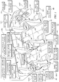
- a collapsible first rear console CR1 in accordance with the present disclosure can be mounted in a passenger compartment 10C on a floor 10F of a vehicle 10 in a position to lie between first and second rear seats SR1, SR2 and along a center aisle A3 of vehicle 10 as shown in Fig. 1 .
- the collapsible first rear console CR1 can be reconfigured as suggested in Figs. 3-5 to change in shape from a relatively tall expanded-use configuration shown in Figs. and 3 to a relatively shorter collapsed compact-storage configuration shown in Fig. 5 .
- first or second rear seats SR1, SR2 in a first rear seating row R1 in passenger compartment 10C it is easy for a passenger sitting on one of the first or second rear seats SR1, SR2 in a first rear seating row R1 in passenger compartment 10C to step over the collapsed first rear console CR1 to access an aft second rear seating row R2 in passenger compartment 10C. It is also within the scope of the present disclosure to locate the collapsible first rear console CR1 in another passenger compartment 10C' of vehicle 10' at the intersection of a center aisle A3' and cross aisle A1' between four swivel seats S1, S2, S3, and S4 as suggested in Fig. 15 .
- a collapsible second rear console CR2 can be collapsed in accordance with the present disclosure to assume a collapsed compact-storage configuration as shown in Fig. 1 .
- the collapsible second rear console CR2 is located along center aisle A3 between third and fourth rear seats SR3, SR4.
- By collapsing the collapsible second rear console CR2 toward floor 10F it is easy for a passenger sitting on one of the third and fourth rear seats SR3, SR4 in the aft second rear seating row R2 to step over the collapsed second rear console CR2 and pass through a space provided between third and fourth rear seats SR3, SR4 to access a rear cargo storage region R3 located behind the third and fourth rear seats SR3, SR4 in passenger compartment 10C.
- the collapsible first rear console CR1 has a variable shape that can be changed by a passenger as suggested in Figs. 3-5 .
- First rear console CR1 is shown in console mode in Fig. 3 and step-over (pass-through) mode in Fig. 4 .
- Second rear console CR2 can be collapsed by a passenger in the same way to assume the step-over (pass-through) mode shown in Fig. 1 .
- Each of the collapsible first and second rear consoles CR1, CR2 can be removed from passenger compartment 10C at the option of passenger in accordance with the present disclosure by decoupling an anchor connector 18 included in each rear console CR1, CR2 from a console anchor 20 mounted on floor 10F as suggested in Figs.
- first and second rear console CR1, CR2 can be converted by a passenger in accordance with the present disclosure from a console mode shown, for example, in Figs. 3 and 6 , to a picnic mode shown, for example, in Fig. 10 .
- collapsible first rear console CR1 comprises a foundation 12, a movable top cap 14, and a cap mover 16 arrange to lie between and interconnect foundation 12 and movable top cap 14.
- Collapsible first rear console CR1 also includes an anchor connector 18 mounted on the underside of foundation 12 and arranged to be coupled to and decoupled from a console anchor 20 mounted on floor 10F.
- a passenger can move the movable top cap 14 relative to foundation 12 from an elevated position shown in Figs. 3 and 6 that is associated with the expanded-use configuration of collapsible first rear console CR1 to a low-profile position shown in Figs. 5 and 8 that is associated with a relatively shorter compact-storage configuration of collapsible first rear console CR1.
- the collapsible first rear console CR1 is changed from a console mode shown in Figs. 3 and 6 to a step-over (pass-through) mode shown in Figs. 5 and 8 .
- the passenger can store items (not shown) in an interior item-storage region 13 formed in first rear console CR1 between foundation 12 and movable top cap 14 by, for example, opening a lid 14L included in movable top cap 14 to access interior item-storage region 13 as suggested in Fig. 9 .
- movable top cap 14 In the collapsed compact-storage configuration (i.e. step-over mode) shown in Fig. 5 , movable top cap 14 has been lowered to a low-profile position that is very close to floor 10F so that a passenger can easily step over the lowered movable top cap 14 to increase pass-through mobility of that passenger between seating rows R1, R2, R3 along center aisle A3 in passenger compartment 10C as suggested in Fig. 1 .
- vehicle passenger compartment 10C also includes a front seating row RF located near a vehicle front 10VF.
- Front seating row RF includes first and second front seats SF1, SF2 and a rigid front console CF located between front seats SF1, SF2. It is within the scope of the present disclosure to replace rigid front console CF with one of the collapsible first or second rear consoles CR1, CR2.
- all of the consoles CF, CR1, and CR2 extend along a center aisle A3 of passenger compartment 10C and lie in spaced-apart relation to one another.
- a first rear cross aisle A1 lies between front seats SF1, SF2 and intersects a forward portion of center aisle A3 as shown in Fig. 1 .
- a second rear cross aisle A2 lies between rear seats SR1, SR2 in first rear seating row R1 and rear seats SR3, SR4 in second rear seating row R2 and intersects a rearward portion of center aisle A3 as also shown in Fig. 1 .
- a vehicle passenger compartment 10C of a vehicle 10 includes a seat-supporting floor 10F, a passenger-seating system 101 lying above floor 10F, and a console system 102 as suggested in Fig. 1 .
- Console system 102 comprises consoles CF, CR1, and CR2 as suggested in Fig. 1 .
- Passenger-seating system 101 includes a front seating row RF and a first rear seating row R1 lying aft of front seating row RF as shown, for example, in Fig. 1 .
- Front seating row RF comprises first and second front seats SF1, SF2 coupled to floor 10F and arranged to lie in laterally spaced-apart relation to one another to define a front console-receiving space 11CF therebetween as shown in Fig. 1 .
- First rear seating row R1 comprises first and second rear seats SR1, SR2 coupled to floor 10F and arranged to lie in laterally spaced-apart relation to one another to define a first rear console-receiving space 11CR1 therebetween as shown in Fig. 1 .
- Console system 102 includes a rigid front console CF and a collapsible first rear console CR1 as suggested in Fig. 1 .
- Rigid front console CF is mounted in a stationary position in the front console-receiving space 11CF to provide a barrier arranged to hinder movement of an occupant using the passenger-seating system 101 along the seat-supporting floor 10F through the front console-receiving space 11CF as shown, for example, in Fig. 1 .
- Collapsible first rear console CR1 is located in the first rear console-receiving space 11CR1 provided between the first and second rear seats SR1, SR2.
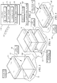
- the collapsible first rear console CR1 includes a foundation 12, a movable top cap 14, and cap mover 16 as shown diagrammatically in Fig. 2 and illustratively in Fig. 6 .
- Cap mover 16 is configured to provide means for selectively moving the movable top cap 14 relative to foundation 12 and the seat-supporting floor 10F under foundation 12 at the option of a console shape-change operator (e.g. passenger) between an elevated position lying in spaced-apart relation to the seat-supporting floor 10F as suggested in Figs.
- a console shape-change operator e.g. passenger
- first rear console CR1 provides a barrier to hinder movement of an occupant using passenger-seating system 101 along the seat-supporting floor 10F through the first rear console-receiving space 11CR1 and a collapsed low-profile position lying along the seat-supporting floor 10F as suggested in Figs.
- Console system 102 further includes a first console anchor 20 mounted in a stationary position on the seat-supporting floor 10F as suggested diagrammatically in Fig. 2 and illustratively in Fig. 11 .
- First console anchor 20 is located in first rear console-receiving space 11CR1 and configured to mate with first rear console CR1 as suggested in Fig. 1 .
- a second console anchor 20 is located in second rear console-receiving space 11CR2 and configured to mate with second rear console CR2 as suggested in Fig. 1 .
- the collapsible first rear console CR1 further includes a releasable anchor connector 18 coupled to foundation 12 as suggested diagrammatically in Fig. 2 and illustratively in Fig. 2 .
- the releasable anchor connector 18 is configured to provide connector means for engaging the first console anchor 20 to locate foundation 12 in a stationary position in the first-rear console-receiving space 11CR1 relative to the seat-supporting floor 10F and for disengaging the first console anchor 20 at the option of an occupant using the passenger-seating system 101 to free foundation 12 to be moved away from the stationary position on seat-supporting floor 10F so that the collapsible first rear console CR1 can be relocated to a new position relative to the seat-supporting floor 10F.
- Passenger-seating system 101 further includes a second rear seating row R2 arranged to lie in spaced-apart relation to the front seating row RF to locate the first rear seating row R1 therebetween as shown, for example, in Fig. 1 .
- Second rear seating row R2 comprises third and fourth rear seats SR3, SR4 coupled to the seat-supporting floor 10F.
- Third and fourth rear seats SR3, SR4 are arranged to lie in laterally spaced-apart relation to one another to define a second rear console-receiving space 11CR2 therebetween.
- Console system 102 further includes a collapsible second rear console CR2 is similar in form and function to first rear consoled CR1 and located in the second rear console-receiving space 11CR2 provided between the third and fourth rear seats SR3, SR4 as shown, for example, in Fig. 1 .
- the collapsible second rear console CR2 is similar in form and function to first rear console CR1 and includes a second foundation 12', a movable second top cap 14', and a second cap mover 16' as shown in Fig. 1 .
- Second cap mover 16' is configured to provide means for selectively moving the movable second top cap 14' relative to second foundation 12' between an elevated position lying in spaced-apart relation to the seat-supporting floor 10F to establish an expanded-use configuration (console mode) of the collapsible second rear console CR2 that provides a barrier to hinder movement of an occupant using passenger-seating system 101 along the seat-supporting floor 10F through the second rear console-receiving space 11CR2 and a collapsed low-profile position lying along the seat-supporting floor 10F as shown in Fig.
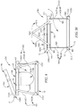
- Cap mover 16 of first rear console CR1 includes a first-end fold linkage 161 having a top mount M1 pivotably coupled to a first end 141 of the top cap 14 and a bottom mount M2 pivotably coupled to a companion first end 121 of the foundation 12 as suggested in Figs. 6-8 .
- First end 121 of foundation 12 is arranged to lie in close proximity to first end 14 of top cap 14 upon movement of top cap 14 to the collapsed low-profile position as shown in Fig. 8 .
- Top and bottom mounts M1, M2 are separated by a first distance D1 when top cap 14 occupies the elevated position as shown in Fig. 6 and a relatively shorter second distance D2 when top cap 14 occupies the collapsed low-profile position as shown in Fig. 8 .
- Cap mover 16 further include a first linkage stabilizer 161S having a free end 161F and an opposite pivot end 161P as shown in Figs. 6 and 7 .
- Pivot end 161P is mounted on the first end 141 of top cap 14 for pivotable movement about a first horizontal pivot axis between a first linkage-stabilizing position in which free end 161F engages first end 121 of foundation 12 as shown in Fig. 6 to rigidify first-end fold linkage 161 and retain top cap 14 in the elevated position and other positions in which free end 161F disengages first end 121 of foundation 12 as shown in Figs. 7 and 8 to unrigidify first-end fold linkage 161 to allow downward movement of top cap 14 from the elevated position shown in Fig.
- Free end 161F is arranged to extend into an outwardly opening end-receiving channel 121C formed in a perimeter end edge of first end 121 of foundation 12 when top cap 14 occupies the elevated position as suggested in Figs. 6 and 9 (channel 121C is shown best in Figs. 7 and 8 when empty).
- Free end 161F of first linkage stabilizer 161S is arranged to lie in spaced-apart relation to foundation 12 in one of the other positions to locate top cap 14 therebetween and provide a carry handle 16H located above top cap 14 to establish a picnic mode as suggested in Fig. 10 .
- the picnic mode is used, for example, when first rear console CR1 is removed from vehicle 10.
- Free end 161F of first linkage stabilizer 161S is arranged to extend into an end-receiver channel 161C formed in top cap 14 when top cap 14 occupies the collapsed low-profile position as shown in Fig. 8 .
- First-end fold linkage 161 includes a top link 161T and a bottom link 161B as shown in Fig. 6-10 .
- Top link 161T includes the top mount M1 at one end and a pivot mount M3 in an opposite end as suggested in Fig. 10 .
- Bottom link 161B includes the bottom mount M2 at one end and a pivot mount M3 at an opposite end as also suggested in Fig. 10 .
- the pivot mounts M3, M3 are coupled to one another at a horizontal link-pivot axis as suggested in Fig.
- top and bottom links 161T, 161B for pivotable movement relative to one another about the horizontal link-pivot axis to allow movement of the top mount M1 relative to bottom mount M2 during movement of top cap 14 relative to foundation 12 as shown, for example, in Fig. 6-8 .
- Top and bottom links 161T, 161B are arranged to extend along a line and lie in in-line relation to one another when top cap 14 occupies the elevated position as suggested in Figs. 6 , 9, and 10 .
- Top and bottom links 161T, 161B are arranged to establish a first V-shape and cooperate to form a first acute angle therebetween having a first measure when top cap 14 is located in an intermediate position part way between the elevated and collapsed low-profile positions as suggested in Fig. 7 .
- Top and bottom links are also arranged to establish a second V-shape and cooperate to form a second acute angle therebetween having a relatively smaller second measure when top cap 14 occupies the collapsed low-profile position as suggested in Fig. 8 .
- Top link 161T has a first length as suggested in Fig. 10 .
- Bottom link 161B also has a length that is the same as the first length as suggested in Fig. 10 .
- First linkage stabilizer 161S has a relatively longer second length as suggested in Figs. 6 and 10 .
- First linkage stabilizer 161S has a length that is longer than a combined length of top and bottom links 161T, 161B when top and bottom links 161T, 161B are arranged to extend along a line and lie in an in-line relation to one another when top cap 14 occupies the elevated position as shown in Fig. 6 .
- Foundation 12 has a first end 121 and an opposite second end 122 while top cap 14 has a first end 141 and an opposite second end 142 as shown in Fig. 10 .
- Pivot end 161P of first linkage stabilizer 161S is arranged to lie on first end 141 of top cap 14 in a location between top mount M1 of first-end fold linkage 161 and second end 142 of top cap 14 as shown in Fig. 6 .
- Bottom mount M2 of first-end fold linkage 161 is arranged to lie on first end 121 of foundation 12 in a location between free end 161F of first linkage stabilizer 161S and second end 122 of foundation 12 when free end 161F of first linkage stabilizer 161S engages first end 121 of foundation 12 and top cap 14 occupies the elevated position as also shown in Fig. 6 .
- First-end fold linkage 161 extends coextensively along a vertical line as shown in Figs. 6 and 10 .
- First linkage stabilizer 161S extends along a positively sloping line when top cap 14 occupies the elevated position and first rear console RC1 is in console mode as shown in Fig. 6 .
- Cap mover 16 further includes a second-end fold linkage 162 having a top mount M1 pivotably coupled to a second end 142 of top cap 14 and a bottom mount M2 pivotably coupled to a companion second end 122 of foundation 12 as shown in Fig. 6 .
- Foundation 12 is arranged to lie in close proximity to second end 142 of top cap 14 upon movement of top cap 14 to the collapsed low-profile position as shown in Fig. 8 .
- Top and bottom mounts M1, M2 are separated by a first distance D1 when top cap 14 occupies the elevated position as suggested in Fig. 6 and a relatively shorter second distance D2 when top cap 14 occupies collapsed low-profile position as suggested in Fig. 8 .
- Cap mover 16 further include a second linkage stabilizer 162S having a free end 162F and an opposite pivot end 162P.
- Pivot end 162P is mounted on second end 142 of top cap 14 for pivotable movement about a second horizontal pivot axis between a second linkage-stabilizing position in which free end 162F engages second end 122 of foundation 12 to rigidify second-end fold linkage 162 and retain top cap 14 in elevated position as suggested in Fig. 6 and other positions in which free end 162F disengages second end 122 of foundation 12 to unrigidify second-end fold linkage 162 to allow downward movement of top cap 14 from elevated position shown in Fig. 6 to collapsed low-profile position shown in Fig. 8 .
- Free end 162F is arranged to extend into an outwardly opening end-receiving channel 122C formed in a perimeter end edge of second end 122 of foundation 12 when top cap 14 occupies the elevated positon as shown in Figs. 6 and 9 .
- Free end 162F of second linkage stabilizer 162S is arranged to lie in spaced-apart relation to foundation 12 in one of other positions to locate top cap 14 therebetween and cooperate with free end 161F of first linkage stabilizer 161S to provide a carry handle 16H located above top cap 14 as shown in Fig. 10 .
- Free end 162F of second linkage stabilizer 162S is arranged to extend into an end-receiver channel 162C formed in top cap 14 when top cap 14 occupies the collapsed low-profile position.
- Anchor connector 18 of first rear console CR1 can be mated with console anchor 20 on floor 10F as suggested in Figs. 11-14 to retain first rear console CR1 in a stationary position on floor 10F.
- Second rear console CR1 can be anchored to floor 10F in the same way.
- Each console anchor 20 comprises a front mount 20F coupled to floor 10F and rear mount 20R coupled to floor 10F and arranged to lie in spaced-apart relation to front mount 20F as shown, for example, in Fig. 11 .
- Anchor connector 18 is configured to provide means for releasably mating with the companion front and rear mounts 20F, 20R as suggested diagrammatically in Fig. 11 and illustratively in Figs. 12-14 .
- Each mount 20F, 20R could be a U-hook as shown in Fig. 11 or another suitable structure coupled to floor 10F or any other nearby feature.
- a pivot base 181 of anchor connector 18 is mated with rear mount 20R of console anchor 20 to cause a releasable mount grip 182 of anchor connector to overlie front mount 20F of console anchor 20.
- Releasable mount grip 182 comprises a clamp base 183, a movable clamp 185 mounted for movement relative to clamp base 183 to open and close a mount-receiver space 184 provided therebetween, and a clamp-biasing spring 186 acting between clamp base 183 and movable clamp 185.
- a passenger or other operator applies a pulling force Fp to movable clamp 185 to move clamp 185 away from clamp base 183 to open mount-receiver space 184 and then pivots foundation 12 in a clockwise direction about a horizontal pivot axis 12A associated with rear mount 20R while continuing to apply pulling force Fp until a horizontally extending bar 20FB of front mount 20F lies in mount-receiver space 184.
- the passenger or operator releases movable clamp 185 to allow a spring force FS to move movable clamp 185 toward clamp base 183 and trap horizontally extending bar 20FB of front mount 20F in mount-receiving space 184 between clamp base 183 and movable clamp 185.
- This clamping action causes the spring-loaded clamp 185 to contain front mount 20F and secure foundation 12 of the collapsible first rear console CR1 in a stationary position on floor 10F as suggested in Figs. 1 and 14 .
- Top cap 14 includes a lid frame 144 and a lid 146 mounted on lid frame 144 to be opened and closed as suggested in Figs. 9 and 10 by a passenger or operator to control access to an interior item-storage region 13 provided in first rear console CR1 as suggested in Figs. 3 , 9, and 10 when that console CR1 is placed in console mode.
- lid 146 includes a closure 146C and a closure hinge 146H configured to provide means for supporting closure 146C for pivotable movement about a horizontal pivot axis 146A between an opened position suggested in Fig. 9 and a closed position suggested in Fig. 10 .
- Each of the rear consoles CR1, CR2 in accordance with the present disclosure are collapsible when not in use to allow walking between seats.
- Lid 146 of top cap 14 is hinged to keep items (not shown) in interior item-storage region 13 of a rear console CR1 and CR2.
- Covered pop-off pass-through and side-hooks 19 are provided as shown, for example, in Fig. 9 to allow plastic bags 19B to be attached for garbage collection.
- Each of linkage stabilizers 161S, 162S is a hinged bar that functions in accordance with the present disclosure to provide: (1) strong support for other console components when installed to establish the console mode of the console, (2) carrying handle(s) 16H in the picnic mode of the console, (3) and snap into top cap 14 when the console is in the step-over (pass-through) mode of the console.
- Sides of each console CR1, CR2 are made, for example, of thin plastic or canvas or other similar pliable but sturdy material and can be snap-connected or otherwise coupled temporarily to linkage stabilizers 161S, 162S in console mode to rigidify the console.
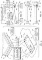
- a passenger compartment 10C' in a vehicle 10' is shown in Fig. 15 and comprises a floor 10F' and four swivel seats S1, S2, S3, and S4.
- Seats S1, S2 lie in a first seating row and seats S3, S4 lie in a second row.
- First seat S1 can swivel about axis of rotation AS1 as suggest in Fig. 15 .
- Second seat S2 can swivel about axis of rotation AS2.
- Third seat S3 can swivel about axis of rotation AS3.
- Fourth seat S4 can swivel about axis of rotation AS4.
- first rear console CR1 is retained in a stationary position on floor 10F' to lie at an intersection of the cross and center aisles A1', A3'. It is within the scope of the present disclosure to retain first rear console CR1 in another position on floor 10F' when the rotational orientation of seats S1-S4 is changed.
Landscapes
- Engineering & Computer Science (AREA)
- Mechanical Engineering (AREA)
- Transportation (AREA)
- Aviation & Aerospace Engineering (AREA)
- Physics & Mathematics (AREA)
- Thermal Sciences (AREA)
- Vehicle Step Arrangements And Article Storage (AREA)
Claims (14)
- Fahrzeuginnenraum, umfassendeinen Sitztrageboden (10F), ein Fahrgastsitzsystem, das über dem Sitztrageboden (10F) liegt und eine vordere Sitzreihe (RF), die einen ersten und einen zweiten Vordersitz (SF1, SF2) umfasst, die an den Sitztrageboden (10F) gekoppelt und so angeordnet sind, dass sie in seitlich beabstandeter Beziehung zueinander liegen, um dazwischen einen vorderen Konsolenaufnahmeraum zu definieren, und eine erste hintere Sitzreihe (R1) aufweist, die hinter der vorderen Sitzreihe (RF) liegt und einen ersten und einen zweiten Rücksitz (SR1, SR2) umfasst, die an den Sitztrageboden (10F) gekoppelt und so angeordnet sind, dass sie in seitlich beabstandeter Beziehung zueinander liegen, um dazwischen einen ersten hinteren Konsolenaufnahmeraum zu definieren, undein Konsolensystem, das eine starre vordere Konsole (CF), die in einer feststehenden Position in dem vorderen Konsolenaufnahmeraum montiert ist, um eine Sperre bereitzustellen, die dazu angeordnet ist, eine Bewegung eines das Fahrgastsitzsystem benutzenden Insassen entlang des Sitztragebodens (10F) durch den vorderen Konsolenaufnahmeraum zu hemmen, und eine zusammenklappbare erste hintere Konsole (CR1) aufweist, die in dem ersten hinteren Konsolenaufnahmeraum, der zwischen dem ersten und dem zweiten Rücksitz (SR1, SR2) vorgesehen ist, angeordnet ist, wobei die zusammenklappbare erste hintere Konsole (CR1) ein Fundament (12), eine bewegliche obere Kappe (14) und Kappenbewegungsmittel (16) aufweist, um die bewegliche obere Kappe (14) bezüglich des Fundaments (12) und des Sitztragebodens (10F) unter dem Fundament (12) nach Wahl einer die Konsolenform ändernden Betriebsperson gezielt zwischen einer angehobenen Position, die in beabstandeter Beziehung zu dem Sitztrageboden (10F) liegt, um eine expandierte Gebrauchskonfiguration der zusammenklappbaren ersten hinteren Konsole (CR1) herzustellen, die eine Sperre bereitstellt, um eine Bewegung eines das Fahrgastsitzsystem benutzenden Insassen entlang des Sitztragebodens (10F) durch den ersten hinteren Konsolenaufnahmeraum zu hemmen, und einer zusammengeklappten Position mit niedrigem Profil zu bewegen, die entlang des Sitztragebodens (10F) liegt, um eine zusammengeklappte Konfiguration zur kompakten Lagerung der zusammenklappbaren ersten hinteren Konsole (CR1) herzustellen, um einen Insassentransitdurchgang zwischen dem ersten und dem zweiten Rücksitz (SR1, SR2) bereitzustellen, um eine freie Durchgangsbewegung eines das Fahrgastsitzsystem benutzenden Insassen durch den ersten hinteren Konsolenaufnahmeraum entlang des Sitztragebodens (10F) über der oberen Kappe (14) zu gestatten,dadurch gekennzeichnet, dassdas Kappenbewegungsmittel (16) ein am ersten Ende angeordnetes Klappgestänge (161) aufweist, das eine obere Halterung (M1), die schwenkbar an ein erstes Ende (141) der oberen Kappe (14) gekoppelt ist, und eine untere Halterung (M2) hat, die an ein erstes Gegen-Ende (121) des Fundaments (12) gekoppelt ist, das so angeordnet ist, dass es bei Bewegung der oberen Kappe (14) in die zusammengeklappte Position mit niedrigem Profil in nächster Nähe des ersten Endes (141) der oberen Kappe (14) liegt,die obere und die untere Halterung (M1, M2) über einen ersten Abstand (D1) getrennt sind, wenn die obere Kappe (14) die angehobene Position einnimmt, und über einen relativ kürzeren zweiten Abstand (D2), wenn die obere Kappe (14) die zusammengeklappte Position mit niedrigem Profil einnimmt, unddie Kappenbewegungsmittel (16) ferner einen ersten Gestängestabilisator (161S) mit einem freien Ende (161F) und einem gegenüberliegenden Schwenkende (161P) aufweisen, das an dem ersten Ende (141) der oberen Kappe (14) zur schwenkenden Bewegung um eine erste horizontale Schwenkachse zwischen einer ersten Gestängestabilisierposition, in der das freie Ende (161F) das erste Ende (121) des Fundaments (12) in Eingriff nimmt, um das am ersten Ende angeordnete Klappgestänge (161) zu versteifen und die obere Kappe (14) in der angehobenen Position zu halten, und anderen Positionen montiert ist, in denen das freie Ende (161F) aus dem ersten Ende (121) des Fundaments (12) ausrückt, damit das am ersten Ende angeordnete Klappgestänge (161) nicht mehr steif ist, um eine Bewegung der oberen Kappe (14) von der angehobenen Position nach unten in die zusammengeklappte Position mit niedrigem Profil zu gestatten.
- Fahrzeuginnenraum nach Anspruch 1, wobei das Fahrgastsitzsystem ferner eine zweite hintere Sitzreihe (R2) aufweist, die so angeordnet ist, dass sie in beabstandeter Beziehung zu der vorderen Sitzreihe (RF) liegt, so dass die erste hintere Sitzreihe (R1) dazwischen angeordnet ist, wobei die zweite hintere Sitzreihe (R2) einen dritten und einen vierten Rücksitz (SR3, SR4) umfasst, die an den Sitztrageboden (10F) gekoppelt und so angeordnet sind, dass sie in seitlich beabstandeter Beziehung zueinander liegen, um dazwischen einen zweiten hinteren Konsolenaufnahmeraum zu definieren, und wobei das Konsolensystem ferner eine zusammenklappbare zweite hintere Konsole (CR2) aufweist, die in dem zweiten hinteren Konsolenaufnahmeraum, der zwischen dem dritten und dem vierten Rücksitz (SR3, SR4) vorgesehen ist, angeordnet ist, wobei die zusammenklappbare zweite hintere Konsole (CR2) ein zweites Fundament, eine zweite bewegliche obere Kappe und Mittel aufweist, um die zweite bewegliche obere Kappe bezüglich des zweiten Fundaments gezielt zwischen einer angehobenen Position, die in beabstandeter Beziehung zu dem Sitztrageboden (10F) liegt, um eine expandierte Gebrauchskonfiguration der zusammenklappbaren zweiten hinteren Konsole (CR2) herzustellen, die eine Sperre bereitstellt, um eine Bewegung eines das Fahrgastsitzsystem benutzenden Insassen entlang des Sitztragebodens (10F) durch den zweiten hinteren Konsolenaufnahmeraum zu hemmen, und einer zusammengeklappten Position mit niedrigem Profil zu bewegen, die entlang des Sitztragebodens (10F) liegt, um eine zusammengeklappte Konfiguration zur kompakten Lagerung der zusammenklappbaren zweiten hinteren Konsole (CR2) herzustellen, um einen Insassentransitdurchgang zwischen dem dritten und dem vierten Rücksitz (SR3, SR4) bereitzustellen, um eine freie Durchgangsbewegung eines das Fahrgastsitzsystem benutzenden Insassen durch den zweiten hinteren Konsolenaufnahmeraum entlang des Sitztragebodens (10F) über der zweiten oberen Kappe zu gestatten.
- Fahrzeuginnenraum nach Anspruch 1 oder 2, wobei das freie Ende (161F) des ersten Gestängestabilisators (161S) so angeordnet ist, dass es in beabstandeter Beziehung zu dem Fundament (12) in einer der anderen Positionen liegt, um die obere Kappe (14) dazwischen anzuordnen und einen über der oberen Kappe (14) angeordneten Tragegriff bereitzustellen.
- Fahrzeuginnenraum nach Anspruch 1 oder 2, wobei das freie Ende (161F) des ersten Gestängestabilisators (161S) so angeordnet ist, dass es sich in einen in der oberen Kappe (14) ausgebildeten Endaufnehmerkanal (161C) erstreckt, wenn die obere Kappe (14) die zusammengeklappte Position mit niedrigem Profil einnimmt.
- Fahrzeuginnenraum nach Anspruch 1 oder 2, wobei das am ersten Ende angeordnete Klappgestänge (161) ein oberes Verbindungsglied (161T) und ein unteres Verbindungsglied (161B) aufweist, wobei das obere Verbindungsglied (161T) an einem Ende die obere Halterung (M1) und an einem gegenüberliegenden Ende eine Schwenkhalterung (M3) aufweist, das untere Verbindungsglied an einem Ende die untere Halterung (M2) und an einem gegenüberliegenden Ende eine Schwenkhalterung (M3) aufweist und die Schwenkhalterungen aneinandergekoppelt sind, um das obere und das untere Verbindungsglied (161T, 161B) für eine Schwenkbewegung bezüglich einander um eine horizontale Verbindungsgliedschwenkachse zu stützen, um eine Bewegung der oberen Halterung (M1) bezüglich der unteren Halterung (M2) während einer Bewegung der oberen Kappe (14) bezüglich des Fundaments (12) zu gestatten.
- Fahrzeuginnenraum nach Anspruch 5, wobei das obere und das untere Verbindungsglied (161T, 161B) so angeordnet sind, dass sie sich entlang einer Linie erstrecken und bezüglich einander auf einer Linie liegen, wenn die obere Kappe (14) die angehobene Position einnimmt, um eine erste V-Form herzustellen und zusammenzuwirken, um einen ersten spitzen Winkel mit einem ersten Maß dazwischen zu bilden, wenn die obere Kappe (14) auf halbem Wege zwischen der angehobenen und der zusammengeklappten Position mit niedrigem Profil angeordnet ist, und um eine zweite V-Form herzustellen und zusammenzuwirken, um einen zweiten spitzen Winkel mit einem relativ kleineren zweiten Maß dazwischen zu bilden, wenn die obere Kappe (14) die zusammengeklappte Position mit niedrigem Profil einnimmt.
- Fahrzeuginnenraum nach Anspruch 1 oder 2, wobei die obere Kappe (14) und die Fundamente jeweils ein zweites Ende (122, 142) gegenüber dem ersten Ende aufweisen, das Schwenkende (161P) des ersten Gestängestabilisators (161S) so angeordnet ist, dass es auf dem ersten Ende (141) der oberen Kappe (14) an einer Stelle zwischen der oberen Halterung (M1) des am ersten Ende angeordneten Klappgestänges (161) und dem zweiten Ende (142) der oberen Kappe (14) liegt, und die untere Halterung (M2) des ersten Gestängestabilisators (161) so angeordnet ist, dass es auf dem ersten Ende (121) des Fundaments (12) an einer Stelle zwischen dem freien Ende (161F) des ersten Gestängestabilisators (161S) und dem zweiten Ende (122) des Fundaments (12) liegt, wenn das freie Ende (161F) des ersten Gestängestabilisators (161S) das erste Ende (121) des Fundaments (12) in Eingriff nimmt und die obere Kappe (14) die angehobene Position einnimmt.
- Innenraum für Fahrzeugpositionierer nach Anspruch 7, wobei sich das am ersten Ende angeordnete Klappgestänge (161) koextensiv entlang einer vertikalen Linie erstreckt und sich der erste Gestängestabilisator (161S) entlang einer sich positiv neigenden Linie erstreckt, wenn die obere Kappe (14) die angehobene Position einnimmt.
- Fahrzeuginnenraum nach Anspruch 1 oder 2, wobei das Kappenbewegungsmittel (16) ferner ein am zweiten Ende angeordnetes Klappgestänge (162) aufweist, das eine obere Halterung (M1), die schwenkbar an ein zweites Ende (142) der oberen Kappe (14) gekoppelt ist, und eine untere Halterung (M2) hat, die an ein zweites Gegen-Ende (122) des Fundaments (12) gekoppelt ist, das so angeordnet ist, dass es bei Bewegung der oberen Kappe (14) in die zusammengeklappte Position mit niedrigem Profil in nächster Nähe des zweiten Endes (142) der oberen Kappe (14) liegt, die obere und die untere Halterung (M1, M2) über einen ersten Abstand (D1) getrennt sind, wenn die obere Kappe (14) die angehobene Position einnimmt, und über einen relativ kürzeren zweiten Abstand (D2), wenn die obere Kappe (14) die zusammengeklappte Position mit niedrigem Profil einnimmt, und die Kappenbewegungsmittel (16) ferner einen zweiten Gestängestabilisator (162S) mit einem freien Ende (162F) und einem gegenüberliegenden Schwenkende (162P) aufweisen, das an dem zweiten Ende (142) der oberen Kappe (14) zur schwenkenden Bewegung um eine zweite horizontale Schwenkachse zwischen einer zweiten Gestängestabilisierposition, in der das freie Ende (162F) das zweite Ende (122) des Fundaments (12) in Eingriff nimmt, um das am zweiten Ende angeordnete Klappgestänge (162) zu versteifen und die obere Kappe (14) in der angehobenen Position zu halten, und anderen Positionen montiert ist, in denen das freie Ende (162F) aus dem zweiten Ende (122) des Fundaments (12) ausrückt, damit das am zweiten Ende angeordnete Klappgestänge (162) nicht mehr steif ist, um eine Bewegung der oberen Kappe (14) von der angehobenen Position nach unten in die zusammengeklappte Position mit niedrigem Profil zu gestatten.
- Fahrzeuginnenraum nach einem der Ansprüche 1 bis 9, wobei das Konsolensystem ferner einen ersten Konsolenanker (20) aufweist, der in einer stationären Position auf dem Sitztrageboden (10F) montiert ist, und die zusammenklappbare erste hintere Konsole (CR1) ferner einen freigebbaren Ankerverbinder aufweist, der an das Fundament (12) gekoppelt und dazu ausgestaltet ist, Verbindermittel bereitzustellen, um den ersten Konsolenanker (20) in Eingriff zu nehmen, um das Fundament (12) in einer stationären Position in dem ersten hinteren Konsolenaufnahmeraum bezüglich des Sitztragebodens (10F) anzuordnen, und um nach Wahl des das Fahrgastsitzsystem benutzenden Insassen aus dem ersten Konsolenanker (20) auszurücken, so dass das Fundament (12) frei aus der stationären Position auf dem Sitztrageboden (10F) bewegt werden kann, so dass die zusammenklappbare erste hintere Konsole (CR1) in einer neuen Position bezüglich des Sitztragebodens (10F) angeordnet werden kann.
- Fahrzeuginnenraum nach Anspruch 10, wobei der erste Konsolenanker (20) eine an den Boden gekoppelte vordere Halterung (20F) und eine hintere Halterung (20R) aufweist, die an den Boden gekoppelt und dazu angeordnet ist, in beabstandeter Beziehung zu der vorderen Halterung (20F) zu liegen, und der Ankerverbinder der ersten hinteren Konsole (CR1) die vordere und die hintere Halterung in Eingriff nimmt, um das Fundament (12) in der stationären Position in dem ersten hinteren Konsolenaufnahmeraum anzuordnen und zu halten.
- Fahrzeuginnenraum nach Anspruch 10, wobei der Ankerverbinder eine Schwenkbasis (181) aufweist, die an das Fundament (12) gekoppelt ist, um sich damit zu bewegen, und für eine vorübergehende schwenkbare Bewegung um eine horizontale Schwenkachse während des Eingriffs des Ankerverbinders mit der vorderen Halterung (20F) freigebbar an der hinteren Halterung (20R) montiert ist, sowie einen freigebbaren Halterungsgriff (182), der an das Fundament (12) gekoppelt ist, um sich damit zu bewegen, und dazu ausgeführt ist, die vordere Halterung (20F) während des Eingriffs des Ankerverbinders mit der hinteren und der vorderen Halterung in Eingriff zu nehmen.
- Fahrzeuginnenraum nach Anspruch 12, wobei der freigebbare Halterungsgriff (182) eine Klemmenbasis (183), die an das Fundament (12) gekoppelt ist, um sich damit zu bewegen, eine bewegliche Klemme (185), die zur Bewegung bezüglich der Klemmenbasis (183) montiert ist, um einen zwischen der Klemmenbasis (183) und der beweglichen Klemme (185) vorgesehenen Halterungsempfängerraum (184) zu öffnen und zu schließen, und eine Klemmenvorspannfeder (186) aufweist, die zwischen der Klemmenbasis (183) und der beweglichen Klemme (185) wirkt, um ein Mittel zum Bewegen der beweglichen Klemme (185) zu der Klemmenbasis (183) hin bereitzustellen, um einen Stangenabschnitt der in dem Halterungsempfängerraum (184) angeordneten vorderen Halterung (20F) zu erfassen, um das Fundament (12) in der stationären Position auf dem Sitztrageboden (10F) zu halten, nachdem die Schwenkbasis (181) an einem Stangenabschnitt der hinteren Halterung (20R) geschwenkt hat, um den freigebbaren Halterungsgriff nach unten zu der vorderen Halterung (20F) hin zu bewegen, und die bewegliche Klemme (185) gegen eine von der Klemmenvorspannfeder (186) bereitgestellte Vorspannkraft von der Klemmenbasis (183) weg bewegt worden ist, um den Halterungsempfängerraum (184) zu öffnen, um den Stangenabschnitt der vorderen Halterung (20F) in den Halterungsempfängerraum (184) zu platzieren.
- Fahrzeuginnenraum nach einem der Ansprüche 1 bis 13, wobei die obere Kappe (14) einen Deckelrahmen (144) und einen Deckel (146) aufweist, der zur Bewegung bezüglich des Deckelrahmens (144) montiert ist, um eine Öffnung in einen inneren Artikellagerbereich (13), der in der zusammenklappbaren ersten hinteren Konsole (CR1) ausgebildet ist, zu öffnen und zu schließen, wobei das Kappenbewegungsmittel (16) ein am ersten Ende angeordnetes Klappgestänge (161) aufweist, das eine obere Halterung (M1), die schwenkbar an ein erstes Ende des Deckelrahmens (144) der oberen Kappe (14) gekoppelt ist, und eine untere Halterung (M2) aufweist, die schwenkbar an ein erstes Gegen-Ende (121) des Fundaments (12) gekoppelt ist, das so angeordnet ist, dass es bei Bewegung der oberen Kappe (14) in die zusammengeklappte Position mit niedrigem Profil in nächster Nähe des ersten Endes (141) der oberen Kappe (14) liegt, und das Kappenbewegungsmittel (16) ferner einen ersten Gestängestabilisator (161S) mit einem freien Ende (161F) und einem gegenüberliegenden Schwenkende (161P) aufweist, das an dem ersten Ende des Deckelrahmens (144) der oberen Kappe (14) zur schwenkenden Bewegung um eine erste horizontale Schwenkachse zwischen einer Gestängestabilisierposition, in der das freie Ende (161F) das erste Ende (121) des Fundaments (12) in Eingriff nimmt, um das am ersten Ende angeordnete Klappgestänge (161) zu versteifen und die obere Kappe (14) in der angehobenen Position zu halten, und anderen Positionen montiert ist, in denen das freie Ende (161F) aus dem ersten Ende (121) des Fundaments (12) ausrückt, damit das am ersten Ende angeordnete Klappgestänge (161) nicht mehr steif ist, um eine Bewegung der oberen Kappe (14) von der angehobenen Position nach unten in die zusammengeklappte Position mit niedrigem Profil zu gestatten.
Applications Claiming Priority (1)
| Application Number | Priority Date | Filing Date | Title |
|---|---|---|---|
| US15/874,920 US10525893B2 (en) | 2018-01-19 | 2018-01-19 | Middle console for vehicle passenger compartment |
Publications (2)
| Publication Number | Publication Date |
|---|---|
| EP3514008A1 EP3514008A1 (de) | 2019-07-24 |
| EP3514008B1 true EP3514008B1 (de) | 2021-10-27 |
Family
ID=65036632
Family Applications (1)
| Application Number | Title | Priority Date | Filing Date |
|---|---|---|---|
| EP19152214.3A Active EP3514008B1 (de) | 2018-01-19 | 2019-01-17 | Mittelkonsole für einen fahrzeuginsassenraum |
Country Status (3)
| Country | Link |
|---|---|
| US (1) | US10525893B2 (de) |
| EP (1) | EP3514008B1 (de) |
| CN (1) | CN110053562B (de) |
Families Citing this family (16)
| Publication number | Priority date | Publication date | Assignee | Title |
|---|---|---|---|---|
| FR3065680B1 (fr) * | 2017-04-27 | 2021-01-08 | Faurecia Interieur Ind | Habitacle et vehicule autonome ou semi-autonome associe |
| US20190111849A1 (en) * | 2017-10-16 | 2019-04-18 | Matthew Thomas Besley | Open Space Organizer Apparatus and System |
| US10814746B2 (en) * | 2018-12-17 | 2020-10-27 | Honda Motor Co., Ltd. | Rotatable seat configuration with multi-use table |
| DE102019218721A1 (de) * | 2019-12-02 | 2021-06-02 | Brose Fahrzeugteile SE & Co. Kommanditgesellschaft, Coburg | Konsolenelement für ein Fahrzeug |
| US11173820B2 (en) * | 2020-01-14 | 2021-11-16 | Honda Motor Co., Ltd. | Headrest, vehicle seat and vehicle |
| JP2021155002A (ja) * | 2020-03-30 | 2021-10-07 | 本田技研工業株式会社 | 車両 |
| US11279269B1 (en) | 2020-09-23 | 2022-03-22 | Ford Global Technologies, Llc | Armrest assembly moveable between raised and lowered positions |
| US11904732B2 (en) | 2020-11-09 | 2024-02-20 | Ford Global Technologies, Llc | Vehicular system capable of adjusting a passenger compartment from a first arrangement to a child care arrangement |
| US11772520B2 (en) | 2020-11-09 | 2023-10-03 | Ford Global Technologies, Llc | Remote notification and adjustment of a passenger compartment arrangement |
| US12257932B2 (en) | 2020-11-09 | 2025-03-25 | Ford Global Technologies, Llc | Exterior imager utilized in adjusting a passenger compartment arrangement |
| US12077068B2 (en) | 2020-11-09 | 2024-09-03 | Ford Global Technologies, Llc | Authorization-based adjustment of passenger compartment arrangement |
| US11731535B2 (en) | 2020-11-09 | 2023-08-22 | Ford Global Technologies, Llc | Vehicular system capable of adjusting a passenger compartment from a child care arrangement to a second arrangement |
| US11772519B2 (en) | 2020-11-09 | 2023-10-03 | Ford Global Technologies, Llc | Vehicular system capable of adjusting a passenger compartment from a first arrangement to a child seat arrangement |
| US11772517B2 (en) | 2020-11-09 | 2023-10-03 | Ford Global Technologies, Llc | Vehicular system capable of adjusting a passenger compartment from a child seat arrangement to a second arrangement |
| KR20230070788A (ko) * | 2021-11-15 | 2023-05-23 | 현대자동차주식회사 | 자율주행 차량의 시트 자동 배열방법 및 장치 |
| US12351132B2 (en) * | 2022-10-24 | 2025-07-08 | Faurecia Interior Systems, Inc. | Collapsible vehicle interior console |
Family Cites Families (46)
| Publication number | Priority date | Publication date | Assignee | Title |
|---|---|---|---|---|
| US3136461A (en) * | 1962-08-01 | 1964-06-09 | Jr David F Gregg | Automobile service bar |
| US3356409A (en) * | 1965-09-09 | 1967-12-05 | Ford Motor Co | Sliding console |
| US3572818A (en) * | 1969-07-22 | 1971-03-30 | Allied Chem | Vehicle seat construction and arrangement |
| DE4340675A1 (de) | 1993-11-30 | 1995-06-01 | Bayerische Motoren Werke Ag | Kofferraumboden für Kraftfahrzeuge |
| DE4432369C2 (de) | 1994-09-12 | 2000-05-31 | Thierry Philippart | Zusammenklappbarer Korb für Pkw-Kofferräume und Lkw-Ladeflächen eingepaßt in die Auflagefläche des Wagens |
| DE19611892C1 (de) * | 1996-03-26 | 1997-09-11 | Daimler Benz Ag | Mittelkonsole für einen Personenkraftwagen |
| DE19650767A1 (de) | 1996-12-06 | 1998-07-30 | Baumeister & Ostler Gmbh Co | Aufbewahrungssystem zur Verwendung in Kofferräumen von Personenkraftwagen |
| DE19711379C1 (de) * | 1997-03-19 | 1998-05-07 | Daimler Benz Ag | Fahrzeug |
| CA2245311C (en) * | 1997-08-19 | 2006-10-24 | Atoma International Inc. | Multi-position sliding center console with adjustable table top |
| US6026646A (en) | 1998-08-24 | 2000-02-22 | Prince Corporation | Thermal storage system for a vehicle |
| US6203088B1 (en) * | 1999-01-19 | 2001-03-20 | Johnson Controls Technology Company' | Sliding console system |
| DE10029612A1 (de) * | 1999-07-14 | 2001-01-18 | Volkswagen Ag | Anzeige- und/oder Bedieneinrichtung für mindestens eine elektrische Einrichtung in Kraftfahrzeugen |
| WO2001036226A2 (en) | 1999-11-16 | 2001-05-25 | Lear Corporation | Anchorage system for automotive vehicle seats |
| US6264261B1 (en) * | 1999-12-20 | 2001-07-24 | Ford Global Tech., Inc. | Vehicle console |
| US6367857B2 (en) * | 2000-01-07 | 2002-04-09 | Daimlerchrysler Corporation | Removable console assembly for a motor vehicle |
| US6726267B2 (en) * | 2000-04-25 | 2004-04-27 | Johnson Controls Technology Company | Console assembly |
| US6428072B1 (en) * | 2000-09-08 | 2002-08-06 | Auto Additions, Inc. | Vehicle equipment console |
| US6752444B2 (en) * | 2001-05-28 | 2004-06-22 | Mitsubishi Denki Kabushiki Kaisha | Device installation apparatus for moving body |
| US6921118B2 (en) * | 2002-04-22 | 2005-07-26 | Johnson Controls Technology Company | Sliding and nesting console system |
| US20030234550A1 (en) * | 2002-06-24 | 2003-12-25 | Brooks Vincent L. | Traveling console |
| JP3768467B2 (ja) * | 2002-09-19 | 2006-04-19 | 本田技研工業株式会社 | 車両用シート構造 |
| FR2850919A1 (fr) * | 2003-02-07 | 2004-08-13 | Renault Sa | Console pour habitacle de vehicule |
| DE10321837B4 (de) | 2003-05-15 | 2014-03-27 | Volkswagen Ag | Mittelkonsole für ein Fahrzeug |
| US20050146171A1 (en) * | 2003-12-24 | 2005-07-07 | Lear Corporation | Two piece console and seat assembly |
| DE202004003844U1 (de) | 2004-03-10 | 2005-07-14 | Grammer Automotive Gmbh | Mittelkonsole für einen Kraftwagen |
| US7561706B2 (en) * | 2004-05-04 | 2009-07-14 | Bose Corporation | Reproducing center channel information in a vehicle multichannel audio system |
| KR100579991B1 (ko) * | 2004-06-24 | 2006-05-12 | 기아자동차주식회사 | 수납 기능을 갖는 자동차용 이동식 콘솔 커버와 그 배치방법 |
| PL1912823T3 (pl) * | 2005-08-04 | 2012-08-31 | Johnson Controls Tech Co | Konfigurowalny system siedzenia oraz konsoli |
| US7677656B2 (en) * | 2006-01-11 | 2010-03-16 | Lear Corporation | Modular seat/console for a vehicle |
| US7413229B2 (en) * | 2006-01-18 | 2008-08-19 | Chrysler Llc | Holder for an electronic device |
| DE102006003868A1 (de) | 2006-01-27 | 2007-08-02 | GM Global Technology Operations, Inc., Detroit | Haltevorrichtung in einem Kraftfahrzeug mit einem zusammenklappbaren Aufnahmeteil |
| US7396062B2 (en) * | 2006-03-01 | 2008-07-08 | Visteon Global Technologies, Inc. | Structural pedestal conduit for air handling and electrical routing |
| US7416235B2 (en) * | 2006-08-30 | 2008-08-26 | Chrysler Llc | Dual sliding center console |
| US7401831B2 (en) * | 2006-09-19 | 2008-07-22 | International Automotive Components Group North America, Inc. | Slidable floor console |
| US7591498B2 (en) * | 2007-05-24 | 2009-09-22 | Irvin Automotive Products, Inc. | Sliding console |
| US20090026197A1 (en) | 2007-07-27 | 2009-01-29 | Toyota Motor Engineering & Manufacturing North America, Inc. | Soft Side Collapsible Storage Bin |
| US7481475B1 (en) * | 2007-10-01 | 2009-01-27 | Toyota Motor Engineering & Manufacturing North America, Inc. | Console assembly for an automotive vehicle |
| US7758090B2 (en) * | 2008-03-04 | 2010-07-20 | Russell Gregory | Automobile front seat gap blocker |
| US7938470B2 (en) * | 2008-11-17 | 2011-05-10 | Faurecia Interior Systems, Inc. | Removable stowage device |
| DE102009055834A1 (de) | 2009-11-26 | 2011-06-01 | GM Global Technology Operations LLC, ( n. d. Ges. d. Staates Delaware ), Detroit | Kraftfahrzeug mit Multifunktionsbox |
| US8196985B2 (en) * | 2009-12-01 | 2012-06-12 | Toyota Motor Engineering & Manufacturing North America, Inc. | Console assembly |
| US8919847B2 (en) * | 2012-10-02 | 2014-12-30 | Chrysler Group Llc | Deployable center console |
| US9168850B2 (en) * | 2013-12-19 | 2015-10-27 | Ford Global Technologies, Llc | Utility seat assembly |
| US9156407B1 (en) * | 2014-09-17 | 2015-10-13 | Honda Motor Co., Ltd. | Vehicular storage assembly and methods of use and manufacture thereof |
| DE202015102995U1 (de) | 2015-06-10 | 2015-06-30 | Knaus Tabbert Gmbh | Campingfahrzeug, insbesondere Wohnmobil, Wohnwagen, Campingbus oder dergleichen |
| US10328833B2 (en) * | 2017-04-13 | 2019-06-25 | GM Global Technology Operations LLC | Console drawer with delayed articulating cup holders |
-
2018
- 2018-01-19 US US15/874,920 patent/US10525893B2/en active Active
-
2019
- 2019-01-17 EP EP19152214.3A patent/EP3514008B1/de active Active
- 2019-01-18 CN CN201910048818.3A patent/CN110053562B/zh active Active
Non-Patent Citations (1)
| Title |
|---|
| None * |
Also Published As
| Publication number | Publication date |
|---|---|
| US20190225159A1 (en) | 2019-07-25 |
| CN110053562A (zh) | 2019-07-26 |
| EP3514008A1 (de) | 2019-07-24 |
| CN110053562B (zh) | 2022-09-16 |
| US10525893B2 (en) | 2020-01-07 |
Similar Documents
| Publication | Publication Date | Title |
|---|---|---|
| EP3514008A1 (de) | Mittelkonsole für einen fahrzeuginsassenraum | |
| US6705658B2 (en) | Collapsible vehicle seat assemblies | |
| US8002331B2 (en) | Vehicles having utility dump bed and folding seat assembly | |
| US20050052044A1 (en) | Combination structure of storage box and center seat for vehicle | |
| US6832768B2 (en) | Shopping cart having cupholder in seat base | |
| US20110012386A1 (en) | Vehicle seat with back-support and shoulder-support wings | |
| JP4152318B2 (ja) | 自動車用座席 | |
| WO2003057525A9 (en) | Rear seats for a vehicle | |
| JP2001130304A (ja) | 車両用の補助シート構造 | |
| US20200130589A1 (en) | Seating assembly | |
| US6959960B2 (en) | Seating and cargo system for a vehicle | |
| CN115923946A (zh) | 用于车辆外部的可动面板 | |
| EP2030842A2 (de) | Struktur für Aufbewahrungsbehälter in einem Fahrzeug | |
| US8016341B2 (en) | Stowable seat | |
| JP6316103B2 (ja) | 車両用スロープ及びそれを備えた車両 | |
| EP1547856A1 (de) | Fahrzeugsitz | |
| FR2889122A1 (fr) | Agencement de trois sieges a l'arriere d'un vehicule | |
| EP0980789A1 (de) | Fahrzeugsitz mit Gepäck-Verstausystem unter dem Sitzteil | |
| JPH11189082A (ja) | 車両の折畳みシート構造 | |
| JP2001001805A (ja) | 車両用センタシートの取付構造 | |
| GB2329623A (en) | Shelf for location in vehicle boot | |
| JP4144451B2 (ja) | 車両用の収納容器及びセンターシート構造 | |
| JPH0537867Y2 (de) | ||
| ES2925272T3 (es) | Vehículo de movilidad | |
| FR3104083A1 (fr) | véhicule doté d’une rangée avant de sièges modulable |
Legal Events
| Date | Code | Title | Description |
|---|---|---|---|
| PUAI | Public reference made under article 153(3) epc to a published international application that has entered the european phase |
Free format text: ORIGINAL CODE: 0009012 |
|
| STAA | Information on the status of an ep patent application or granted ep patent |
Free format text: STATUS: THE APPLICATION HAS BEEN PUBLISHED |
|
| AK | Designated contracting states |
Kind code of ref document: A1 Designated state(s): AL AT BE BG CH CY CZ DE DK EE ES FI FR GB GR HR HU IE IS IT LI LT LU LV MC MK MT NL NO PL PT RO RS SE SI SK SM TR |
|
| AX | Request for extension of the european patent |
Extension state: BA ME |
|
| STAA | Information on the status of an ep patent application or granted ep patent |
Free format text: STATUS: REQUEST FOR EXAMINATION WAS MADE |
|
| 17P | Request for examination filed |
Effective date: 20200124 |
|
| RBV | Designated contracting states (corrected) |
Designated state(s): AL AT BE BG CH CY CZ DE DK EE ES FI FR GB GR HR HU IE IS IT LI LT LU LV MC MK MT NL NO PL PT RO RS SE SI SK SM TR |
|
| STAA | Information on the status of an ep patent application or granted ep patent |
Free format text: STATUS: EXAMINATION IS IN PROGRESS |
|
| 17Q | First examination report despatched |
Effective date: 20201022 |
|
| GRAP | Despatch of communication of intention to grant a patent |
Free format text: ORIGINAL CODE: EPIDOSNIGR1 |
|
| STAA | Information on the status of an ep patent application or granted ep patent |
Free format text: STATUS: GRANT OF PATENT IS INTENDED |
|
| INTG | Intention to grant announced |
Effective date: 20210607 |
|
| GRAS | Grant fee paid |
Free format text: ORIGINAL CODE: EPIDOSNIGR3 |
|
| GRAA | (expected) grant |
Free format text: ORIGINAL CODE: 0009210 |
|
| STAA | Information on the status of an ep patent application or granted ep patent |
Free format text: STATUS: THE PATENT HAS BEEN GRANTED |
|
| AK | Designated contracting states |
Kind code of ref document: B1 Designated state(s): AL AT BE BG CH CY CZ DE DK EE ES FI FR GB GR HR HU IE IS IT LI LT LU LV MC MK MT NL NO PL PT RO RS SE SI SK SM TR |
|
| REG | Reference to a national code |
Ref country code: GB Ref legal event code: FG4D |
|
| REG | Reference to a national code |
Ref country code: CH Ref legal event code: EP |
|
| REG | Reference to a national code |
Ref country code: AT Ref legal event code: REF Ref document number: 1441496 Country of ref document: AT Kind code of ref document: T Effective date: 20211115 |
|
| REG | Reference to a national code |
Ref country code: DE Ref legal event code: R096 Ref document number: 602019008570 Country of ref document: DE |
|
| REG | Reference to a national code |
Ref country code: IE Ref legal event code: FG4D |
|
| REG | Reference to a national code |
Ref country code: LT Ref legal event code: MG9D |
|
| REG | Reference to a national code |
Ref country code: NL Ref legal event code: MP Effective date: 20211027 |
|
| REG | Reference to a national code |
Ref country code: AT Ref legal event code: MK05 Ref document number: 1441496 Country of ref document: AT Kind code of ref document: T Effective date: 20211027 |
|
| PG25 | Lapsed in a contracting state [announced via postgrant information from national office to epo] |
Ref country code: RS Free format text: LAPSE BECAUSE OF FAILURE TO SUBMIT A TRANSLATION OF THE DESCRIPTION OR TO PAY THE FEE WITHIN THE PRESCRIBED TIME-LIMIT Effective date: 20211027 Ref country code: LT Free format text: LAPSE BECAUSE OF FAILURE TO SUBMIT A TRANSLATION OF THE DESCRIPTION OR TO PAY THE FEE WITHIN THE PRESCRIBED TIME-LIMIT Effective date: 20211027 Ref country code: FI Free format text: LAPSE BECAUSE OF FAILURE TO SUBMIT A TRANSLATION OF THE DESCRIPTION OR TO PAY THE FEE WITHIN THE PRESCRIBED TIME-LIMIT Effective date: 20211027 Ref country code: BG Free format text: LAPSE BECAUSE OF FAILURE TO SUBMIT A TRANSLATION OF THE DESCRIPTION OR TO PAY THE FEE WITHIN THE PRESCRIBED TIME-LIMIT Effective date: 20220127 Ref country code: AT Free format text: LAPSE BECAUSE OF FAILURE TO SUBMIT A TRANSLATION OF THE DESCRIPTION OR TO PAY THE FEE WITHIN THE PRESCRIBED TIME-LIMIT Effective date: 20211027 |
|
| PG25 | Lapsed in a contracting state [announced via postgrant information from national office to epo] |
Ref country code: IS Free format text: LAPSE BECAUSE OF FAILURE TO SUBMIT A TRANSLATION OF THE DESCRIPTION OR TO PAY THE FEE WITHIN THE PRESCRIBED TIME-LIMIT Effective date: 20220227 Ref country code: SE Free format text: LAPSE BECAUSE OF FAILURE TO SUBMIT A TRANSLATION OF THE DESCRIPTION OR TO PAY THE FEE WITHIN THE PRESCRIBED TIME-LIMIT Effective date: 20211027 Ref country code: PT Free format text: LAPSE BECAUSE OF FAILURE TO SUBMIT A TRANSLATION OF THE DESCRIPTION OR TO PAY THE FEE WITHIN THE PRESCRIBED TIME-LIMIT Effective date: 20220228 Ref country code: PL Free format text: LAPSE BECAUSE OF FAILURE TO SUBMIT A TRANSLATION OF THE DESCRIPTION OR TO PAY THE FEE WITHIN THE PRESCRIBED TIME-LIMIT Effective date: 20211027 Ref country code: NO Free format text: LAPSE BECAUSE OF FAILURE TO SUBMIT A TRANSLATION OF THE DESCRIPTION OR TO PAY THE FEE WITHIN THE PRESCRIBED TIME-LIMIT Effective date: 20220127 Ref country code: NL Free format text: LAPSE BECAUSE OF FAILURE TO SUBMIT A TRANSLATION OF THE DESCRIPTION OR TO PAY THE FEE WITHIN THE PRESCRIBED TIME-LIMIT Effective date: 20211027 Ref country code: LV Free format text: LAPSE BECAUSE OF FAILURE TO SUBMIT A TRANSLATION OF THE DESCRIPTION OR TO PAY THE FEE WITHIN THE PRESCRIBED TIME-LIMIT Effective date: 20211027 Ref country code: HR Free format text: LAPSE BECAUSE OF FAILURE TO SUBMIT A TRANSLATION OF THE DESCRIPTION OR TO PAY THE FEE WITHIN THE PRESCRIBED TIME-LIMIT Effective date: 20211027 Ref country code: GR Free format text: LAPSE BECAUSE OF FAILURE TO SUBMIT A TRANSLATION OF THE DESCRIPTION OR TO PAY THE FEE WITHIN THE PRESCRIBED TIME-LIMIT Effective date: 20220128 Ref country code: ES Free format text: LAPSE BECAUSE OF FAILURE TO SUBMIT A TRANSLATION OF THE DESCRIPTION OR TO PAY THE FEE WITHIN THE PRESCRIBED TIME-LIMIT Effective date: 20211027 |
|
| REG | Reference to a national code |
Ref country code: DE Ref legal event code: R097 Ref document number: 602019008570 Country of ref document: DE |
|
| PG25 | Lapsed in a contracting state [announced via postgrant information from national office to epo] |
Ref country code: SM Free format text: LAPSE BECAUSE OF FAILURE TO SUBMIT A TRANSLATION OF THE DESCRIPTION OR TO PAY THE FEE WITHIN THE PRESCRIBED TIME-LIMIT Effective date: 20211027 Ref country code: SK Free format text: LAPSE BECAUSE OF FAILURE TO SUBMIT A TRANSLATION OF THE DESCRIPTION OR TO PAY THE FEE WITHIN THE PRESCRIBED TIME-LIMIT Effective date: 20211027 Ref country code: RO Free format text: LAPSE BECAUSE OF FAILURE TO SUBMIT A TRANSLATION OF THE DESCRIPTION OR TO PAY THE FEE WITHIN THE PRESCRIBED TIME-LIMIT Effective date: 20211027 Ref country code: EE Free format text: LAPSE BECAUSE OF FAILURE TO SUBMIT A TRANSLATION OF THE DESCRIPTION OR TO PAY THE FEE WITHIN THE PRESCRIBED TIME-LIMIT Effective date: 20211027 Ref country code: DK Free format text: LAPSE BECAUSE OF FAILURE TO SUBMIT A TRANSLATION OF THE DESCRIPTION OR TO PAY THE FEE WITHIN THE PRESCRIBED TIME-LIMIT Effective date: 20211027 Ref country code: CZ Free format text: LAPSE BECAUSE OF FAILURE TO SUBMIT A TRANSLATION OF THE DESCRIPTION OR TO PAY THE FEE WITHIN THE PRESCRIBED TIME-LIMIT Effective date: 20211027 |
|
| PG25 | Lapsed in a contracting state [announced via postgrant information from national office to epo] |
Ref country code: MC Free format text: LAPSE BECAUSE OF FAILURE TO SUBMIT A TRANSLATION OF THE DESCRIPTION OR TO PAY THE FEE WITHIN THE PRESCRIBED TIME-LIMIT Effective date: 20211027 |
|
| REG | Reference to a national code |
Ref country code: CH Ref legal event code: PL |
|
| PLBE | No opposition filed within time limit |
Free format text: ORIGINAL CODE: 0009261 |
|
| STAA | Information on the status of an ep patent application or granted ep patent |
Free format text: STATUS: NO OPPOSITION FILED WITHIN TIME LIMIT |
|
| REG | Reference to a national code |
Ref country code: BE Ref legal event code: MM Effective date: 20220131 |
|
| 26N | No opposition filed |
Effective date: 20220728 |
|
| PG25 | Lapsed in a contracting state [announced via postgrant information from national office to epo] |
Ref country code: LU Free format text: LAPSE BECAUSE OF NON-PAYMENT OF DUE FEES Effective date: 20220117 Ref country code: AL Free format text: LAPSE BECAUSE OF FAILURE TO SUBMIT A TRANSLATION OF THE DESCRIPTION OR TO PAY THE FEE WITHIN THE PRESCRIBED TIME-LIMIT Effective date: 20211027 |
|
| PG25 | Lapsed in a contracting state [announced via postgrant information from national office to epo] |
Ref country code: SI Free format text: LAPSE BECAUSE OF FAILURE TO SUBMIT A TRANSLATION OF THE DESCRIPTION OR TO PAY THE FEE WITHIN THE PRESCRIBED TIME-LIMIT Effective date: 20211027 Ref country code: BE Free format text: LAPSE BECAUSE OF NON-PAYMENT OF DUE FEES Effective date: 20220131 |
|
| PG25 | Lapsed in a contracting state [announced via postgrant information from national office to epo] |
Ref country code: LI Free format text: LAPSE BECAUSE OF NON-PAYMENT OF DUE FEES Effective date: 20220131 Ref country code: CH Free format text: LAPSE BECAUSE OF NON-PAYMENT OF DUE FEES Effective date: 20220131 |
|
| PG25 | Lapsed in a contracting state [announced via postgrant information from national office to epo] |
Ref country code: IE Free format text: LAPSE BECAUSE OF NON-PAYMENT OF DUE FEES Effective date: 20220117 |
|
| PG25 | Lapsed in a contracting state [announced via postgrant information from national office to epo] |
Ref country code: IT Free format text: LAPSE BECAUSE OF FAILURE TO SUBMIT A TRANSLATION OF THE DESCRIPTION OR TO PAY THE FEE WITHIN THE PRESCRIBED TIME-LIMIT Effective date: 20211027 |
|
| P01 | Opt-out of the competence of the unified patent court (upc) registered |
Effective date: 20230523 |
|
| GBPC | Gb: european patent ceased through non-payment of renewal fee |
Effective date: 20230117 |
|
| PG25 | Lapsed in a contracting state [announced via postgrant information from national office to epo] |
Ref country code: GB Free format text: LAPSE BECAUSE OF NON-PAYMENT OF DUE FEES Effective date: 20230117 |
|
| PG25 | Lapsed in a contracting state [announced via postgrant information from national office to epo] |
Ref country code: MK Free format text: LAPSE BECAUSE OF FAILURE TO SUBMIT A TRANSLATION OF THE DESCRIPTION OR TO PAY THE FEE WITHIN THE PRESCRIBED TIME-LIMIT Effective date: 20211027 Ref country code: CY Free format text: LAPSE BECAUSE OF FAILURE TO SUBMIT A TRANSLATION OF THE DESCRIPTION OR TO PAY THE FEE WITHIN THE PRESCRIBED TIME-LIMIT Effective date: 20211027 |
|
| PG25 | Lapsed in a contracting state [announced via postgrant information from national office to epo] |
Ref country code: HU Free format text: LAPSE BECAUSE OF FAILURE TO SUBMIT A TRANSLATION OF THE DESCRIPTION OR TO PAY THE FEE WITHIN THE PRESCRIBED TIME-LIMIT; INVALID AB INITIO Effective date: 20190117 |
|
| PG25 | Lapsed in a contracting state [announced via postgrant information from national office to epo] |
Ref country code: TR Free format text: LAPSE BECAUSE OF FAILURE TO SUBMIT A TRANSLATION OF THE DESCRIPTION OR TO PAY THE FEE WITHIN THE PRESCRIBED TIME-LIMIT Effective date: 20211027 |
|
| PG25 | Lapsed in a contracting state [announced via postgrant information from national office to epo] |
Ref country code: MT Free format text: LAPSE BECAUSE OF FAILURE TO SUBMIT A TRANSLATION OF THE DESCRIPTION OR TO PAY THE FEE WITHIN THE PRESCRIBED TIME-LIMIT Effective date: 20211027 |
|
| PGFP | Annual fee paid to national office [announced via postgrant information from national office to epo] |
Ref country code: DE Payment date: 20260131 Year of fee payment: 8 |
|
| PGFP | Annual fee paid to national office [announced via postgrant information from national office to epo] |
Ref country code: FR Payment date: 20260126 Year of fee payment: 8 |