EP3513700A1 - Reinigungsbürste für ein toilettenbecken - Google Patents
Reinigungsbürste für ein toilettenbecken Download PDFInfo
- Publication number
- EP3513700A1 EP3513700A1 EP19151186.4A EP19151186A EP3513700A1 EP 3513700 A1 EP3513700 A1 EP 3513700A1 EP 19151186 A EP19151186 A EP 19151186A EP 3513700 A1 EP3513700 A1 EP 3513700A1
- Authority
- EP
- European Patent Office
- Prior art keywords
- brush head
- handle part
- cleaning
- brush
- locking element
- Prior art date
- Legal status (The legal status is an assumption and is not a legal conclusion. Google has not performed a legal analysis and makes no representation as to the accuracy of the status listed.)
- Granted
Links
Images

Classifications
-
- A—HUMAN NECESSITIES
- A47—FURNITURE; DOMESTIC ARTICLES OR APPLIANCES; COFFEE MILLS; SPICE MILLS; SUCTION CLEANERS IN GENERAL
- A47K—SANITARY EQUIPMENT; ACCESSORIES THEREFOR, e.g. TOILET ACCESSORIES
- A47K11/00—Closets without flushing; Urinals without flushing; Chamber pots; Chairs with toilet conveniences or specially adapted for use with toilets
- A47K11/10—Hand tools for cleaning the toilet bowl, seat or cover, e.g. toilet brushes
Definitions
- the present invention relates to a cleaning brush for a toilet bowl, a urinal or the like, wherein the cleaning brush has at least a handle part and a brush head and wherein the brush head is movably mounted on the handle part.
- a toilet brush is known with an elongate handle having a first axis and a brush head with a second axis, wherein the handle is connected via a flexible joint with the brush head.
- the brush head has a spherical head with its bristles attached thereto. Due to the mobility between brush head and handle, it is possible to introduce the brush head in the curved drainage area of the toilet bowl or urinal.
- the spherical head shape of the brush head for example, hard to reach inner edge areas of the toilet bowl or urinal can not be reached, so no complete cleaning of the toilet facility is possible. As a result, unwanted contaminants are deposited in these areas, resulting in undesirable aesthetic nuisance and also odor nuisance.
- the present invention has for its object to perform a cleaning brush of the type described above such that the cleaning performance is increased and in particular the above-described problems are avoided.
- a cleaning brush for a toilet bowl, a urinal or the like is proposed with at least a handle part and a brush head, wherein the brush head is movably mounted on the handle part.
- the brush head at least one circulating in a plane or closed frame element or part or the like, projecting from the surface of a plurality of cleaning bristles.
- a trapezoidal shape or a triangular shape of the frame element has emerged as being particularly advantageous. Due to the above-mentioned forms of the frame element, a planar cleaning area is virtually formed, with which a particularly good cleaning of the difficult to access, narrow areas is made possible.
- the movable connection of the brush head to the handle part is advantageous in order to be able to also clean undercut or curved areas. It is particularly advantageous in this case if the mobility of the brush head is realized by a lockable pivoting movement. For this purpose, it is initially possible to set the required pivot angle and then lock. During subsequent cleaning, a sufficient pressure can be applied to the brush head without the risk of tilting the pivot, whereby the cleaning performance is further increased.
- the brush head may have a height of approximately 6 to 10 cm, preferably 8 cm and a thickness of 2 cm to 3 cm, preferably 2.5 cm, as a narrow or a narrow thickness with respect to the side surface.
- the preferred dimensions have been found to be particularly advantageous. However, other dimensions are usable to the inventive Adjust cleaning brush to different dimensions of the objects to be cleaned.
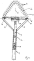
- FIGS. 1 to 5 Different views of a possible embodiment of a cleaning brush according to the invention for a toilet bowl, a urinal or the like are exemplified.
- the cleaning brush comprises a handle part 1 and a brush head 2, wherein the brush head 2 is movably mounted on the handle part 1.
- the brush head 2 has a frame element 3 which revolves or is closed in a plane or a frame structure revolving in a plane, from the surface of which a plurality of cleaning bristles 4 protrude.
- the frame element 3 is in the FIGS. 1 and 2 exemplified as a trapezoidal shape with four side areas, wherein the frame member 3 in cross-section in approximately a circular or depending on the application may have a polygonal shape. However, it is readily possible that the frame member 3 forms a triangular shape with only three side areas instead of a trapezoidal shape.
- an isosceles shape may be provided as a trapezoid or triangle. Regardless of the trapezoidal shape or triangular shape, the cleaning brush virtually achieves a flat, narrow cleaning area.
- the brush head 2 formed by the frame element 3 and the bristles 4 has a height H of about 6 to 10 cm and a thickness D of 2 to 3 cm, depending on the application.
- the mobility of the brush head 2 is realized by a lockable pivoting movement.
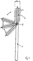
- FIG. 2 Various possible pivoting angle positions of the brush head 2 are indicated by way of example relative to the handle part 1, wherein the pivot angle direction is represented by double arrows.
- the locking element 9 is received in the interior of the handle part 1 in a recess and movable in the longitudinal direction against a spring force of a return spring 10 in the recess of the handle part 1, which in FIG. 1 indicated by corresponding arrows.
- the brush head 2 facing the end of the locking element 9 can be brought into operative connection with a latching of the brush head 2 for temporary locking.
- a toothed portion 11 is provided on the locking element 9 facing side of the brush head 2, in which a provided on the facing end of the locking element 9 pin portion 15 engages positively locking.
- the locking element 9 can be moved against the spring force to change the swing angle can. Once the predetermined pivot angle is reached, the locking element 9 is locked again in the toothed portion 11 of the brush head 2.
- the mutually facing ends 16, 17 of the support arms 6, 7 of the handle part 1 are designed approximately bolt-shaped and received in respectively corresponding sleeve-shaped sections 13, 14 of the brush head 2 for realizing the pivoting movement.
- the support arms 6, 7 are fixed or molded elastically to the handle part 1, so that the change of the brush head 2, the support arms 6, 7 can be bent according to apart to remove the old brush head 2 and to attach a new brush head 2.
- the proposed cleaning brush is a multi-part, preferably designed in three parts, consisting of the handle part 1, the locking element 9 and the brush head 2, wherein the handle part 1 and the locking element 9 can also be made in one piece.
Landscapes
- Health & Medical Sciences (AREA)
- Public Health (AREA)
- Non-Flushing Toilets (AREA)
- Brushes (AREA)
Abstract
Description
- Die vorliegende Erfindung betrifft eine Reinigungsbürste für ein Toilettenbecken, ein Urinal oder dergleichen, wobei die Reinigungsbürste zumindest ein Griffteil und einen Bürstenkopf aufweist und wobei der Bürstenkopf bewegbar an dem Griffteil gelagert ist.
- Beispielsweise aus der Druckschrift
EP 1 020 156 B1 ist eine Toilettenbürste mit einer lang gestreckten Handhabe mit einer ersten Achse und mit einem Bürstenkopf mit einer zweiten Achse bekannt, wobei die Handhabe über ein flexibles Gelenk mit dem Bürstenkopf verbunden ist. Der Bürstenkopf weist mit seinen daran befestigten Borsten eine Kugelkopfform auf. Durch die Bewegbarkeit zwischen Bürstenkopf und Handhabe ist es möglich, den Bürstenkopf in den gebogenen Ablaufbereich der Toilettenschüssel oder des Urinals einzuführen. Jedoch hat sich gezeigt, dass mit der bekannten Toilettenbürste aufgrund der Kugelkopfform des Bürstenkopfes beispielsweise schwer zugängliche Innenrandbereiche der Toilettenschüssel oder des Urinals nicht zu erreichen sind, sodass keine vollständige Reinigung der Toilettenanlage möglich ist. Demzufolge lagern sich in diesen Bereichen unerwünschte Verschmutzungen ab, die zu unerwünschten ästhetischen Belästigungen und auch zu Geruchsbelästigungen führen. - Der vorliegenden Erfindung liegt die Aufgabe zugrunde, eine Reinigungsbürste der eingangs beschriebenen Gattung derart auszuführen, dass die Reinigungsleistung erhöht wird und insbesondere die vorbeschriebenen Probleme vermieden werden.
- Diese Aufgabe wird erfindungsgemäß durch die Merkmale des Patentanspruchs 1 gelöst, wobei sich vorteilhafte und beanspruchte Weiterbildungen aus den Unteransprüchen und der Beschreibung sowie den Zeichnungen ergeben.
- Demzufolge wird eine Reinigungsbürste für ein Toilettenbecken, ein Urinal oder dergleichen mit zumindest einem Griffteil und einem Bürstenkopf vorgeschlagen, wobei der Bürstenkopf bewegbar an dem Griffteil gelagert ist. Um die Reinigungsleistung zu erhöhen, ist vorgesehen, dass der Bürstenkopf zumindest ein in einer Ebene umlaufendes bzw. geschlossenes Rahmenelement bzw. -teil oder dergleichen aufweist, von dessen Oberfläche eine Vielzahl von Reinigungsborsten abstehen.
- Auf diese Weise wird ein flächiger und bezogen auf die flächige Ausdehnung dünner Bürstenkopf realisiert, mit dem auch besonders schmale Bereiche, wie zum Beispiel der innere Beckenrand des Toilettenbeckens, des Urinals oder auch bei anderen Sanitäranlagen oder -becken ohne weiteres gereinigt werden können, sodass insgesamt die Reinigungsleistung mit der erfindungsgemäßen Reinigungsbürste deutlich erhöht wird. Mit der vorgeschlagenen Reinigungsbürste kann somit das gesamte Sanitärbecken gereinigt werden, sodass mit der Reinigungsbürste Kalk, Urinstein, Bakterien oder dergleichen vollständig entfernt werden können.
- Um eine optimale Reinigungsleistung mit der vorgeschlagenen Reinigungsbürste zu realisieren, hat sich eine Trapezform oder eine Dreiecksform des Rahmenelements als besonders vorteilhaft herauskristallisiert. Aufgrund der vorgenannten Formen des Rahmenelements wird quasi ein flächiger Reinigungsbereich gebildet, mit dem eine besonders gute Reinigung der schwer zugänglichen, schmalen Bereiche ermöglicht wird.
- Die bewegliche Anbindung des Bürstenkopfes an dem Griffteil ist vorteilhaft, um auch hinterschnittene oder gekrümmte Bereiche reinigen zu können. Besonders vorteilhaft hierbei ist es, wenn die Bewegbarkeit des Bürstenkopfes durch eine arretierbare Schwenkbewegung realisiert wird. Hierzu ist es zunächst möglich, den erforderlichen Schwenkwinkel einzustellen und anschließend zu arretieren. Beim nachfolgenden Reinigen kann ein ausreichender Druck auf den Bürstenkopf ohne die Gefahr der Schwenkwinkelverstellung aufgebracht werden, wodurch die Reinigungsleistung weiter erhöht wird.
- Beispielsweise kann der Bürstenkopf als quasi eine schmale bzw. eine mit geringer Dicke bezogen auf die Seitenfläche bildende Rahmenstruktur eine Höhe von etwa 6 bis 10 cm, vorzugsweise 8 cm und eine Dicke von 2 cm bis 3 cm vorzugsweise 2,5 cm aufweisen. Die bevorzugten Abmessungen haben sich als besonders vorteilhaft ergeben. Es sind jedoch auch andere Abmessungen verwendbar, um die erfindungsgemäße Reinigungsbürste auf abweichende Abmessungen der zu reinigenden Objekte anzupassen.
- Nachfolgend wird die folgende Erfindung anhand der Zeichnungen weiter erläutert. Es zeigen:
-
Figur 1 eine schematische Ansicht einer möglichen Ausführungsvariante einer erfindungsgemäßen Reinigungsbürste; -
Figur 2 eine Seitenansicht der Reinigungsbürste gemäßFigur 1 in verschiedenen Schwenkwinkeldarstellungen; -
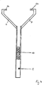
Figur 3 eine Einzelteilansicht eines Bürstenkopfes der Reinigungsbürste; -
Figur 4 eine Einzelteilansicht eines Griffteiles der Reinigungsbürste; und -
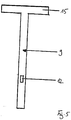
Figur 5 eine Einzelteilansicht eines Feststellelementes der Reinigungsbürste. - In den
Figuren 1 bis 5 sind verschiedene Ansichten einer möglichen Ausführungsvariante einer erfindungsgemäßen Reinigungsbürste für ein Toilettenbecken, ein Urinal oder dergleichen beispielhaft dargestellt. - Die Reinigungsbürste umfasst ein Griffteil 1 und einen Bürstenkopf 2, wobei der Bürstenkopf 2 bewegbar an dem Griffteil 1 gelagert ist. Um die Reinigungsleistung der Reinigungsbürste zu erhöhen, ist vorgesehen, dass der Bürstenkopf 2 ein in einer Ebene umlaufendes bzw. geschlossenes Rahmenelement 3 bzw. eine in einer Ebene umlaufende Rahmenstruktur aufweist, von dessen bzw. deren Oberfläche eine Vielzahl von Reinigungsborsten 4 abstehen.
- Das Rahmenelement 3 ist in den
Figuren 1 und2 beispielhaft als eine Trapezform mit vier Seitenbereichen ausgeführt, wobei das Rahmenelement 3 im Querschnitt in etwa eine kreisförmig oder auch je nach Anwendung eine mehreckige Gestalt aufweisen kann. Jedoch ist es ohne weiteres möglich, dass das Rahmenelement 3 anstelle einer Trapezform auch eine Dreiecksform mit nur drei Seitenbereichen bildet. - Vorzugsweise kann eine gleichschenklige Form als Trapez oder Dreieck vorgesehen sein. Unabhängig von der Trapezform oder Dreiecksform wird bei der Reinigungsbürste quasi ein flächiger, schmaler Reinigungsbereich realisiert. Der durch das Rahmenelement 3 und die Borsten 4 gebildete Bürstenkopf 2 weist eine Höhe H von etwa 6 bis 10 cm und eine Dicke D von 2 bis 3 cm je nach Anwendungsbereich auf.
- Wie insbesondere aus den
Figuren 1 und2 ersichtlich ist, wird die Bewegbarkeit des Bürstenkopfes 2 durch eine arretierbare Schwenkbewegung realisiert. InFigur 2 sind verschiedene mögliche Schwenkwinkelstellungen des Bürstenkopfes 2 relativ zum Griffteil 1 beispielhaft angedeutet, wobei die Schwenkwinkelrichtung durch Doppelpfeile dargestellt ist. - Um die Schwenkbarkeit zu realisieren, ist vorgesehen, dass an dem länglichen Griffteil 1 bezogen auf eine Längsachse 5 des Griffteiles 1 zwei symmetrisch ausgerichtete, gegenüberliegende Haltearme 6, 7 vorgesehen sind, an deren einander zugewandten Enden 16, 17 der Bürstenkopf 2 um eine quer zur Längsachse 5 des Griffteiles 1 ausgerichtete Schwenkachse 8 schwenkbar aufgenommen ist. Die Schwenkbewegung ist durch ein Feststellelement 9 in vorbestimmten Schwenkwinkeln arretierbar. Die Arretierung des Bürstenkopfes 2 wird durch ein Feststellelement 9 realisiert.
- Das Feststellelement 9 ist im Inneren des Griffteiles 1 in einer Ausnehmung aufgenommen und in Längsrichtung gegen eine Federkraft einer Rückstellfeder 10 in der Ausnehmung des Griffteiles 1 bewegbar, welches in
Figur 1 durch entsprechende Pfeile angedeutet ist. Das dem Bürstenkopf 2 zugewandte Ende des Feststellelementes 9 ist mit einer Verrastung des Bürstenkopfes 2 zur zeitweisen Arretierung in Wirkverbindung bringbar. Als Verrastung ist ein Verzahnungsabschnitt 11 an der dem Feststellelement 9 zugewandten Seite des Bürstenkopfes 2 vorgesehen, in den ein an dem zugewandten Ende des Feststellelementes 9 vorgesehener Zapfenabschnitt 15 zum Arretieren formschlüssig eingreift. Durch das Betätigen eines Betätigungsknopfes 12 an dem Feststellelement 9 kann das Feststellelement 9 gegen die Federkraft bewegt werden, um den Schwenkwinkel ändern zu können. Sobald der vorbestimmte Schwenkwinkel erreicht ist, wird das Feststellelement 9 wieder in dem Verzahnungsabschnitt 11 des Bürstenkopfes 2 arretiert. - Die einander zugewandten Enden 16, 17 der Haltearme 6, 7 des Griffteiles 1 sind etwa bolzenförmig ausgeführt und in jeweils korrespondierenden hülsenförmigen Abschnitten 13, 14 des Bürstenkopfes 2 zum Realisieren der Schwenkbewegung aufgenommen.
- Um beispielsweise den Bürstenkopf 2 wechseln zu können, sind die Haltearme 6, 7 elastisch an den Griffteil 1 befestigt bzw. angeformt, sodass zum Wechsel des Bürstenkopfes 2 die Haltearme 6, 7 entsprechend auseinander gebogen werden können, um den alten Bürstenkopf 2 zu entnehmen und einen neuen Bürstenkopf 2 zu befestigen. Demzufolge ist die vorgeschlagene Reinigungsbürste mehrteilig, vorzugsweise dreiteilig ausgeführt, bestehend aus dem Griffteil 1, dem Feststellelement 9 und dem Bürstenkopf 2, wobei das Griffteil 1 und das Feststellelement 9 auch einteilig ausgeführt werden können.
-
- 1
- Griffteil
- 2
- Bürstenkopf
- 3
- Rahmenelement
- 4
- Reinigungsborsten
- 5
- Längsachse
- 6
- Haltearm
- 7
- Haltearm
- 8
- Schwenkachse
- 9
- Feststellelement
- 10
- Rückstellfeder
- 11
- Verzahnungsabschnitt
- 12
- Betätigungsknopf
- 13
- hülsenförmiger Abschnitt
- 14
- hülsenförmiger Abschnitt
- 15
- Zapfenabschnitt
- 16
- Ende des Haltearms
- 17
- Ende des Haltearms
- H
- Höhe des Bürstenkopfes
- D
- Dicke des Bürstenkopfes
Claims (9)
- Reinigungsbürste für ein Toilettenbecken oder ein Urinal, mit zumindest einem Griffteil (1) und einem Bürstenkopf (2), wobei der Bürstenkopf (2) bewegbar an dem Griffteil (1) gelagert ist, dadurch gekennzeichnet, dass der Bürstenkopf (2) zumindest ein in einer Ebene umlaufendes Rahmenelement (3) aufweist, von dessen Oberfläche eine Vielzahl von Reinigungsborsten (4) abstehen.
- Reinigungsbürste nach Anspruch 1, dadurch gekennzeichnet, dass das Rahmenelement (3) eine Trapez- oder Dreiecksform bildet.
- Reinigungsbürste nach Anspruch 1 oder 2, dadurch gekennzeichnet, dass der durch das Rahmenelement (3) und die Reinigungsborsten (4) gebildete Bürstenkopf (2) eine Höhe (H) von etwa 6 cm bis 10 cm, vorzugsweis 8 cm und eine Dicke (D) von 2 cm bis 3cm, vorzugsweise 2,5 cm aufweist.
- Reinigungsbürste nach einem der vorangehenden Ansprüche, dadurch gekennzeichnet, dass die Bewegbarkeit des Bürstenkopfes (2) an dem Griffteil (1) durch eine in vorbestimmten Schwenkwinkeln arretierbare Schwenkbewegung realisiert ist.
- Reinigungsbürste nach einem der vorangehenden Ansprüche, dadurch gekennzeichnet, dass an dem länglichen Griffteil (1) zwei bezogen auf eine Längsachse (5) des Griffteiles (1) symmetrisch ausgerichtete Haltearme (6, 7) vorgesehen sind, an deren einander zugewandten Enden der Bürsten kopf (2) um eine quer zur Längsachse (5) des Griffteiles (1) ausgerichtete Schwenkachse (8) schwenkbar aufgenommen ist, wobei die Schwenkbewegung durch ein Feststellelement (9) in vorbestimmten Schwenkwinkeln arretierbar ist.
- Reinigungsanordnung nach Anspruch 5, dadurch gekennzeichnet, dass das Feststellelement (9) in einer Ausnehmung des Griffteiles (1) aufgenommen ist und in Längsrichtung gegen eine Federkraft einer Rückstellfeder (10) relativ zum Griffteil (1) bewegbar ist, wobei das dem Bürstenkopf (2) zugewandte Ende des Feststellelementes (9) mit einer Verrastung des Bürstenkopfes (2) zur zeitweisen Arretierung in Wirkverbindung bringbar ist.
- Reinigungsbürste nach Anspruch 6, dadurch gekennzeichnet, dass als Verrastung ein Verzahnungsabschnitt (11) an der dem Feststellelement (9) zugewandten Seite des Bürstenkopfes (2) vorgesehen ist, in den ein an dem zugewandten Ende des Feststellelementes (9) vorgesehener Zapfenabschnitt (15) zum Arretieren formschlüssig eingreift.
- Reinigungsanordnung nach einem der Ansprüche 5 bis 7, dadurch gekennzeichnet, dass die einander zugewandten Enden (16, 17) der Haltearme (6, 7) des Griffteiles (1) etwa bolzenförmig ausgeführt sind, und jeweils in korrespondierenden hülsenförmigen Abschnitten (13, 14) des Bürstenkopfes (2) zum Realisieren der Schwenkbewegung aufgenommen sind.
- Reinigungsanordnung nach einem der Ansprüche 5 bis 8, dadurch gekennzeichnet, dass die Haltearme (6, 7) elastisch an dem Griffteil (1) befestigt sind.
Applications Claiming Priority (1)
| Application Number | Priority Date | Filing Date | Title |
|---|---|---|---|
| DE102018100914.3A DE102018100914B3 (de) | 2018-01-17 | 2018-01-17 | Reinigungsbürste für ein Toilettenbecken oder ein Urinal |
Publications (2)
| Publication Number | Publication Date |
|---|---|
| EP3513700A1 true EP3513700A1 (de) | 2019-07-24 |
| EP3513700B1 EP3513700B1 (de) | 2021-03-10 |
Family
ID=64568137
Family Applications (1)
| Application Number | Title | Priority Date | Filing Date |
|---|---|---|---|
| EP19151186.4A Active EP3513700B1 (de) | 2018-01-17 | 2019-01-10 | Reinigungsbürste für ein toilettenbecken |
Country Status (2)
| Country | Link |
|---|---|
| EP (1) | EP3513700B1 (de) |
| DE (1) | DE102018100914B3 (de) |
Citations (3)
| Publication number | Priority date | Publication date | Assignee | Title |
|---|---|---|---|---|
| US3000029A (en) * | 1960-01-08 | 1961-09-19 | Stuart G Wood | Bath tub cleaning brush |
| DE202010003226U1 (de) * | 2010-03-02 | 2010-06-10 | Hanses, Klemens | Toilettenbürste |
| DE202010010671U1 (de) * | 2010-07-22 | 2010-12-02 | Steffen, Wolfgang | Toilettenbürste mit auswechselbarem Bürstenkopf |
Family Cites Families (5)
| Publication number | Priority date | Publication date | Assignee | Title |
|---|---|---|---|---|
| US2464085A (en) * | 1946-04-27 | 1949-03-08 | Ethel M Hess | Toilet brush container |
| US2878501A (en) * | 1957-09-20 | 1959-03-24 | J S Costello & Son Brush Compa | Brush |
| US6154913A (en) | 1999-01-06 | 2000-12-05 | General Housewares Corp. | Flexibly jointed toilet brush |
| CZ14345U1 (cs) | 2004-03-29 | 2004-05-17 | Eta A. S. | Hubice s kartáčovou úpravou, především pro péči o zvířecí srst |
| JP2008508908A (ja) * | 2004-07-10 | 2008-03-27 | ユニリーバー・ナームローゼ・ベンノートシヤープ | 清掃パッド用の把持手段を備える清掃装置 |
-
2018
- 2018-01-17 DE DE102018100914.3A patent/DE102018100914B3/de active Active
-
2019
- 2019-01-10 EP EP19151186.4A patent/EP3513700B1/de active Active
Patent Citations (3)
| Publication number | Priority date | Publication date | Assignee | Title |
|---|---|---|---|---|
| US3000029A (en) * | 1960-01-08 | 1961-09-19 | Stuart G Wood | Bath tub cleaning brush |
| DE202010003226U1 (de) * | 2010-03-02 | 2010-06-10 | Hanses, Klemens | Toilettenbürste |
| DE202010010671U1 (de) * | 2010-07-22 | 2010-12-02 | Steffen, Wolfgang | Toilettenbürste mit auswechselbarem Bürstenkopf |
Also Published As
| Publication number | Publication date |
|---|---|
| EP3513700B1 (de) | 2021-03-10 |
| DE102018100914B3 (de) | 2018-12-27 |
Similar Documents
| Publication | Publication Date | Title |
|---|---|---|
| EP2851497B1 (de) | Justierbare Montagevorrichtung für ein Schiebeelement sowie Schiebevorrichtung | |
| EP1189764A1 (de) | Ringordnermechanik | |
| DE112016005075T5 (de) | Scharnier für ein Dachfenster und ein Dachfenster umfassend einen Satz von Scharnieren | |
| WO2004065136A2 (de) | Mehrzahl von riegelelementen in einer ringordnermechanik | |
| WO1990005827A1 (de) | In türen und wände einsetzbare durchreichevorrichtung | |
| DE60306221T2 (de) | Vorrichtung zum Öffnen und Schliessen eines Stöpsels einer Ablaufgarnitur | |
| DE2517641A1 (de) | Klinkeneinheit | |
| WO2004095997A1 (de) | Raumteiler | |
| DE102020108936A1 (de) | Abwassertankanordnung für ein Flugzeug | |
| EP3985216B1 (de) | Flügelanordnung | |
| DE2839587A1 (de) | Wischblatt, insbesondere fue scheibenreinigungsanlagen in kraftfahrzeugen | |
| EP2792830B1 (de) | Beschlagteil mit halteelement zur halterung des beschlagteils | |
| EP1613828B1 (de) | Vorrichtung zum schliessen einer t re | |
| EP4438836A1 (de) | Schliesssystem und tür oder fenster mit derartigem schliesssystem | |
| DE202009016669U1 (de) | Möbel, Möbelteil und Vorrichtung zur Verbindung eines Frontbauteils eines Möbelteils | |
| DE102018100914B3 (de) | Reinigungsbürste für ein Toilettenbecken oder ein Urinal | |
| WO2003094756A1 (de) | Schere für medizinische zwecke | |
| EP4105416B1 (de) | Feststellvorrichtung für beidseitig angeschlagene tür | |
| DE102019133319A1 (de) | Unterflurinstallationsbauteil | |
| EP2578759A1 (de) | Verriegelungsmechanismus für Ablauf | |
| DE8535142U1 (de) | Ausziehtisch | |
| DE102004054863B4 (de) | Handwischer, insbesondere für Rundduschen | |
| DE102005003394B4 (de) | Führungssystem, insbesondere für Dusch- und Badewannenabtrennungen | |
| AT413574B (de) | Beschlag zur gegenseitigen schwenkverstellung zweier möbelteile | |
| EP1177073B1 (de) | Reinigungsgerät für kraftfahrzeuge |
Legal Events
| Date | Code | Title | Description |
|---|---|---|---|
| PUAI | Public reference made under article 153(3) epc to a published international application that has entered the european phase |
Free format text: ORIGINAL CODE: 0009012 |
|
| STAA | Information on the status of an ep patent application or granted ep patent |
Free format text: STATUS: THE APPLICATION HAS BEEN PUBLISHED |
|
| AK | Designated contracting states |
Kind code of ref document: A1 Designated state(s): AL AT BE BG CH CY CZ DE DK EE ES FI FR GB GR HR HU IE IS IT LI LT LU LV MC MK MT NL NO PL PT RO RS SE SI SK SM TR |
|
| AX | Request for extension of the european patent |
Extension state: BA ME |
|
| STAA | Information on the status of an ep patent application or granted ep patent |
Free format text: STATUS: REQUEST FOR EXAMINATION WAS MADE |
|
| 17P | Request for examination filed |
Effective date: 20200114 |
|
| RBV | Designated contracting states (corrected) |
Designated state(s): AL AT BE BG CH CY CZ DE DK EE ES FI FR GB GR HR HU IE IS IT LI LT LU LV MC MK MT NL NO PL PT RO RS SE SI SK SM TR |
|
| GRAP | Despatch of communication of intention to grant a patent |
Free format text: ORIGINAL CODE: EPIDOSNIGR1 |
|
| STAA | Information on the status of an ep patent application or granted ep patent |
Free format text: STATUS: GRANT OF PATENT IS INTENDED |
|
| INTG | Intention to grant announced |
Effective date: 20201113 |
|
| GRAS | Grant fee paid |
Free format text: ORIGINAL CODE: EPIDOSNIGR3 |
|
| GRAA | (expected) grant |
Free format text: ORIGINAL CODE: 0009210 |
|
| STAA | Information on the status of an ep patent application or granted ep patent |
Free format text: STATUS: THE PATENT HAS BEEN GRANTED |
|
| AK | Designated contracting states |
Kind code of ref document: B1 Designated state(s): AL AT BE BG CH CY CZ DE DK EE ES FI FR GB GR HR HU IE IS IT LI LT LU LV MC MK MT NL NO PL PT RO RS SE SI SK SM TR |
|
| REG | Reference to a national code |
Ref country code: GB Ref legal event code: FG4D Free format text: NOT ENGLISH |
|
| REG | Reference to a national code |
Ref country code: CH Ref legal event code: EP Ref country code: AT Ref legal event code: REF Ref document number: 1368836 Country of ref document: AT Kind code of ref document: T Effective date: 20210315 |
|
| REG | Reference to a national code |
Ref country code: IE Ref legal event code: FG4D Free format text: LANGUAGE OF EP DOCUMENT: GERMAN |
|
| REG | Reference to a national code |
Ref country code: DE Ref legal event code: R096 Ref document number: 502019000926 Country of ref document: DE |
|
| REG | Reference to a national code |
Ref country code: LT Ref legal event code: MG9D |
|
| PG25 | Lapsed in a contracting state [announced via postgrant information from national office to epo] |
Ref country code: NO Free format text: LAPSE BECAUSE OF FAILURE TO SUBMIT A TRANSLATION OF THE DESCRIPTION OR TO PAY THE FEE WITHIN THE PRESCRIBED TIME-LIMIT Effective date: 20210610 Ref country code: LT Free format text: LAPSE BECAUSE OF FAILURE TO SUBMIT A TRANSLATION OF THE DESCRIPTION OR TO PAY THE FEE WITHIN THE PRESCRIBED TIME-LIMIT Effective date: 20210310 Ref country code: BG Free format text: LAPSE BECAUSE OF FAILURE TO SUBMIT A TRANSLATION OF THE DESCRIPTION OR TO PAY THE FEE WITHIN THE PRESCRIBED TIME-LIMIT Effective date: 20210610 Ref country code: HR Free format text: LAPSE BECAUSE OF FAILURE TO SUBMIT A TRANSLATION OF THE DESCRIPTION OR TO PAY THE FEE WITHIN THE PRESCRIBED TIME-LIMIT Effective date: 20210310 Ref country code: FI Free format text: LAPSE BECAUSE OF FAILURE TO SUBMIT A TRANSLATION OF THE DESCRIPTION OR TO PAY THE FEE WITHIN THE PRESCRIBED TIME-LIMIT Effective date: 20210310 Ref country code: GR Free format text: LAPSE BECAUSE OF FAILURE TO SUBMIT A TRANSLATION OF THE DESCRIPTION OR TO PAY THE FEE WITHIN THE PRESCRIBED TIME-LIMIT Effective date: 20210611 |
|
| REG | Reference to a national code |
Ref country code: NL Ref legal event code: MP Effective date: 20210310 |
|
| PG25 | Lapsed in a contracting state [announced via postgrant information from national office to epo] |
Ref country code: SE Free format text: LAPSE BECAUSE OF FAILURE TO SUBMIT A TRANSLATION OF THE DESCRIPTION OR TO PAY THE FEE WITHIN THE PRESCRIBED TIME-LIMIT Effective date: 20210310 Ref country code: LV Free format text: LAPSE BECAUSE OF FAILURE TO SUBMIT A TRANSLATION OF THE DESCRIPTION OR TO PAY THE FEE WITHIN THE PRESCRIBED TIME-LIMIT Effective date: 20210310 Ref country code: RS Free format text: LAPSE BECAUSE OF FAILURE TO SUBMIT A TRANSLATION OF THE DESCRIPTION OR TO PAY THE FEE WITHIN THE PRESCRIBED TIME-LIMIT Effective date: 20210310 |
|
| PG25 | Lapsed in a contracting state [announced via postgrant information from national office to epo] |
Ref country code: NL Free format text: LAPSE BECAUSE OF FAILURE TO SUBMIT A TRANSLATION OF THE DESCRIPTION OR TO PAY THE FEE WITHIN THE PRESCRIBED TIME-LIMIT Effective date: 20210310 |
|
| PG25 | Lapsed in a contracting state [announced via postgrant information from national office to epo] |
Ref country code: EE Free format text: LAPSE BECAUSE OF FAILURE TO SUBMIT A TRANSLATION OF THE DESCRIPTION OR TO PAY THE FEE WITHIN THE PRESCRIBED TIME-LIMIT Effective date: 20210310 Ref country code: CZ Free format text: LAPSE BECAUSE OF FAILURE TO SUBMIT A TRANSLATION OF THE DESCRIPTION OR TO PAY THE FEE WITHIN THE PRESCRIBED TIME-LIMIT Effective date: 20210310 Ref country code: SM Free format text: LAPSE BECAUSE OF FAILURE TO SUBMIT A TRANSLATION OF THE DESCRIPTION OR TO PAY THE FEE WITHIN THE PRESCRIBED TIME-LIMIT Effective date: 20210310 |
|
| PG25 | Lapsed in a contracting state [announced via postgrant information from national office to epo] |
Ref country code: SK Free format text: LAPSE BECAUSE OF FAILURE TO SUBMIT A TRANSLATION OF THE DESCRIPTION OR TO PAY THE FEE WITHIN THE PRESCRIBED TIME-LIMIT Effective date: 20210310 Ref country code: PT Free format text: LAPSE BECAUSE OF FAILURE TO SUBMIT A TRANSLATION OF THE DESCRIPTION OR TO PAY THE FEE WITHIN THE PRESCRIBED TIME-LIMIT Effective date: 20210712 Ref country code: RO Free format text: LAPSE BECAUSE OF FAILURE TO SUBMIT A TRANSLATION OF THE DESCRIPTION OR TO PAY THE FEE WITHIN THE PRESCRIBED TIME-LIMIT Effective date: 20210310 Ref country code: PL Free format text: LAPSE BECAUSE OF FAILURE TO SUBMIT A TRANSLATION OF THE DESCRIPTION OR TO PAY THE FEE WITHIN THE PRESCRIBED TIME-LIMIT Effective date: 20210310 Ref country code: IS Free format text: LAPSE BECAUSE OF FAILURE TO SUBMIT A TRANSLATION OF THE DESCRIPTION OR TO PAY THE FEE WITHIN THE PRESCRIBED TIME-LIMIT Effective date: 20210710 |
|
| REG | Reference to a national code |
Ref country code: DE Ref legal event code: R097 Ref document number: 502019000926 Country of ref document: DE |
|
| PLBE | No opposition filed within time limit |
Free format text: ORIGINAL CODE: 0009261 |
|
| STAA | Information on the status of an ep patent application or granted ep patent |
Free format text: STATUS: NO OPPOSITION FILED WITHIN TIME LIMIT |
|
| PG25 | Lapsed in a contracting state [announced via postgrant information from national office to epo] |
Ref country code: ES Free format text: LAPSE BECAUSE OF FAILURE TO SUBMIT A TRANSLATION OF THE DESCRIPTION OR TO PAY THE FEE WITHIN THE PRESCRIBED TIME-LIMIT Effective date: 20210310 Ref country code: AL Free format text: LAPSE BECAUSE OF FAILURE TO SUBMIT A TRANSLATION OF THE DESCRIPTION OR TO PAY THE FEE WITHIN THE PRESCRIBED TIME-LIMIT Effective date: 20210310 Ref country code: DK Free format text: LAPSE BECAUSE OF FAILURE TO SUBMIT A TRANSLATION OF THE DESCRIPTION OR TO PAY THE FEE WITHIN THE PRESCRIBED TIME-LIMIT Effective date: 20210310 |
|
| 26N | No opposition filed |
Effective date: 20211213 |
|
| PG25 | Lapsed in a contracting state [announced via postgrant information from national office to epo] |
Ref country code: SI Free format text: LAPSE BECAUSE OF FAILURE TO SUBMIT A TRANSLATION OF THE DESCRIPTION OR TO PAY THE FEE WITHIN THE PRESCRIBED TIME-LIMIT Effective date: 20210310 |
|
| PG25 | Lapsed in a contracting state [announced via postgrant information from national office to epo] |
Ref country code: IT Free format text: LAPSE BECAUSE OF FAILURE TO SUBMIT A TRANSLATION OF THE DESCRIPTION OR TO PAY THE FEE WITHIN THE PRESCRIBED TIME-LIMIT Effective date: 20210310 |
|
| PG25 | Lapsed in a contracting state [announced via postgrant information from national office to epo] |
Ref country code: IS Free format text: LAPSE BECAUSE OF FAILURE TO SUBMIT A TRANSLATION OF THE DESCRIPTION OR TO PAY THE FEE WITHIN THE PRESCRIBED TIME-LIMIT Effective date: 20210710 |
|
| PG25 | Lapsed in a contracting state [announced via postgrant information from national office to epo] |
Ref country code: MC Free format text: LAPSE BECAUSE OF FAILURE TO SUBMIT A TRANSLATION OF THE DESCRIPTION OR TO PAY THE FEE WITHIN THE PRESCRIBED TIME-LIMIT Effective date: 20210310 |
|
| REG | Reference to a national code |
Ref country code: BE Ref legal event code: MM Effective date: 20220131 |
|
| PG25 | Lapsed in a contracting state [announced via postgrant information from national office to epo] |
Ref country code: LU Free format text: LAPSE BECAUSE OF NON-PAYMENT OF DUE FEES Effective date: 20220110 |
|
| PG25 | Lapsed in a contracting state [announced via postgrant information from national office to epo] |
Ref country code: FR Free format text: LAPSE BECAUSE OF NON-PAYMENT OF DUE FEES Effective date: 20220131 Ref country code: BE Free format text: LAPSE BECAUSE OF NON-PAYMENT OF DUE FEES Effective date: 20220131 |
|
| PG25 | Lapsed in a contracting state [announced via postgrant information from national office to epo] |
Ref country code: IE Free format text: LAPSE BECAUSE OF NON-PAYMENT OF DUE FEES Effective date: 20220110 |
|
| GBPC | Gb: european patent ceased through non-payment of renewal fee |
Effective date: 20230110 |
|
| PG25 | Lapsed in a contracting state [announced via postgrant information from national office to epo] |
Ref country code: GB Free format text: LAPSE BECAUSE OF NON-PAYMENT OF DUE FEES Effective date: 20230110 |
|
| PG25 | Lapsed in a contracting state [announced via postgrant information from national office to epo] |
Ref country code: MK Free format text: LAPSE BECAUSE OF FAILURE TO SUBMIT A TRANSLATION OF THE DESCRIPTION OR TO PAY THE FEE WITHIN THE PRESCRIBED TIME-LIMIT Effective date: 20210310 Ref country code: CY Free format text: LAPSE BECAUSE OF FAILURE TO SUBMIT A TRANSLATION OF THE DESCRIPTION OR TO PAY THE FEE WITHIN THE PRESCRIBED TIME-LIMIT Effective date: 20210310 |
|
| PG25 | Lapsed in a contracting state [announced via postgrant information from national office to epo] |
Ref country code: HU Free format text: LAPSE BECAUSE OF FAILURE TO SUBMIT A TRANSLATION OF THE DESCRIPTION OR TO PAY THE FEE WITHIN THE PRESCRIBED TIME-LIMIT; INVALID AB INITIO Effective date: 20190110 |
|
| PG25 | Lapsed in a contracting state [announced via postgrant information from national office to epo] |
Ref country code: MT Free format text: LAPSE BECAUSE OF FAILURE TO SUBMIT A TRANSLATION OF THE DESCRIPTION OR TO PAY THE FEE WITHIN THE PRESCRIBED TIME-LIMIT Effective date: 20210310 |
|
| PGFP | Annual fee paid to national office [announced via postgrant information from national office to epo] |
Ref country code: DE Payment date: 20250113 Year of fee payment: 7 |
|
| PG25 | Lapsed in a contracting state [announced via postgrant information from national office to epo] |
Ref country code: TR Free format text: LAPSE BECAUSE OF FAILURE TO SUBMIT A TRANSLATION OF THE DESCRIPTION OR TO PAY THE FEE WITHIN THE PRESCRIBED TIME-LIMIT Effective date: 20210310 |
|
| REG | Reference to a national code |
Ref country code: CH Ref legal event code: U11 Free format text: ST27 STATUS EVENT CODE: U-0-0-U10-U11 (AS PROVIDED BY THE NATIONAL OFFICE) Effective date: 20260201 |
|
| PGFP | Annual fee paid to national office [announced via postgrant information from national office to epo] |
Ref country code: AT Payment date: 20260120 Year of fee payment: 8 |
|
| PGFP | Annual fee paid to national office [announced via postgrant information from national office to epo] |
Ref country code: CH Payment date: 20260201 Year of fee payment: 8 |