EP3512706B1 - Tröpfchenabscheidungskopf und aktuatorkomponente dafür - Google Patents
Tröpfchenabscheidungskopf und aktuatorkomponente dafür Download PDFInfo
- Publication number
- EP3512706B1 EP3512706B1 EP16781527.3A EP16781527A EP3512706B1 EP 3512706 B1 EP3512706 B1 EP 3512706B1 EP 16781527 A EP16781527 A EP 16781527A EP 3512706 B1 EP3512706 B1 EP 3512706B1
- Authority
- EP
- European Patent Office
- Prior art keywords
- row
- inlet
- passageways
- outlet
- actuator component
- Prior art date
- Legal status (The legal status is an assumption and is not a legal conclusion. Google has not performed a legal analysis and makes no representation as to the accuracy of the status listed.)
- Active
Links
Images





Classifications
-
- B—PERFORMING OPERATIONS; TRANSPORTING
- B41—PRINTING; LINING MACHINES; TYPEWRITERS; STAMPS
- B41J—TYPEWRITERS; SELECTIVE PRINTING MECHANISMS, i.e. MECHANISMS PRINTING OTHERWISE THAN FROM A FORME; CORRECTION OF TYPOGRAPHICAL ERRORS
- B41J2/00—Typewriters or selective printing mechanisms characterised by the printing or marking process for which they are designed
- B41J2/005—Typewriters or selective printing mechanisms characterised by the printing or marking process for which they are designed characterised by bringing liquid or particles selectively into contact with a printing material
- B41J2/01—Ink jet
- B41J2/135—Nozzles
- B41J2/14—Structure thereof only for on-demand ink jet heads
- B41J2/14201—Structure of print heads with piezoelectric elements
- B41J2/14233—Structure of print heads with piezoelectric elements of film type, deformed by bending and disposed on a diaphragm
-
- B—PERFORMING OPERATIONS; TRANSPORTING
- B41—PRINTING; LINING MACHINES; TYPEWRITERS; STAMPS
- B41J—TYPEWRITERS; SELECTIVE PRINTING MECHANISMS, i.e. MECHANISMS PRINTING OTHERWISE THAN FROM A FORME; CORRECTION OF TYPOGRAPHICAL ERRORS
- B41J2/00—Typewriters or selective printing mechanisms characterised by the printing or marking process for which they are designed
- B41J2/005—Typewriters or selective printing mechanisms characterised by the printing or marking process for which they are designed characterised by bringing liquid or particles selectively into contact with a printing material
- B41J2/01—Ink jet
- B41J2/135—Nozzles
- B41J2/14—Structure thereof only for on-demand ink jet heads
- B41J2/14201—Structure of print heads with piezoelectric elements
- B41J2/14274—Structure of print heads with piezoelectric elements of stacked structure type, deformed by compression/extension and disposed on a diaphragm
-
- B—PERFORMING OPERATIONS; TRANSPORTING
- B41—PRINTING; LINING MACHINES; TYPEWRITERS; STAMPS
- B41J—TYPEWRITERS; SELECTIVE PRINTING MECHANISMS, i.e. MECHANISMS PRINTING OTHERWISE THAN FROM A FORME; CORRECTION OF TYPOGRAPHICAL ERRORS
- B41J2/00—Typewriters or selective printing mechanisms characterised by the printing or marking process for which they are designed
- B41J2/005—Typewriters or selective printing mechanisms characterised by the printing or marking process for which they are designed characterised by bringing liquid or particles selectively into contact with a printing material
- B41J2/01—Ink jet
- B41J2/135—Nozzles
- B41J2/14—Structure thereof only for on-demand ink jet heads
- B41J2/14201—Structure of print heads with piezoelectric elements
- B41J2/14233—Structure of print heads with piezoelectric elements of film type, deformed by bending and disposed on a diaphragm
- B41J2002/14241—Structure of print heads with piezoelectric elements of film type, deformed by bending and disposed on a diaphragm having a cover around the piezoelectric thin film element
-
- B—PERFORMING OPERATIONS; TRANSPORTING
- B41—PRINTING; LINING MACHINES; TYPEWRITERS; STAMPS
- B41J—TYPEWRITERS; SELECTIVE PRINTING MECHANISMS, i.e. MECHANISMS PRINTING OTHERWISE THAN FROM A FORME; CORRECTION OF TYPOGRAPHICAL ERRORS
- B41J2/00—Typewriters or selective printing mechanisms characterised by the printing or marking process for which they are designed
- B41J2/005—Typewriters or selective printing mechanisms characterised by the printing or marking process for which they are designed characterised by bringing liquid or particles selectively into contact with a printing material
- B41J2/01—Ink jet
- B41J2/135—Nozzles
- B41J2/14—Structure thereof only for on-demand ink jet heads
- B41J2002/14419—Manifold
-
- B—PERFORMING OPERATIONS; TRANSPORTING
- B41—PRINTING; LINING MACHINES; TYPEWRITERS; STAMPS
- B41J—TYPEWRITERS; SELECTIVE PRINTING MECHANISMS, i.e. MECHANISMS PRINTING OTHERWISE THAN FROM A FORME; CORRECTION OF TYPOGRAPHICAL ERRORS
- B41J2/00—Typewriters or selective printing mechanisms characterised by the printing or marking process for which they are designed
- B41J2/005—Typewriters or selective printing mechanisms characterised by the printing or marking process for which they are designed characterised by bringing liquid or particles selectively into contact with a printing material
- B41J2/01—Ink jet
- B41J2/135—Nozzles
- B41J2/14—Structure thereof only for on-demand ink jet heads
- B41J2002/14459—Matrix arrangement of the pressure chambers
-
- B—PERFORMING OPERATIONS; TRANSPORTING
- B41—PRINTING; LINING MACHINES; TYPEWRITERS; STAMPS
- B41J—TYPEWRITERS; SELECTIVE PRINTING MECHANISMS, i.e. MECHANISMS PRINTING OTHERWISE THAN FROM A FORME; CORRECTION OF TYPOGRAPHICAL ERRORS
- B41J2202/00—Embodiments of or processes related to ink-jet or thermal heads
- B41J2202/01—Embodiments of or processes related to ink-jet heads
- B41J2202/12—Embodiments of or processes related to ink-jet heads with ink circulating through the whole print head
Definitions
- the present invention relates to droplet deposition heads and actuator components therefor. It may find particularly beneficial application in a printhead, such as an inkjet printhead, and actuator components therefor.
- Droplet deposition heads are now in widespread usage, whether in more traditional applications, such as inkjet printing, or in 3D printing, or other materials deposition or rapid prototyping techniques. Accordingly, the fluids may have novel chemical properties to adhere to new substrates and increase the functionality of the deposited material.
- inkjet printheads have been developed that are capable of depositing ink directly onto ceramic tiles, with high reliability and throughput. This allows the patterns on the tiles to be customized to a customer's exact specifications, as well as reducing the need for a full range of tiles to be kept in stock.
- inkjet printheads have been developed that are capable of depositing ink directly on to textiles. As with ceramics applications, this may allow the patterns on the textiles to be customized to a customer's exact specifications, as well as reducing the need for a full range of printed textiles to be kept in stock.
- droplet deposition heads may be used to form elements such as colour filters in LCD or OLED elements displays used in flat-screen television manufacturing.
- droplet deposition heads continue to evolve and pursue. However, while a great many developments have been made, there remains room for improvements in the field of droplet deposition heads.
- EP 2 990 205 A2 discloses a liquid discharge head including plural liquid discharge portions each including a discharge port for discharging liquid, plural discharge ports forming a discharge port array; a common liquid supply flow path extending adjacent to the discharge port array on one side of the discharge port array; and a common liquid collection flow path extending adjacent to the discharge port array on the other side of the discharge port array.
- Each liquid discharge portion includes a pressure chamber having the discharge port, and a piezoelectric element facing the discharge port.
- the pressure chamber includes an inlet and an outlet end portion respectively connected to the common liquid supply and collection flow paths, and has an elongated shape connecting the inlet and outlet end portions.
- a plurality of inlet and outlet end portions are respectively arranged along the common liquid supply flow path and the common liquid collection flow path.
- US 2005/0179732 A1 discloses a small droplet discharging device capable of producing high-density arrays.
- the droplet discharging device comprises a first substrate comprising a plurality of reservoir chambers for holding a liquid, a second substrate comprising a plurality of discharge units comprising supply openings for receiving a supply of a liquid stored in the reservoir chambers, pressurizing chambers for applying a pressure to the liquid supplied from the supply openings, and discharge openings for discharging the liquid pressurized in the pressurizing chambers to the outside, and a third substrate sandwiched between the first substrate and the second substrate and comprising channels for connecting the plurality of reservoir chambers with the plurality of supply openings corresponding thereto, wherein the plurality of supply openings provided in the second substrate are arranged such that relative positions thereof have a zigzag disposition.
- the present invention is an actuator component as defined in Claim 1 of the appended claims. Also provided is a droplet deposition head as defined in Claim 15. Details of certain embodiments are set out in the dependent claims.
- an actuator component for a droplet deposition head comprising: an actuator component comprising a plurality of patterned layers, each layer extending in a plane having a normal in a layering direction, the layers being stacked one upon another in said layering direction ; a row of fluid chambers formed within said plurality of layers, the row extending in an row direction, which is substantially perpendicular to said layering direction, each fluid chamber being provided with a respective nozzle and a respective actuating element, which is actuable to cause the ejection of fluid from the chamber in question through the corresponding one of the nozzles; a row of inlet passageways formed within said plurality of layers, the row extending in said row direction, each inlet passageway being fluidically connected so as to supply fluid to a respective one of said fluid chambers; a row of outlet passageways formed within said plurality of layers, the row extending in said row direction, each outlet passageway being fluidically connected so as to receive fluid from a respective one of said fluid chambers.
- At least one of said row of inlet passageways and said row of outlet passageways is staggered, whereby at least some of the members of the staggered row in question are offset from their neighbours in an offset direction for the staggered row in question which that is perpendicular to said row direction.
- substantially all of the inlet passageways may have the same orientation.
- substantially all of the outlet passageways may have the same orientation.
- substantially all of the fluid chambers may have the same orientation.
- droplet deposition heads comprising such actuator components.
- Such droplet deposition heads may further comprise one or more manifold components that are attached to the actuator component.
- the manifold component(s) may convey fluid to the row of inlet passageways and may receive fluid from the row of outlet passageways.
- Such droplet deposition heads may, in addition, or instead, include drive circuitry that is electrically connected to the actuating elements, for example by means of electrical traces provided by the actuator component.
- Such drive circuitry may supply drive voltage signals to the actuating elements that cause the ejection of droplets from a selected group of chambers, with the selected group changing with changes in input data received by the head.
- an actuator component for a droplet deposition head comprising: an actuator component comprising a plurality of patterned layers, each layer extending in a plane having a normal in a layering direction, the layers being stacked one upon another in said layering direction; a row of fluid chambers formed within said plurality of layers, the row extending in an row direction, which is substantially perpendicular to said layering direction, each fluid chamber being provided with a respective nozzle and a respective actuating element, which is actuable to cause the ejection of fluid from the chamber in question through the corresponding one of the nozzles; at least a first row of inlet passageways formed within said plurality of layers, said first row extending in said row direction, each inlet passageway being fluidically connected so as to supply fluid to a respective one of said fluid chambers.
- the aforementioned first row of inlet passageways is staggered, whereby at least some of the members of the first row of inlet passageways are offset from their neighbours in an offset direction for the first row of inlet passageways, which that is perpendicular to said row direction.
- substantially all of the inlet passageways may have the same orientation.
- substantially all of the fluid chambers may have the same orientation.
- droplet deposition heads comprising such actuator components.
- Such droplet deposition heads may further comprise one or more manifold components that are attached to the actuator component.
- the manifold component(s) may convey fluid to the row of inlet passageways.
- Such droplet deposition heads may, in addition, or instead, include drive circuitry that is electrically connected to the actuating elements, for example by means of electrical traces provided by the actuator component.
- Such drive circuitry may supply drive voltage signals to the actuating elements that cause the ejection of droplets from a selected group of chambers, with the selected group changing with changes in input data received by the head.
- a droplet deposition head may eject droplets of ink that may travel to a sheet of paper or card, or to other receiving media, such as textile or foil or shaped articles (e.g. cans, bottles etc.), to form an image, as is the case in inkjet printing applications, where the droplet deposition head may be an inkjet printhead or, more particularly, a drop-on-demand inkjet printhead.
- droplets of fluid may be used to build structures, for example electrically active fluids may be deposited onto receiving media such as a circuit board so as to enable prototyping of electrical devices.
- polymer containing fluids or molten polymer may be deposited in successive layers so as to produce a prototype model of an object (as in 3D printing).
- droplet deposition heads might be adapted to deposit droplets of solution containing biological or chemical material onto a receiving medium such as a microarray.
- Droplet deposition heads suitable for such alternative fluids may be generally similar in construction to printheads, with some adaptations made to handle the specific fluid in question.
- Droplet deposition heads as described in the following disclosure may be drop-on-demand droplet deposition heads.
- the pattern of droplets ejected varies in dependence upon the input data provided to the head.
- Figure 1A is a plan view of a cross-section taken along the length of a fluid chamber 10 of an actuator component 1 for a droplet deposition head according to an initial design by the Applicant.
- the example actuator component 1 includes a number of patterned layers that are stacked in a layering direction L (which in Figure 1A is the vertical direction). As is also shown in Figure 1A , each of the patterned layers extends in a plane perpendicular to the layering direction L.
- the patterned layers include nozzle layer 4, fluid chamber substrate layer 2, membrane layer 20, wiring and passivation layers 30, and capping layer 40 (in that order).
- this particular combination of layers is by no means essential and, as will be explained in further detail below, additional layers may be included and/or certain layers may be omitted.
- FIG. 1B which is a cross-section taken in plane 1B indicated in Figure 1A through fluid chamber substrate layer 2, a row of fluid chambers 10 is formed within the layers of the actuator component 1, with this row extending in a row direction R, which is substantially perpendicular to the layering direction.
- the row direction R is into the page in Figure 1A .
- chambers 10 may be elongate in a direction perpendicular to the row direction R.
- inlet passageways 12 and outlet passageways 16 are formed within the layers of the actuator component 1 .
- each of these rows extending in the same row direction R as the row of fluid chambers 10.
- the rows of inlet passageways 12, outlet passageways 16 and fluid chambers 10 all extend parallel to one another.
- Each inlet passageway 12 is fluidically connected so as to supply fluid to a respective one of the row of fluid chambers 10.
- each outlet passageway 16 is fluidically connected so as to receive fluid from a respective one of the row of fluid chambers 10.
- each inlet passageway 12 is fluidically connected to supply droplet fluid to one end of the corresponding one of the fluid chambers 10, whereas each outlet passageway 16 is fluidically connected to receive fluid from the other end of that fluid chamber 10.
- the inlet and outlet passageways 12 are fluidically connected to their corresponding ends of the fluid chamber 10 via respective flow restrictor passages 14a, 14b.
- each of the fluid chambers 10 is provided with a respective nozzle 18 and a respective actuating element 22.
- the actuating element 22 is a piezoelectric actuating element and therefore includes a piezoelectric member 24; however, any type of actuating element that is actuable to cause the ejection of fluid from a chamber through a nozzle 18 corresponding to that chamber, could be employed.
- electromechanical actuating elements such as electrostatic actuating elements, could be utilised.
- the actuating elements need not be electromechanical: they might, for example, be thermal actuating elements, such as resistive elements.
- an electromechanical actuating element 22 may function by deforming a wall bounding the corresponding one of the chambers. Such deformation may in turn increase the pressure of the fluid within the chamber and thereby cause the ejection of droplets of fluid from the nozzle.
- the piezoelectric actuating element 22 functions by deforming membrane layer 20.
- a deformable wall there may be a time-lag between the initial deformation of the wall and the increase in pressure that causes ejection.
- the wall might initially deform outwardly, causing a substantially instantaneous decrease in pressure, and then, a short time afterwards, move back to its undeformed position, causing a substantially instantaneous increase in pressure.
- this returning motion may be suitably timed so as to coincide with the arrival in the vicinity of the nozzle of acoustic waves generated within the chamber by the initial outward movement of the wall.
- the acoustic waves may enhance the effect of the increase in pressure caused by the returning of the chamber wall to its undeformed position.
- the deformable wall might simply be actuated such that it initially deforms inwardly towards the chamber, thus causing a substantially instantaneous increase in pressure that causes ejection of a droplet.
- a droplet deposition head including an actuator component 1 such as that shown in Figures 1A-1C may be configured to operate in a recirculation mode, whereby a continuous flow of fluid through the head is established during use.
- the resulting droplet deposition head may be provided with one or more fluid inlet ports and one or more fluid outlet ports for connection to a fluid supply system.
- the resulting flow of fluid through the head may be continuous. More particularly, there may be established a continuous flow of fluid through each of the chambers 10 in the row. This flow may, depending on the configuration of the fluid supply system (e.g. the fluid pressures applied at the fluid inlet and fluid outlet), continue even during droplet ejection, albeit potentially at a lower flow rate.
- the fluid supply system e.g. the fluid pressures applied at the fluid inlet and fluid outlet
- such a fluid supply system may, for instance, be configured to apply a positive pressure to the fluid at the fluid inlet port and a negative pressure to the fluid at the fluid outlet port, thereby drawing fluid through the head.
- fluid in a recirculation mode may flow in parallel through each of the fluid inlet passageways 12, then (via the corresponding one of the flow restrictor passages 14a) through the corresponding one of the fluid chambers 10, past the respective one of the nozzles 18, and then through the corresponding one of the fluid outlet passageways 16 (via the corresponding one of the flow restrictor passages 14b).
- actuator component 1 of Figures 1A-1C may be modified in a straightforward manner such that the outlet passageways 16 function as additional inlet passageways, with each chamber 10 thus being supplied with fluid by two respective inlet passageways. While the modifications to the actuator component that this would necessitate might be relatively minor, the other fluid supply components of the droplet deposition head, such as the manifold components, would in general differ more significantly, as compared with where the head was configured to operate in a recirculation mode.
- each flow restrictor passage 14a, 14b presents a smaller cross-sectional area to flow as compared with the passages immediately adjacent to it. In the particular example shown, this is accomplished by each flow restrictor passage 14a, 14b having a smaller width perpendicular to the layering direction L as compared with the passages immediately adjacent to it.
- This approach to providing a reduced cross-section may be particularly appropriate as many techniques for forming patterned layers will provide greater control over features formed in the planes of the layers.
- each inlet passageway 12 extends through a number of layers within the actuator component 1, including: capping layer 40, wiring and passivation layers 30, membrane layer 20, and fluid chamber substrate layer 2.
- each outlet passageway 16 extends through capping layer 40, wiring and passivation layers 30, membrane layer 20, and fluid chamber substrate layer 2.
- Membrane layer 20 may therefore be considered as dividing each inlet passageway 12 into upper and lower portions (where the upper portion is that furthest from the nozzle layer 4 and the lower portion is that nearest to the nozzle layer 4) and each outlet passageway 16 into upper and lower respective portions (where, again, the upper portion 16 is that furthest from the nozzle layer 4 and the lower portion 16 is that nearest to the nozzle layer 4).
- each inlet passageway 12 is elongate in a direction that is generally parallel to the layering direction L.
- each outlet passageway 16 is elongate in a direction generally parallel to the layering direction L.
- inlet and/or the outlet passageways could be elongate in other directions; for example, they may be elongate perpendicular to the layering direction (as will be described below with reference to Figures 7A-7C ).
- inlet and/or the outlet passageways are elongate in a direction that is perpendicular to the row direction R, it may be possible to provide a compact structure, since their extent in the row direction R is small, thereby enabling the chambers to be closely spaced in the row direction R also.
- the surfaces of various features of the actuator component 1 may be coated with protective or functional materials, such as, for example, a suitable passivation or wetting material.
- protective or functional materials such as, for example, a suitable passivation or wetting material.
- such materials may be applied to the surfaces of those features that contact fluid during use, such as the inner surfaces of the inlet passageways 12, the outlet passageways 16, the fluid chambers 10 and/or the nozzles 18.
- the fluid chamber substrate layer 2 shown in Figures 1A-1C may be formed of silicon (Si), and may for example be manufactured from a silicon wafer, whilst the features provided in the fluidic chamber substrate 2, including the fluid chambers 10, lower portions of inlet passageways 12(b), lower portions of outlet passageways 16(b), and flow restrictor passages 14a, 14b may be formed using any suitable fabrication process, e.g. an etching process, such as deep reactive ion etching (DRIE) or chemical etching.
- the features of the fluid chamber substrate layer 2 may be formed from an additive process e.g. a chemical vapour deposition (CVD) technique (for example, plasma enhanced CVD (PECVD)), atomic layer deposition (ALD), or the features may be formed using a combination of etching and/or additive processes.
- CVD chemical vapour deposition
- PECVD plasma enhanced CVD
- ALD atomic layer deposition
- the nozzle layer 4 may comprise, for example, a metal (e.g. electroplated Ni), a semiconductor (e.g. silicon) an alloy, (e.g. stainless steel), a glass (e.g. SiO 2 ), a resin material or a polymer material (e.g. polyimide, SU8).
- the nozzle layer 4 may be formed of the same material(s) as the fluid chamber substrate layer 2.
- the features of the nozzle layer, including the nozzles 18, may be provided by the fluid chamber substrate layer 2, with the nozzle layer and fluid chamber substrate layer 2 being in effect combined into a single layer.
- the nozzle layer 4 may, for example, have a thickness of between 10 ⁇ m and 200 ⁇ m (though for some applications a thickness outside this range may be appropriate).
- the nozzles 18 may be formed in the nozzle layer 4 using any suitable process such as chemical etching, DRIE, or laser ablation.
- the nozzle 18 is tapered such that its diameter decreases from its inlet to its outlet.
- the diameter of the nozzle outlet may, for example, be between 15 ⁇ m and 100 ⁇ m (though in some applications a diameter outside this range may be appropriate).
- the taper angle of the nozzle 18 may be substantially constant, as shown in Figure 1A , or may vary between the inlet and the outlet. For instance, the nozzle 18 may have a greater taper angle at its inlet than at its outlet (or vice versa).
- each actuating element 22 is actuable to cause the ejection of fluid from the corresponding one of the chambers 10 through the corresponding one of the nozzles 18.
- each actuating element 22 functions by deforming membrane layer 20.
- the membrane layer 20 may comprise any suitable material, such as, for example, a metal, an alloy, a dielectric material and/or a semiconductor material.
- suitable materials include silicon nitride (Si 3 N 4 ), silicon dioxide (SiO 2 ), aluminium oxide (Al 2 O 3 ), titanium dioxide (TiO 2 ), silicon (Si) or silicon carbide (SiC).
- the membrane layer 20 may be formed using any suitable technique, such as, for example, ALD, sputtering, electrochemical processes and/or a CVD technique.
- the apertures corresponding to the inlet and outlet passageways 12, 16 may be provided in the membrane 20 for example by forming an initial layer of material, in which apertures are then etched or cut to form the patterned membrane layer 20, or by forming the apertures (and, optionally, other patterning) simultaneously with the membrane layer 20 using a patterning/masking technique.
- the membrane 20 may be any suitable thickness as required by an application, such as between 0.3 ⁇ m and 10 ⁇ m.
- the selection of a suitable thickness may balance, on the one hand, the drive voltage required to obtain a certain amount of deformation of the membrane (since, in general, a thicker and therefore more rigid membrane will require a greater drive voltage to achieve a specific amount of deformation) and, on the other hand, the reliability and performance parameters of the device (as thinner membranes may have shorter lifetimes, for example as they may be more susceptible to cracking).
- membrane layers 1A-1C While only one membrane layer is illustrated in Figures 1A-1C , it should be noted that multiple membrane layers could be employed in other designs.
- the various membrane layers might be formed from different materials, for example so as to provide the membrane with mechanical robustness to fatigue.
- the membrane may have a bilayer construction, but any suitable number of layers of different materials could be employed.
- the membrane layer 20 faces the nozzle layer 4, with droplets being ejected in a direction normal to the plane of the membrane layer 20, that is to say, in a direction parallel to the layering direction L.
- Such actuation may occur in response to the application of a drive waveform to the actuating element 22.
- a drive waveform to the actuating element 22.
- drive waveforms are received by two respective electrodes for each actuating element 22.
- actuating element 22 shown in Figures 1A and 1B includes a piezoelectric member 24 a bottom electrode 26 and a top electrode 28.
- the piezoelectric member 24 may, for example, comprise lead zirconate titanate (PZT), but any suitable piezoelectric material may be used.
- PZT lead zirconate titanate
- the piezoelectric member 24 is generally planar, having opposing faces that extend normal to the layering direction L: the top electrode 28 is provided on one of these faces and the bottom electrode 26 is provided on the other. As may be seen from Figure 1A , the bottom electrode 26 is disposed between the piezoelectric member 24 and the membrane layer 20, whereas the top electrode 28 overlies the piezoelectric member and faces towards a recess 42 defined within capping layer 40.
- the capping layer 40 may define a single recess 42 for groups of, or all of the actuating elements, or may define a respective recess 42 for each actuating element 22. Such recesses 42 may be sealed in a fluid-tight manner so as to prevent fluid within the fluid chambers 10, inlet passageways 12 and outlet passageways 16 from entering.
- the capping layer 40 shown in Figures 1A-1C may be formed of silicon (Si), and may for example be manufactured from a silicon wafer, whilst the features provided in the capping layer 40, including the recesses 42 and the upper portions of the inlet passageways 12 and of the outlet passageways 16 may be formed using any suitable fabrication process, e.g. an etching process, such as deep reactive ion etching (DRIE) or chemical etching. In some cases, at least a subset of features of the capping layer 40 may be formed from an additive process e.g. a CVD technique (for example, PECVD), ALD etc.. In still other cases, the features may be formed using a combination of etching and/or additive processes.
- Si silicon
- etching process such as deep reactive ion etching (DRIE) or chemical etching.
- DRIE deep reactive ion etching
- at least a subset of features of the capping layer 40 may be formed from an additive process e.g.
- the piezoelectric member 24 may be provided on the lower electrode 26 using any suitable fabrication technique.
- a sol-gel deposition technique, sputtering and/or ALD may be used to deposit successive layers of piezoelectric material on the lower electrode 26 to form the piezoelectric element 24.
- the lower electrode 26 and upper electrode 28 may comprise any suitable material, such as iridium (Ir), ruthenium (Ru), platinum (Pt), nickel (Ni) iridium oxide (Ir 2 O 3 ), Ir 2 O 3 /Ir, aluminium (Al) and/or gold (Au).
- the lower electrode 26 and upper electrode 28 may be formed using any suitable techniques, such as, for example, a sputtering technique.
- the actuator component 1 includes a number of electrical traces 32a, 32b. Such traces electrically connect the upper 28 and/or lower 26 electrodes to drive circuitry (not shown) and may, for example, extend in a plane having a normal in the layering direction L.
- these traces are provided as part of the wiring and passivation layers 30 and are provided on the membrane layer 20. However, in other designs the traces may be provided on other layers within an actuator component.
- the upper electrodes 28 are electrically connected to electrical traces 32a, whereas the lower electrodes 26 are electrically connected to electrical traces 32b.
- the electrical traces 32a/32b may, for example, have a thickness of between 0.01 ⁇ m and 10 ⁇ m, preferably between 0.1 ⁇ m and 2 ⁇ m, more preferably between 0.3 ⁇ m and 0.7 ⁇ m.
- the electrical traces 32a/32b may be formed of any suitable conductive material, such as copper (Cu), gold (Ag), platinum (Pt), iridium (Ir), aluminium (Al), or titanium nitride (TiN).
- suitable conductive material such as copper (Cu), gold (Ag), platinum (Pt), iridium (Ir), aluminium (Al), or titanium nitride (TiN).
- At least one passivation layer 33b electrically isolates the traces 32b for the lower electrodes 26 from the traces 32a for the upper electrodes 28. At least one additional passivation layer 33a extends over the traces 32a for the upper electrodes 28 and may also extend over traces 32b for the lower electrodes 26.
- Such passivation layers may protect the electrical traces 32a/32b from the environment to reduce oxidation of the electrical trace. In addition, or instead, they may protect the electrical traces 32a/32b from the droplet fluid during operation of the head, as contact between the traces and the fluid might cause short-circuiting to occur and/or may degrade the traces.
- the passivation layers 33a/33b may comprise dielectric material so as to assist in electrically insulating the traces 32a/32b from each other.
- the passivation layers 33a/33b may comprise any suitable material, such as SiO 2 , Al 2 O 3 , Zr0 2 , SiN, HfO 2 .
- the wiring and passivation layers 30 may further include electrical connections, such as electrical vias (not shown), to electrically connect the electrical traces 32a/32b with the electrodes 26/28 through the passivation layers 33a/33b.
- the wiring and passivation layers 30 may also include adhesion materials (not shown) to provide improved bonding between, for example, any of: the electrical traces 32a/32b, the passivation layers 33a/33b, the electrodes 26, 28 and the membrane 20.
- the wiring and passivation layers 30 may be provided using any suitable fabrication technique such as, for example, a deposition/machining technique, e.g. sputtering, CVD, PECVD, ALD, laser ablation etc.
- a deposition/machining technique e.g. sputtering, CVD, PECVD, ALD, laser ablation etc.
- any suitable patterning technique may be used as required, such as photolithographic techniques (e.g. providing a mask during sputtering and/or etching).
- FIG. 1C is a plan view of the actuator component 1 from the side to which the capping layer 40 is attached, with the capping layer 40 removed so as to show clearly an illustrative configuration of the electrical traces 32 on membrane layer 20.
- each actuating element 22 is electrically connected to two traces 32.
- the fluid chambers 10, flow restrictor passages 14a, 14b and nozzles 18, which are located on the far side of the membrane 20 in the view of Figure 1C are depicted with dashed lines so as show clearly their orientations relative to the traces 32, inlet and outlet passageways 12,16 and the actuating elements 22.
- the traces 32 extend in a plane having a normal in the layering direction L.
- the inlet passageways 12 cross this plane, with each inlet passageway 12 passing between conductive traces 32.
- one trace passes between each pair of neighbouring inlet passageways 12 (as the trace in question passes from one side of the row of inlet passageways 12 to the other).
- the outlet passageways 16 likewise cross this plane, with each outlet passageway 16 passing between conductive traces.
- one trace 32 passes between each pair of neighbouring outlet passageways 16 (as the trace in question passes from one side of the row of outlet passageways 16 to the other).
- the actuator component 1 shown in Figures 1A-1C may, for example, be fabricated using processes typically used to fabricate structures for Micro-Electro-Mechanical Systems (MEMS).
- MEMS Micro-Electro-Mechanical Systems
- the actuator component 1 may be described as being a MEMS actuator component (it being noted that this carries with it no implication as to the type of actuating element utilised: for instance, actuator components with thermal actuating elements are referred to within the art as MEMS actuator components regardless of the fact that they do not include electromechanical actuating elements).
- Figure 1D illustrates a modified version 1' of the actuator component 1 shown in Figures 1A-1C . More particularly, Figure 1D is a plan view of a cross-section taken along the length of one of the chambers 10 of the modified actuator component 1'. As is apparent from a comparison of Figure 1D with Figure 1A , the fluidic architecture of the actuator component 1 of Figures 1A-1C has been modified.
- each inlet passageway 12 opens to the exterior of the actuator component 1.
- each inlet passageway 12 may receive fluid from exterior the actuator component, for example from a manifold component attached to the actuator component that forms part of the droplet deposition head, and convey it towards the fluid chambers 10.
- An end of each of the outlet passageways 16 similarly opens to the exterior of the actuator component 1.
- each outlet passageway 16 may convey fluid that it has received from the chambers 10 to exterior the actuator component, for example to the same (or an additional) manifold component attached to the actuator component 1 that forms part of the droplet deposition head.
- an inlet port 15 that is fluidically connected at a first end to the exterior of the layers of the actuator component 1', so as to receive fluid therefrom, and at a second end to each of the inlet passageways 12 within the row.
- the inlet port 15 is therefore elongate in the row direction R (into the page in Figure 1D ).
- outlet port 19 there is formed in the actuator component 1' an outlet port 19 that is fluidically connected at a first end to each of the outlet passageways 16 within the row, so as to receive fluid therefrom, and at a second end to the exterior of the layers of the actuator component 1', so as to supply fluid thereto.
- the outlet port 19 is likewise elongate in the row direction R (into the page in Figure 1D ).
- the inlet port 15 and the outlet port 19 are formed in the capping layer 40, they could be formed in any suitable layer.
- an additional layer could be provided that overlies the capping layer 40, with the inlet port 15 and the outlet port 19 being provided substantially within this additional layer.
- Figure 1D illustrates the inlet port 15 and the outlet port 19 as extending only part-way into the capping layer 40 in the layering direction L, in other example embodiments either or both of the inlet port 15 and the outlet port 19 could extend through the entirety of the capping layer 40, for example all the way to the membrane layer 20.
- inlet port 15 While only one inlet port 15 is provided in the actuator component 1' shown in Figure 1D , with this inlet port 15 being common to all the inlet passageways 12, in other designs a number of inlet ports 15 could be provided, with each being connected to a corresponding group of inlet passageways 12 so as to supply fluid thereto.
- outlet ports 19 could be provided (rather than just one common outlet port 19, as in Figure 1D ) with each being connected to corresponding group of outlet passageways 16, so as to receive fluid therefrom.
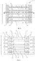
- Figure 2 is a cross-section taken through an actuator component 101 of a droplet deposition head according to a first example embodiment.
- the actuator component of the first example embodiment is a modification of the initial design of an actuator component detailed above with reference to Figures 1A-1C .
- the actuator component 101 of the first example embodiment should be understood as having generally the same structure and functionality as the actuator component 1 of the initial design shown in Figures 1A-1C , except where stated below.
- Like features are indicated using the same reference numerals as Figures 1A-1C , but with an increment of 100.
- the actuator component 101 of the first example embodiment includes a plurality of patterned layers that are stacked in a layering direction L, which extends into the page in Figure 2 .
- a row of fluid chambers 110, a row of inlet passageways 112 and a row of outlet passageways 116 are formed within the layers of the actuator component 101, with each of these rows extending in row direction R, which is perpendicular to the layering direction L.
- Figure 2 The cross-section of Figure 2 is taken through the fluid chamber substrate layer 202 of the actuator component 101 and shows the relative locations of fluid chambers 110, inlet passageways 112, and outlet passageways 116.
- the row of inlet passageways 112 is staggered, with a number of the inlet passageways 112 being offset from their neighbours in an inlet passageway offset direction D i .
- the row of outlet passageways 116 is similarly staggered, with a number of the outlet passageways 116 being offset from their neighbours in an outlet passageway offset direction D o .
- the row of fluid chambers 110 is also staggered, with a number of the fluid chambers 110 being offset from their neighbours in a chamber offset direction D c .
- each nozzle 118 with respect to its corresponding chamber 110 has substantially the same shape and that the position of each nozzle 118 with respect to its corresponding chamber 110 is substantially the same for all chambers. As is apparent from Figure 2 , this may, in certain embodiments, result in the corresponding row of nozzles 118 being staggered in substantially the same manner as the row of fluid chambers 110.
- the offset direction for the row of nozzles 118 may be the same as the offset direction D c for the row of fluid chambers 110.
- the offset direction for the row of nozzles 118 is perpendicular to the direction in which the nozzles eject droplets (into the page in Figure 2 ).
- inlet passageways 112 are assigned alternately to group “a” (such passageways being indicated in the drawing by 112a) and to group “b” (such passageways being indicated in the drawing by 112b), with inlet passageways within a particular group 112a, 112b being aligned in the inlet passageway offset direction D i .
- outlet passageways 116 are assigned to the same groups "a” and "b", as are the fluid chambers 110 (with membership of a group being indicated by the suffix "a” or "b"). Outlet passageways within a particular group 116a, 116b are aligned in the outlet passageway offset direction D o .
- inlet passageways 212 and outlet passageways 216 corresponding to the same chamber 210 are assigned to the same one of groups "a" and "b".
- each inlet passageway 112 is elongate in a direction that is generally parallel to the layering direction L, as is each outlet passageway 116.
- the inlet passageway offset direction D i is perpendicular to the length direction of each inlet passageway 112. Consequently, the inlet passageway offset direction D i in Figure 2 is perpendicular to both the row direction R and the layering direction L.
- outlet passageway offset direction D o is similarly perpendicular to the length direction of each outlet passageway 116. Consequently, the outlet passageway offset direction D o in Figure 2 is perpendicular to both the row direction R and the layering direction L.
- each inlet passageway 112 is fluidically connected so as to supply fluid to a respective one of the row of fluid chambers 110.
- each outlet passageway 116 is fluidically connected so as to receive fluid from a respective one of the row of fluid chambers 110.
- each of the inlet passageways 112 may open to the exterior of the actuator component 101, so that the inlet passageway 112 in question may receive fluid from exterior the actuator component (e.g. from a manifold component attached to the actuator component 101 that forms part of the droplet deposition head), and convey it towards the fluid chambers 110.
- An end of each of the outlet passageways 116 may similarly open to the exterior of the actuator component 101 so that the outlet passageway 116 in question may convey fluid that it has received from the chambers 110 to exterior the actuator component 101 (e.g. to the same or an additional manifold component attached to the actuator component 101 that forms part of the droplet deposition head).
- the actuator component 101 may include inlet and outlet ports, as described above with reference to Figure 1D with these respectively receiving fluid from and conveying fluid to the exterior of the actuator component 101.
- Such inlet and outlet ports may have sufficient width perpendicular to the row direction R (and to layering direction L) to account for the staggering of the inlet passageways 112 and outlet passageways 116, or may be shaped so as correspond to the staggering of the inlet passageways 112 and outlet passageways 116, for example having a zig-zag or serpentine shape.
- the Applicant has carried out computational modelling on alternative actuator component designs that have a manifold chamber in close proximity to the chambers 110.
- Such modelling indicates pressure waves within the droplet fluid can transfer significant amounts of energy from an actuated chamber to its neighbours. This transferred energy may interfere with droplet ejection from the neighbouring chambers, in a process known as "crosstalk".
- Such crosstalk may, for example, result in greater variability of the velocity (in terms of magnitude and/or direction) and/or the volume of the droplets ejected by the head, owing to such interference between neighbouring chambers.
- actuator component designs such as that shown in Figure 2 , which have individual inlet and/or outlet passageways 112/116 for each chamber that may guide the residual energy away from the chambers 110 being actuated, may experience less interference or crosstalk between neighbouring chambers. This is found to be particularly the case where the length of each inlet and/or outlet passageway 112/116 is at least 100 ⁇ m, with further benefit potentially being provided where the length of each inlet and/or outlet passageway 112/116 is at least 200 ⁇ m.
- actuator component 1 illustrated in Figures 1A-1C may experience a transfer of significant amounts of energy from pressure waves within an inlet (or outlet) passageway (which originate from pressure waves within the fluid chamber) to a neighbouring inlet (or outlet) passageway, by means of lateral movement of the wall 13, 17 dividing those passageways.
- Such lateral movement of the dividing wall 13, 17 generates pressure waves in the fluid within the neighbouring inlet (or outlet) passageway, which may then be transferred to the fluid chamber to which it is connected.
- crosstalk remains an issue to some extent in the actuator component design illustrated in Figures 1A-1C .
- the actuator component of Figure 2 addresses the crosstalk issues in a different manner. Specifically, by staggering the rows of inlet and outlet passageways 112, 116, there is less overlap between neighbouring inlet passageways and neighbouring outlet passageways, which results in structural vibrations within the actuator component meeting significantly greater resistance when travelling through the walls 113, 117 between neighbouring passageways. Put differently, the walls 113, 117 are structurally stiffer.
- each actuator component was operated such that a particular chamber was actuated, firstly, to eject a droplet when one of its two neighbouring chambers simultaneously ejects a droplet and, secondly, to eject a droplet when neither of the neighbouring chambers simultaneously ejects a droplet.
- the velocities of the droplets ejected by the particular chamber in the two cases were then compared, so as to provide a measure of the crosstalk between the particular chamber and its neighbouring chambers.
- the row of fluid chambers 110 is staggered. This reduces the portion I w of the length of the wall 111 where neighbouring chambers 110 overlap.
- this portion I w of the length of the wall 111 where neighbouring chambers 110 overlap is, in consequence, less than the length of the chambers 110.
- the length I w of the overlap portion of the wall 111 may be less than the acoustic length I a of the chambers 110. Accordingly, this may contribute to reducing crosstalk in the actuator component 101.
- the overlap portion I w of the wall 111 is not aligned with the centre of the neighbouring chamber 110.
- the fundamental mode of vibration of the wall of a chamber will be at or near the centre of the chamber. Accordingly, a possible consequence of the overlap portion I w of the wall 111 not being aligned with the centre of the neighbouring chamber is that vibrations are less efficiently transferred from one chamber 110 through this overlap portion of the wall 111 to its neighbour and/or have less effect on ejection where they are transferred. Accordingly, this may contribute to reducing crosstalk in the actuator component 101.
- the row of nozzles 118 is staggered.
- the actuation of fluid chambers 110 belonging to different groups may take place at different times: there may be a temporal offset of the actuation of different groups. This may, for example, result in the droplets ejected by the different groups of chambers 110a, 110b forming dots disposed on a single line on the substrate, despite the staggering of the row of nozzles 118.
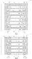
- Figure 3 illustrates in a similar manner to Figure 2 an actuator component 201 according to such an embodiment.
- the same reference numerals are used as in Figures 1A-1C , but with an increment of 200.
- the actuator component 201 of Figure 3 includes a staggered row of inlet passageways 212 and a staggered row of outlet passageways 216, but a linearly-aligned row of fluid chambers 210; specifically, the fluid chambers 210 are aligned along a line extending in the row direction R.
- the nozzles 218 for the chambers 210 are likewise aligned along a line extending in the row direction R.
- the inlet passageways 212 are assigned alternately to group “a” (such passageways being indicated in the drawing by 212a) and to group “b” (such passageways being indicated in the drawing by 212b), with inlet passageways within a particular group 212a, 212b being aligned in the inlet passageway offset direction D i .
- the outlet passageways 216 are assigned to the same groups "a” and “b” (with membership of a group being indicated by the suffix "a” or "b”, as before), with outlet passageways within a particular group 216a, 216b being aligned in the outlet passageway offset direction D o .
- Inlet passageways 212 and outlet passageways 216 corresponding to the same chamber 210 are assigned to the same one of groups "a” and "b”.
- the flow restrictor passages 214 for adjacent passageways are not of equal length.
- other characteristics of the flow restrictor passages 214 are varied so that the flow restrictor passages 214 nonetheless provide the same resistance and inertance.
- their cross-sectional areas may be varied e.g. by altering their widths and/or heights.
- each of the inlet passageways 212 and outlet passageways 216 may open to the exterior of the actuator component 201, so as to respectively receive fluid from and convey fluid to exterior the actuator component.
- the actuator component 201 may include inlet and outlet ports, as described above with reference to Figure 1D with these respectively receiving fluid from and conveying fluid to the exterior of the actuator component 201.
- such inlet and outlet ports may have sufficient width perpendicular to the row direction R (and to layering direction L) to account for the staggering of the rows of inlet passageways 212 and outlet passageways 216, or may be shaped so as correspond to the staggering of the rows of inlet passageways 212 and outlet passageways 216, for example having a zig-zag or serpentine shape.
- chambers 210 and nozzles 218 are illustrated as being aligned in like manner, in other embodiments the row of nozzles could be staggered, with the row of chambers being aligned.
- Figure 4 illustrates in a similar manner to Figures 2 and 3 an actuator component 301 according to such an embodiment, in which three groups are utilised.
- Figure 4 the same reference numerals are used as in Figures 1A-1C , but with an increment of 300.
- inlet passageways 312, outlet passageways 316, and fluid chambers 310 are all staggered.
- all of the fluid chambers 310 have substantially the same shape, that the position of each nozzle 318 with respect to its corresponding chamber 310 is substantially the same for all chambers.
- the row of nozzles 318 is staggered in substantially the same manner as the row of fluid chambers 310, having the same offset direction as the row of fluid chambers 310 (namely, chamber offset direction D c ).
- each of the inlet passageways 312 and outlet passageways 316 may open to the exterior of the actuator component 301, so as to respectively receive fluid from and convey fluid to exterior the actuator component.
- the actuator component 301 may include inlet and outlet ports, as described above with reference to Figure 1D with these respectively receiving fluid from and conveying fluid to the exterior of the actuator component 301.
- such inlet and outlet ports may have sufficient width perpendicular to the row direction R (and to layering direction L) to account for the staggering of the rows of inlet passageways 312 and outlet passageways 316, or may be shaped so as correspond to the staggering of the rows of inlet passageways 312 and outlet passageways 316, for example having a zig-zag or serpentine shape.
- Figure 5 is a plan view of a cross-section in plane through fluid chamber substrate layer 402, it is apparent that, as with the example embodiment of Figure 3 , there is provided a staggered row of inlet passageways 412 and a staggered row of outlet passageways 416, but a linearly-aligned row of fluid chambers 410 (the fluid chambers 410 being aligned along a line extending in the row direction R).
- the nozzles 418 for the chambers 410 are likewise aligned along a line extending in the row direction R.
- the inlet passageways 412 are assigned alternately to group “a” (such passageways being indicated in the drawing by 412a) and to group “b” (such passageways being indicated in the drawing by 412b), with inlet passageways within a particular group 412a, 412b being aligned in the inlet passageway offset direction D i .
- the outlet passageways 416 are assigned to the same groups "a” and “b” (with membership of a group being indicated by the suffix "a” or “b”, as before), with outlet passageways within a particular group 416a, 416b being aligned in the outlet passageway offset direction D o .
- Inlet passageways 412 and outlet passageways 416 corresponding to the same chamber 410 are assigned to the same one of groups "a" and "b".
- the inlet passageway offset direction D i in Figures 5A and 5B is opposite to the outlet passageway offset direction D o .
- the arrangement of the inlet passageways 412 is essentially symmetric with the arrangement of the outlet passageways 416 about an axis extending in the row direction R.
- the flow restrictor passages 414 for adjacent passageways are not of equal length.
- other characteristics of the flow restrictor passages 414 are varied, such as their cross-sectional areas (e.g. by altering their widths and/or heights).
- each of the inlet passageways 412 and outlet passageways 416 may open to the exterior of the actuator component 401, so as to respectively receive fluid from and convey fluid to exterior the actuator component.
- the actuator component 401 may include inlet and outlet ports, as described above with reference to Figure 1D with these respectively receiving fluid from and conveying fluid to the exterior of the actuator component 401.
- such inlet and outlet ports may have sufficient width perpendicular to the row direction R (and to layering direction L) to account for the staggering of the rows of inlet passageways 412 and outlet passageways 416, or may be shaped so as correspond to the staggering of the rows of the inlet passageways 412 and outlet passageways 416, for example having a zig-zag or serpentine shape.
- chambers 410 and nozzles 418 are illustrated as being aligned in like manner, in other embodiments the row of nozzles could be staggered, with the row of chambers being aligned.
- Figure 6A illustrates in a similar manner to Figures 1A and 5A an actuator component 501 according to such an embodiment.
- Figures 6A and 6B the same reference numerals are used as in Figures 1A-1C , but with an increment of 500.
- the actuator component 501 includes a number of patterned layers that are stacked in layering direction L, with each layer extending in a plane perpendicular to this layering direction L.
- the patterned layers include nozzle layer 504, fluid chamber substrate layer 502, membrane layer 520, wiring and passivation layers 530, and capping layer 540 (in that order).
- FIG. 6B which is a cross-section taken in plane 6B indicated in Figure 6A through fluid chamber substrate layer 502, a row of fluid chambers 510 and a row of inlet passageways 512 is formed within the layers of the actuator component 501, with these rows extending in a row direction R, which is substantially perpendicular to the layering direction.
- each inlet passageway 512 is fluidically connected so as to supply fluid to one end of a respective one of the row of fluid chambers 510. Specifically, each inlet passageway 512 supplies fluid to the end in question of the corresponding fluid chamber 510 via a respective flow restrictor passage 514.
- a nozzle for the chamber 518 is located near the opposing end of the chamber 510.
- the chamber 510 is elongate with the nozzle being located near one longitudinal end and the inlet passageway being fluidically connected to the opposite longitudinal end.
- each inlet passageway 512 is elongate in the layering direction L.
- the inlet passageway 512 extends through the membrane layer 520 and through wiring and passivation layer 530.
- both the row of fluid chambers 510 and the row of inlet passageways 512 are staggered: a number of the fluid chambers 510 are offset from their neighbours in a chamber offset direction D c whereas a number of the inlet passageways 512 are offset from their neighbours in an inlet passageway offset direction D i .
- all of the fluid chambers 510 have substantially the same shape, that the position of each nozzle 518 with respect to its corresponding chamber 510 is substantially the same for all chambers.
- the row of nozzles 518 is staggered in substantially the same manner as the row of fluid chambers 510, having the same offset direction as the row of fluid chambers 510 (namely, chamber offset direction D c ).
- the inlet passageways 512 are assigned alternately to group “a” (such passageways being indicated in the drawing by 512a) and to group “b” (such passageways being indicated in the drawing by 512b), with inlet passageways within a particular group 512a, 512b being aligned in the inlet passageway offset direction D i .
- the fluid chambers 510 are assigned to the same groups “a” and “b” (with membership of a group being indicated by the suffix "a” or "b”, as before).
- each fluid chamber 510 is assigned to the same one of groups "a” and "b” as its corresponding inlet passageway 512.
- each of the inlet passageways 512 may open to the exterior of the actuator component 501, so as to receive fluid from exterior the actuator component.
- the actuator component 501 may include one or more inlet ports, as described above with reference to Figure 1D , with these receiving fluid from the exterior of the actuator component 501.
- such inlet ports may have sufficient width perpendicular to the row direction R (and to layering direction L) to account for the staggering of the row of inlet passageways 412, or may be shaped so as correspond to the staggering of the row of the inlet passageways 412, for example having a zig-zag or serpentine shape.
- FIG. 7A-7C illustrate an actuator component 601 according to such an embodiment.
- the same reference numerals are used as in Figures 1A-1C , but with an increment of 600.
- the actuator component 601 of the example embodiment of Figures 7A-7C is a modification of the example embodiment of Figures 6A-6B and therefore should be understood as having generally the same structure and functionality as the actuator component 501 of that example embodiment, except where stated below.
- the actuator component 601 includes a number of patterned layers that are stacked in layering direction L, with each layer extending in a plane perpendicular to this layering direction L.
- the patterned layers include nozzle layer 604, fluid chamber substrate layer 602, membrane layer 620, wiring and passivation layers 630, and capping layer 640 (in that order).
- each chamber 610 is provided with an inlet passageway 612 only (and not an outlet passageway).
- each inlet passageway 612 is fluidically connected so as to supply fluid to one end of a respective one of the row of fluid chambers 610. Specifically, each inlet passageway 612 supplies fluid to the end in question of the corresponding fluid chamber 610 via a respective flow restrictor passage 614.
- a nozzle 618 for the chamber 610 is located at the opposing end of the chamber 610.
- the chamber 610 is elongate with the nozzle 618 being located at one longitudinal end and the inlet passageway being fluidically connected to the opposite longitudinal end.
- each inlet passageway 612 extends generally parallel to the length of the corresponding one of the fluid chambers 610.
- the row of fluid chambers 610 is linearly-aligned. Specifically, the row of fluid chambers 610 is aligned along a line extending in the row direction R (which is into the page in Figures 7A and 7B ). This is apparent from a comparison of Figure 7A with 7B: while the inlet passageway 612b shown in Figure 7B is offset in layering direction L from the inlet passageway 612a shown in Figure 7A , the corresponding fluid chambers 610 are aligned in layering direction L.
- the inlet passageways 612 are assigned alternately to group “a” (such passageways being indicated in the drawing by 612a) and to group “b” (such passageways being indicated in the drawing by 612b), with inlet passageways within a particular group 612a, 612b being aligned in the inlet passageway offset direction, which is layering direction L.
- the inlet passageways 612 assigned to a particular group are formed in a respective, distinct subset of the layers.
- the subset of layers in which the inlet passageways 612a assigned to group "a" are formed is distinct from the subset of layers in which the inlet passageways 612b of group "b" are formed.
- the inlet passageways 612a belonging to group "a" are provided within fluid chamber substrate layer 602, where they extend parallel to membrane layer 620 (and perpendicular to row direction R, which is into the page in Figure 7A ).
- the inlet passageways 612b belonging to group "b" are provided substantially within capping layer 640, where they extend parallel to membrane layer 620 (and perpendicular to row direction R, which is into the page in Figure 7B ). As may also be seen from Figure 7B , each of the inlet passageways 612b of group “b” extends at one end through membrane layer 620 so as to connect with the corresponding one of the flow restrictor passages 614.
- Figure 7C is a plan view of the actuator component 601 from the side to which the capping layer 640 is attached, with the capping layer 640 removed so as to show clearly an illustrative configuration of the electrical traces 632 on membrane layer 620.
- Figure 7C the fluid chambers 610, flow restrictor passages 614 and nozzles 618, which are located on the far side of the membrane 620 in the view of Figure 7C , are depicted with dashed lines so as show clearly their orientations relative to the traces 632, inlet passageways 612 and the actuating elements 622.
- each actuating element 622 is electrically connected to two traces 632.
- the traces 632 extend in a plane having a normal in the layering direction L.
- the two traces 632 for each actuating element 622 originate at opposite ends of the actuating element 622, they both extend in the same direction and towards the same side of the membrane layer 620. This may be contrasted with the initial design of Figure 1C , where the two traces 32 for an actuating element 22 extend in opposite directions towards opposite sides of the membrane layer 20.
- each of the inlet passageways 612 may open to the exterior of the actuator component 601, so as to receive fluid from exterior the actuator component.
- the actuator component 601 may include one or more inlet ports that are similar to those described above with reference to Figure 1D , but which may be provided at the sides of the actuator component with respect to the layering direction L, in contrast to the inlet port 15 shown in Figure 1D .
- inlet ports are provided on the side of the actuator component 601, they may have sufficient width in the layering direction to account for the staggering of the row of inlet passageways 612, or may be shaped so as correspond to the staggering of the row of the inlet passageways 612, for example having a zig-zag or serpentine shape. Regardless of their positioning, such inlet ports are configured to receive fluid from the exterior of the actuator component 601.
- chambers 610 and nozzles 618 are illustrated as being aligned in like manner, in other embodiments the row of nozzles could be staggered, with the row of chambers being aligned.
- Figures 8A-8C illustrate a further example embodiment with staggered rows whose offset directions D ⁇ , D o are parallel to the layering direction L, as in the example embodiment of Figures 7A-7C ; however, in contrast to the example embodiment of Figures 7A-7C , in the example embodiment of Figures 8A-8C there is both an inlet passageway 712 and an outlet passageway 716 for each chamber 710 (for example to enable the actuator component 701 to be incorporated in a droplet deposition head configured for use in a recirculation mode).
- the actuator component 701 includes a number of patterned layers that are stacked in layering direction L, with each layer extending in a plane perpendicular to this layering direction L.
- a row of fluid chambers 710, a row of inlet passageways 712 and a row of outlet passageways 716 are formed within the layers of the actuator component 701, with each of these rows extending in row direction R, which is perpendicular to the layering direction L.
- the patterned layers include nozzle layer 704, fluid chamber substrate layer 702, membrane layer 720, wiring and passivation layers, and capping layer 740 (in that order).
- the row of inlet passageways 712 is staggered, with a number of the inlet passageways 712 being offset from their neighbours in an inlet passageway offset direction D ⁇ , which is the same as the layering direction L.
- the row of outlet passageways 716 is similarly staggered, with a number of the outlet passageways 716 being offset from their neighbours in an outlet passageway offset direction D o , which again is the same as the layering direction L.
- the inlet passageways 712 are assigned alternately to group “a” (such passageways being indicated in the drawing by 712a) and to group “b” (such passageways being indicated in the drawing by 712b), with inlet passageways within a particular group 712a, 712b being aligned in the inlet passageway offset direction D i .
- the outlet passageways 716 are assigned to the same groups "a” and “b” (with membership of a group being indicated by the suffix "a” or “b”, as before), with outlet passageways within a particular group 716a, 716b being aligned in the outlet passageway offset direction D o .
- Inlet passageways 712 and outlet passageways 716 corresponding to the same chamber 710 are assigned to the same one of groups "a” and "b".
- the inlet passageways 712 and outlet passageways 716 assigned to a particular group are formed in a respective, distinct subset of the layers.
- the subset of layers in which the inlet and outlet passageways 712a, 716a of group "a" are formed is distinct from the subset of layers in which the inlet and outlet passageways 712b, 716b of group "b" are formed.
- the inlet passageways 712a belonging to group "a" are provided within fluid chamber substrate layer 702, where they extend parallel to membrane layer 720 (and perpendicular to row direction R, which is into the page in Figure 8A ).
- the outlet passageways 716a belonging to group “a” are similarly provided within fluid chamber substrate layer 702 and also extend parallel to membrane layer 720.
- the inlet passageways 712b belonging to group “b” are provided substantially within capping layer 740, where they extend parallel to membrane layer 720 (and perpendicular to row direction R, which is into the page in Figure 8B ).
- the inlet passageways 712b belonging to group “b” are therefore defined between the membrane layer 720 and the capping layer 740.
- each of the inlet passageways 712b of group “b” extends at one end through membrane layer 720 so as to connect with the corresponding one of the flow restrictor passages 714a.
- the outlet passageways 716b belonging to group “b” are similarly provided substantially within capping layer 740 and similarly extend parallel to membrane layer 720 (and perpendicular to row direction R, which is into the page in Figure 8B ).
- the outlet passageways 716b belonging to group “b” are therefore defined between the membrane layer 720 and the capping layer 740.
- each of the outlet passageways 716b of group “b” extends at one end through membrane layer 720 so as to connect with the corresponding one of the flow restrictor passages 714b.
- Figure 8C is a plan view of the actuator component 701 from the side to which the capping layer 740 is attached, with the capping layer 740 removed so as to show clearly an illustrative configuration of electrical traces 732 on membrane layer 720.
- Figure 8C the fluid chambers 710, flow restrictor passages 714a, 714b and nozzles 718, which are located on the far side of the membrane 720 in the view of Figure 8C , are depicted with dashed lines so as show clearly their orientations relative to the traces 732, inlet passageways 712, outlet passageways 716 and the actuating elements 722.
- each actuating element 722 is electrically connected to two traces 732.
- the traces 732 extend in a plane having a normal in the layering direction L.
- the inlet passageways 712b of group “b” cross this plane, with each such inlet passageway 712b passing between conductive traces 732.
- one trace passes between each pair of neighbouring inlet passageways 712 in group “b” (as the trace in question passes from one side of the row of inlet passageways 712 to the other).
- the outlet passageways 716b in group “b” likewise cross this plane, with each outlet passageway 716b in group “b” passing between conductive traces 732.
- one trace passes between each pair of neighbouring outlet passageways 716b in group "b” (as the trace in question passes from one side of the row of outlet passageways 716 to the other).
- the two traces 732 for each actuating element 722 originate at opposite ends of the actuating element 722 and extend in opposite directions towards opposite sides of the membrane layer 20, where bond pads may be provided for electrical connection to drive circuitry.
- bond pads may be provided for electrical connection to drive circuitry.
- traces 732 for neighbouring chambers 710 are routed such that they overlie, in layering direction L, either an inlet passageway 712a or an outlet passageway 716a in group "a". This may reduce the potential for traces 732 to be exposed to fluid within the inlet passageways 712b or outlet passageways 716b in group "b", which, as noted above, are defined between the membrane layer 720 - on which the traces 732 are provided - and the capping layer 740.
- each of the inlet passageways 712 and outlet passageways 716 may open to the exterior of the actuator component 701, so as to respectively receive fluid from and convey fluid to exterior the actuator component.
- the actuator component 701 may include inlet and outlet ports that are similar to those described above with reference to Figure 1D , but which may be provided at the sides of the actuator component 701 with respect to the layering direction L, in contrast to the inlet port 15 and outlet port 19 shown in Figure 1D .
- the inlet and/or outlet ports are provided on the side of the actuator component 701, they may have sufficient width in the layering direction L to account for the staggering of the rows of inlet passageways 712 and outlet passageways 716, or may be shaped so as correspond to the staggering of the rows of the inlet passageways 712 and outlet passageways 716, for example having a zig- zag or serpentine shape.
- such inlet and outlet ports are respectively configured to receive fluid from and convey fluid to the exterior of the actuator component 701.
- chambers 710 and nozzles 718 are illustrated as being aligned in like manner, in other embodiments the row of nozzles could be staggered, with the row of chambers being aligned.
- the inlet passageways and outlet passageways are depicted as having rectangular cross-sections, it should be understood that the cross-section (specifically the cross-section taken perpendicular to the length of an inlet/outlet passageway) may take a variety of shapes.
- the cross-section may be triangular shaped, square shaped, rectangular shaped, pentagonal shaped, hexagonal shaped, rhombus shaped, oval shaped or circular shaped.
- cross-sections may be shaped so as to have symmetry about an axis parallel to the row direction R. Examples of such cross-sections are illustrated in Figures 9A-9C .
- FIG 9A shows an example where the inlet passageways 812 have been assigned to two offset groups, group "a” and group "b", as described above with reference to Figures 2, 3 , 5 , 6 , 7 and 8 .
- the cross-sectional shape of each inlet passageway from the first group 812a is symmetric with that of each inlet passageway from the second group 812b about an axis parallel to the row direction R.
- the amount of wall 813 separating adjacent inlet passageways 812a, 812b is increased, as compared with inlet passageways having rectangular cross-sections.
- Figure 9B shows a further example where the inlet passageways 912 have been likewise assigned to two offset groups, group "a" and group "b".
- the cross-sectional shape of each inlet passageway from the first group 912a is not only symmetric with that of each inlet passageway from the second group 912b about an axis parallel to the row direction R, but is also self-symmetric about such an axis.
- the amount of wall 913 separating adjacent inlet passageways 912a, 912b is again increased, as compared with inlet passageways having rectangular cross-sections, such as those shown in Figure 2 .
- Figure 9C shows an example in which the inlet passageways 1012 have been cyclically assigned to three offset groups, group “a”, group “b”, and group “c".
- the cross-sectional shape of each inlet passageway is self-symmetric about an axis parallel to the row direction R.
- the amount of wall 1013 separating adjacent inlet passageways 1012a, 1012b from groups “a” and “b” is increased, as is the amount of wall 1013 separating adjacent inlet passageways 1012b, 1012c from groups “b” and “c”, as compared with inlet passageways having rectangular cross-sections.
- Figures 10A-10C illustrate still further examples of suitable self-symmetric cross-sectional shapes for the fluid inlet and/or outlet passageways. Specifically, Figures 10A-10C show, respectively, a rectangular-shaped cross-section, a (truncated) rhombus-shaped cross-section, and a stadium-shaped cross-section.
- Figures 11A-11C then illustrate modifications to the cross-sectional shapes shown in Figures 10A-10C respectively. More particularly, Figures 11A-11C illustrate the inclusion of an additional wall portion 50a, 50b on each longitudinal side of the cross-sectional shape. The inclusion of each such additional portion 50a, 50b is equivalent to the inclusion of a strengthening rib on either side of the inlet passageway's length, each strengthening rib extending parallel to the length of the inlet passageway. Such strengthening ribs may further reduce cross-talk between adjacent chambers.
- the members of each staggered row are assigned to the same two or more groups this is by no means essential.
- the inlet passageways could, for example, be assigned to three groups, with the outlet passageways being assigned to only two groups.
- the inlet passageways and the outlet passageways could be assigned to the same number of groups (e.g. three), but with these groups being specific to the staggered row in question.
- the actuator components described above with reference to Figures 2-8 may, for example, be fabricated using processes typically used to fabricate structures for Micro-Electro-Mechanical Systems (MEMS).
- MEMS Micro-Electro-Mechanical Systems
- the actuator components may be described as being MEMS actuator components (it being noted that this carries with it no implication as to the type of actuating element utilised: for instance, actuator components with thermal actuating elements are referred to within the art as MEMS actuator components regardless of the fact that they do not include electromechanical actuating elements).
Landscapes
- Particle Formation And Scattering Control In Inkjet Printers (AREA)
- Coating Apparatus (AREA)
- Ink Jet (AREA)
- Micromachines (AREA)
- Organic Low-Molecular-Weight Compounds And Preparation Thereof (AREA)
Claims (15)
- Aktorkomponente (1'; 101; 201; 301; 401; 701) für einen Tröpfchenabscheidekopf, die Folgendes umfasst:mehrere strukturierte Schichten, wobei jede Schicht in einer Ebene mit einer in einer Schichtrichtung (L) verlaufenden Normalen verläuft, wobei die Schichten in Schichtrichtung (L) aufeinandergestapelt sind,eine Reihe von Fluidkammern (10; 110; 210; 310; 410; 710), die in den mehreren Schichten ausgebildet sind, wobei die Reihe in einer Reihenrichtung (R) verläuft, die im Wesentlichen senkrecht zur Schichtrichtung (L) verläuft, wobei jede Fluidkammer (10; 110; 210; 310; 410; 710) mit einer entsprechenden Düse (18; 118; 218; 318; 418; 718) und einem entsprechenden Betätigungselement (22; 122; 222; 322; 422; 722) versehen ist, das zum Bewirken des Ausstoßens von Fluid aus der betreffenden Kammer durch die zugehörige Düse (18; 118; 218; 318; 418; 718) betätigbar ist,eine Reihe Einlassdurchgänge (12; 112; 212; 312; 412; 712), die in den mehreren Schichten ausgebildet sind, wobei die Reihe in Reihenrichtung (R) verläuft, wobei jeder Einlassdurchgang (12; 112; 212; 312; 412; 712) fluidverbunden ist und so einer entsprechenden Fluidkammer (10; 110; 210; 310; 410; 710) Fluid zuführt, und:a) eine Reihe Auslassdurchgänge (16; 116; 216; 316; 416; 716), die in den mehreren Schichten ausgebildet sind, wobei die Reihe in Reihenrichtung (R) verläuft, wobei jeder Auslassdurchgang (16; 116; 216; 316; 416; 716) fluidverbunden ist und so Fluid aus einer entsprechenden Fluidkammer (10; 110; 210; 310; 410; 710) aufnimmt, oderb) eine zweite Reihe Einlassdurchgänge (16; 116; 216; 316; 416; 716), die in den mehreren Schichten ausgebildet sind, wobei die Reihe in Reihenrichtung (R) verläuft, wobei jeder Einlassdurchgang (16; 116; 216; 316; 416; 716) fluidverbunden ist und so einer entsprechenden Fluidkammer (10; 110; 210; 310; 410; 710) Fluid zuführt,wobei die Reihe oder die Reihen Einlassdurchgänge (12; 16; 112; 116; 212; 216; 312; 316; 412; 416; 712; 716) und/oder die Reihe Auslassdurchgänge (16; 116; 216; 316; 416; 716) verschoben angeordnet ist/sind, wodurch zumindest einige der Elemente der betreffenden verschoben angeordneten Reihe in einer Versatzrichtung (Di, Do), die senkrecht zur Reihenrichtung (R) verläuft, für die betreffende verschoben angeordnete Reihe zu ihren Nachbarn versetzt sind.
- Aktorkomponente nach Anspruch 1, wobei die Reihe Fluidkammern (10; 110; 210; 310; 410; 710) verschoben angeordnet ist, wodurch zumindest einige der Kammern (10; 110; 210; 310; 410; 710) der Reihe in einer Versatzrichtung für die Reihe Fluidkammern (10; 110; 210; 310; 410; 710), die senkrecht zu der Reihenrichtung (R) verläuft, zu ihren Nachbarn versetzt sind.
- Aktorkomponente nach Anspruch 1 oder 2, die ferner einen oder mehrere Einlasskanäle (15) umfasst, die in den Schichten ausgebildet sind, wobei der oder jeder Einlasskanal (15) an einem ersten Ende mit der Außenseite der mehreren Schichten fluidverbunden ist und so von dort Fluid aufnimmt und an einem zweiten Ende mit einer Anzahl Einlassdurchgänge (12; 112; 212; 312; 412; 712) in der Reihe fluidverbunden ist und diesen so Fluid zuführt.
- Aktorkomponente nach Anspruch 3, wobei der oder jeder Einlasskanal (15) in Reihenrichtung (R) langgestreckt ist.
- Aktorkomponente nach einem der vorhergehenden Ansprüche, die ferner einen oder mehrere Auslasskanäle (19) umfasst, die in den Schichten ausgebildet sind, wobei der oder jeder Auslasskanal (19) an einem ersten Ende mit einer Anzahl Auslassdurchgänge (16; 116; 216; 316; 416; 716) in der Reihe fluidverbunden ist und so von dort Fluid aufnimmt und an einem zweiten Ende mit der Außenseite der mehreren Schichten fluidverbunden ist und dieser so Fluid zuführt.
- Aktorkomponente nach Anspruch 5, wobei der oder jeder Auslasskanal (19) in Reihenrichtung (R) langgestreckt ist.
- Aktorkomponente nach einem der vorhergehenden Ansprüche, wobei die Elemente jeder der verschoben angeordneten Reihen gemäß einem sich wiederholenden Muster der betreffenden verschoben angeordneten Reihe entsprechend zwei oder mehr Gruppen zugeordnet sind und
wobei für jede verschoben angeordnete Reihe Elemente in der gleichen Gruppe in Versatzrichtung für die betreffende verschoben angeordnete Reihe ausgerichtet und Elemente in unterschiedlichen Gruppen für die betreffende verschoben angeordnete Reihe um einen Abstand in Versatzrichtung versetzt sind. - Aktorkomponente nach Anspruch 7, wobei die Elemente jeder Gruppe in einer Teilmenge der Schichten ausgebildet sind und sich bei mindestens einer der verschoben angeordneten Reihen die Teilmenge Schichten für eine Gruppe dieser Reihe von der Teilmenge Schichten für eine andere Gruppe dieser Reihe unterscheidet.
- Aktorkomponente nach einem der vorhergehenden Ansprüche, wobei jeder der Einlassdurchgänge (12; 112; 212; 312; 412; 712) in einer Einlassdurchgangslängenrichtung langgestreckt ist,
wobei die Einlassdurchgangslängenrichtung senkrecht zur Schichtrichtung (L) verläuft,
wobei jeder Einlassdurchgang (12; 112; 212; 312; 412; 712) durch eine zugehörige Einlassdurchgangswand definiert ist und
wobei für zumindest eine Gruppe der Einlassdurchgänge (12; 112; 212; 312; 412; 712) jede Einlassdurchgangswand mindestens eine Verstärkungsrippe (50) aufweist, die allgemein parallel zur Einlassdurchgangslängenrichtung verläuft. - Aktorkomponente nach einem der Ansprüche 1 bis 8, wobei jeder der Einlassdurchgänge (12; 112; 212; 312; 412; 712) in Einlassdurchgangslängenrichtung langgestreckt ist,
wobei die Einlassdurchgangslängenrichtung allgemein parallel zur Schichtrichtung verläuft,
wobei jeder Einlassdurchgang (12; 112; 212; 312; 412; 712) durch eine zugehörige Einlassdurchgangswand definiert ist und
wobei für zumindest eine Gruppe der Einlassdurchgänge (12; 112; 212; 312; 412; 712) jede Einlassdurchgangswand mindestens eine Verstärkungsrippe (50) aufweist, die allgemein parallel zur Einlassdurchgangslängenrichtung verläuft. - Aktorkomponente nach einem der vorhergehenden Ansprüche, wobei jeder der Auslassdurchgänge (16; 116; 216; 316; 416; 716) in Auslassdurchgangslängenrichtung langgestreckt ist,
wobei die Auslassdurchgangslängenrichtung senkrecht zur Schichtrichtung verläuft,
wobei jeder Auslassdurchgang (16; 116; 216; 316; 416; 716) durch eine zugehörige Auslassdurchgangswand definiert ist und
wobei für zumindest eine Gruppe der Auslassdurchgänge (16; 116; 216; 316; 416; 716) jede Auslassdurchgangswand mindestens eine Verstärkungsrippe (50) aufweist, die allgemein parallel zur Auslassdurchgangslängenrichtung verläuft. - Aktorkomponente nach einem der Ansprüche 1 bis 10, wobei jeder der Auslassdurchgänge (16; 116; 216; 316; 416; 716) in Auslassdurchgangslängenrichtung langgestreckt ist,
wobei die Auslassdurchgangslängenrichtung allgemein parallel zur Schichtrichtung verläuft,
wobei jeder Auslassdurchgang (16; 116; 216; 316; 416; 716) durch eine zugehörige Auslassdurchgangswand definiert ist und
wobei für zumindest eine Gruppe der Auslassdurchgänge (16; 116; 216; 316; 416; 716) jede Auslassdurchgangswand mindestens eine Verstärkungsrippe (50) aufweist, die allgemein parallel zur Auslassdurchgangslängenrichtung verläuft. - Aktorkomponente nach einem der Ansprüche 9 bis 12, wobei für jeden Einlassdurchgang (12; 112; 212; 312; 412; 712) und/oder Auslassdurchgang (16; 116; 216; 316; 416; 716) mit Verstärkungsrippen (50) die Verstärkungsrippen (50) paarweise angeordnet sind, wobei sich die Elemente jedes Paars auf gegenüberliegenden Seiten des betreffenden Einlassdurchgangs und/oder Auslassdurchgangs befinden.
- Aktorkomponente nach einem der vorhergehenden Ansprüche, die ferner mehrere Leiterbahnen (32; 732) umfasst, welche in einer Ebene verlaufen, die eine Normalen in Schichtrichtung aufweist, und an einer der mehreren Schichten vorgesehen sind, wobei die Leiterbahnen (32; 732) zumindest für einen Teil der elektrischen Verbindung zwischen den Betätigungselementen und Antriebsschaltungen sorgen, und
wobei jede Reihe Einlassdurchgänge (12; 112; 212; 312; 412; 712) und/oder Auslassdurchgänge (16; 116; 216; 316; 416; 716) die Ebene kreuzt, in der die Leiterbahnen (32; 732) vorgesehen sind, und zwischen den Leiterbahnen (32; 732) verläuft. - Tröpfchenabscheidekopf mit der Aktorkomponente nach einem der vorhergehenden Ansprüche.
Applications Claiming Priority (2)
| Application Number | Priority Date | Filing Date | Title |
|---|---|---|---|
| GB1615854.5A GB2562444A (en) | 2016-09-16 | 2016-09-16 | Droplet deposition head and actuator component therefor |
| PCT/GB2016/053103 WO2018051051A1 (en) | 2016-09-16 | 2016-10-05 | Droplet deposition head and actuator component therefor |
Publications (2)
| Publication Number | Publication Date |
|---|---|
| EP3512706A1 EP3512706A1 (de) | 2019-07-24 |
| EP3512706B1 true EP3512706B1 (de) | 2021-06-23 |
Family
ID=57133230
Family Applications (1)
| Application Number | Title | Priority Date | Filing Date |
|---|---|---|---|
| EP16781527.3A Active EP3512706B1 (de) | 2016-09-16 | 2016-10-05 | Tröpfchenabscheidungskopf und aktuatorkomponente dafür |
Country Status (6)
| Country | Link |
|---|---|
| US (1) | US10875302B2 (de) |
| EP (1) | EP3512706B1 (de) |
| JP (1) | JP6949109B2 (de) |
| GB (1) | GB2562444A (de) |
| SG (1) | SG11201901907UA (de) |
| WO (1) | WO2018051051A1 (de) |
Families Citing this family (5)
| Publication number | Priority date | Publication date | Assignee | Title |
|---|---|---|---|---|
| WO2016042165A1 (en) * | 2014-09-18 | 2016-03-24 | Universiteit Gent | Laser ablation probe |
| JP7215196B2 (ja) * | 2019-01-31 | 2023-01-31 | ブラザー工業株式会社 | 液体吐出ヘッド |
| GB2586136B (en) | 2019-08-06 | 2023-01-11 | Xaar Technology Ltd | Nozzle arrangements for droplet ejection devices |
| GB2606721A (en) * | 2021-05-17 | 2022-11-23 | Xaar Technology Ltd | Electrical component |
| CN119590100B (zh) * | 2023-09-11 | 2025-09-30 | 中国科学院苏州纳米技术与纳米仿生研究所 | 微液滴喷射单元以及微液滴喷射装置 |
Family Cites Families (16)
| Publication number | Priority date | Publication date | Assignee | Title |
|---|---|---|---|---|
| JPH09272205A (ja) * | 1996-04-04 | 1997-10-21 | Seiko Epson Corp | 積層型インクジェット式記録ヘッド |
| ATE292562T1 (de) * | 1999-06-30 | 2005-04-15 | Silverbrook Res Pty Ltd | Trägerstruktur und trägeranordnung für einen druckkopf |
| JP4141376B2 (ja) * | 2003-11-12 | 2008-08-27 | セイコーエプソン株式会社 | 液滴吐出装置、マイクロアレイの製造装置及びマイクロアレイの製造方法 |
| JP2006088476A (ja) * | 2004-09-22 | 2006-04-06 | Fuji Photo Film Co Ltd | 液体吐出ヘッド及び画像形成装置 |
| JP2007030361A (ja) * | 2005-07-27 | 2007-02-08 | Fujifilm Holdings Corp | 液体吐出ヘッド及び画像形成装置 |
| JP5302378B2 (ja) * | 2011-01-14 | 2013-10-02 | パナソニック株式会社 | インクジェットヘッド |
| US8596756B2 (en) * | 2011-05-02 | 2013-12-03 | Xerox Corporation | Offset inlets for multicolor printheads |
| JP5782878B2 (ja) | 2011-07-12 | 2015-09-24 | セイコーエプソン株式会社 | 液体噴射ヘッド及び液体噴射装置 |
| JP6187070B2 (ja) * | 2013-09-13 | 2017-08-30 | 株式会社リコー | 液体吐出ヘッド及び画像形成装置 |
| JP2015100947A (ja) * | 2013-11-22 | 2015-06-04 | 株式会社東芝 | 画像形成装置 |
| GB2527804B (en) * | 2014-07-02 | 2016-07-27 | Xaar Technology Ltd | Droplet deposition apparatus |
| JP6410528B2 (ja) * | 2014-08-29 | 2018-10-24 | キヤノン株式会社 | 液体吐出ヘッドとそれを用いたヘッドユニット |
| JP6452352B2 (ja) * | 2014-08-29 | 2019-01-16 | キヤノン株式会社 | 液体吐出ヘッドとその製造方法 |
| JP5933146B1 (ja) * | 2015-03-26 | 2016-06-08 | 京セラ株式会社 | 流路部材、液体吐出ヘッド、記録装置、および流路部材の製造方法 |
| GB2536942B (en) * | 2015-04-01 | 2018-01-10 | Xaar Technology Ltd | Inkjet printhead |
| ITUB20156035A1 (it) * | 2015-11-30 | 2017-05-30 | St Microelectronics Srl | Dispositivo di eiezione di fluido con canale di restringimento, e metodo di fabbricazione dello stesso |
-
2016
- 2016-09-16 GB GB1615854.5A patent/GB2562444A/en not_active Withdrawn
- 2016-10-05 SG SG11201901907UA patent/SG11201901907UA/en unknown
- 2016-10-05 JP JP2019514775A patent/JP6949109B2/ja active Active
- 2016-10-05 EP EP16781527.3A patent/EP3512706B1/de active Active
- 2016-10-05 WO PCT/GB2016/053103 patent/WO2018051051A1/en not_active Ceased
- 2016-10-05 US US16/334,258 patent/US10875302B2/en active Active
Non-Patent Citations (1)
| Title |
|---|
| None * |
Also Published As
| Publication number | Publication date |
|---|---|
| WO2018051051A1 (en) | 2018-03-22 |
| US10875302B2 (en) | 2020-12-29 |
| JP6949109B2 (ja) | 2021-10-13 |
| US20200009866A1 (en) | 2020-01-09 |
| JP2019536654A (ja) | 2019-12-19 |
| EP3512706A1 (de) | 2019-07-24 |
| GB201615854D0 (en) | 2016-11-02 |
| SG11201901907UA (en) | 2019-04-29 |
| GB2562444A (en) | 2018-11-21 |
Similar Documents
| Publication | Publication Date | Title |
|---|---|---|
| EP2451647B1 (de) | Mems-strahlenstruktur für dichte verpackungen | |
| US10532572B2 (en) | Inkjet printhead with staggered fluidic ports | |
| EP1652674B1 (de) | Düsenplatte, Tintenstrahldruckkopf der diese Platte verwendet und dazugehöriges Herstellungsverfahren | |
| US10500854B2 (en) | Droplet deposition head and actuator component therefor | |
| US10875302B2 (en) | Droplet deposition head and actuator component therefor | |
| EP3909775B1 (de) | Piezoelektrische druckvorrichtung mit durchkontaktierungen durch eine piezoelektrische platte | |
| JP2019501041A5 (de) | ||
| EP1815991B1 (de) | Piezoelektrischer Tintenstrahldruckkopf | |
| EP3243664B1 (de) | Durchgangselement, flüssigkeitsausstosskopf damit und aufzeichnungsvorrichtung | |
| WO2018065744A1 (en) | Droplet deposition head | |
| US20200262203A1 (en) | Droplet deposition head and actuator component therefor | |
| JP5163784B2 (ja) | 液滴噴射装置及び液体移送装置 | |
| WO2007117929A2 (en) | Fluid jet print module | |
| JP6267001B2 (ja) | 液体吐出ヘッド、およびそれを用いた記録装置 | |
| EP2516163B1 (de) | Druckkopf | |
| JP6641023B2 (ja) | 液体吐出ヘッド、および記録装置 | |
| KR100802497B1 (ko) | 정전기적으로 기계적 작동되는 유체 정밀 측정 장치 | |
| CN119590100A (zh) | 微液滴喷射单元以及微液滴喷射装置 | |
| JP2007055242A (ja) | 液滴噴射装置及び液体移送装置 | |
| JPWO2018056304A1 (ja) | 液体吐出ヘッド、および記録装置 |
Legal Events
| Date | Code | Title | Description |
|---|---|---|---|
| STAA | Information on the status of an ep patent application or granted ep patent |
Free format text: STATUS: THE INTERNATIONAL PUBLICATION HAS BEEN MADE |
|
| PUAI | Public reference made under article 153(3) epc to a published international application that has entered the european phase |
Free format text: ORIGINAL CODE: 0009012 |
|
| STAA | Information on the status of an ep patent application or granted ep patent |
Free format text: STATUS: REQUEST FOR EXAMINATION WAS MADE |
|
| 17P | Request for examination filed |
Effective date: 20190401 |
|
| AK | Designated contracting states |
Kind code of ref document: A1 Designated state(s): AL AT BE BG CH CY CZ DE DK EE ES FI FR GB GR HR HU IE IS IT LI LT LU LV MC MK MT NL NO PL PT RO RS SE SI SK SM TR |
|
| AX | Request for extension of the european patent |
Extension state: BA ME |
|
| DAV | Request for validation of the european patent (deleted) | ||
| DAX | Request for extension of the european patent (deleted) | ||
| GRAP | Despatch of communication of intention to grant a patent |
Free format text: ORIGINAL CODE: EPIDOSNIGR1 |
|
| STAA | Information on the status of an ep patent application or granted ep patent |
Free format text: STATUS: GRANT OF PATENT IS INTENDED |
|
| INTG | Intention to grant announced |
Effective date: 20210113 |
|
| GRAS | Grant fee paid |
Free format text: ORIGINAL CODE: EPIDOSNIGR3 |
|
| GRAA | (expected) grant |
Free format text: ORIGINAL CODE: 0009210 |
|
| STAA | Information on the status of an ep patent application or granted ep patent |
Free format text: STATUS: THE PATENT HAS BEEN GRANTED |
|
| AK | Designated contracting states |
Kind code of ref document: B1 Designated state(s): AL AT BE BG CH CY CZ DE DK EE ES FI FR GB GR HR HU IE IS IT LI LT LU LV MC MK MT NL NO PL PT RO RS SE SI SK SM TR |
|
| REG | Reference to a national code |
Ref country code: GB Ref legal event code: FG4D |
|
| REG | Reference to a national code |
Ref country code: CH Ref legal event code: EP |
|
| REG | Reference to a national code |
Ref country code: DE Ref legal event code: R096 Ref document number: 602016059690 Country of ref document: DE Ref country code: AT Ref legal event code: REF Ref document number: 1403976 Country of ref document: AT Kind code of ref document: T Effective date: 20210715 |
|
| REG | Reference to a national code |
Ref country code: IE Ref legal event code: FG4D |
|
| RAP4 | Party data changed (patent owner data changed or rights of a patent transferred) |
Owner name: XAAR TECHNOLOGY LIMITED |
|
| REG | Reference to a national code |
Ref country code: LT Ref legal event code: MG9D |
|
| PG25 | Lapsed in a contracting state [announced via postgrant information from national office to epo] |
Ref country code: HR Free format text: LAPSE BECAUSE OF FAILURE TO SUBMIT A TRANSLATION OF THE DESCRIPTION OR TO PAY THE FEE WITHIN THE PRESCRIBED TIME-LIMIT Effective date: 20210623 Ref country code: BG Free format text: LAPSE BECAUSE OF FAILURE TO SUBMIT A TRANSLATION OF THE DESCRIPTION OR TO PAY THE FEE WITHIN THE PRESCRIBED TIME-LIMIT Effective date: 20210923 Ref country code: FI Free format text: LAPSE BECAUSE OF FAILURE TO SUBMIT A TRANSLATION OF THE DESCRIPTION OR TO PAY THE FEE WITHIN THE PRESCRIBED TIME-LIMIT Effective date: 20210623 Ref country code: LT Free format text: LAPSE BECAUSE OF FAILURE TO SUBMIT A TRANSLATION OF THE DESCRIPTION OR TO PAY THE FEE WITHIN THE PRESCRIBED TIME-LIMIT Effective date: 20210623 |
|
| REG | Reference to a national code |
Ref country code: AT Ref legal event code: MK05 Ref document number: 1403976 Country of ref document: AT Kind code of ref document: T Effective date: 20210623 |
|
| PG25 | Lapsed in a contracting state [announced via postgrant information from national office to epo] |
Ref country code: NO Free format text: LAPSE BECAUSE OF FAILURE TO SUBMIT A TRANSLATION OF THE DESCRIPTION OR TO PAY THE FEE WITHIN THE PRESCRIBED TIME-LIMIT Effective date: 20210923 Ref country code: SE Free format text: LAPSE BECAUSE OF FAILURE TO SUBMIT A TRANSLATION OF THE DESCRIPTION OR TO PAY THE FEE WITHIN THE PRESCRIBED TIME-LIMIT Effective date: 20210623 Ref country code: RS Free format text: LAPSE BECAUSE OF FAILURE TO SUBMIT A TRANSLATION OF THE DESCRIPTION OR TO PAY THE FEE WITHIN THE PRESCRIBED TIME-LIMIT Effective date: 20210623 Ref country code: GR Free format text: LAPSE BECAUSE OF FAILURE TO SUBMIT A TRANSLATION OF THE DESCRIPTION OR TO PAY THE FEE WITHIN THE PRESCRIBED TIME-LIMIT Effective date: 20210924 Ref country code: LV Free format text: LAPSE BECAUSE OF FAILURE TO SUBMIT A TRANSLATION OF THE DESCRIPTION OR TO PAY THE FEE WITHIN THE PRESCRIBED TIME-LIMIT Effective date: 20210623 |
|
| REG | Reference to a national code |
Ref country code: NL Ref legal event code: MP Effective date: 20210623 |
|
| RAP4 | Party data changed (patent owner data changed or rights of a patent transferred) |
Owner name: XAAR TECHNOLOGY LIMITED |
|
| PG25 | Lapsed in a contracting state [announced via postgrant information from national office to epo] |
Ref country code: SM Free format text: LAPSE BECAUSE OF FAILURE TO SUBMIT A TRANSLATION OF THE DESCRIPTION OR TO PAY THE FEE WITHIN THE PRESCRIBED TIME-LIMIT Effective date: 20210623 Ref country code: SK Free format text: LAPSE BECAUSE OF FAILURE TO SUBMIT A TRANSLATION OF THE DESCRIPTION OR TO PAY THE FEE WITHIN THE PRESCRIBED TIME-LIMIT Effective date: 20210623 Ref country code: CZ Free format text: LAPSE BECAUSE OF FAILURE TO SUBMIT A TRANSLATION OF THE DESCRIPTION OR TO PAY THE FEE WITHIN THE PRESCRIBED TIME-LIMIT Effective date: 20210623 Ref country code: EE Free format text: LAPSE BECAUSE OF FAILURE TO SUBMIT A TRANSLATION OF THE DESCRIPTION OR TO PAY THE FEE WITHIN THE PRESCRIBED TIME-LIMIT Effective date: 20210623 Ref country code: ES Free format text: LAPSE BECAUSE OF FAILURE TO SUBMIT A TRANSLATION OF THE DESCRIPTION OR TO PAY THE FEE WITHIN THE PRESCRIBED TIME-LIMIT Effective date: 20210623 Ref country code: NL Free format text: LAPSE BECAUSE OF FAILURE TO SUBMIT A TRANSLATION OF THE DESCRIPTION OR TO PAY THE FEE WITHIN THE PRESCRIBED TIME-LIMIT Effective date: 20210623 Ref country code: RO Free format text: LAPSE BECAUSE OF FAILURE TO SUBMIT A TRANSLATION OF THE DESCRIPTION OR TO PAY THE FEE WITHIN THE PRESCRIBED TIME-LIMIT Effective date: 20210623 Ref country code: PT Free format text: LAPSE BECAUSE OF FAILURE TO SUBMIT A TRANSLATION OF THE DESCRIPTION OR TO PAY THE FEE WITHIN THE PRESCRIBED TIME-LIMIT Effective date: 20211025 Ref country code: AT Free format text: LAPSE BECAUSE OF FAILURE TO SUBMIT A TRANSLATION OF THE DESCRIPTION OR TO PAY THE FEE WITHIN THE PRESCRIBED TIME-LIMIT Effective date: 20210623 |
|
| PG25 | Lapsed in a contracting state [announced via postgrant information from national office to epo] |
Ref country code: PL Free format text: LAPSE BECAUSE OF FAILURE TO SUBMIT A TRANSLATION OF THE DESCRIPTION OR TO PAY THE FEE WITHIN THE PRESCRIBED TIME-LIMIT Effective date: 20210623 |
|
| REG | Reference to a national code |
Ref country code: DE Ref legal event code: R097 Ref document number: 602016059690 Country of ref document: DE |
|
| PG25 | Lapsed in a contracting state [announced via postgrant information from national office to epo] |
Ref country code: DK Free format text: LAPSE BECAUSE OF FAILURE TO SUBMIT A TRANSLATION OF THE DESCRIPTION OR TO PAY THE FEE WITHIN THE PRESCRIBED TIME-LIMIT Effective date: 20210623 |
|
| PLBE | No opposition filed within time limit |
Free format text: ORIGINAL CODE: 0009261 |
|
| STAA | Information on the status of an ep patent application or granted ep patent |
Free format text: STATUS: NO OPPOSITION FILED WITHIN TIME LIMIT |
|
| 26N | No opposition filed |
Effective date: 20220324 |
|
| PG25 | Lapsed in a contracting state [announced via postgrant information from national office to epo] |
Ref country code: AL Free format text: LAPSE BECAUSE OF FAILURE TO SUBMIT A TRANSLATION OF THE DESCRIPTION OR TO PAY THE FEE WITHIN THE PRESCRIBED TIME-LIMIT Effective date: 20210623 |
|
| REG | Reference to a national code |
Ref country code: CH Ref legal event code: PL |
|
| REG | Reference to a national code |
Ref country code: BE Ref legal event code: MM Effective date: 20211031 |
|
| PG25 | Lapsed in a contracting state [announced via postgrant information from national office to epo] |
Ref country code: MC Free format text: LAPSE BECAUSE OF FAILURE TO SUBMIT A TRANSLATION OF THE DESCRIPTION OR TO PAY THE FEE WITHIN THE PRESCRIBED TIME-LIMIT Effective date: 20210623 |
|
| PG25 | Lapsed in a contracting state [announced via postgrant information from national office to epo] |
Ref country code: LU Free format text: LAPSE BECAUSE OF NON-PAYMENT OF DUE FEES Effective date: 20211005 Ref country code: IT Free format text: LAPSE BECAUSE OF FAILURE TO SUBMIT A TRANSLATION OF THE DESCRIPTION OR TO PAY THE FEE WITHIN THE PRESCRIBED TIME-LIMIT Effective date: 20210623 Ref country code: BE Free format text: LAPSE BECAUSE OF NON-PAYMENT OF DUE FEES Effective date: 20211031 |
|
| PG25 | Lapsed in a contracting state [announced via postgrant information from national office to epo] |
Ref country code: LI Free format text: LAPSE BECAUSE OF NON-PAYMENT OF DUE FEES Effective date: 20211031 Ref country code: CH Free format text: LAPSE BECAUSE OF NON-PAYMENT OF DUE FEES Effective date: 20211031 |
|
| PG25 | Lapsed in a contracting state [announced via postgrant information from national office to epo] |
Ref country code: FR Free format text: LAPSE BECAUSE OF NON-PAYMENT OF DUE FEES Effective date: 20211031 |
|
| PG25 | Lapsed in a contracting state [announced via postgrant information from national office to epo] |
Ref country code: IE Free format text: LAPSE BECAUSE OF NON-PAYMENT OF DUE FEES Effective date: 20211005 |
|
| PGFP | Annual fee paid to national office [announced via postgrant information from national office to epo] |
Ref country code: GB Payment date: 20220901 Year of fee payment: 7 |
|
| PGFP | Annual fee paid to national office [announced via postgrant information from national office to epo] |
Ref country code: DE Payment date: 20220621 Year of fee payment: 7 |
|
| P01 | Opt-out of the competence of the unified patent court (upc) registered |
Effective date: 20230514 |
|
| PG25 | Lapsed in a contracting state [announced via postgrant information from national office to epo] |
Ref country code: CY Free format text: LAPSE BECAUSE OF FAILURE TO SUBMIT A TRANSLATION OF THE DESCRIPTION OR TO PAY THE FEE WITHIN THE PRESCRIBED TIME-LIMIT Effective date: 20210623 |
|
| PG25 | Lapsed in a contracting state [announced via postgrant information from national office to epo] |
Ref country code: HU Free format text: LAPSE BECAUSE OF FAILURE TO SUBMIT A TRANSLATION OF THE DESCRIPTION OR TO PAY THE FEE WITHIN THE PRESCRIBED TIME-LIMIT; INVALID AB INITIO Effective date: 20161005 |
|
| PG25 | Lapsed in a contracting state [announced via postgrant information from national office to epo] |
Ref country code: MK Free format text: LAPSE BECAUSE OF FAILURE TO SUBMIT A TRANSLATION OF THE DESCRIPTION OR TO PAY THE FEE WITHIN THE PRESCRIBED TIME-LIMIT Effective date: 20210623 |
|
| REG | Reference to a national code |
Ref country code: DE Ref legal event code: R119 Ref document number: 602016059690 Country of ref document: DE |
|
| GBPC | Gb: european patent ceased through non-payment of renewal fee |
Effective date: 20231005 |
|
| PG25 | Lapsed in a contracting state [announced via postgrant information from national office to epo] |
Ref country code: GB Free format text: LAPSE BECAUSE OF NON-PAYMENT OF DUE FEES Effective date: 20231005 |
|
| PG25 | Lapsed in a contracting state [announced via postgrant information from national office to epo] |
Ref country code: GB Free format text: LAPSE BECAUSE OF NON-PAYMENT OF DUE FEES Effective date: 20231005 Ref country code: DE Free format text: LAPSE BECAUSE OF NON-PAYMENT OF DUE FEES Effective date: 20240501 |
|
| PG25 | Lapsed in a contracting state [announced via postgrant information from national office to epo] |
Ref country code: MT Free format text: LAPSE BECAUSE OF FAILURE TO SUBMIT A TRANSLATION OF THE DESCRIPTION OR TO PAY THE FEE WITHIN THE PRESCRIBED TIME-LIMIT Effective date: 20210623 |
|
| PG25 | Lapsed in a contracting state [announced via postgrant information from national office to epo] |
Ref country code: TR Free format text: LAPSE BECAUSE OF FAILURE TO SUBMIT A TRANSLATION OF THE DESCRIPTION OR TO PAY THE FEE WITHIN THE PRESCRIBED TIME-LIMIT Effective date: 20210623 |