EP3512670B1 - Hydraulic clamping systems having load side-shifting variably responsive to load weight - Google Patents
Hydraulic clamping systems having load side-shifting variably responsive to load weight Download PDFInfo
- Publication number
- EP3512670B1 EP3512670B1 EP16916390.4A EP16916390A EP3512670B1 EP 3512670 B1 EP3512670 B1 EP 3512670B1 EP 16916390 A EP16916390 A EP 16916390A EP 3512670 B1 EP3512670 B1 EP 3512670B1
- Authority
- EP
- European Patent Office
- Prior art keywords
- load
- control system
- shifting
- force
- limiting
- Prior art date
- Legal status (The legal status is an assumption and is not a legal conclusion. Google has not performed a legal analysis and makes no representation as to the accuracy of the status listed.)
- Active
Links
Images

Classifications
-
- B—PERFORMING OPERATIONS; TRANSPORTING
- B66—HOISTING; LIFTING; HAULING
- B66F—HOISTING, LIFTING, HAULING OR PUSHING, NOT OTHERWISE PROVIDED FOR, e.g. DEVICES WHICH APPLY A LIFTING OR PUSHING FORCE DIRECTLY TO THE SURFACE OF A LOAD
- B66F9/00—Devices for lifting or lowering bulky or heavy goods for loading or unloading purposes
- B66F9/06—Devices for lifting or lowering bulky or heavy goods for loading or unloading purposes movable, with their loads, on wheels or the like, e.g. fork-lift trucks
- B66F9/075—Constructional features or details
- B66F9/20—Means for actuating or controlling masts, platforms, or forks
- B66F9/22—Hydraulic devices or systems
-
- B—PERFORMING OPERATIONS; TRANSPORTING
- B66—HOISTING; LIFTING; HAULING
- B66F—HOISTING, LIFTING, HAULING OR PUSHING, NOT OTHERWISE PROVIDED FOR, e.g. DEVICES WHICH APPLY A LIFTING OR PUSHING FORCE DIRECTLY TO THE SURFACE OF A LOAD
- B66F9/00—Devices for lifting or lowering bulky or heavy goods for loading or unloading purposes
- B66F9/06—Devices for lifting or lowering bulky or heavy goods for loading or unloading purposes movable, with their loads, on wheels or the like, e.g. fork-lift trucks
- B66F9/075—Constructional features or details
- B66F9/12—Platforms; Forks; Other load supporting or gripping members
- B66F9/14—Platforms; Forks; Other load supporting or gripping members laterally movable, e.g. swingable, for slewing or transverse movements
- B66F9/146—Side shift, i.e. both forks move together sideways relative to fork support
-
- B—PERFORMING OPERATIONS; TRANSPORTING
- B66—HOISTING; LIFTING; HAULING
- B66F—HOISTING, LIFTING, HAULING OR PUSHING, NOT OTHERWISE PROVIDED FOR, e.g. DEVICES WHICH APPLY A LIFTING OR PUSHING FORCE DIRECTLY TO THE SURFACE OF A LOAD
- B66F9/00—Devices for lifting or lowering bulky or heavy goods for loading or unloading purposes
- B66F9/06—Devices for lifting or lowering bulky or heavy goods for loading or unloading purposes movable, with their loads, on wheels or the like, e.g. fork-lift trucks
- B66F9/075—Constructional features or details
- B66F9/12—Platforms; Forks; Other load supporting or gripping members
- B66F9/18—Load gripping or retaining means
- B66F9/183—Coplanar side clamps
-
- B—PERFORMING OPERATIONS; TRANSPORTING
- B66—HOISTING; LIFTING; HAULING
- B66F—HOISTING, LIFTING, HAULING OR PUSHING, NOT OTHERWISE PROVIDED FOR, e.g. DEVICES WHICH APPLY A LIFTING OR PUSHING FORCE DIRECTLY TO THE SURFACE OF A LOAD
- B66F9/00—Devices for lifting or lowering bulky or heavy goods for loading or unloading purposes
- B66F9/06—Devices for lifting or lowering bulky or heavy goods for loading or unloading purposes movable, with their loads, on wheels or the like, e.g. fork-lift trucks
- B66F9/075—Constructional features or details
- B66F9/12—Platforms; Forks; Other load supporting or gripping members
- B66F9/18—Load gripping or retaining means
- B66F9/184—Roll clamps
-
- F—MECHANICAL ENGINEERING; LIGHTING; HEATING; WEAPONS; BLASTING
- F15—FLUID-PRESSURE ACTUATORS; HYDRAULICS OR PNEUMATICS IN GENERAL
- F15B—SYSTEMS ACTING BY MEANS OF FLUIDS IN GENERAL; FLUID-PRESSURE ACTUATORS, e.g. SERVOMOTORS; DETAILS OF FLUID-PRESSURE SYSTEMS, NOT OTHERWISE PROVIDED FOR
- F15B11/00—Servomotor systems without provision for follow-up action; Circuits therefor
- F15B11/16—Servomotor systems without provision for follow-up action; Circuits therefor with two or more servomotors
- F15B11/161—Servomotor systems without provision for follow-up action; Circuits therefor with two or more servomotors with sensing of servomotor demand or load
- F15B11/166—Controlling a pilot pressure in response to the load, i.e. supply to at least one user is regulated by adjusting either the system pilot pressure or one or more of the individual pilot command pressures
-
- F—MECHANICAL ENGINEERING; LIGHTING; HEATING; WEAPONS; BLASTING
- F15—FLUID-PRESSURE ACTUATORS; HYDRAULICS OR PNEUMATICS IN GENERAL
- F15B—SYSTEMS ACTING BY MEANS OF FLUIDS IN GENERAL; FLUID-PRESSURE ACTUATORS, e.g. SERVOMOTORS; DETAILS OF FLUID-PRESSURE SYSTEMS, NOT OTHERWISE PROVIDED FOR
- F15B2211/00—Circuits for servomotor systems
- F15B2211/30—Directional control
- F15B2211/305—Directional control characterised by the type of valves
- F15B2211/30505—Non-return valves, i.e. check valves
- F15B2211/3051—Cross-check valves
-
- F—MECHANICAL ENGINEERING; LIGHTING; HEATING; WEAPONS; BLASTING
- F15—FLUID-PRESSURE ACTUATORS; HYDRAULICS OR PNEUMATICS IN GENERAL
- F15B—SYSTEMS ACTING BY MEANS OF FLUIDS IN GENERAL; FLUID-PRESSURE ACTUATORS, e.g. SERVOMOTORS; DETAILS OF FLUID-PRESSURE SYSTEMS, NOT OTHERWISE PROVIDED FOR
- F15B2211/00—Circuits for servomotor systems
- F15B2211/30—Directional control
- F15B2211/305—Directional control characterised by the type of valves
- F15B2211/3056—Assemblies of multiple valves
- F15B2211/30585—Assemblies of multiple valves having a single valve for multiple output members
-
- F—MECHANICAL ENGINEERING; LIGHTING; HEATING; WEAPONS; BLASTING
- F15—FLUID-PRESSURE ACTUATORS; HYDRAULICS OR PNEUMATICS IN GENERAL
- F15B—SYSTEMS ACTING BY MEANS OF FLUIDS IN GENERAL; FLUID-PRESSURE ACTUATORS, e.g. SERVOMOTORS; DETAILS OF FLUID-PRESSURE SYSTEMS, NOT OTHERWISE PROVIDED FOR
- F15B2211/00—Circuits for servomotor systems
- F15B2211/30—Directional control
- F15B2211/305—Directional control characterised by the type of valves
- F15B2211/3056—Assemblies of multiple valves
- F15B2211/3059—Assemblies of multiple valves having multiple valves for multiple output members
-
- F—MECHANICAL ENGINEERING; LIGHTING; HEATING; WEAPONS; BLASTING
- F15—FLUID-PRESSURE ACTUATORS; HYDRAULICS OR PNEUMATICS IN GENERAL
- F15B—SYSTEMS ACTING BY MEANS OF FLUIDS IN GENERAL; FLUID-PRESSURE ACTUATORS, e.g. SERVOMOTORS; DETAILS OF FLUID-PRESSURE SYSTEMS, NOT OTHERWISE PROVIDED FOR
- F15B2211/00—Circuits for servomotor systems
- F15B2211/30—Directional control
- F15B2211/31—Directional control characterised by the positions of the valve element
- F15B2211/3105—Neutral or centre positions
- F15B2211/3116—Neutral or centre positions the pump port being open in the centre position, e.g. so-called open centre
-
- F—MECHANICAL ENGINEERING; LIGHTING; HEATING; WEAPONS; BLASTING
- F15—FLUID-PRESSURE ACTUATORS; HYDRAULICS OR PNEUMATICS IN GENERAL
- F15B—SYSTEMS ACTING BY MEANS OF FLUIDS IN GENERAL; FLUID-PRESSURE ACTUATORS, e.g. SERVOMOTORS; DETAILS OF FLUID-PRESSURE SYSTEMS, NOT OTHERWISE PROVIDED FOR
- F15B2211/00—Circuits for servomotor systems
- F15B2211/40—Flow control
- F15B2211/405—Flow control characterised by the type of flow control means or valve
- F15B2211/40523—Flow control characterised by the type of flow control means or valve with flow dividers
-
- F—MECHANICAL ENGINEERING; LIGHTING; HEATING; WEAPONS; BLASTING
- F15—FLUID-PRESSURE ACTUATORS; HYDRAULICS OR PNEUMATICS IN GENERAL
- F15B—SYSTEMS ACTING BY MEANS OF FLUIDS IN GENERAL; FLUID-PRESSURE ACTUATORS, e.g. SERVOMOTORS; DETAILS OF FLUID-PRESSURE SYSTEMS, NOT OTHERWISE PROVIDED FOR
- F15B2211/00—Circuits for servomotor systems
- F15B2211/50—Pressure control
- F15B2211/505—Pressure control characterised by the type of pressure control means
- F15B2211/50509—Pressure control characterised by the type of pressure control means the pressure control means controlling a pressure upstream of the pressure control means
- F15B2211/50518—Pressure control characterised by the type of pressure control means the pressure control means controlling a pressure upstream of the pressure control means using pressure relief valves
-
- F—MECHANICAL ENGINEERING; LIGHTING; HEATING; WEAPONS; BLASTING
- F15—FLUID-PRESSURE ACTUATORS; HYDRAULICS OR PNEUMATICS IN GENERAL
- F15B—SYSTEMS ACTING BY MEANS OF FLUIDS IN GENERAL; FLUID-PRESSURE ACTUATORS, e.g. SERVOMOTORS; DETAILS OF FLUID-PRESSURE SYSTEMS, NOT OTHERWISE PROVIDED FOR
- F15B2211/00—Circuits for servomotor systems
- F15B2211/50—Pressure control
- F15B2211/52—Pressure control characterised by the type of actuation
- F15B2211/528—Pressure control characterised by the type of actuation actuated by fluid pressure
-
- F—MECHANICAL ENGINEERING; LIGHTING; HEATING; WEAPONS; BLASTING
- F15—FLUID-PRESSURE ACTUATORS; HYDRAULICS OR PNEUMATICS IN GENERAL
- F15B—SYSTEMS ACTING BY MEANS OF FLUIDS IN GENERAL; FLUID-PRESSURE ACTUATORS, e.g. SERVOMOTORS; DETAILS OF FLUID-PRESSURE SYSTEMS, NOT OTHERWISE PROVIDED FOR
- F15B2211/00—Circuits for servomotor systems
- F15B2211/50—Pressure control
- F15B2211/575—Pilot pressure control
-
- F—MECHANICAL ENGINEERING; LIGHTING; HEATING; WEAPONS; BLASTING
- F15—FLUID-PRESSURE ACTUATORS; HYDRAULICS OR PNEUMATICS IN GENERAL
- F15B—SYSTEMS ACTING BY MEANS OF FLUIDS IN GENERAL; FLUID-PRESSURE ACTUATORS, e.g. SERVOMOTORS; DETAILS OF FLUID-PRESSURE SYSTEMS, NOT OTHERWISE PROVIDED FOR
- F15B2211/00—Circuits for servomotor systems
- F15B2211/60—Circuit components or control therefor
- F15B2211/67—Methods for controlling pilot pressure
-
- F—MECHANICAL ENGINEERING; LIGHTING; HEATING; WEAPONS; BLASTING
- F15—FLUID-PRESSURE ACTUATORS; HYDRAULICS OR PNEUMATICS IN GENERAL
- F15B—SYSTEMS ACTING BY MEANS OF FLUIDS IN GENERAL; FLUID-PRESSURE ACTUATORS, e.g. SERVOMOTORS; DETAILS OF FLUID-PRESSURE SYSTEMS, NOT OTHERWISE PROVIDED FOR
- F15B2211/00—Circuits for servomotor systems
- F15B2211/70—Output members, e.g. hydraulic motors or cylinders or control therefor
- F15B2211/71—Multiple output members, e.g. multiple hydraulic motors or cylinders
- F15B2211/7142—Multiple output members, e.g. multiple hydraulic motors or cylinders the output members being arranged in multiple groups
-
- F—MECHANICAL ENGINEERING; LIGHTING; HEATING; WEAPONS; BLASTING
- F15—FLUID-PRESSURE ACTUATORS; HYDRAULICS OR PNEUMATICS IN GENERAL
- F15B—SYSTEMS ACTING BY MEANS OF FLUIDS IN GENERAL; FLUID-PRESSURE ACTUATORS, e.g. SERVOMOTORS; DETAILS OF FLUID-PRESSURE SYSTEMS, NOT OTHERWISE PROVIDED FOR
- F15B2211/00—Circuits for servomotor systems
- F15B2211/70—Output members, e.g. hydraulic motors or cylinders or control therefor
- F15B2211/76—Control of force or torque of the output member
-
- F—MECHANICAL ENGINEERING; LIGHTING; HEATING; WEAPONS; BLASTING
- F15—FLUID-PRESSURE ACTUATORS; HYDRAULICS OR PNEUMATICS IN GENERAL
- F15B—SYSTEMS ACTING BY MEANS OF FLUIDS IN GENERAL; FLUID-PRESSURE ACTUATORS, e.g. SERVOMOTORS; DETAILS OF FLUID-PRESSURE SYSTEMS, NOT OTHERWISE PROVIDED FOR
- F15B2211/00—Circuits for servomotor systems
- F15B2211/70—Output members, e.g. hydraulic motors or cylinders or control therefor
- F15B2211/78—Control of multiple output members
- F15B2211/782—Concurrent control, e.g. synchronisation of two or more actuators
Definitions
- Hydraulic load-handling clamp assemblies of the type normally mountable on lift trucks and other industrial vehicles for manipulating and transporting loads, often have a pair of transversely openable and closable clamp arms powered by one or more linear or rotary hydraulic actuators for selectively gripping and releasing loads.
- Such hydraulic clamp assemblies also commonly have a selectable hydraulic side-shifting capability which can move the clamp arms transversely in unison in either of two opposite directions while clamping a load.
- the same hydraulic actuator(s) which perform the load-clamping function also selectively perform the side-shifting function, thereby advantageously minimizing the size and weight of the assembly.
- Such systems are referred to herein as "integral" load clamping and side-shifting units.
- the clamp assembly's load-clamping hydraulic actuator(s) are movably carried by a separate side-shifting assembly having its own separate side-shifting hydraulic actuator(s).
- An exemplary hydraulic load-handling clamp assembly is disclosed in US 2010/089704 A1 , which discloses the preamble of claim 1.
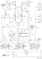
- the hydraulic arrangement shown in Fig. 1 exemplifies a typical integral load clamping circuit 9 for controlling a pair of clamp arms 10, 12 each laterally movable selectively toward or away from each other for selectively clamping or unclamping a load (not shown) between them.
- the clamp arms are laterally closable toward each other to clamp a load by the introduction of pressurized hydraulic fluid through lines 14, 16 and 18 from a manually or electrically controlled clamp valve 20 which, upon movement toward the right in Fig. 1 , introduces hydraulic fluid under pressure from pump 22 through clamping lines 14, 16 and 18 to move pistons 26 and 28 toward each other to clamp a load.
- hydraulic fluid is exhausted from the opposite sides of the pistons 26 and 28 through lines 36 and 38 respectively, through pilot operated check valves 37 and 39 respectively, and through a conventional flow divider/combiner valve 34 to line 32, from which the fluid is exhausted through valve passageway 25 of clamp valve 20 and exhaust line 27 to a hydraulic fluid reservoir 29.
- pressurized hydraulic fluid is introduced from pump 22 through valve passageway 30 and line 32, flow divider/combiner valve 34, and lines 36 and 38 to move the pistons 26 and 28, and their corresponding clamp arms 10 and 12, away from each other thereby opening the clamp arms 10 and 12.
- hydraulic fluid is exhausted from the pistons 26 and 28 and through lines 16 and 18, through a pilot-operated check valve 40 opened by pressure in line 32, and through line 14 and valve passageway 42 to exhaust line 27 and hydraulic reservoir 29.
- the clamp arms 10, 12 are laterally movable bidirectionally in unison selectively either to the left or right in Fig. 1 while the load-clamping valve 20 is closed, so as to perform a side-shifting function, either while clamping a load or without any load.
- hydraulic fluid under pressure is introduced from pump 22 and line 27 through the side-shift valve passageway 46, side-shifting line 48 and thus to line 36, thereby imposing leftward pressure on the piston 26 .
- the leftward pressure on piston 26 causes clamping fluid in line 16 to be transferred to line 18 of the other clamping cylinder, thereby causing corresponding leftward pressure also on piston 28 and the exhaustion of fluid from line 38 through line 50 and valve passageway 52 to the hydraulic reservoir 29, so that the pistons 26 and 28 side-shift to the left in unison.
- No leakage of the fluid is permitted through clamping line 14 during the foregoing left side-shifting process because the pilot-operated check valve 40 preserves the clamping pressure.
- pressurized hydraulic fluid is similarly introduced from pump 22 and line 27 through valve passageway 54 of valve 44 , right side-shifting line 50 and line 38, thereby imposing rightward pressure on the piston 28.
- the rightward pressure on piston 28 can nevertheless cause clamping fluid in line 18 to be transferred to the corresponding opposite line 16 of the other clamping cylinder, thereby causing corresponding rightward pressure on piston 26 and the exhaustion of fluid from line 36 through line 48 and valve passageway 55 to the hydraulic reservoir 29, so that the pistons 26 and 28 side-shift in unison to the right.
- No leakage of the fluid is permitted through clamping line 14 during right side-shifting because pilot-operated check valve 40 preserves the clamping pressure as mentioned above.
- a load hoist valve 56 if moved to the left, selectively conducts hydraulic load-lifting pressurized fluid from line 27 through valve passageway 58 and line 59 to one or more load-hoisting hydraulic cylinders such as 60, 62 which lift the load clamp 10, 12. Movement of the valve 56 to the right exhausts fluid from line 59 through valve passageway 64 to the hydraulic reservoir 29, thereby lowering the clamp 10, 12.
- the load-hoisting cylinders can have any suitable arrangement, including "free lift" cylinder arrangements having different piston diameters for extending sequentially.
- variable weights of the loads may be sensed preferably, but not necessarily, from variable hydraulic pressure in hoist line 59 through a sensing line 66 of a side-shifting force control circuit 68.
- valve 70 In response to such decrease in the side-shift relief pressure setting of relief valve 70, valve 70 opens and thereby relieves the side-shifting pressure in line 71, representing the highest pressure in lines 48 or 50 as sensed between check valves 49 and 51, through line 76 and whichever check-valve 78 or 80 and line 48 or 50 is not exposed to side shifting pressure from valve 44 and therefore can exhaust fluid through valve 44 to reservoir 29.
- the side-shifting pressure in either of lines 48 or 50 is variably limited by the automatically variable relief setting of the valve 70 in response to the variable weight of the load, as sensed through lines 66 and 72.
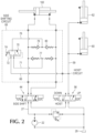
- Fig. 2 shows an exemplary alternative side-shifting circuit with a reversible side-shifting linear actuator 100, which need not be integral with the exemplary clamp circuit 9 (not shown).
- the side-shifting circuit can, if desired, be part of a separate attachment to the lift truck or other load-carrying vehicle, usable in conjunction with a side-shifting unit or as part of a side-shifting unit, possibly together with other attachments which utilize side-shifting such as bale clamps, fork clamps, paper roll clamps, and so forth.
- Fig. 3 shows a further exemplary alternative side-shifting circuit with a reversible rotary hydraulic motor 102 capable of performing a side-shifting function, and which need not be integral with the clamp circuit 9.
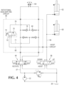
- Fig. 4 shows a further exemplary alternative side-shifting circuit with a rotationally reciprocating hydraulic motor 104 capable of performing a curved side-to-side swinging motion for layer-picking load clamps, and which need not be integral with the clamp circuit 9.
- a layer picking application could be a telescopic boom clamping force control.
Landscapes
- Engineering & Computer Science (AREA)
- Transportation (AREA)
- Structural Engineering (AREA)
- Mechanical Engineering (AREA)
- Civil Engineering (AREA)
- Life Sciences & Earth Sciences (AREA)
- Geology (AREA)
- Fluid Mechanics (AREA)
- Physics & Mathematics (AREA)
- General Engineering & Computer Science (AREA)
- Chemical & Material Sciences (AREA)
- Combustion & Propulsion (AREA)
- Forklifts And Lifting Vehicles (AREA)
- Fluid-Pressure Circuits (AREA)
- Press Drives And Press Lines (AREA)
- Control Of Presses (AREA)
Applications Claiming Priority (2)
| Application Number | Priority Date | Filing Date | Title |
|---|---|---|---|
| US15/267,694 US10494241B2 (en) | 2016-09-16 | 2016-09-16 | Hydraulic clamping systems having load side-shifting variably responsive to load weight |
| PCT/US2016/069365 WO2018052468A1 (en) | 2016-09-16 | 2016-12-30 | Hydraulic clamping systems having load side-shifting variably responsive to load weight |
Publications (3)
| Publication Number | Publication Date |
|---|---|
| EP3512670A1 EP3512670A1 (en) | 2019-07-24 |
| EP3512670A4 EP3512670A4 (en) | 2020-05-13 |
| EP3512670B1 true EP3512670B1 (en) | 2025-06-11 |
Family
ID=61617826
Family Applications (1)
| Application Number | Title | Priority Date | Filing Date |
|---|---|---|---|
| EP16916390.4A Active EP3512670B1 (en) | 2016-09-16 | 2016-12-30 | Hydraulic clamping systems having load side-shifting variably responsive to load weight |
Country Status (10)
| Country | Link |
|---|---|
| US (1) | US10494241B2 (enExample) |
| EP (1) | EP3512670B1 (enExample) |
| JP (1) | JP6810244B2 (enExample) |
| CN (1) | CN109562520B (enExample) |
| AU (1) | AU2016423192B2 (enExample) |
| BR (1) | BR112019001939B1 (enExample) |
| CA (1) | CA3028648C (enExample) |
| ES (1) | ES3036014T3 (enExample) |
| FI (1) | FI3512670T3 (enExample) |
| WO (1) | WO2018052468A1 (enExample) |
Families Citing this family (9)
| Publication number | Priority date | Publication date | Assignee | Title |
|---|---|---|---|---|
| KR102044059B1 (ko) * | 2016-08-02 | 2019-11-12 | 주식회사 두산 | 포크 이동의 제어 장치 |
| CA3007257A1 (en) * | 2017-06-08 | 2018-12-08 | Jody Addicott | Fork-carriage apparatus for a lift truck and valve assembly therefor |
| DE102017115537A1 (de) * | 2017-07-11 | 2019-01-17 | Liebherr-Hydraulikbagger Gmbh | Baumaschine |
| DE102019201599A1 (de) * | 2019-02-07 | 2020-08-13 | Bhs Intralogistics Gmbh | Überführungsanordnung |
| US11655130B2 (en) | 2019-05-22 | 2023-05-23 | Cascade Corporation | Synchronized hybrid clamp force controller for lift truck attachment |
| JP7603087B2 (ja) * | 2020-06-18 | 2024-12-19 | カスケード コーポレイション | リフトトラックアタッチメント用の同期されたハイブリッドクランプ力コントローラ |
| US11142087B1 (en) | 2021-05-10 | 2021-10-12 | Mark Ellery Ogram | Electric vehicle recharging |
| US12304790B1 (en) | 2021-07-20 | 2025-05-20 | Shaw Industries Group, Inc. | Clamp adapter for lift vehicle to facilitate lifting of malleable objects |
| IT202300004011A1 (it) * | 2023-03-06 | 2024-09-06 | Bolzoni Spa | Valvola rigenerativa perfezionata per il controllo dei movimenti di apertura e chiusura delle ganasce di una pinza, in particolare una pinza per carrelli elevatori, e pinza per carrelli elevatori comprendente tale valvola rigenerativa. |
Family Cites Families (34)
| Publication number | Priority date | Publication date | Assignee | Title |
|---|---|---|---|---|
| US2663443A (en) | 1951-04-18 | 1953-12-22 | Baker Raulang Co | Carrier for industrial elevating trucks |
| US2795346A (en) * | 1953-07-16 | 1957-06-11 | Hyster Co | Load grip side shift for lift trucks |
| US3692198A (en) * | 1970-12-28 | 1972-09-19 | Clark Equipment Co | Hydraulic lift truck with small number of fluid lines |
| AT311769B (de) | 1972-04-06 | 1973-12-10 | Voest Ag | Hydraulische Schmiedechargierzange |
| US3971584A (en) * | 1975-03-17 | 1976-07-27 | Gte Sylvania Incorporated | Automatic load compensating clamp truck jaws |
| US3990594A (en) * | 1975-08-29 | 1976-11-09 | Cascade Corporation | Fluid-actuated clamping apparatus and circuit |
| CA1106733A (en) | 1977-07-13 | 1981-08-11 | Clark Equipment Company | Pressure control mechanism for a grapple skidder |
| US4335992A (en) * | 1980-01-07 | 1982-06-22 | Towmotor Corporation | Side shift fork adjustable carriage |
| US4682931A (en) * | 1986-09-22 | 1987-07-28 | Cascade Corporation | Lift truck clamp for handling stacked loads of different sizes |
| JPH075272B2 (ja) * | 1987-07-27 | 1995-01-25 | 株式会社豊田自動織機製作所 | サイドシフトクランプ装置 |
| US5984617A (en) * | 1998-05-11 | 1999-11-16 | Cascade Corporation | Clamp for handling stacked loads of different sizes at different maximum clamping forces |
| US6843636B2 (en) * | 1998-10-07 | 2005-01-18 | Cascade Corporation | Adaptive load-clamping system |
| US6431816B1 (en) * | 1998-10-07 | 2002-08-13 | Cascade Corporation | Adaptive load-clamping system |
| CA2282198C (en) | 1998-10-07 | 2003-06-10 | Cascade Corporation | Adaptive load-clamping system |
| US7056078B2 (en) * | 2003-09-24 | 2006-06-06 | Cascade Corporation | Hydraulically-synchronized clamp for handling stacked loads different sizes |
| US7412919B2 (en) * | 2004-08-04 | 2008-08-19 | Loron, Inc. | Hydraulic force control system for clamping assembly |
| ITMI20051256A1 (it) * | 2005-07-04 | 2007-01-05 | Auramo Oy | Gruppo idraulico di controllo dei bracci di una pinza e pinza comprendente tale gruppo idraulico |
| CN100577554C (zh) * | 2006-04-19 | 2010-01-06 | 浙江佳力科技股份有限公司 | 全液压电动叉车液压系统 |
| CA2553994A1 (fr) * | 2006-07-25 | 2008-01-25 | Michel Lessard | Calculateur de pression hydraulique entierement mecanique |
| US20080063503A1 (en) * | 2006-09-11 | 2008-03-13 | Joseph Lee Garrett | Bale lifting device for the handling of bales of fibrous material |
| US8091467B2 (en) * | 2008-04-30 | 2012-01-10 | Cascade Corporation | Hydraulic valve circuit with damage-control override |
| US9964428B2 (en) * | 2008-10-09 | 2018-05-08 | Cascade Corporation | Equalized hydraulic clamp force control |
| US20100300812A1 (en) * | 2009-05-28 | 2010-12-02 | Georgia-Pacifica Consumer Products LP | Forklift Clamp |
| DE102010038663A1 (de) * | 2010-07-29 | 2012-02-02 | Griptech Gmbh | Vorrichtung zur Aufnahme von Lasten |
| CN201841947U (zh) * | 2010-10-31 | 2011-05-25 | 合肥搬易通科技发展有限公司 | 随车叉车液压系统 |
| US20160243709A1 (en) * | 2010-12-13 | 2016-08-25 | Brian L. Ganz | Robotic gripper |
| US8573070B2 (en) * | 2011-02-22 | 2013-11-05 | The Boeing Company | Force and normality sensing for end effector clamp |
| CN102635581B (zh) * | 2012-05-03 | 2014-07-16 | 泸州长江石油工程机械有限公司 | 用于超深径向井作业的液压控制系统 |
| US8755929B2 (en) * | 2012-10-29 | 2014-06-17 | Cascade Corporation | Interactive clamp force control system for load handling clamps |
| WO2014171953A1 (en) * | 2013-04-19 | 2014-10-23 | Cascade Corporation | Clamping attachment with regenerative hydraulic circuit |
| US9579801B2 (en) * | 2013-06-11 | 2017-02-28 | Somatis Sensor Solutions LLC | Systems and methods for sensing objects |
| CN203451178U (zh) * | 2013-08-16 | 2014-02-26 | 安庆联动属具股份有限公司 | 一种叉车用吊笼式砖块夹 |
| US9309099B2 (en) * | 2014-06-20 | 2016-04-12 | Cascade Corporation | Side-shift limiter |
| US10011468B2 (en) * | 2014-10-30 | 2018-07-03 | Cascade Corporation | Pivoting load-bearing assembly with force sensor |
-
2016
- 2016-09-16 US US15/267,694 patent/US10494241B2/en active Active
- 2016-12-30 AU AU2016423192A patent/AU2016423192B2/en active Active
- 2016-12-30 ES ES16916390T patent/ES3036014T3/es active Active
- 2016-12-30 EP EP16916390.4A patent/EP3512670B1/en active Active
- 2016-12-30 FI FIEP16916390.4T patent/FI3512670T3/fi active
- 2016-12-30 CN CN201680088077.6A patent/CN109562520B/zh active Active
- 2016-12-30 CA CA3028648A patent/CA3028648C/en active Active
- 2016-12-30 JP JP2019505217A patent/JP6810244B2/ja active Active
- 2016-12-30 BR BR112019001939-1A patent/BR112019001939B1/pt active IP Right Grant
- 2016-12-30 WO PCT/US2016/069365 patent/WO2018052468A1/en not_active Ceased
Also Published As
| Publication number | Publication date |
|---|---|
| EP3512670A4 (en) | 2020-05-13 |
| WO2018052468A1 (en) | 2018-03-22 |
| ES3036014T3 (en) | 2025-09-11 |
| JP6810244B2 (ja) | 2021-01-06 |
| FI3512670T3 (fi) | 2025-09-11 |
| US20180079634A1 (en) | 2018-03-22 |
| CN109562520B (zh) | 2021-10-29 |
| CA3028648C (en) | 2021-07-06 |
| JP2019534831A (ja) | 2019-12-05 |
| BR112019001939B1 (pt) | 2022-02-01 |
| EP3512670A1 (en) | 2019-07-24 |
| US10494241B2 (en) | 2019-12-03 |
| CN109562520A (zh) | 2019-04-02 |
| AU2016423192A1 (en) | 2019-01-17 |
| CA3028648A1 (en) | 2018-03-22 |
| AU2016423192B2 (en) | 2022-09-08 |
| BR112019001939A2 (pt) | 2019-05-07 |
Similar Documents
| Publication | Publication Date | Title |
|---|---|---|
| EP3512670B1 (en) | Hydraulic clamping systems having load side-shifting variably responsive to load weight | |
| US10900825B2 (en) | Equalized hydraulic clamp force control | |
| EP2839171B1 (en) | Fluid power control system for mobile load handling equipment | |
| US8979154B2 (en) | Clamping attachment with regenerative hydraulic circuit | |
| EP0959039B1 (en) | Clamp for handling stacked loads of different sizes at different maximum clamping forces | |
| EP0261873B1 (en) | Lift truck load clamp for handling stacked loads of different sizes | |
| US7222484B1 (en) | Hydraulic system with multiple pressure relief levels | |
| CN108025440B (zh) | 具有带有多个可伸缩延伸级段的负载夹持液压缸的夹具 | |
| EP1868935B1 (en) | Hydraulic system for an industrial vehicle | |
| EP1663842B1 (en) | Hydraulically-synchronized clamp for handling stacked loads of different sizes | |
| AU2025205564A1 (en) | Synchronized hybrid clamp force controller for lift truck attachment | |
| JPH075272B2 (ja) | サイドシフトクランプ装置 | |
| JP3885368B2 (ja) | フォークリフトの油圧調整装置 |
Legal Events
| Date | Code | Title | Description |
|---|---|---|---|
| STAA | Information on the status of an ep patent application or granted ep patent |
Free format text: STATUS: THE INTERNATIONAL PUBLICATION HAS BEEN MADE |
|
| PUAI | Public reference made under article 153(3) epc to a published international application that has entered the european phase |
Free format text: ORIGINAL CODE: 0009012 |
|
| STAA | Information on the status of an ep patent application or granted ep patent |
Free format text: STATUS: REQUEST FOR EXAMINATION WAS MADE |
|
| 17P | Request for examination filed |
Effective date: 20190104 |
|
| AK | Designated contracting states |
Kind code of ref document: A1 Designated state(s): AL AT BE BG CH CY CZ DE DK EE ES FI FR GB GR HR HU IE IS IT LI LT LU LV MC MK MT NL NO PL PT RO RS SE SI SK SM TR |
|
| AX | Request for extension of the european patent |
Extension state: BA ME |
|
| DAV | Request for validation of the european patent (deleted) | ||
| DAX | Request for extension of the european patent (deleted) | ||
| REG | Reference to a national code |
Ref country code: DE Ref legal event code: R079 Free format text: PREVIOUS MAIN CLASS: B25J0013080000 Ipc: B66F0009180000 |
|
| A4 | Supplementary search report drawn up and despatched |
Effective date: 20200417 |
|
| RIC1 | Information provided on ipc code assigned before grant |
Ipc: B66F 9/20 20060101ALI20200409BHEP Ipc: B66F 9/14 20060101ALI20200409BHEP Ipc: B66F 9/22 20060101ALI20200409BHEP Ipc: F15B 11/16 20060101ALI20200409BHEP Ipc: B66F 9/18 20060101AFI20200409BHEP |
|
| STAA | Information on the status of an ep patent application or granted ep patent |
Free format text: STATUS: EXAMINATION IS IN PROGRESS |
|
| 17Q | First examination report despatched |
Effective date: 20230504 |
|
| GRAP | Despatch of communication of intention to grant a patent |
Free format text: ORIGINAL CODE: EPIDOSNIGR1 |
|
| STAA | Information on the status of an ep patent application or granted ep patent |
Free format text: STATUS: GRANT OF PATENT IS INTENDED |
|
| INTG | Intention to grant announced |
Effective date: 20250205 |
|
| GRAS | Grant fee paid |
Free format text: ORIGINAL CODE: EPIDOSNIGR3 |
|
| GRAA | (expected) grant |
Free format text: ORIGINAL CODE: 0009210 |
|
| STAA | Information on the status of an ep patent application or granted ep patent |
Free format text: STATUS: THE PATENT HAS BEEN GRANTED |
|
| P01 | Opt-out of the competence of the unified patent court (upc) registered |
Free format text: CASE NUMBER: APP_18479/2025 Effective date: 20250416 |
|
| AK | Designated contracting states |
Kind code of ref document: B1 Designated state(s): AL AT BE BG CH CY CZ DE DK EE ES FI FR GB GR HR HU IE IS IT LI LT LU LV MC MK MT NL NO PL PT RO RS SE SI SK SM TR |
|
| REG | Reference to a national code |
Ref country code: GB Ref legal event code: FG4D |
|
| REG | Reference to a national code |
Ref country code: CH Ref legal event code: EP |
|
| REG | Reference to a national code |
Ref country code: IE Ref legal event code: FG4D |
|
| REG | Reference to a national code |
Ref country code: DE Ref legal event code: R096 Ref document number: 602016092557 Country of ref document: DE |
|
| REG | Reference to a national code |
Ref country code: ES Ref legal event code: FG2A Ref document number: 3036014 Country of ref document: ES Kind code of ref document: T3 Effective date: 20250911 Ref country code: FI Ref legal event code: FGE |
|
| REG | Reference to a national code |
Ref country code: LT Ref legal event code: MG9D |
|
| PG25 | Lapsed in a contracting state [announced via postgrant information from national office to epo] |
Ref country code: NO Free format text: LAPSE BECAUSE OF FAILURE TO SUBMIT A TRANSLATION OF THE DESCRIPTION OR TO PAY THE FEE WITHIN THE PRESCRIBED TIME-LIMIT Effective date: 20250911 Ref country code: GR Free format text: LAPSE BECAUSE OF FAILURE TO SUBMIT A TRANSLATION OF THE DESCRIPTION OR TO PAY THE FEE WITHIN THE PRESCRIBED TIME-LIMIT Effective date: 20250912 |
|
| REG | Reference to a national code |
Ref country code: NL Ref legal event code: MP Effective date: 20250611 |
|
| PG25 | Lapsed in a contracting state [announced via postgrant information from national office to epo] |
Ref country code: BG Free format text: LAPSE BECAUSE OF FAILURE TO SUBMIT A TRANSLATION OF THE DESCRIPTION OR TO PAY THE FEE WITHIN THE PRESCRIBED TIME-LIMIT Effective date: 20250611 |
|
| PG25 | Lapsed in a contracting state [announced via postgrant information from national office to epo] |
Ref country code: HR Free format text: LAPSE BECAUSE OF FAILURE TO SUBMIT A TRANSLATION OF THE DESCRIPTION OR TO PAY THE FEE WITHIN THE PRESCRIBED TIME-LIMIT Effective date: 20250611 |
|
| PG25 | Lapsed in a contracting state [announced via postgrant information from national office to epo] |
Ref country code: RS Free format text: LAPSE BECAUSE OF FAILURE TO SUBMIT A TRANSLATION OF THE DESCRIPTION OR TO PAY THE FEE WITHIN THE PRESCRIBED TIME-LIMIT Effective date: 20250911 |
|
| PG25 | Lapsed in a contracting state [announced via postgrant information from national office to epo] |
Ref country code: LV Free format text: LAPSE BECAUSE OF FAILURE TO SUBMIT A TRANSLATION OF THE DESCRIPTION OR TO PAY THE FEE WITHIN THE PRESCRIBED TIME-LIMIT Effective date: 20250611 |
|
| PG25 | Lapsed in a contracting state [announced via postgrant information from national office to epo] |
Ref country code: NL Free format text: LAPSE BECAUSE OF FAILURE TO SUBMIT A TRANSLATION OF THE DESCRIPTION OR TO PAY THE FEE WITHIN THE PRESCRIBED TIME-LIMIT Effective date: 20250611 |
|
| PG25 | Lapsed in a contracting state [announced via postgrant information from national office to epo] |
Ref country code: PT Free format text: LAPSE BECAUSE OF FAILURE TO SUBMIT A TRANSLATION OF THE DESCRIPTION OR TO PAY THE FEE WITHIN THE PRESCRIBED TIME-LIMIT Effective date: 20251013 |
|
| REG | Reference to a national code |
Ref country code: AT Ref legal event code: MK05 Ref document number: 1802215 Country of ref document: AT Kind code of ref document: T Effective date: 20250611 |