EP0959039B1 - Clamp for handling stacked loads of different sizes at different maximum clamping forces - Google Patents
Clamp for handling stacked loads of different sizes at different maximum clamping forces Download PDFInfo
- Publication number
- EP0959039B1 EP0959039B1 EP99302681A EP99302681A EP0959039B1 EP 0959039 B1 EP0959039 B1 EP 0959039B1 EP 99302681 A EP99302681 A EP 99302681A EP 99302681 A EP99302681 A EP 99302681A EP 0959039 B1 EP0959039 B1 EP 0959039B1
- Authority
- EP
- European Patent Office
- Prior art keywords
- assembly
- clamp arms
- clamping
- actuators
- regulator
- Prior art date
- Legal status (The legal status is an assumption and is not a legal conclusion. Google has not performed a legal analysis and makes no representation as to the accuracy of the status listed.)
- Expired - Lifetime
Links
Images


Classifications
-
- B—PERFORMING OPERATIONS; TRANSPORTING
- B66—HOISTING; LIFTING; HAULING
- B66F—HOISTING, LIFTING, HAULING OR PUSHING, NOT OTHERWISE PROVIDED FOR, e.g. DEVICES WHICH APPLY A LIFTING OR PUSHING FORCE DIRECTLY TO THE SURFACE OF A LOAD
- B66F9/00—Devices for lifting or lowering bulky or heavy goods for loading or unloading purposes
- B66F9/06—Devices for lifting or lowering bulky or heavy goods for loading or unloading purposes movable, with their loads, on wheels or the like, e.g. fork-lift trucks
- B66F9/075—Constructional features or details
- B66F9/12—Platforms; Forks; Other load supporting or gripping members
- B66F9/18—Load gripping or retaining means
- B66F9/184—Roll clamps
-
- B—PERFORMING OPERATIONS; TRANSPORTING
- B66—HOISTING; LIFTING; HAULING
- B66F—HOISTING, LIFTING, HAULING OR PUSHING, NOT OTHERWISE PROVIDED FOR, e.g. DEVICES WHICH APPLY A LIFTING OR PUSHING FORCE DIRECTLY TO THE SURFACE OF A LOAD
- B66F9/00—Devices for lifting or lowering bulky or heavy goods for loading or unloading purposes
- B66F9/06—Devices for lifting or lowering bulky or heavy goods for loading or unloading purposes movable, with their loads, on wheels or the like, e.g. fork-lift trucks
- B66F9/075—Constructional features or details
- B66F9/20—Means for actuating or controlling masts, platforms, or forks
- B66F9/22—Hydraulic devices or systems
Definitions
- the present invention is directed to a lift truck-mounted load-handling clamp adapted for handling stacked loads of different sizes simultaneously, such as two stacked paper rolls of abbreviated length and different diameters. More particularly, the invention is directed to an improvement in the clamp disclosed in U.S. Patent No. 4, 682, 931, which is hereby incorporated by reference, in order to facilitate the selection by the operator of different maximum magnitudes of clamping force to prevent damage to the loads from overclamping.
- a common requirement in the paper industry is the handling of half-length paper rolls, which are normally handled by a lift truck roll clamp in pairs having different diameters, stacked one atop the other.
- Lift truck paper roll clamps specially adapted for handling such stacked rolls have been available in the past and normally consist of a pair of separately-actuated clamp arms on one side of the clamp, in opposed relation to a single, larger clamp arm assembly on the opposite side of the clamp.
- the separately-actuated arms give the clamp the ability to apply clamping force to two cylindrical objects of different diameters stacked one atop the other. Similar clamping capabilities can be useful with respect to other types of loads, such as stacked pairs of bales or cartons of different sizes.
- the override assembly would operate prematurely to shunt pressurized fluid to the other clamp arm before the operator's selected maximum clamping force could be attained.
- such override assembly would not operate at all if it were adjusted to operate in response to a clamping force higher than the maximum force selected by the operator, since such clamping force would not be attained in view of the operator's selection.
- the present invention overcomes the foregoing drawbacks by compatibly providing a selectively-variable clamping force adjuster assembly, enabling the operator to selectively predetermine different maximum magnitudes of clamping force, with an override assembly which operates to override the regulator to enable nonsimultaneous movement of the clamp arms independently of selective variations of the adjuster assembly by the operator.
- such independence is achieved by overriding the regulator automatically in delayed response to a magnitude of clamping force which is less than the different maximum magnitudes of clamping force predeterminable by the adjuster assembly, the delay in response being sufficient to enable such different maximum magnitudes of clamping force to be attained in accordance with the operator's selection.
- a backhanding force controller in order to enable high backhanding force of the clamp arms a backhanding force controller is capable of predetermining one of more maximum magnitudes of backhanding force independently of the regulator.
- FIG. 1 is a simplified top view of an exemplary split paper roll clamp embodying the present invention, shown in engagement with a pair of stacked rolls of different diameters.
- FIG. 2 is a reduced, simplified sectional view taken along line 2-2 of FIG. 1.
- FIG. 3 is a hydraulic circuit diagram of the preferred embodiment of the present invention.
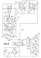
- FIG. 4 is a hydraulic circuit diagram of an alternative embodiment of the present invention.
- An exemplary paper roll clamp designated generally as 10 in FIG. 1, is mounted on a vertically-reciprocating carriage 12 carried by a lift truck mast 14.
- the load clamp comprises a frame 16 mounted on the load carriage 12 connected either fixedly thereto or, as shown in FIG. 1, by a rotator assembly 18.
- Pivotally mounted to the frame 16 at pivot points 20, 22 are a pair of opposing clamping assemblies designated generally as 24 and 26.
- the clamping assembly 24 comprises a pair of vertically-spaced clamp arms 28 and 30, having respective load-engagement pads 28a and 30a, movable separately from each other relative to the frame 16 selectively toward and away from the opposed clamping assembly 26 under the control of fluid power actuators 32 and 34 respectively, each consisting of a double-acting hydraulic cylinder connected between the frame 16 and the respective clamp arms 28 or 30.
- the opposed clamping assembly 26, on the other hand, consists of only a single clamp arm 36 having an elongated load-engagement pad 36a extending vertically so as to oppose the pads of both of the clamp arms 28 and 30.
- the clamp arm 36 pivots with respect to the frame 16 under the control of a further fluid power actuator 38. Alternatively, the arm 36 could be fixed with respect to the frame 16.
- the function of the load clamp 10 is to engage multiple stacked half-length paper rolls, such as 40 and 42, of varying different diameters simultaneously so as to transport them from one location to another. It is also necessary that the clamp be capable of engaging and carrying only a single half-length paper roll, such as roll 40. Carrying of the rolls requires that each be engaged with sufficient clamping force, by the respective pads 28a, 30a and 36a, to be able to support the weight of the loads vertically.
- the clamping force with respect to pads 28a and 30a is supplied by the pressure of hydraulic fluid tending to extend hydraulic cylinders 32 and 34, respectively.
- a hydraulic pump 44 driven by the lift truck engine, delivers fluid under pressure from a hydraulic reservoir 46 to a manually-operable clamp arm directional control valve 48 shown in its centered, or unactuated condition.
- a relief valve 50 sets an upper limit on the pressure of the fluid delivered by pump 44 by opening and bleeding fluid back to the reservoir 46 in response to excessive fluid pressure as determined by the variable setting of the relief valve 50.
- Closing the clamp arms 28 and 30 is accomplished by the lift truck operator's manipulation of valve 48 so as to move its spool to the right in FIG. 3. This delivers pressurized fluid through the input conduit 52 in parallel to lines 56 and 55 to extend hydraulic cylinders 32 and 34 respectively. Simultaneously fluid is exhausted from the opposite sides of cylinders 32 and 34 through respective exhaust lines 60 and 58.
- a selectively-variable clamping force adjuster assembly is preferably a multipressure relief valve assembly consisting of a manually-operable selector valve 61a and pressure-relief valves 61b, 61c and 61d.
- Each of the relief valves 61b, 61c and 61d is set at a different relief pressure, all lower than the relief pressure of valve 50.
- Each valve 61b, 61c and 61d thus sets a different maximum limit on the pressure of the fluid delivered through line 52 to apply clamping force through the hydraulic cylinders 32 and 34, and thereby predetermines a different maximum clamping force.
- the operator alternately selects any of the different maximum pressure limits, and thus any of the different maximum clamping forces, suitable for handling any particular load simply by adjusting the selector valve 61a to select one of the relief valves 61b, 61c or 61d.
- an easily-controllable variable pressure-relief valve or pressure-reducing valve could be associated with the conduit 52 for the same purpose.
- valve 54 combines the flows into a flow which emerges from conduit 57 and is exhausted through valve 48 to the reservoir 46.
- the valve 54 ensures that the hydraulic cylinders 32 and 34 extend simultaneously, and thus that the clamp arms 28 and 30 advance simultaneously toward the opposed clamp arm assembly 36.
- the valve 54 also causes the respective volumetric flow rates in conduits 58 and 60 to be proportional to each other and, assuming that the cylinders 32 and 34 are of the same diameter, preferably equal to each other.
- clamp arm 28 would normally be the first to encounter resistance from the larger-diameter roll 40.
- This resistance restricts the extension of cylinder 32 and reduces the flow exhausted through conduits 60 and 60a and restrictor 54a of the valve 54.
- the valve 54 begins to close restrictor 54b to accomplish a corresponding reduction in flow therethrough.
- restrictor 54a ceases due to the inability of the cylinder 32 to extend further
- restrictor 54b is substantially closed, thereby likewise preventing further extension of cylinder 34 and further closure of clamp arm 30.
- the clamp arm 30 has not yet engaged the smaller-diameter roll 42.
- the fluid pressure in conduits 52, 55 and 56 builds up to that which corresponds to the predetermined maximum clamping force adjustably set by the adjuster assembly 61. Due to the closure of restrictor 54b the pressure in conduit 58 likewise builds up to a level even somewhat higher than that in conduit 55 due to the pressure amplifying effect of the piston and rod assembly of the hydraulic cylinder 34.
- the pressure in conduit 58 is applied through a shuttle valve 66 to an override assembly indicated generally as 67 consisting of a sequence valve 62, a delay orifice 63, and an override bypass valve 64.
- valve 54 When the pressure in conduit 58 exceeds the setting of the sequence valve 62, the valve opens and, after a delay caused by the orifice 63, moves the valve 64 to its bypass condition to override the flow regulator valve 54. This enables fluid from conduit 58 to flow through valve 64 to conduit 60 and through restrictor 54a of the flow regulator valve 54. In response to such flow, regulator valve 54 opens restrictor 54b to permit an equal flow therethrough, and hydraulic cylinder 34 is therefore permitted to extend even though cylinder 32 cannot extend further due to the resistance of the larger-diameter roll 40.
- the sequence valve 62 of the override assembly 67 must be set to open and thereby override the regulator valve 54 in response to a magnitude of clamping force, represented by the clamping pressure in conduit 52, which is less than the different maximum magnitudes of clamping force predetermined by the maximum pressures selectable by the adjuster assembly 61. Otherwise, sufficient pressure will not be present in conduit 58 to open the sequence valve 62 and operate the override assembly at the lowest clamping pressure selectable by the adjuster assembly 61.
- the setting of sequence valve 62 would be such as to cause the valve 62 to open in response to a clamping pressure of approximately 48,26 bar in conduit 52.
- the delay provided by the delay orifice 63 is necessary to prevent the bypass valve 64 from opening prematurely before higher clamping pressures selected by the adjuster assembly 61 are attained. Otherwise, premature opening of the bypass valve 64 would create a low resistance to extension of the parallel cylinder 34, thus preventing the attainment of the selected maximum clamping pressure and resultant clamping force by cylinder 32.
- delay orifice 63 is a preferred structure for accomplishing the needed delay in overriding the flow regulator 54
- other delay-causing structures such as an accumulator could alternatively be employed.
- other hydraulic flow regulators such as a pair of interconnected rotary flow regulators, could be used in ensure simultaneous proportional flows through conduits 58 and 60.
- Cylinder 34 continues to extend until encountering the resistance of roll 42, at which time clamping force is applied and the pressure in conduit 55 rises to a maximum level equal to that in conduit 56, after which the directional control valve 48 may be deactivated and the rolls lifted. If only a single roll 40 were present, the load clamping operation could be halted by deactivation of control valve 48 as soon as sufficient clamping pressure had been built up in conduit 56 upon initial engagement with the roll 40, and there would be no need to further extend the cylinder 34 to further close clamp arm 30.
- the override assembly 67 has the same effect on either one of the clamp arms 28 and 30 by virtue of its ability to sense pressure in either conduit 58 or 60 through shuttle valve 66. Thus it would make no difference if the clamp 10 had been inverted by rotator 18 such that the clamp arm 30 is in the lower position for engaging roll 40. In such case, the operation of cylinder 34 and clamp arm 30 would be identical to that just described with respect to cylinder 32 and clamp arm 28, and vice versa.
- the clamp arms will open simultaneously maintaining their different positions as long as the operator actuates the control valve 48. If one clamp arm, such as 28, is used in a backhanding mode to push a load, causing substantial resistance to further opening, flow to its cylinder 32 through restrictor 54a will decrease or cease. Accordingly, the valve 54 tends to close the opposite restrictor 54b, restricting or blocking the flow to cylinder 34 because of the requirement by valve 54 for simultaneous flows to the two cylinders.
- the regulator valve 54 cannot be overridden by the operator's continued actuation of control valve 48 because opening of the sequence valve 62 is opposed, through drain line 62a, by the same pressure tending to open it. Moreover, the regulator valve 54 has no pressure limit above which the restrictors 54a and 54b can be forced to open. These factors enable a backhanding force controller consisting of variable relief valves 76 and 78 in parallel with the valve 54 to predetermine one or more maximum magnitudes of backhanding force to be imposed by fluid pressure in conduit 57 to open the clamp arms, independently of the regulator valve 54 and independently of the override assembly 67 which is temporarily disabled.
- valve 78 sets the desired maximum backhanding relief pressure for cylinder 34.
- the maximum backhanding relief pressures set by valves 76 and 78 are lower than that of relief valve 50.
- FIG. 4 shows an alternative embodiment of the invention where the fluid regulator 154 and override assembly 167 are interposed in a fluid conduit assembly through which fluid flows to the actuator cylinders 132 and 134, rather than from the cylinder as in FIG. 3, during the load clamping operation.
- those elements corresponding to the elements of FIG. 3 have the same reference numerals as in FIG. 3 increased by 100.
- the flow regulator divider/combiner valve 154 operates in a dividing mode during closure of the clamp arms, receiving pressurized fluid through conduit 152 and dividing it into simultaneous flows through restrictors 154a and 154b to ensure simultaneous extension of the cylinders 132 and 134.
- Predetermined different maximum magnitudes of clamping force are selected by means of the adjuster assembly 161.
- the override bypass valve 164 can open to permit nonsimultaneous arm closure.
- the opening of the bypass valve 164 is delayed sufficiently by the orifice 163 to permit the selected maximum clamping pressure to be achieved and trapped by a respective pilot-operated check valve such as 172 or 174.
- pressurized fluid is fed in parallel to conduits 158 and 160 from valve 148 and conduit 157 to retract cylinders 134 and 132, simultaneous retraction of the cylinders being ensured by the combining function of regulator valve 154 with respect to the fluid exhausted through conduits 156 and 155 from the cylinders 132 and 134.
- backhanding force controller relief valve 176 or 178 offers sufficient resistance to the exhaust of fluid from the second cylinder 134 or 132, respectively, that the required backhanding pressure and force can be attained in the first cylinder.
- the override bypass valve 164 is prevented from opening by opposing pressure in drain line 162a when the clamp arms are opening.
Description
- The present invention is directed to a lift truck-mounted load-handling clamp adapted for handling stacked loads of different sizes simultaneously, such as two stacked paper rolls of abbreviated length and different diameters. More particularly, the invention is directed to an improvement in the clamp disclosed in U.S. Patent No. 4, 682, 931, which is hereby incorporated by reference, in order to facilitate the selection by the operator of different maximum magnitudes of clamping force to prevent damage to the loads from overclamping.
- A common requirement in the paper industry is the handling of half-length paper rolls, which are normally handled by a lift truck roll clamp in pairs having different diameters, stacked one atop the other. Lift truck paper roll clamps specially adapted for handling such stacked rolls have been available in the past and normally consist of a pair of separately-actuated clamp arms on one side of the clamp, in opposed relation to a single, larger clamp arm assembly on the opposite side of the clamp. The separately-actuated arms give the clamp the ability to apply clamping force to two cylindrical objects of different diameters stacked one atop the other. Similar clamping capabilities can be useful with respect to other types of loads, such as stacked pairs of bales or cartons of different sizes.
- The above-mentioned U.S. Patent No. 4,682,931 provides a solution to a problem previously experienced by clamps of this type due to their inability to attain the required clamping force on one of the separately-actuated clamp arms without attaining it also on the other separately-actuated arm. For example, such clamp structures have the separately-actuated clamp arms powered by separate hydraulic cylinders connected in parallel to a source of pressurized fluid, requiring that the pressure buildup in the two cylinders during clamping be identical. The problem with such a structure is that, if only a single half-length roll or other load is to be handled, clamping pressure on the load-engaging arm cannot be attained until the other arm is closed to its maximum extent, which is very time-consuming. Conversely, on opening of the clamp arms to release a load, the release of both clamp arms is not usually simultaneous due to different frictional resistances in the respective arm mechanisms, sometimes requiring full opening of one clamp arm before the other can release sufficiently to disengage the load.
- The above-mentioned U.S. Patent No. 4,682,931 offered a solution to these prior problems by providing a flow regulator of the divider/combiner type which required the respective movements (or lack thereof) of the pair of clamp arms to be simultaneous until the regulator was overridden by an override assembly automatically in response to the attainment of a predetermined clamping force by one of the clamp arms, after which nonsimultaneous movement of the clamp arms was enabled by the override assembly.
- However, a significant drawback to the system of U.S. Patent No. 4,682,931 developed when it became important for clamping systems to have easily-operable selectively-variable clamping force adjustment systems, usually of the multipressure relief type, so that the operator could quickly select a different predetermined maximum magnitude of clamping force for each different load to prevent damage to the load from overclamping. The override assembly of the '931 patent, due to its automatic responsiveness to the attainment of a predetermined clamping force and its inability to change its responsiveness to accommodate higher or lower clamping forces without time-consuming adjustment, could not operate properly independently of the operator's alternating selections of different maximum clamping forces for each different load. For example, if the override assembly were adjusted to operate in response to the attainment by one of the clamp arms of a clamping force lower than the maximum force selected by the operator, the override assembly would operate prematurely to shunt pressurized fluid to the other clamp arm before the operator's selected maximum clamping force could be attained. Alternatively, such override assembly would not operate at all if it were adjusted to operate in response to a clamping force higher than the maximum force selected by the operator, since such clamping force would not be attained in view of the operator's selection.
- Another drawback to the system of U.S. Patent No. 4,682,931 was that, when opening the clamp arms, the maximum opening force attainable by each clamp arm was limited by the pressure limit of the divider/combiner flow regulator valve in its combining mode, unless the other clamp arm had been opened completely. This was because fluid pressure tending to open the clamp arms in parallel was limited to that which opened the clamp arm having the least resistance to opening. If it were desired to push a load with the back of a first clamp arm, referred to as "backhanding" the load, while the second clamp arm encountered no such loading, the only resistance to opening of the second clamp arm, unless it were fully opened, was that imposed by the pressure of the fluid exhausted from the second clamp arm's fluid actuator during opening. Such exhaust pressure was dependent upon the pressure limit of the flow regulator.
- The present invention overcomes the foregoing drawbacks by compatibly providing a selectively-variable clamping force adjuster assembly, enabling the operator to selectively predetermine different maximum magnitudes of clamping force, with an override assembly which operates to override the regulator to enable nonsimultaneous movement of the clamp arms independently of selective variations of the adjuster assembly by the operator.
- According to a separate aspect of the invention, such independence is achieved by overriding the regulator automatically in delayed response to a magnitude of clamping force which is less than the different maximum magnitudes of clamping force predeterminable by the adjuster assembly, the delay in response being sufficient to enable such different maximum magnitudes of clamping force to be attained in accordance with the operator's selection.
- According to another separate aspect of the invention, in order to enable high backhanding force of the clamp arms a backhanding force controller is capable of predetermining one of more maximum magnitudes of backhanding force independently of the regulator.
- The foregoing and other objectives, features, and advantages of the invention will be more readily understood upon consideration of the following detailed description, taken in conjunction with the accompanying drawings.
- FIG. 1 is a simplified top view of an exemplary split paper roll clamp embodying the present invention, shown in engagement with a pair of stacked rolls of different diameters.
- FIG. 2 is a reduced, simplified sectional view taken along line 2-2 of FIG. 1.
- FIG. 3 is a hydraulic circuit diagram of the preferred embodiment of the present invention.
- FIG. 4 is a hydraulic circuit diagram of an alternative embodiment of the present invention.
- An exemplary paper roll clamp, designated generally as 10 in FIG. 1, is mounted on a vertically-reciprocating
carriage 12 carried by alift truck mast 14. The load clamp comprises aframe 16 mounted on theload carriage 12 connected either fixedly thereto or, as shown in FIG. 1, by arotator assembly 18. Pivotally mounted to theframe 16 atpivot points clamping assembly 24 comprises a pair of vertically-spacedclamp arms 28 and 30, having respective load-engagement pads frame 16 selectively toward and away from theopposed clamping assembly 26 under the control offluid power actuators frame 16 and therespective clamp arms 28 or 30. Theopposed clamping assembly 26, on the other hand, consists of only asingle clamp arm 36 having an elongated load-engagement pad 36a extending vertically so as to oppose the pads of both of theclamp arms 28 and 30. Theclamp arm 36 pivots with respect to theframe 16 under the control of a furtherfluid power actuator 38. Alternatively, thearm 36 could be fixed with respect to theframe 16. - The function of the
load clamp 10 is to engage multiple stacked half-length paper rolls, such as 40 and 42, of varying different diameters simultaneously so as to transport them from one location to another. It is also necessary that the clamp be capable of engaging and carrying only a single half-length paper roll, such asroll 40. Carrying of the rolls requires that each be engaged with sufficient clamping force, by therespective pads pads hydraulic cylinders - The control of
cylinders hydraulic pump 44, driven by the lift truck engine, delivers fluid under pressure from ahydraulic reservoir 46 to a manually-operable clamp armdirectional control valve 48 shown in its centered, or unactuated condition. Arelief valve 50 sets an upper limit on the pressure of the fluid delivered bypump 44 by opening and bleeding fluid back to thereservoir 46 in response to excessive fluid pressure as determined by the variable setting of therelief valve 50. - Closing the
clamp arms 28 and 30 is accomplished by the lift truck operator's manipulation ofvalve 48 so as to move its spool to the right in FIG. 3. This delivers pressurized fluid through theinput conduit 52 in parallel tolines hydraulic cylinders cylinders respective exhaust lines - A selectively-variable clamping force adjuster assembly, indicated generally as 61, is preferably a multipressure relief valve assembly consisting of a manually-
operable selector valve 61a and pressure-relief valves relief valves valve 50. Eachvalve line 52 to apply clamping force through thehydraulic cylinders selector valve 61a to select one of therelief valves conduit 52 for the same purpose. - As pressurized fluid is delivered through the
conduit 52 to thehydraulic cylinders conduits conduits valve 54. Thevalve 54 combines the flows into a flow which emerges fromconduit 57 and is exhausted throughvalve 48 to thereservoir 46. Thevalve 54 ensures that thehydraulic cylinders clamp arms 28 and 30 advance simultaneously toward the opposedclamp arm assembly 36. Thevalve 54 also causes the respective volumetric flow rates inconduits cylinders - Assuming that rolls of different diameters corresponding to
rolls clamp arm 28 would normally be the first to encounter resistance from the larger-diameter roll 40. This resistance restricts the extension ofcylinder 32 and reduces the flow exhausted throughconduits restrictor 54a of thevalve 54. In response thereto, thevalve 54 begins to closerestrictor 54b to accomplish a corresponding reduction in flow therethrough. When flow throughrestrictor 54a ceases due to the inability of thecylinder 32 to extend further,restrictor 54b is substantially closed, thereby likewise preventing further extension ofcylinder 34 and further closure of clamp arm 30. At this point the clamp arm 30 has not yet engaged the smaller-diameter roll 42. However, by continued actuation of thedirectional control valve 48 tending to close the clamp arms, the fluid pressure inconduits adjuster assembly 61. Due to the closure ofrestrictor 54b the pressure inconduit 58 likewise builds up to a level even somewhat higher than that inconduit 55 due to the pressure amplifying effect of the piston and rod assembly of thehydraulic cylinder 34. The pressure inconduit 58 is applied through ashuttle valve 66 to an override assembly indicated generally as 67 consisting of asequence valve 62, adelay orifice 63, and anoverride bypass valve 64. When the pressure inconduit 58 exceeds the setting of thesequence valve 62, the valve opens and, after a delay caused by theorifice 63, moves thevalve 64 to its bypass condition to override theflow regulator valve 54. This enables fluid fromconduit 58 to flow throughvalve 64 toconduit 60 and throughrestrictor 54a of theflow regulator valve 54. In response to such flow,regulator valve 54 opens restrictor 54b to permit an equal flow therethrough, andhydraulic cylinder 34 is therefore permitted to extend even thoughcylinder 32 cannot extend further due to the resistance of the larger-diameter roll 40. - The
sequence valve 62 of theoverride assembly 67 must be set to open and thereby override theregulator valve 54 in response to a magnitude of clamping force, represented by the clamping pressure inconduit 52, which is less than the different maximum magnitudes of clamping force predetermined by the maximum pressures selectable by theadjuster assembly 61. Otherwise, sufficient pressure will not be present inconduit 58 to open thesequence valve 62 and operate the override assembly at the lowest clamping pressure selectable by theadjuster assembly 61. By way of example, if the threerelief valves sequence valve 62 would be such as to cause thevalve 62 to open in response to a clamping pressure of approximately 48,26 bar inconduit 52. - In view of the necessarily low setting of the
sequence valve 62, the delay provided by thedelay orifice 63 is necessary to prevent thebypass valve 64 from opening prematurely before higher clamping pressures selected by theadjuster assembly 61 are attained. Otherwise, premature opening of thebypass valve 64 would create a low resistance to extension of theparallel cylinder 34, thus preventing the attainment of the selected maximum clamping pressure and resultant clamping force bycylinder 32. Once the selected predetermined maximum clamping pressure is attained incylinder 32, it is trapped therein by a pilot-operatedcheck valve 72, after which the delayed opening of thebypass valve 64 occurs to permit the further extension ofcylinder 34 without limiting the clamping pressure incylinder 32. - Although the
delay orifice 63 is a preferred structure for accomplishing the needed delay in overriding theflow regulator 54, other delay-causing structures such as an accumulator could alternatively be employed. Also, instead of the flow divider/combiner valve 54, other hydraulic flow regulators, such as a pair of interconnected rotary flow regulators, could be used in ensure simultaneous proportional flows throughconduits -
Cylinder 34 continues to extend until encountering the resistance ofroll 42, at which time clamping force is applied and the pressure inconduit 55 rises to a maximum level equal to that inconduit 56, after which thedirectional control valve 48 may be deactivated and the rolls lifted. If only asingle roll 40 were present, the load clamping operation could be halted by deactivation ofcontrol valve 48 as soon as sufficient clamping pressure had been built up inconduit 56 upon initial engagement with theroll 40, and there would be no need to further extend thecylinder 34 to further close clamp arm 30. - The
override assembly 67 has the same effect on either one of theclamp arms 28 and 30 by virtue of its ability to sense pressure in eitherconduit shuttle valve 66. Thus it would make no difference if theclamp 10 had been inverted byrotator 18 such that the clamp arm 30 is in the lower position for engagingroll 40. In such case, the operation ofcylinder 34 and clamp arm 30 would be identical to that just described with respect tocylinder 32 and clamparm 28, and vice versa. - When the load is to be disengaged, the operator moves the spool of the
control valve 48 to the left in FIG. 3, such that pressurized fluid frompump 44 is directed throughconduit 57 to the rod end of eachhydraulic cylinder check valves conduits conduits Regulator valve 54, acting now as a divider valve, requires simultaneous flows throughconduits regulator valve 54, acting in its dividing mode, causes substantially simultaneous release of the twoclamp arms 28 and 30. - If, upon the initiation of opening, the clamp arms are in different positions as shown, for example, in FIGS. 1 and 2, the clamp arms will open simultaneously maintaining their different positions as long as the operator actuates the
control valve 48. If one clamp arm, such as 28, is used in a backhanding mode to push a load, causing substantial resistance to further opening, flow to itscylinder 32 throughrestrictor 54a will decrease or cease. Accordingly, thevalve 54 tends to close theopposite restrictor 54b, restricting or blocking the flow tocylinder 34 because of the requirement byvalve 54 for simultaneous flows to the two cylinders. However, unlike the load clamping operation described previously, theregulator valve 54 cannot be overridden by the operator's continued actuation ofcontrol valve 48 because opening of thesequence valve 62 is opposed, throughdrain line 62a, by the same pressure tending to open it. Moreover, theregulator valve 54 has no pressure limit above which therestrictors variable relief valves valve 54 to predetermine one or more maximum magnitudes of backhanding force to be imposed by fluid pressure inconduit 57 to open the clamp arms, independently of theregulator valve 54 and independently of theoverride assembly 67 which is temporarily disabled. For example, if a substantial backhanding force exerted bycylinder 32 is desired whilecylinder 34 is experiencing no significant resistance to opening, the relief pressure to whichforce controller valve 76 is set will ensure the required backhanding pressure inconduit 60 by preventing the loss of pressure through theparallel conduit 58 tocylinder 34. Alternatively,valve 78 sets the desired maximum backhanding relief pressure forcylinder 34. The maximum backhanding relief pressures set byvalves relief valve 50. - FIG. 4 shows an alternative embodiment of the invention where the
fluid regulator 154 andoverride assembly 167 are interposed in a fluid conduit assembly through which fluid flows to theactuator cylinders combiner valve 154 operates in a dividing mode during closure of the clamp arms, receiving pressurized fluid throughconduit 152 and dividing it into simultaneous flows throughrestrictors cylinders adjuster assembly 161. In delayed response to a magnitude of fluid pressure determined by the setting of thesequence valve 162, theoverride bypass valve 164 can open to permit nonsimultaneous arm closure. As before, even though the setting ofvalve 162 is less than the different maximum magnitudes of pressure selected by theadjuster assembly 161, the opening of thebypass valve 164 is delayed sufficiently by theorifice 163 to permit the selected maximum clamping pressure to be achieved and trapped by a respective pilot-operated check valve such as 172 or 174. - To open the clamp arms, pressurized fluid is fed in parallel to
conduits valve 148 andconduit 157 to retractcylinders regulator valve 154 with respect to the fluid exhausted throughconduits cylinders controller relief valve second cylinder override bypass valve 164 is prevented from opening by opposing pressure indrain line 162a when the clamp arms are opening. - The terms and expressions which have been employed in the foregoing specification are used therein as terms of description and not of limitation, and there is no intention, in the use of such terms and expressions, of excluding equivalents of the features shown and described or portions thereof, it being recognized that the scope of the invention is defined and limited only by the claims which follow.
Claims (9)
- A load-handling clamp (10) having a frame (16) adapted to be mounted upon the lifting apparatus (12) of a lift truck so as to be selectively movable vertically by said lifting apparatus, first and second selectively openable and closable opposing clamping assemblies (24, 26) mounted upon said frame , the first clamping assembly (24) comprising at least two clamp arms (28, 30) movable separately from each other relative to said frame selectively toward and away from the second clamping assembly (26), a pair of power actuators (32, 34, 132, 134), each associated with a respective clamp arm, for moving said clamp arms separately from each other selectively toward and away from the second clamping assembly and imposing clamping force through said clamp arms in a direction toward said second clamping assembly, a regulator (54, 154) connected to said pair of actuators for causing the respective movements of said two clamp arms in said direction to be simultaneous with each other, and an override assembly (67, 167) capable of overriding said regulator so as to permit one of said two clamp arms to move in said direction without simultaneous movement in said direction by the other of said clamp arms, characterized by a selectively-variable clamping force adjuster assembly (61, 161) associated with said actuators and capable of selectively predetermining different maximum magnitudes of said clamping force imposed by said clamp arms, said override assembly overriding said regulator automatically in response to resistance to movement in said direction by said other of said two clamp arms independently of selective variations of said clamping force adjuster assembly which predetermine said different maximum magnitudes of clamping force.
- The apparatus of claim 1 wherein said power actuators comprise a two fluid power actuators (32, 34, 132, 134), and wherein said regulator is a fluid regulator (54, 154) capable of regulating respective flows of fluid through said actuators.
- The apparatus of claim 2 wherein said fluid regulator (54) is interposed in a fluid conduit assembly (58, 60) through which fluid flows from said actuators (32, 34) during movement of said clamp arms (28, 30) in said direction toward said second clamping assembly (26).
- The apparatus of claim 2 wherein said fluid regulator (154) is interposed in a fluid conduit assembly (152, 155, 156) through which fluid flows to said actuators (132, 134) during movement of said clamp arms (28, 30) in said direction toward said second clamping assembly (26).
- The apparatus of claim 1, 2, 3 or 4 which includes a backhanding force controller (76, 78, 176, 178) capable of predetermining one or more maximum magnitudes of force, imposed by at least one of said clamp arms (28, 30) while both of said arms are moving in a direction away from said second clamping assembly (26), independently of said regulator (54, 154).
- The apparatus of any one of the preceding claims wherein said overide assembly (67, 167) is adapted to override said regulator (54, 154) automatically in response to a magnitude of said clamping force which is less than said different maximum magnitudes of clamping force predetermined by said clamping force adjuster assembly (61, 161), said response being delayed sufficiently to enable attainment of any of said different maximum magnitudes of clamping force, as selected by said adjuster assembly, in one of said clamp arms (28, 30) without requiring said attainment in the other of said clamp arms.
- The apparatus of claim 2, 3 or 4, or claim 5 when dependent on claim 2, 3 or 4, wherein said clamping force adjuster assembly (61, 161) is a fluid pressure adjuster assembly associated with said fluid power actuators (32, 34, 132, 134) capable of selectively predetermining different maximum magnitudes of fluid pressure causing said actuators to impose said clamping force, said override assembly (67, 167) overriding said regulator (54, 154) automatically in response to a magnitude of said fluid pressure which is less than said different maximum magnitudes of fluid pressure predetermined by said adjuster assembly, said response being delayed sufficiently to enable attainment of any of said different maximum magnitudes of fluid pressure, as selected by said adjuster assembly, in one of said actuators without requiring said attainment in the other said actuators.
- The apparatus of claims 5 and 7 wherein the backhanding fluid pressure controller (76, 78) is capable of selectively predetermining one or more maximum magnitudes of fluid pressure, causing said actuators to move said clamp arms away from said second clamping assembly, independently of said regulator (54).
- The apparatus of claims 5 and 7 wherein the backhanding fluid pressure controller (176, 178) is capable of predetermining one or more maximum magnitudes of fluid pressure applied to at least one of said actuators, while both of said actuators are moving said clamp arms away from said second clamping assembly, independently of said regulator (54).
Applications Claiming Priority (2)
| Application Number | Priority Date | Filing Date | Title |
|---|---|---|---|
| US09/076,000 US5984617A (en) | 1998-05-11 | 1998-05-11 | Clamp for handling stacked loads of different sizes at different maximum clamping forces |
| US76000 | 1998-05-11 |
Publications (3)
| Publication Number | Publication Date |
|---|---|
| EP0959039A2 EP0959039A2 (en) | 1999-11-24 |
| EP0959039A3 EP0959039A3 (en) | 2002-09-25 |
| EP0959039B1 true EP0959039B1 (en) | 2004-01-21 |
Family
ID=22129292
Family Applications (1)
| Application Number | Title | Priority Date | Filing Date |
|---|---|---|---|
| EP99302681A Expired - Lifetime EP0959039B1 (en) | 1998-05-11 | 1999-04-06 | Clamp for handling stacked loads of different sizes at different maximum clamping forces |
Country Status (6)
| Country | Link |
|---|---|
| US (1) | US5984617A (en) |
| EP (1) | EP0959039B1 (en) |
| JP (1) | JP3947630B2 (en) |
| CA (1) | CA2261493C (en) |
| DE (1) | DE69914252T2 (en) |
| FI (1) | FI117134B (en) |
Families Citing this family (19)
| Publication number | Priority date | Publication date | Assignee | Title |
|---|---|---|---|---|
| AU2001250027A1 (en) * | 2000-03-06 | 2001-09-17 | Jervis B. Webb Company | Apparatus for transport and delivery of articles |
| US6318949B1 (en) | 2000-07-07 | 2001-11-20 | Cascade Corporation | Clamp for handling stacked loads of different sizes |
| ITVR20020065A1 (en) * | 2002-06-12 | 2003-12-12 | Roncari S R L | FORCES CONTROL AND COMMAND DEVICE FOR THE TIGHTENING OF LOADS TO BE TRANSPORTED BY LIFT TRUCKS OR SIMILAR. |
| US7056078B2 (en) * | 2003-09-24 | 2006-06-06 | Cascade Corporation | Hydraulically-synchronized clamp for handling stacked loads different sizes |
| DE102005002715A1 (en) * | 2005-01-20 | 2006-08-03 | Krones Ag | Method and device for holding vessels |
| US7452176B2 (en) * | 2005-04-14 | 2008-11-18 | Cnh America Llc | Material clamping mechanism |
| ITMI20051256A1 (en) * | 2005-07-04 | 2007-01-05 | Auramo Oy | HYDRAULIC GROUP TO CONTROL THE ARMS OF A CALIPER AND THE CALIPER INCLUDING THE HYDRAULIC GROUP |
| EP2036850B1 (en) * | 2007-09-11 | 2012-05-16 | Caterpillar Work Tools B. V. | Work tool for a machine |
| US8091467B2 (en) * | 2008-04-30 | 2012-01-10 | Cascade Corporation | Hydraulic valve circuit with damage-control override |
| US8078315B2 (en) * | 2008-05-08 | 2011-12-13 | Cascade Corporation | Control system for a load handling clamp |
| IT1400813B1 (en) * | 2010-06-15 | 2013-07-02 | A C S S R L | MARTINETTO AND HANDLING DEVICE FOR A CEDEVAL BODY INCLUDING SUCH MARTINETTO |
| US9630821B2 (en) | 2011-09-06 | 2017-04-25 | Loron, Inc. | Clamping assembly for load-carrying vehicle |
| CN103511373B (en) * | 2012-06-26 | 2016-08-03 | 安庆联动属具股份有限公司 | Synchronous control hydraulic system |
| US8755929B2 (en) | 2012-10-29 | 2014-06-17 | Cascade Corporation | Interactive clamp force control system for load handling clamps |
| US9114963B2 (en) * | 2013-02-26 | 2015-08-25 | Cascade Corporation | Clamping surface positioning system for mobile load-handling clamps |
| US10494241B2 (en) * | 2016-09-16 | 2019-12-03 | Cascade Corporation | Hydraulic clamping systems having load side-shifting variably responsive to load weight |
| WO2020132643A1 (en) * | 2018-12-21 | 2020-06-25 | Rightline Equipment, Inc. | Lift truck attachment with smart clamp |
| US11034565B2 (en) | 2019-03-05 | 2021-06-15 | Cascade Corporation | Revolving paper roll clamp with short arm drift prevention |
| US20230136144A1 (en) * | 2020-03-08 | 2023-05-04 | Rightline Equipment, Inc. | Smart Clamp with Base-side Blocking Valve |
Family Cites Families (14)
| Publication number | Priority date | Publication date | Assignee | Title |
|---|---|---|---|---|
| US2706060A (en) * | 1952-02-23 | 1955-04-12 | John J Ferrario | Apparatus for lifting and transporting cylindrical articles |
| US3583586A (en) * | 1969-02-06 | 1971-06-08 | Jerry Fred Burton | Lift truck apparatus for manipulating storage drums |
| US3990594A (en) * | 1975-08-29 | 1976-11-09 | Cascade Corporation | Fluid-actuated clamping apparatus and circuit |
| US4127205A (en) * | 1977-09-19 | 1978-11-28 | Cascade Corporation | Lift truck load clamp for handling paper rolls |
| US4318661A (en) * | 1980-03-24 | 1982-03-09 | Dozier Equipment International Company | Drum handling device for forklift |
| US4397495A (en) * | 1981-06-29 | 1983-08-09 | Clark Equipment Company | Automatic grip control circuit for a grapple mechanism |
| FR2578824B1 (en) * | 1985-03-15 | 1988-04-08 | Mennesson Jean Francois | PROCESS AND DEVICES FOR GRIPPING AND HANDLING BULK PRODUCTS |
| JPS61241039A (en) * | 1985-04-16 | 1986-10-27 | Nippei Toyama Corp | Confirming device for clamp |
| US4682931A (en) * | 1986-09-22 | 1987-07-28 | Cascade Corporation | Lift truck clamp for handling stacked loads of different sizes |
| FI84715C (en) * | 1990-02-23 | 1992-01-10 | Auramo Cargo Systems Oy | Method and apparatus for handling cargo |
| FI85260C (en) * | 1990-07-11 | 1992-03-25 | Vesa Kaehoenen | FOERFARANDE OCH SYSTEM FOER ATT INSTAELLA HYDRAULTRYCKET SOM VERKAR PAO ETT HYDRAULISKT GRIPORGAN. |
| US5308132A (en) * | 1992-10-05 | 1994-05-03 | Motorola, Inc. | Circuit assembly device for programmably controlling placement force and method thereto |
| US5417464A (en) * | 1993-12-10 | 1995-05-23 | Cascade Corporation | Slip-correcting load-clamping system |
| SE9601602L (en) * | 1996-04-26 | 1997-07-14 | Nymek Ab | Control for a load handling device |
-
1998
- 1998-05-11 US US09/076,000 patent/US5984617A/en not_active Expired - Lifetime
-
1999
- 1999-02-12 CA CA002261493A patent/CA2261493C/en not_active Expired - Fee Related
- 1999-03-16 JP JP07020899A patent/JP3947630B2/en not_active Expired - Fee Related
- 1999-03-24 FI FI990656A patent/FI117134B/en active IP Right Grant
- 1999-04-06 EP EP99302681A patent/EP0959039B1/en not_active Expired - Lifetime
- 1999-04-06 DE DE1999614252 patent/DE69914252T2/en not_active Expired - Fee Related
Also Published As
| Publication number | Publication date |
|---|---|
| EP0959039A3 (en) | 2002-09-25 |
| FI990656A (en) | 1999-11-12 |
| DE69914252T2 (en) | 2004-11-18 |
| US5984617A (en) | 1999-11-16 |
| EP0959039A2 (en) | 1999-11-24 |
| FI117134B (en) | 2006-06-30 |
| JPH11322078A (en) | 1999-11-24 |
| FI990656A0 (en) | 1999-03-24 |
| DE69914252D1 (en) | 2004-02-26 |
| JP3947630B2 (en) | 2007-07-25 |
| CA2261493A1 (en) | 1999-11-11 |
| CA2261493C (en) | 2002-04-16 |
Similar Documents
| Publication | Publication Date | Title |
|---|---|---|
| EP0959039B1 (en) | Clamp for handling stacked loads of different sizes at different maximum clamping forces | |
| DE69930074T2 (en) | Adaptive load gripping system | |
| US4682931A (en) | Lift truck clamp for handling stacked loads of different sizes | |
| US6439826B1 (en) | Adaptive load-clamping system | |
| US6843636B2 (en) | Adaptive load-clamping system | |
| US7412919B2 (en) | Hydraulic force control system for clamping assembly | |
| CN109562520B (en) | Load side shifting hydraulic clamping system with variable load weight response | |
| US6318949B1 (en) | Clamp for handling stacked loads of different sizes | |
| JP2019509230A (en) | Clamp having a telescoping load clamping hydraulic cylinder with a plurality of extension stages adapted to apply a load clamping force alternatively in response to a load lifting force or load size | |
| US20090050413A1 (en) | Clamp force control | |
| CA2155450C (en) | A logging grapple | |
| US7056078B2 (en) | Hydraulically-synchronized clamp for handling stacked loads different sizes | |
| JPH06144795A (en) | Hydraulically actuated load handling clamp | |
| CA2445567C (en) | Adaptive load-clamping system | |
| CA2563025C (en) | Adaptive load-clamping system | |
| CA2421986C (en) | Adaptive load-clamping system | |
| WO1981000249A1 (en) | Self adjusting actuator system |
Legal Events
| Date | Code | Title | Description |
|---|---|---|---|
| PUAI | Public reference made under article 153(3) epc to a published international application that has entered the european phase |
Free format text: ORIGINAL CODE: 0009012 |
|
| AK | Designated contracting states |
Kind code of ref document: A2 Designated state(s): AT BE CH CY DE DK ES FI FR GB GR IE IT LI LU MC NL PT SE |
|
| AX | Request for extension of the european patent |
Free format text: AL;LT;LV;MK;RO;SI |
|
| PUAL | Search report despatched |
Free format text: ORIGINAL CODE: 0009013 |
|
| AK | Designated contracting states |
Kind code of ref document: A3 Designated state(s): AT BE CH CY DE DK ES FI FR GB GR IE IT LI LU MC NL PT SE |
|
| AX | Request for extension of the european patent |
Free format text: AL;LT;LV;MK;RO;SI |
|
| RIC1 | Information provided on ipc code assigned before grant |
Free format text: 7B 66F 9/18 A, 7B 66F 9/22 B |
|
| 17P | Request for examination filed |
Effective date: 20021024 |
|
| 17Q | First examination report despatched |
Effective date: 20030117 |
|
| AKX | Designation fees paid |
Designated state(s): DE GB IT |
|
| GRAP | Despatch of communication of intention to grant a patent |
Free format text: ORIGINAL CODE: EPIDOSNIGR1 |
|
| GRAS | Grant fee paid |
Free format text: ORIGINAL CODE: EPIDOSNIGR3 |
|
| GRAA | (expected) grant |
Free format text: ORIGINAL CODE: 0009210 |
|
| AK | Designated contracting states |
Kind code of ref document: B1 Designated state(s): DE GB IT |
|
| REG | Reference to a national code |
Ref country code: GB Ref legal event code: FG4D |
|
| REG | Reference to a national code |
Ref country code: IE Ref legal event code: FG4D |
|
| REF | Corresponds to: |
Ref document number: 69914252 Country of ref document: DE Date of ref document: 20040226 Kind code of ref document: P |
|
| PLBE | No opposition filed within time limit |
Free format text: ORIGINAL CODE: 0009261 |
|
| STAA | Information on the status of an ep patent application or granted ep patent |
Free format text: STATUS: NO OPPOSITION FILED WITHIN TIME LIMIT |
|
| 26N | No opposition filed |
Effective date: 20041022 |
|
| REG | Reference to a national code |
Ref country code: IE Ref legal event code: MM4A |
|
| PGFP | Annual fee paid to national office [announced via postgrant information from national office to epo] |
Ref country code: DE Payment date: 20080602 Year of fee payment: 10 |
|
| PGFP | Annual fee paid to national office [announced via postgrant information from national office to epo] |
Ref country code: IT Payment date: 20080424 Year of fee payment: 10 |
|
| PGFP | Annual fee paid to national office [announced via postgrant information from national office to epo] |
Ref country code: GB Payment date: 20080429 Year of fee payment: 10 |
|
| GBPC | Gb: european patent ceased through non-payment of renewal fee |
Effective date: 20090406 |
|
| PG25 | Lapsed in a contracting state [announced via postgrant information from national office to epo] |
Ref country code: DE Free format text: LAPSE BECAUSE OF NON-PAYMENT OF DUE FEES Effective date: 20091103 |
|
| PG25 | Lapsed in a contracting state [announced via postgrant information from national office to epo] |
Ref country code: GB Free format text: LAPSE BECAUSE OF NON-PAYMENT OF DUE FEES Effective date: 20090406 |
|
| PG25 | Lapsed in a contracting state [announced via postgrant information from national office to epo] |
Ref country code: IT Free format text: LAPSE BECAUSE OF NON-PAYMENT OF DUE FEES Effective date: 20090406 |