EP3511491A1 - Schliesszapfen für einen verschluss eines treibstangenbeschlages - Google Patents
Schliesszapfen für einen verschluss eines treibstangenbeschlages Download PDFInfo
- Publication number
- EP3511491A1 EP3511491A1 EP18212403.2A EP18212403A EP3511491A1 EP 3511491 A1 EP3511491 A1 EP 3511491A1 EP 18212403 A EP18212403 A EP 18212403A EP 3511491 A1 EP3511491 A1 EP 3511491A1
- Authority
- EP
- European Patent Office
- Prior art keywords
- locking pin
- fixing element
- foot part
- head part
- pin according
- Prior art date
- Legal status (The legal status is an assumption and is not a legal conclusion. Google has not performed a legal analysis and makes no representation as to the accuracy of the status listed.)
- Granted
Links
Images


Classifications
-
- E—FIXED CONSTRUCTIONS
- E05—LOCKS; KEYS; WINDOW OR DOOR FITTINGS; SAFES
- E05C—BOLTS OR FASTENING DEVICES FOR WINGS, SPECIALLY FOR DOORS OR WINDOWS
- E05C9/00—Arrangements of simultaneously actuated bolts or other securing devices at well-separated positions on the same wing
- E05C9/18—Details of fastening means or of fixed retaining means for the ends of bars
- E05C9/1825—Fastening means
- E05C9/1833—Fastening means performing sliding movements
- E05C9/185—Fastening means performing sliding movements parallel with actuating bar
- E05C9/1858—Fastening means performing sliding movements parallel with actuating bar of the roller bolt type
-
- E—FIXED CONSTRUCTIONS
- E05—LOCKS; KEYS; WINDOW OR DOOR FITTINGS; SAFES
- E05B—LOCKS; ACCESSORIES THEREFOR; HANDCUFFS
- E05B63/00—Locks or fastenings with special structural characteristics
- E05B63/06—Locks or fastenings with special structural characteristics with lengthwise-adjustable bolts ; with adjustable backset, i.e. distance from door edge
-
- E—FIXED CONSTRUCTIONS
- E05—LOCKS; KEYS; WINDOW OR DOOR FITTINGS; SAFES
- E05B—LOCKS; ACCESSORIES THEREFOR; HANDCUFFS
- E05B17/00—Accessories in connection with locks
- E05B17/0025—Devices for forcing the wing firmly against its seat or to initiate the opening of the wing
Definitions
- the invention relates to a locking pin for a closure of an espagnolette fitting of a window, a French window or the like provided with an intended for attachment in a drive rod of the espagnolette foot part, with a provided for engaging in a striking plate of the closure head part and with a arranged between the head part and the foot part fixing.
- Such a locking pin is for example from the DE 20 2012 000 211 U1 known.
- a snap ring causes a positive locking of a mushroom pin with a mushroom roller.
- the snap ring thus forms a fixing element for holding the mushroom roller on the mushroom pin.
- the standing as a mushroom roller with the strike plate in engagement member is axially immovably connected to the to be fastened in the drive rod mushroom pin.
- a disadvantage of this locking pin is that the height of the mushroom roller is not adjustable and therefore tolerances between the components of the window can not be compensated.
- a closure for a drive rod fitting in which a head part has an axial guide relative to the foot part.
- the height of the head part can be adjusted by tensile and compressive forces against the foot part.
- the head part has a transition or interference fit in the foot part.
- a disadvantage of the closure is that the transitional or interference fit can be solved by radially introduced into the head part forces.
- the invention is based on the problem, so as to form a locking pin of the type mentioned so that a reliable and permanent determination of the height of the head part is made possible.
- the fixing element is held in an axially disposed guide between the headboard and footboard and is designed for non-positive retention of the axial position of the head part relative to the foot part.
- the fixing element allows the adhesion in the axial guide.
- the headboard can be adjusted in the axial direction relative to the foot part.
- the height of the head part relative to the foot part is reliably and permanently fixed because the fixing element is held in the axially arranged guide.
- the holder of the fixing in the axial guide protects the non-positive retention of the head part introduced into the head part forces.
- a rotation of the head part relative to the foot part does not lead to a change in the forces with which the head part is held axially.
- a frictional mounting of the head part in its axial position can be easily ensured according to another advantageous embodiment of the invention, when the axial guide is designed in the head part groove-shaped for receiving the fixing element and when the fixing element is biased against walls of the guide. Furthermore, this makes the axial guidance structurally particularly simple.
- the bias of the fixing against the axial groove is particularly simple according to another advantageous embodiment of the invention, when the fixing is designed resiliently.
- the head part can be easily rotated relative to the foot part according to another advantageous development of the invention, the axial guidance of the fixing element in the head part and a smooth rotary mounting of the fixing element is arranged in the foot part.
- the head part in the mounted state of the lock pin can roll off friction on the strike plate.
- the espagnolette fitting can be operated with little effort and thus very comfortable.
- the guide ensures that the axial position of the head part relative to the foot part is held at a rotation of the head part.
- the foot has at least one sliding surface for supporting the fixing.
- An axial support of the fixing in a first direction can be achieved easily according to another advantageous embodiment of the invention, when the foot has a circumferential retaining collar at its free end and when the at least one sliding surface is arranged on the circumferential retaining collar.
- the headboard can also engage behind and reliably connect to the drive rod.
- the locking pin thereby has a particularly high stability.
- An axial support of the fixing in a second direction can be achieved easily according to another advantageous embodiment of the invention, when the foot near the side to be fastened to the drive rod has a peripheral bearing collar and when the at least one sliding surface is arranged on the rotating bearing collar.
- the mounting of the lock pin is particularly simple according to another advantageous embodiment of the invention, when the arranged close to the drive rod rotating bearing collar is disposed on an insert.
- the production of the locking pin is particularly simple according to another advantageous embodiment of the invention, when the foot has a constriction and when the at least one sliding surface is arranged in the constriction.
- the constriction has two sliding surfaces for supporting the fixing element in both axial directions.
- the locking pin designed in accordance with another advantageous embodiment of the invention structurally particularly simple when the fixing has a protruding into the constriction bead.
- the mounting of the lock pin is particularly simple according to another advantageous embodiment of the invention, when the foot has a provided for attachment to the drive rod pin.
- the pin is pressed in a bore of the drive rod.
- an offset of the axis of the pin and the axis of a bearing of the head part to the foot part of the locking pin can equip with an eccentricity. With such an eccentricity can be a contact pressure of the locking pin against the strike plate and thus set a bias of the window.
- the lock pin according to another advantageous embodiment of the invention a particularly smooth espagnolette fitting when the fixing a circumferential bearing collar for sliding bearing on a drive rod of the Espagnolette has covering cuff rail. Furthermore, the fixing element is thereby reliably held in its axial position.
- FIG. 1 shows a locked in a frame 1 sash 2 of a window, a door, a French window or the like with a closure 3 of an unspecified espagnolette 4.
- the closure 3 has a riveted to a drive rod 5 locking pin 6 and a fixed in the frame 1 strike plate 7.
- the locking pin 6 has a cylindrical pin 8.
- the drive rod 5 is guided longitudinally displaceable in the wing 2 on a fixed face-plate 9.
- the faceplate 9 has a slot 10 for performing a foot portion 11 of the lock pin 6.
- a head portion 12 of the lock pin 6 is located with a cladding surface 13 at an edge 14 of the striker plate 7 at. Further shows FIG.
- the head part 12 is thus arranged eccentrically to the foot part 11. This allows the bias of the lateral surface 13 against the edge 14 by a rotation of the foot part 11 relative to the drive rod 5 change.
- the foot part 11 has a peripheral bearing collar 17, which slides over the face plate 9 during operation of the closure 3.
- the head part 12 has a mushroom head 18 which engages behind the edge 14 of the striking plate 7.
- FIG. 2 shows the locking pin 6 FIG. 1 in an enlarged sectional view.
- the foot part 11 has two circumferential sliding surfaces 19, 20, between which a fixing element 21 is arranged.
- the fixing element 21 is held in an axially arranged guide 22 of the head part 12 and holds the head part 12 frictionally in the position shown.
- the head part 12 can thus be displaced axially relative to the foot part 11 by means of an intended force and can rotate with the fixing element 21 along the circumferential sliding surfaces 19, 20 in a smooth manner relative to the foot part 11.
- a arranged at the free end of the foot part 11 circumferential retaining collar 23 engages behind the fixing element 21 and the guide 22 of the head part 12 for the fixing 21.
- the circumferential retaining collar 23 thus forms a stop for the maximum axial displacement of the head part 12 relative to the foot part 11th the circumferential sliding surfaces 20 is arranged on the circumferential retaining collar 23, while the other of the circumferential sliding surfaces 19 is arranged on the bearing collar 17.
- the foot part 11 also has an internal tooth 24 for attachment of a turning tool. This allows the bias of the head portion 12 against the in FIG. 1 set shown edge 14 of the striker plate 7.
- FIG. 3 shows a sectional view through the locking pin 6 FIG. 2 along the line III - III. It can be seen that the fixing element 21 has two clamping projections 25, 26, with which it is resiliently biased against lateral walls of the axial guide 22 in the head part 12.
- FIG. 4 shows a longitudinal section through the head part 12 with the fixing element 21 inserted in the axial guide 22.
- the fixing element 21 is longer than the guide 22 in Head part 12, so that the head part 12 is axially displaceable on the fixing element 21. Further shows FIG. 4 in that the ends of the fixing element 21 have radii with which they engage the sliding surfaces 19, 20 of the in FIG. 2 illustrated foot part 11 are adapted.
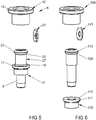
- FIG. 5 shows the shooting pin 6 for clarity FIG. 1 in an exploded view.
- the retaining collar 23 of the foot part 11 is to be produced by upsetting after the assembly of the head part 12 and the fixing element 21. Between the retaining collar 23 and the bearing collar 17, the foot part has a constriction 27.
- the constriction 27 is bounded by the two sliding surfaces 19, 20 for the fixing element 21.
- FIG. 6 shows a further embodiment of a Schl thoroughlyzapfens 106 in an exploded view.
- This embodiment is different from that FIG. 5 only in that a bearing collar 117 is arranged with a sliding surface 119 for a fixing element 121 on an insert 128.
- the insert 128 can be plugged onto a foot 111.
- the sliding surface 119 on the insert 128 together with a sliding surface 120 on a retaining collar 123 forms a radial guide for the fixing element 121.
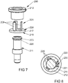
- FIG. 7 shows a further embodiment of a locking pin 206 in an exploded view.
- the locking pin 206 differs from that FIG. 6 only in that a fixing element 221 has three axial tongues 229 projecting from a circumferential bearing collar 217 and is manufactured in one piece with an insert part 228.
- a retaining collar 223 arranged at the free end of a foot part 211 has a sliding surface 220 for supporting the free ends of the tongues 229 of the fixing element 221.
- the insert 228 has on its side facing away from a head portion 212 a sliding surface 219 for support on the in FIG. 1
- the fixing element 221 is thus axially secured and rotatably mounted in the mounted state of the locking pin 206 between the retaining collar 223 and the faceplate 9.
- FIG. 8 shows the locking pin 206 FIG. 7 in the assembled state in a cross section through the head part 212 and the tongues 229 of the fixing element 221. It can be seen here that a guide 222 in the head part 212 has three axial grooves 230 for the tongues 229 of the fixing element 221.
- FIG. 9 shows a further embodiment of the locking pin 306 in an exploded view.
- a foot part 311 has a constriction 327 with two sliding surfaces 319, 320 for a bead 331 arranged on a fixing element 321.
- FIG. 10 shows a cross section through the locking pin 306 FIG. 9 in the assembled state. It can be seen here that a head part 312 has an axial guide 322 for the fixing element 321. Otherwise, the locking pin 306 is like that FIG. 5 built up.
Landscapes
- Engineering & Computer Science (AREA)
- Structural Engineering (AREA)
- Mechanical Engineering (AREA)
- Snaps, Bayonet Connections, Set Pins, And Snap Rings (AREA)
- Steps, Ramps, And Handrails (AREA)
- Power-Operated Mechanisms For Wings (AREA)
Abstract
Description
- Die Erfindung betrifft einen Schließzapfen für einen Verschluss eines Treibstangenbeschlages eines Fensters, einer Fenstertür oder dergleichen mit einem zur Befestigung in einer Treibstange des Treibstangenbeschlages vorgesehenen Fußteil, mit einem zum Eingreifen in ein Schließblech des Verschlusses vorgesehenen Kopfteil und mit einem zwischen dem Kopfteil und dem Fußteil angeordneten Fixierelement.
- Ein solcher Schließzapfen ist beispielsweise aus der
DE 20 2012 000 211 U1 bekannt. Bei diesem Schließzapfen bewirkt ein Sprengring eine formschlüssige Verriegelung eines Pilzzapfens mit einer Pilzrolle. Der Sprengring bildet damit ein Fixierelement zur Halterung der Pilzrolle an dem Pilzzapfen. Damit ist das als Pilzrolle mit dem Schließblech in Eingriff stehende Bauteil axial unverschieblich mit dem in der Treibstange zu befestigenden Pilzzapfen verbunden. Nachteilig bei diesem Schließzapfen ist jedoch, dass die Höhe der Pilzrolle nicht verstellbar ist und daher Toleranzen zwischen den Bauteilen des Fensters nicht ausgeglichen werden können. - Weiterhin ist aus der
EP 1 683 938 B1 ein Verschluss für einen Treibstangenbeschlag bekannt geworden, bei dem ein Kopfteil eine Axialführung gegenüber dem Fußteil hat. Hierdurch lässt sich die Höhe des Kopfteils durch Zug- und Druckkräfte gegenüber dem Fußteil einstellen. Hierzu hat das Kopfteil eine Übergangs- oder Presspassung in dem Fußteil. Nachteilig bei dem Verschluss ist jedoch, dass sich die Übergangs- oder Presspassung durch radial in das Kopfteil eingeleitete Kräfte lösen kann. - Der Erfindung liegt das Problem zugrunde, einen Schließzapfen der eingangs genannten Art so weiter zu bilden, dass eine zuverlässige und dauerhafte Festlegung der Höhe des Kopfteils ermöglicht wird.
- Dieses Problem wird erfindungsgemäß dadurch gelöst, dass das Fixierelement in einer axial angeordneten Führung zwischen Kopfteil und Fußteil gehalten ist und zur kraftschlüssigen Halterung der axialen Position des Kopfteils gegenüber dem Fußteil ausgebildet ist.
- Durch diese Gestaltung ermöglicht das Fixierelement den Kraftschluss in der axialen Führung. Damit lässt sich das Kopfteil in axialer Richtung gegenüber dem Fußteil verstellen. Jedoch ist die Höhe des Kopfteils gegenüber dem Fußteil zuverlässig und dauerhaft festgelegt, weil das Fixierelement in der axial angeordneten Führung gehalten ist. Die Halterung des Fixierelementes in der axialen Führung schützt die kraftschlüssige Halterung des Kopfteils vor in das Kopfteil eingeleiteten Kräften. Damit führt eine Verdrehung des Kopfteils gegenüber dem Fußteil nicht zu einer Veränderung der Kräfte, mit denen das Kopfteil axial gehalten ist.
- Eine kraftschlüssige Halterung des Kopfteils in seiner axialen Position lässt sich gemäß einer anderen vorteilhaften Weiterbildung der Erfindung einfach sicherstellen, wenn die axiale Führung im Kopfteil nutförmig zur Aufnahme des Fixierelementes gestaltet ist und wenn das Fixierelement gegen Wandungen der Führung vorgespannt ist. Weiterhin gestaltet sich die axiale Führung hierdurch konstruktiv besonders einfach.
- Die Vorspannung des Fixierelementes gegen die axiale Nut gestaltet sich gemäß einer anderen vorteilhaften Weiterbildung der Erfindung besonders einfach, wenn das Fixierelement federelastisch gestaltet ist.
- Das Kopfteil lässt sich gegenüber dem Fußteil gemäß einer anderen vorteilhaften Weiterbildung der Erfindung einfach verdrehen, die axiale Führung des Fixierelements in dem Kopfteil und eine leichtgängige Drehlagerung des Fixierelements in dem Fußteil angeordnet ist. Durch diese Gestaltung vermag das Kopfteil im montierten Zustand des Schließzapfens reibungsarm an dem Schließblech abzurollen. Damit lässt sich der Treibstangenbeschlag mit geringem Kraftaufwand und damit besonders komfortabel betätigen. Vorzugsweise stellt die Führung sicher, dass die axiale Position des Kopfteils gegenüber dem Fußteil bei einer Verdrehung des Kopfteils gehalten ist.
- Zur weiteren Vereinfachung des konstruktiven Aufbaus des Schließzapfens trägt es gemäß einer anderen vorteilhaften Weiterbildung der Erfindung bei, wenn das Fußteil zumindest eine Gleitfläche zur Abstützung des Fixierelements hat.
- Eine axiale Abstützung des Fixierelementes in einer ersten Richtung lässt sich gemäß einer anderen vorteilhaften Weiterbildung der Erfindung einfach erreichen, wenn das Fußteil an seinem freien Ende einen umlaufenden Haltebund hat und wenn die zumindest eine Gleitfläche an dem umlaufenden Haltebund angeordnet ist. Hierdurch hintergreift der umlaufende Haltebund zudem das Fixierelement und sichert es in axialer Richtung. Durch entsprechende Gestaltung des umlaufenden Haltebundes lässt sich zudem das Kopfteil hintergreifen und zuverlässig mit der Treibstange verbinden. Der Schließzapfen hat hierdurch eine besonders hohe Stabilität.
- Eine axiale Abstützung des Fixierelementes in einer zweiten Richtung lässt sich gemäß einer anderen vorteilhaften Weiterbildung der Erfindung einfach erreichen, wenn das Fußteil nahe der an der Treibstange zu befestigenden Seite einen umlaufenden Lagerbund hat und wenn die zumindest eine Gleitfläche an dem umlaufenden Lagerbund angeordnet ist.
- Die Montage des Schließzapfens gestaltet sich gemäß einer anderen vorteilhaften Weiterbildung der Erfindung besonders einfach, wenn der nahe an der Treibstange angeordnete umlaufende Lagerbund auf einem Einlegeteil angeordnet ist.
- Die Fertigung des Schließzapfens gestaltet sich gemäß einer anderen vorteilhaften Weiterbildung der Erfindung besonders einfach, wenn das Fußteil eine Einschnürung aufweist und wenn die zumindest eine Gleitfläche in der Einschnürung angeordnet ist. Vorzugsweise hat die Einschnürung zwei Gleitflächen zur Abstützung des Fixierelementes in beide axiale Richtungen.
- Der Schließzapfen gestaltet sich gemäß einer anderen vorteilhaften Weiterbildung der Erfindung konstruktiv besonders einfach, wenn das Fixierelement einen in die Einschnürung hineinragenden Wulst hat.
- Die Montage des Schließzapfens gestaltet sich gemäß einer anderen vorteilhaften Weiterbildung der Erfindung besonders einfach, wenn das Fußteil einen zur Befestigung an der Treibstange vorgesehenen Zapfen hat. Vorzugsweise wird der Zapfen in einer Bohrung der Treibstange verpresst. Durch einen Versatz der Achse des Zapfens und der Achse einer Lagerung des Kopfteils an dem Fußteil lässt sich der Schließzapfen mit einer Exzentrizität ausstatten. Mit einer solchen Exzentrizität lässt sich ein Anpressdruck des Schließzapfens gegen das Schließblech und damit eine Vorspannung des Fensters einstellen.
- Der Schließzapfen ermöglicht gemäß einer anderen vorteilhaften Weiterbildung der Erfindung einen besonders leichtgängigen Treibstangenbeschlag, wenn das Fixierelement einen umlaufenden Lagerbund zur Gleitlagerung an einer die Treibstange des Treibstangenbeschlages abdeckenden Stulpschiene hat. Weiterhin ist das Fixierelement hierdurch zuverlässig in seiner axialen Lage gehalten.
- Die Erfindung lässt zahlreiche Ausführungsformen zu. Zur weiteren Verdeutlichung ihres Grundprinzips ist eine davon in der Zeichnung dargestellt und wird nachfolgend beschrieben. Diese zeigt in
- Fig.1
- eine Schnittdarstellung eines Verschlusses,
- Fig. 2
- einen Längsschnitt durch einen Schließzapfen des Verschlusses aus
Figur 1 , - Fig. 3
- einen Querschnitt durch den Schließzapfen aus
Figur 2 entlang der Linie III - III, - Fig. 4
- einen Teilschnitt des Schließzapfens aus
Figur 2 , - Fig. 5
- eine Explosionsdarstellung des Schließzapfens aus
Figur 2 , - Fig. 6
- eine Explosionsdarstellung einer weiteren Ausführungsform des Schließzapfens,
- Fig. 7
- eine Explosionsdarstellung einer weiteren Ausführungsform des Schließzapfens,
- Fig. 8
- einen Querschnitt durch den Schließzapfen aus
Figur 7 , - Fig. 9
- eine Explosionsdarstellung einer weiteren Ausführungsform des Schließzapfens,
- Fig. 10
- einen Querschnitt durch den Schließzapfen aus
Figur 9 . -
Figur 1 zeigt einen in einem Rahmen 1 verriegelten Flügel 2 eines Fensters, einer Tür, einer Fenstertür oder dergleichen mit einem Verschluss 3 eines nicht näher dargestellten Treibstangenbeschlages 4. Der Verschluss 3 hat einen mit einer Treibstange 5 vernieteten Schließzapfen 6 und ein in dem Rahmen 1 befestigtes Schließblech 7. Zur Vernietung in der Treibstange 5 hat der Schließzapfen 6 einen zylindrischen Zapfen 8. Die Treibstange 5 ist im Flügel 2 an einer feststehenden Stulpschiene 9 längsverschieblich geführt. Die Stulpschiene 9 hat ein Langloch 10 zur Durchführung eines Fußteils 11 des Schließzapfens 6. Ein Kopfteil 12 des Schließzapfens 6 liegt mit einer Mantelfäche 13 an einer Kante 14 des Schließblechs 7 an. Weiterhin zeigtFigur 1 , dass eine Achse 15 des Fußteils 11 gegen über einer Achse 16 des Kopfteils 12 versetzt ist. Das Kopfteil 12 ist damit exzentrisch zum Fußteil 11 angeordnet. Damit lässt sich die Vorspannung der Mantelfläche 13 gegen die Kante 14 durch ein Verdrehen des Fußteils 11 gegenüber der Treibstange 5 verändern. Das Fußteil 11 hat einen umlaufenden Lagerbund 17, welcher im Betrieb des Verschlusses 3 über die Stulpschiene 9 gleitet. Das Kopfteil 12 hat einen Pilzkopf 18, welcher die Kante 14 des Schließblechs 7 hintergreift. -
Figur 2 zeigt den Schließzapfen 6 ausFigur 1 in einer vergrößerten Schnittdarstellung. Hierbei ist zu erkennen, dass das Fußteil 11 zwei umlaufende Gleitflächen 19, 20 hat, zwischen denen ein Fixierelement 21 angeordnet ist. Das Fixierelement 21 ist in einer axial angeordneten Führung 22 des Kopfteils 12 gehalten und haltert das Kopfteil 12 kraftschlüssig in der dargestellten Position. Das Kopfteil 12 lässt sich damit mittels einer vorgesehenen Kraft axial gegenüber dem Fußteil 11 verschieben und mit dem Fixierelement 21 entlang der umlaufenden Gleitflächen 19, 20 leichtgängig gegenüber dem Fußteil 11 verdrehen. Ein an dem freien Ende des Fußteils 11 angeordneter umlaufender Haltebund 23 hintergreift das Fixierelement 21 und die Führung 22 des Kopfteils 12 für das Fixierelement 21. Der umlaufende Haltebund 23 bildet damit einen Anschlag für die maximale axiale Verschiebung des Kopfteils 12 gegenüber dem Fußteil 11. Eine der umlaufenden Gleitflächen 20 ist auf dem umlaufenden Haltebund 23 angeordnet, während die andere der umlaufenden Gleitflächen 19 an dem Lagerbund 17 angeordnet ist. Das Fußteil 11 hat zudem einen Innenvielzahn 24 zum Ansetzen eines Drehwerkzeuges. Damit lässt sich die Vorspannung des Kopfteils 12 gegen die inFigur 1 dargestellte Kante 14 des Schließblechs 7 einstellen. -
Figur 3 zeigt eine Schnittdarstellung durch den Schließzapfen 6 ausFigur 2 entlang der Linie III - III. Hierbei ist zu erkennen, dass das Fixierelement 21 zwei Klemmvorsprünge 25, 26 hat, mit denen es federelastisch gegen seitliche Wandungen der axialen Führung 22 im Kopfteil 12 vorgespannt ist. -
Figur 4 zeigt einen Längsschnitt durch das Kopfteil 12 mit dem in der axialen Führung 22 eingesetzten Fixierelement 21. Das Fixierelement 21 ist länger als die Führung 22 im Kopfteil 12, so dass das Kopfteil 12 auf dem Fixierelement 21 axial verschieblich ist. Weiterhin zeigtFigur 4 , dass die Enden des Fixierelementes 21 Radien aufweisen, mit denen sie an die Gleitflächen 19, 20 des inFigur 2 dargestellten Fußteils 11 angepasst sind. -
Figur 5 zeigt zur Verdeutlichung den Schießzapfen 6 ausFigur 1 in einer Explosionsdarstellung. Der Haltebund 23 des Fußteils 11 ist erst nach der Montage des Kopfteils 12 und des Fixierelementes 21 durch Stauchen zu erzeugen. Zwischen dem Haltebund 23 und dem Lagerbund 17 hat das Fußteil eine Einschnürung 27. Die Einschnürung 27 wird von den beiden Gleitflächen 19, 20 für das Fixierelement 21 begrenzt. -
Figur 6 zeigt eine weitere Ausführungsform eines Schleißzapfens 106 in einer Explosionsdarstellung. Diese Ausführungsform unterscheidet sich von dem ausFigur 5 nur dadurch, dass ein Lagerbund 117 mit einer Gleitfläche 119 für ein Fixierelement 121 auf einem Einlegeteil 128 angeordnet ist. Zur Montage kann das Einlegeteil 128 auf einem Fußteil 111 aufgesteckt werden. Die Gleitfläche 119 auf dem Einlegeteil 128 bildet zusammen mit einer Gleitfläche 120 auf einem Haltebund 123 eine radiale Führung für das Fixierelement 121. -
Figur 7 zeigt eine weitere Ausführungsform eines Schließzapfens 206 in einer Explosionsdarstellung. Der Schließzapfen 206 unterscheidet sich von dem ausFigur 6 nur dadurch, dass ein Fixierelement 221 drei von einem umlaufenden Lagerbund 217 abstehende axiale Zungen 229 aufweist und einstückig mit einem Einlegeteil 228 gefertigt ist. Ein an dem freien Ende eines Fußteils 211 angeordneter Haltebund 223 weist eine Gleitfläche 220 zur Abstützung der freien Enden der Zungen 229 des Fixierelementes 221 auf. Das Einlegeteil 228 hat an seiner einem Kopfteil 212 abgewandten Seite eine Gleitfläche 219 zur Abstützung auf der inFigur 1 dargestellten Stulpschiene 9. Das Fixierelement 221 ist damit im montierten Zustand des Schließzapfens 206 zwischen dem Haltebund 223 und der Stulpschiene 9 axial gesichert und drehbar gelagert. -
Figur 8 zeigt den Schließzapfen 206 ausFigur 7 im montierten Zustand in einem Querschnitt durch das Kopfteil 212 und die Zungen 229 des Fixierelementes 221. Hierbei ist zu erkennen, dass eine Führung 222 im Kopfteil 212 drei axiale Nuten 230 für die Zungen 229 des Fixierelements 221 hat. -
Figur 9 zeigt eine weitere Ausführungsform des Schließzapfens 306 in einer Explosionsdarstellung. Ein Fußteil 311 weist eine Einschnürung 327 mit zwei Gleitflächen 319, 320 für einen an einem Fixierelement 321 angeordneten Wulst 331 auf. -
Figur 10 zeigt einen Querschnitt durch den Schließzapfen 306 ausFigur 9 im montierten Zustand. Hierbei ist zu erkennen, dass ein Kopfteil 312 eine axiale Führung 322 für das Fixierelement 321 hat. Ansonsten ist der Schließzapfen 306 wie der ausFigur 5 aufgebaut.
Claims (12)
- Schließzapfen (6, 106, 206, 306) für einen Verschluss (3) eines Treibstangenbeschlages (4) eines Fensters, einer Fenstertür oder dergleichen mit einem zur Befestigung in einer Treibstange (5) des Treibstangenbeschlages (4) vorgesehenen Fußteil (11, 111, 211, 311), mit einem zum Eingreifen in ein Schließblech (7) des Verschlusses (3) vorgesehenen Kopfteil (12, 112, 212, 312) und mit einem zwischen dem Kopfteil (12, 112, 212, 312) und dem Fußteil (11, 111, 211, 311) angeordneten Fixierelement (21, 121, 221, 321), dadurch gekennzeichnet, dass das Fixierelement (21, 121, 221, 321) in einer axial angeordneten Führung (22, 222, 322) zwischen Kopfteil (12, 112, 212, 312) und Fußteil (11, 111, 211, 311) gehalten ist und zur kraftschlüssigen Halterung der axialen Position des Kopfteils (12, 112, 212, 312) gegenüber dem Fußteil (11, 111, 211, 311) ausgebildet ist.
- Schließzapfen nach Anspruch 1, dadurch gekennzeichnet, dass die axiale Führung (2, 222, 322) im Kopfteil (12, 112, 212, 312) nutförmig zur Aufnahme des Fixierelementes (21, 121, 221, 321) gestaltet ist und dass das Fixierelement (21, 121, 221, 321) gegen Wandungen der Führung (2, 222, 322) vorgespannt ist.
- Schließzapfen nach Anspruch 1 oder 2, dadurch gekennzeichnet, dass das Fixierelement (21, 121, 221, 321) federelastisch gestaltet ist.
- Schließzapfen nach zumindest einem der Ansprüche 1 bis 3, dadurch gekennzeichnet, dass die axiale Führung (2, 222, 322) des Fixierelements (21, 121, 221, 321) in dem Kopfteil (12, 112, 212, 312) und eine leichtgängige Drehlagerung des Fixierelements (21, 121, 221, 321) in dem Fußteil (11, 111, 211, 311) angeordnet ist.
- Schließzapfen nach zumindest einem der Ansprüche 1 bis 4, dadurch gekennzeichnet, dass das Fußteil (11, 111, 211, 311) zumindest eine Gleitfläche (19, 20, 120, 220, 319, 320) zur Abstützung des Fixierelements (21, 121, 221, 321) hat.
- Schließzapfen nach Anspruch 5, dadurch gekennzeichnet, dass das Fußteil (11, 111, 211) an seinem freien Ende einen umlaufenden Haltebund (23, 123, 223) hat und dass die zumindest eine Gleitfläche (20, b120, 220) an dem umlaufenden Haltebund (23, 123, 223) angeordnet ist.
- Schließzapfen nach zumindest einem der Ansprüche 5 oder 6, dadurch gekennzeichnet, dass das Fußteil (11, 111, 211) nahe der an der Treibstange (5) zu befestigenden Seite einen umlaufenden Lagerbund (17, 117, 217) hat und dass die zumindest eine Gleitfläche (19, 119, 219) an dem umlaufenden Lagerbund (17, 117, 217) angeordnet ist.
- Schließzapfen nach zumindest einem der Ansprüche 1 bis 7, dadurch gekennzeichnet, dass der nahe an der Treibstange (5) angeordnete umlaufende Lagerbund (117, 217) auf einem Einlegeteil (128, 228) angeordnet ist.
- Schließzapfen nach zumindest einem der Ansprüche 5 bis 8, dadurch gekennzeichnet, dass das Fußteil (11, 311) eine Einschnürung (27, 327) aufweist und dass die zumindest eine Gleitfläche (19, 20, 319, 320) in der Einschnürung (27, 327) angeordnet ist.
- Schließzapfen nach Anspruch 9, dadurch gekennzeichnet, dass das Fixierelement (321) in die Einschnürung (327) hineinragenden Wulst (331) hat.
- Schließzapfen nach zumindest einem der Ansprüche 1 bis 10, dadurch gekennzeichnet, dass das Fußteil (11, 111, 211, 311) einen zur Befestigung an der Treibstange vorgesehenen Zapfen (8) hat.
- Schließzapfen nach zumindest einem der Ansprüche 1 bis 11, dadurch gekennzeichnet, dass das Fixierelement (21, 121, 221, 321) einen umlaufenden Lagerbund (17, 117, 217, 317) zur Gleitlagerung an einer die Treibstange (5) des Treibstangenbeschlages (4) abdeckenden Stulpschiene (9) hat.
Priority Applications (1)
| Application Number | Priority Date | Filing Date | Title |
|---|---|---|---|
| PL18212403T PL3511491T3 (pl) | 2018-01-11 | 2018-12-13 | Czop zamykający do zamknięcia okucia zasuwnicy |
Applications Claiming Priority (1)
| Application Number | Priority Date | Filing Date | Title |
|---|---|---|---|
| DE102018200416.1A DE102018200416A1 (de) | 2018-01-11 | 2018-01-11 | Schließzapfen für einen Verschluss eines Treibstangenbeschlages |
Publications (2)
| Publication Number | Publication Date |
|---|---|
| EP3511491A1 true EP3511491A1 (de) | 2019-07-17 |
| EP3511491B1 EP3511491B1 (de) | 2020-08-12 |
Family
ID=64665478
Family Applications (1)
| Application Number | Title | Priority Date | Filing Date |
|---|---|---|---|
| EP18212403.2A Active EP3511491B1 (de) | 2018-01-11 | 2018-12-13 | Schliesszapfen für einen verschluss eines treibstangenbeschlages |
Country Status (4)
| Country | Link |
|---|---|
| EP (1) | EP3511491B1 (de) |
| DE (1) | DE102018200416A1 (de) |
| ES (1) | ES2823023T3 (de) |
| PL (1) | PL3511491T3 (de) |
Citations (4)
| Publication number | Priority date | Publication date | Assignee | Title |
|---|---|---|---|---|
| DE102006000063A1 (de) * | 2006-01-27 | 2007-08-02 | Siegenia-Aubi Kg | Verschlussbolzen |
| EP2295686A1 (de) * | 2009-08-26 | 2011-03-16 | Roto Frank Ag | Schließzapfen für einen Fenster- oder Türverriegelungsbeschlag |
| DE202012000211U1 (de) | 2012-01-11 | 2012-02-23 | Selve Fenstertechnik Gmbh | Vorrichtung zum einbruchsicheren Verschließen von Fenstern und Türen |
| EP1683938B1 (de) | 2005-01-18 | 2012-11-21 | Aug. Winkhaus GmbH & Co. KG | Verschluss für einen Treibstangenbeschlag |
-
2018
- 2018-01-11 DE DE102018200416.1A patent/DE102018200416A1/de not_active Withdrawn
- 2018-12-13 PL PL18212403T patent/PL3511491T3/pl unknown
- 2018-12-13 ES ES18212403T patent/ES2823023T3/es active Active
- 2018-12-13 EP EP18212403.2A patent/EP3511491B1/de active Active
Patent Citations (4)
| Publication number | Priority date | Publication date | Assignee | Title |
|---|---|---|---|---|
| EP1683938B1 (de) | 2005-01-18 | 2012-11-21 | Aug. Winkhaus GmbH & Co. KG | Verschluss für einen Treibstangenbeschlag |
| DE102006000063A1 (de) * | 2006-01-27 | 2007-08-02 | Siegenia-Aubi Kg | Verschlussbolzen |
| EP2295686A1 (de) * | 2009-08-26 | 2011-03-16 | Roto Frank Ag | Schließzapfen für einen Fenster- oder Türverriegelungsbeschlag |
| DE202012000211U1 (de) | 2012-01-11 | 2012-02-23 | Selve Fenstertechnik Gmbh | Vorrichtung zum einbruchsicheren Verschließen von Fenstern und Türen |
Also Published As
| Publication number | Publication date |
|---|---|
| DE102018200416A1 (de) | 2019-07-11 |
| EP3511491B1 (de) | 2020-08-12 |
| ES2823023T3 (es) | 2021-05-05 |
| PL3511491T3 (pl) | 2020-12-28 |
Similar Documents
| Publication | Publication Date | Title |
|---|---|---|
| EP1978187B1 (de) | Beschlaganordnung für ein Fenster, eine Tür oder dergleichen | |
| EP2348177B1 (de) | Verschluss eines Treibstangenbeschlages | |
| EP3511491B1 (de) | Schliesszapfen für einen verschluss eines treibstangenbeschlages | |
| DE2715079C2 (de) | Riegel | |
| EP1683938B1 (de) | Verschluss für einen Treibstangenbeschlag | |
| DE102022120478A1 (de) | Betätigungshandhabe | |
| EP3363969A1 (de) | Betätigungshandhabe | |
| EP3194690B1 (de) | Beschlag für fenster, türen oder dergleichen | |
| EP3336290B1 (de) | Verschluss für eine hinterschnittene beschlagnut eines treibstangenbeschlages | |
| EP1577465B1 (de) | Schlosselement mit Befestigung für Betätigungselement | |
| DE102021201882A1 (de) | Einfache Steuerzapfenbefestigung | |
| DE202021100989U1 (de) | Beschlaganordnung für ein Fenster oder eine Tür | |
| EP1757759B1 (de) | Beschlagteil für einen Treibstangenbeschlag | |
| DE2751148A1 (de) | Auf links- oder rechts-anschlag umstellbares drehstangen-moebelschloss | |
| EP3540158A1 (de) | Schliesszapfen | |
| DE19527450A1 (de) | Bedienungsgriff | |
| DE202006009023U1 (de) | Band mit verbesserter Justierung | |
| DE2055875A1 (de) | Ausdehnbarer Stift | |
| DE3009135A1 (de) | Riegelzapfen fuer fluegelverschluesse von fenstern, tueren o.dgl. | |
| EP1141506B2 (de) | Fenster- oder türflügel | |
| DE102018106745A1 (de) | Positionieranordnung für eine Türgriffgarnitur und Türgriffgarnitur mit einer solchen Positionieranordnung | |
| DE102024202114A1 (de) | Handhabe zum Antrieb eines Treibstangenbeschlages | |
| DE102023125148A1 (de) | Vorreiberverschluss | |
| DE102020134060A1 (de) | Betätigungshandhabe für rosettenlose fenster und türen | |
| EP3006656A1 (de) | Schliesszapfen |
Legal Events
| Date | Code | Title | Description |
|---|---|---|---|
| PUAI | Public reference made under article 153(3) epc to a published international application that has entered the european phase |
Free format text: ORIGINAL CODE: 0009012 |
|
| STAA | Information on the status of an ep patent application or granted ep patent |
Free format text: STATUS: THE APPLICATION HAS BEEN PUBLISHED |
|
| AK | Designated contracting states |
Kind code of ref document: A1 Designated state(s): AL AT BE BG CH CY CZ DE DK EE ES FI FR GB GR HR HU IE IS IT LI LT LU LV MC MK MT NL NO PL PT RO RS SE SI SK SM TR |
|
| AX | Request for extension of the european patent |
Extension state: BA ME |
|
| STAA | Information on the status of an ep patent application or granted ep patent |
Free format text: STATUS: REQUEST FOR EXAMINATION WAS MADE |
|
| 17P | Request for examination filed |
Effective date: 20191216 |
|
| RBV | Designated contracting states (corrected) |
Designated state(s): AL AT BE BG CH CY CZ DE DK EE ES FI FR GB GR HR HU IE IS IT LI LT LU LV MC MK MT NL NO PL PT RO RS SE SI SK SM TR |
|
| GRAP | Despatch of communication of intention to grant a patent |
Free format text: ORIGINAL CODE: EPIDOSNIGR1 |
|
| STAA | Information on the status of an ep patent application or granted ep patent |
Free format text: STATUS: GRANT OF PATENT IS INTENDED |
|
| RIC1 | Information provided on ipc code assigned before grant |
Ipc: E05B 63/06 20060101AFI20200228BHEP Ipc: E05C 9/18 20060101ALI20200228BHEP Ipc: E05B 17/00 20060101ALN20200228BHEP |
|
| INTG | Intention to grant announced |
Effective date: 20200324 |
|
| GRAS | Grant fee paid |
Free format text: ORIGINAL CODE: EPIDOSNIGR3 |
|
| GRAA | (expected) grant |
Free format text: ORIGINAL CODE: 0009210 |
|
| STAA | Information on the status of an ep patent application or granted ep patent |
Free format text: STATUS: THE PATENT HAS BEEN GRANTED |
|
| AK | Designated contracting states |
Kind code of ref document: B1 Designated state(s): AL AT BE BG CH CY CZ DE DK EE ES FI FR GB GR HR HU IE IS IT LI LT LU LV MC MK MT NL NO PL PT RO RS SE SI SK SM TR |
|
| REG | Reference to a national code |
Ref country code: CH Ref legal event code: EP |
|
| REG | Reference to a national code |
Ref country code: IE Ref legal event code: FG4D Free format text: LANGUAGE OF EP DOCUMENT: GERMAN |
|
| REG | Reference to a national code |
Ref country code: DE Ref legal event code: R096 Ref document number: 502018002173 Country of ref document: DE |
|
| REG | Reference to a national code |
Ref country code: AT Ref legal event code: REF Ref document number: 1301695 Country of ref document: AT Kind code of ref document: T Effective date: 20200915 |
|
| REG | Reference to a national code |
Ref country code: LT Ref legal event code: MG4D |
|
| REG | Reference to a national code |
Ref country code: NL Ref legal event code: MP Effective date: 20200812 |
|
| PG25 | Lapsed in a contracting state [announced via postgrant information from national office to epo] |
Ref country code: BG Free format text: LAPSE BECAUSE OF FAILURE TO SUBMIT A TRANSLATION OF THE DESCRIPTION OR TO PAY THE FEE WITHIN THE PRESCRIBED TIME-LIMIT Effective date: 20201112 Ref country code: LT Free format text: LAPSE BECAUSE OF FAILURE TO SUBMIT A TRANSLATION OF THE DESCRIPTION OR TO PAY THE FEE WITHIN THE PRESCRIBED TIME-LIMIT Effective date: 20200812 Ref country code: HR Free format text: LAPSE BECAUSE OF FAILURE TO SUBMIT A TRANSLATION OF THE DESCRIPTION OR TO PAY THE FEE WITHIN THE PRESCRIBED TIME-LIMIT Effective date: 20200812 Ref country code: SE Free format text: LAPSE BECAUSE OF FAILURE TO SUBMIT A TRANSLATION OF THE DESCRIPTION OR TO PAY THE FEE WITHIN THE PRESCRIBED TIME-LIMIT Effective date: 20200812 Ref country code: NO Free format text: LAPSE BECAUSE OF FAILURE TO SUBMIT A TRANSLATION OF THE DESCRIPTION OR TO PAY THE FEE WITHIN THE PRESCRIBED TIME-LIMIT Effective date: 20201112 Ref country code: FI Free format text: LAPSE BECAUSE OF FAILURE TO SUBMIT A TRANSLATION OF THE DESCRIPTION OR TO PAY THE FEE WITHIN THE PRESCRIBED TIME-LIMIT Effective date: 20200812 Ref country code: GR Free format text: LAPSE BECAUSE OF FAILURE TO SUBMIT A TRANSLATION OF THE DESCRIPTION OR TO PAY THE FEE WITHIN THE PRESCRIBED TIME-LIMIT Effective date: 20201113 |
|
| PG25 | Lapsed in a contracting state [announced via postgrant information from national office to epo] |
Ref country code: RS Free format text: LAPSE BECAUSE OF FAILURE TO SUBMIT A TRANSLATION OF THE DESCRIPTION OR TO PAY THE FEE WITHIN THE PRESCRIBED TIME-LIMIT Effective date: 20200812 Ref country code: LV Free format text: LAPSE BECAUSE OF FAILURE TO SUBMIT A TRANSLATION OF THE DESCRIPTION OR TO PAY THE FEE WITHIN THE PRESCRIBED TIME-LIMIT Effective date: 20200812 Ref country code: NL Free format text: LAPSE BECAUSE OF FAILURE TO SUBMIT A TRANSLATION OF THE DESCRIPTION OR TO PAY THE FEE WITHIN THE PRESCRIBED TIME-LIMIT Effective date: 20200812 Ref country code: IS Free format text: LAPSE BECAUSE OF FAILURE TO SUBMIT A TRANSLATION OF THE DESCRIPTION OR TO PAY THE FEE WITHIN THE PRESCRIBED TIME-LIMIT Effective date: 20201212 |
|
| PG25 | Lapsed in a contracting state [announced via postgrant information from national office to epo] |
Ref country code: SM Free format text: LAPSE BECAUSE OF FAILURE TO SUBMIT A TRANSLATION OF THE DESCRIPTION OR TO PAY THE FEE WITHIN THE PRESCRIBED TIME-LIMIT Effective date: 20200812 Ref country code: EE Free format text: LAPSE BECAUSE OF FAILURE TO SUBMIT A TRANSLATION OF THE DESCRIPTION OR TO PAY THE FEE WITHIN THE PRESCRIBED TIME-LIMIT Effective date: 20200812 Ref country code: RO Free format text: LAPSE BECAUSE OF FAILURE TO SUBMIT A TRANSLATION OF THE DESCRIPTION OR TO PAY THE FEE WITHIN THE PRESCRIBED TIME-LIMIT Effective date: 20200812 Ref country code: CZ Free format text: LAPSE BECAUSE OF FAILURE TO SUBMIT A TRANSLATION OF THE DESCRIPTION OR TO PAY THE FEE WITHIN THE PRESCRIBED TIME-LIMIT Effective date: 20200812 Ref country code: DK Free format text: LAPSE BECAUSE OF FAILURE TO SUBMIT A TRANSLATION OF THE DESCRIPTION OR TO PAY THE FEE WITHIN THE PRESCRIBED TIME-LIMIT Effective date: 20200812 |
|
| REG | Reference to a national code |
Ref country code: ES Ref legal event code: FG2A Ref document number: 2823023 Country of ref document: ES Kind code of ref document: T3 Effective date: 20210505 |
|
| REG | Reference to a national code |
Ref country code: DE Ref legal event code: R097 Ref document number: 502018002173 Country of ref document: DE |
|
| PG25 | Lapsed in a contracting state [announced via postgrant information from national office to epo] |
Ref country code: AL Free format text: LAPSE BECAUSE OF FAILURE TO SUBMIT A TRANSLATION OF THE DESCRIPTION OR TO PAY THE FEE WITHIN THE PRESCRIBED TIME-LIMIT Effective date: 20200812 |
|
| PLBE | No opposition filed within time limit |
Free format text: ORIGINAL CODE: 0009261 |
|
| STAA | Information on the status of an ep patent application or granted ep patent |
Free format text: STATUS: NO OPPOSITION FILED WITHIN TIME LIMIT |
|
| PG25 | Lapsed in a contracting state [announced via postgrant information from national office to epo] |
Ref country code: SK Free format text: LAPSE BECAUSE OF FAILURE TO SUBMIT A TRANSLATION OF THE DESCRIPTION OR TO PAY THE FEE WITHIN THE PRESCRIBED TIME-LIMIT Effective date: 20200812 |
|
| 26N | No opposition filed |
Effective date: 20210514 |
|
| PG25 | Lapsed in a contracting state [announced via postgrant information from national office to epo] |
Ref country code: MC Free format text: LAPSE BECAUSE OF FAILURE TO SUBMIT A TRANSLATION OF THE DESCRIPTION OR TO PAY THE FEE WITHIN THE PRESCRIBED TIME-LIMIT Effective date: 20200812 Ref country code: SI Free format text: LAPSE BECAUSE OF FAILURE TO SUBMIT A TRANSLATION OF THE DESCRIPTION OR TO PAY THE FEE WITHIN THE PRESCRIBED TIME-LIMIT Effective date: 20200812 |
|
| PG25 | Lapsed in a contracting state [announced via postgrant information from national office to epo] |
Ref country code: IE Free format text: LAPSE BECAUSE OF NON-PAYMENT OF DUE FEES Effective date: 20201213 Ref country code: LU Free format text: LAPSE BECAUSE OF NON-PAYMENT OF DUE FEES Effective date: 20201213 |
|
| PG25 | Lapsed in a contracting state [announced via postgrant information from national office to epo] |
Ref country code: TR Free format text: LAPSE BECAUSE OF FAILURE TO SUBMIT A TRANSLATION OF THE DESCRIPTION OR TO PAY THE FEE WITHIN THE PRESCRIBED TIME-LIMIT Effective date: 20200812 Ref country code: MT Free format text: LAPSE BECAUSE OF FAILURE TO SUBMIT A TRANSLATION OF THE DESCRIPTION OR TO PAY THE FEE WITHIN THE PRESCRIBED TIME-LIMIT Effective date: 20200812 Ref country code: CY Free format text: LAPSE BECAUSE OF FAILURE TO SUBMIT A TRANSLATION OF THE DESCRIPTION OR TO PAY THE FEE WITHIN THE PRESCRIBED TIME-LIMIT Effective date: 20200812 |
|
| PG25 | Lapsed in a contracting state [announced via postgrant information from national office to epo] |
Ref country code: MK Free format text: LAPSE BECAUSE OF FAILURE TO SUBMIT A TRANSLATION OF THE DESCRIPTION OR TO PAY THE FEE WITHIN THE PRESCRIBED TIME-LIMIT Effective date: 20200812 |
|
| PG25 | Lapsed in a contracting state [announced via postgrant information from national office to epo] |
Ref country code: PT Free format text: LAPSE BECAUSE OF FAILURE TO SUBMIT A TRANSLATION OF THE DESCRIPTION OR TO PAY THE FEE WITHIN THE PRESCRIBED TIME-LIMIT Effective date: 20200812 |
|
| REG | Reference to a national code |
Ref country code: CH Ref legal event code: PL |
|
| PG25 | Lapsed in a contracting state [announced via postgrant information from national office to epo] |
Ref country code: LI Free format text: LAPSE BECAUSE OF NON-PAYMENT OF DUE FEES Effective date: 20211231 Ref country code: CH Free format text: LAPSE BECAUSE OF NON-PAYMENT OF DUE FEES Effective date: 20211231 |
|
| P01 | Opt-out of the competence of the unified patent court (upc) registered |
Effective date: 20230516 |
|
| REG | Reference to a national code |
Ref country code: DE Ref legal event code: R081 Ref document number: 502018002173 Country of ref document: DE Owner name: AUG. WINKHAUS SE & CO. KG, DE Free format text: FORMER OWNER: AUG. WINKHAUS GMBH & CO. KG, 48291 TELGTE, DE Ref country code: DE Ref legal event code: R081 Ref document number: 502018002173 Country of ref document: DE Owner name: AUG. WINKHAUS SE, DE Free format text: FORMER OWNER: AUG. WINKHAUS GMBH & CO. KG, 48291 TELGTE, DE |
|
| REG | Reference to a national code |
Ref country code: DE Ref legal event code: R081 Ref document number: 502018002173 Country of ref document: DE Owner name: AUG. WINKHAUS SE, DE Free format text: FORMER OWNER: AUG. WINKHAUS SE & CO. KG, 48291 TELGTE, DE |
|
| PGFP | Annual fee paid to national office [announced via postgrant information from national office to epo] |
Ref country code: GB Payment date: 20251218 Year of fee payment: 8 |
|
| PGFP | Annual fee paid to national office [announced via postgrant information from national office to epo] |
Ref country code: AT Payment date: 20251215 Year of fee payment: 8 |
|
| PGFP | Annual fee paid to national office [announced via postgrant information from national office to epo] |
Ref country code: FR Payment date: 20251218 Year of fee payment: 8 |
|
| PGFP | Annual fee paid to national office [announced via postgrant information from national office to epo] |
Ref country code: BE Payment date: 20251223 Year of fee payment: 8 |
|
| PGFP | Annual fee paid to national office [announced via postgrant information from national office to epo] |
Ref country code: PL Payment date: 20251202 Year of fee payment: 8 |
|
| PGFP | Annual fee paid to national office [announced via postgrant information from national office to epo] |
Ref country code: ES Payment date: 20260119 Year of fee payment: 8 |
|
| PGFP | Annual fee paid to national office [announced via postgrant information from national office to epo] |
Ref country code: DE Payment date: 20251222 Year of fee payment: 8 |
|
| PGFP | Annual fee paid to national office [announced via postgrant information from national office to epo] |
Ref country code: IT Payment date: 20251231 Year of fee payment: 8 |