EP3511452A1 - Procédé de commande d'écrans d'affichage d'une machine à filer ou à embobiner - Google Patents
Procédé de commande d'écrans d'affichage d'une machine à filer ou à embobiner Download PDFInfo
- Publication number
- EP3511452A1 EP3511452A1 EP19150135.2A EP19150135A EP3511452A1 EP 3511452 A1 EP3511452 A1 EP 3511452A1 EP 19150135 A EP19150135 A EP 19150135A EP 3511452 A1 EP3511452 A1 EP 3511452A1
- Authority
- EP
- European Patent Office
- Prior art keywords
- display
- area
- jobs
- spinning
- control
- Prior art date
- Legal status (The legal status is an assumption and is not a legal conclusion. Google has not performed a legal analysis and makes no representation as to the accuracy of the status listed.)
- Pending
Links
- 238000009987 spinning Methods 0.000 title claims abstract description 36
- 238000004804 winding Methods 0.000 title claims abstract description 31
- 238000000034 method Methods 0.000 title claims abstract description 20
- 238000012423 maintenance Methods 0.000 claims description 11
- 230000007257 malfunction Effects 0.000 description 6
- 238000004519 manufacturing process Methods 0.000 description 3
- 239000004753 textile Substances 0.000 description 3
- 230000000694 effects Effects 0.000 description 2
- 230000004308 accommodation Effects 0.000 description 1
- 230000009286 beneficial effect Effects 0.000 description 1
- 239000003086 colorant Substances 0.000 description 1
- 230000007547 defect Effects 0.000 description 1
- 239000004973 liquid crystal related substance Substances 0.000 description 1
- 230000000737 periodic effect Effects 0.000 description 1
- 238000007378 ring spinning Methods 0.000 description 1
- 239000013589 supplement Substances 0.000 description 1
Images


Classifications
-
- D—TEXTILES; PAPER
- D01—NATURAL OR MAN-MADE THREADS OR FIBRES; SPINNING
- D01H—SPINNING OR TWISTING
- D01H3/00—Spinning or twisting machines in which the product is wound-up intermittently, e.g. mules
- D01H3/02—Details
- D01H3/26—Driving or stopping arrangements not otherwise provided for; Locking motions ; Control of machines
-
- B—PERFORMING OPERATIONS; TRANSPORTING
- B65—CONVEYING; PACKING; STORING; HANDLING THIN OR FILAMENTARY MATERIAL
- B65H—HANDLING THIN OR FILAMENTARY MATERIAL, e.g. SHEETS, WEBS, CABLES
- B65H54/00—Winding, coiling, or depositing filamentary material
- B65H54/02—Winding and traversing material on to reels, bobbins, tubes, or like package cores or formers
- B65H54/22—Automatic winding machines, i.e. machines with servicing units for automatically performing end-finding, interconnecting of successive lengths of material, controlling and fault-detecting of the running material and replacing or removing of full or empty cores
-
- B—PERFORMING OPERATIONS; TRANSPORTING
- B65—CONVEYING; PACKING; STORING; HANDLING THIN OR FILAMENTARY MATERIAL
- B65H—HANDLING THIN OR FILAMENTARY MATERIAL, e.g. SHEETS, WEBS, CABLES
- B65H63/00—Warning or safety devices, e.g. automatic fault detectors, stop-motions ; Quality control of the package
- B65H63/04—Warning or safety devices, e.g. automatic fault detectors, stop-motions ; Quality control of the package responsive to excessive tension or irregular operation of apparatus
-
- D—TEXTILES; PAPER
- D01—NATURAL OR MAN-MADE THREADS OR FIBRES; SPINNING
- D01H—SPINNING OR TWISTING
- D01H13/00—Other common constructional features, details or accessories
- D01H13/14—Warning or safety devices, e.g. automatic fault detectors, stop motions ; Monitoring the entanglement of slivers in drafting arrangements
- D01H13/20—Warning or safety devices, e.g. automatic fault detectors, stop motions ; Monitoring the entanglement of slivers in drafting arrangements responsive to excessive tension or irregular operation of apparatus
-
- D—TEXTILES; PAPER
- D01—NATURAL OR MAN-MADE THREADS OR FIBRES; SPINNING
- D01H—SPINNING OR TWISTING
- D01H13/00—Other common constructional features, details or accessories
- D01H13/32—Counting, measuring, recording or registering devices
-
- G—PHYSICS
- G05—CONTROLLING; REGULATING
- G05B—CONTROL OR REGULATING SYSTEMS IN GENERAL; FUNCTIONAL ELEMENTS OF SUCH SYSTEMS; MONITORING OR TESTING ARRANGEMENTS FOR SUCH SYSTEMS OR ELEMENTS
- G05B23/00—Testing or monitoring of control systems or parts thereof
- G05B23/02—Electric testing or monitoring
- G05B23/0205—Electric testing or monitoring by means of a monitoring system capable of detecting and responding to faults
- G05B23/0259—Electric testing or monitoring by means of a monitoring system capable of detecting and responding to faults characterized by the response to fault detection
- G05B23/0267—Fault communication, e.g. human machine interface [HMI]
- G05B23/0272—Presentation of monitored results, e.g. selection of status reports to be displayed; Filtering information to the user
-
- G—PHYSICS
- G06—COMPUTING; CALCULATING OR COUNTING
- G06F—ELECTRIC DIGITAL DATA PROCESSING
- G06F3/00—Input arrangements for transferring data to be processed into a form capable of being handled by the computer; Output arrangements for transferring data from processing unit to output unit, e.g. interface arrangements
- G06F3/01—Input arrangements or combined input and output arrangements for interaction between user and computer
- G06F3/048—Interaction techniques based on graphical user interfaces [GUI]
- G06F3/0481—Interaction techniques based on graphical user interfaces [GUI] based on specific properties of the displayed interaction object or a metaphor-based environment, e.g. interaction with desktop elements like windows or icons, or assisted by a cursor's changing behaviour or appearance
- G06F3/04817—Interaction techniques based on graphical user interfaces [GUI] based on specific properties of the displayed interaction object or a metaphor-based environment, e.g. interaction with desktop elements like windows or icons, or assisted by a cursor's changing behaviour or appearance using icons
-
- G—PHYSICS
- G06—COMPUTING; CALCULATING OR COUNTING
- G06F—ELECTRIC DIGITAL DATA PROCESSING
- G06F3/00—Input arrangements for transferring data to be processed into a form capable of being handled by the computer; Output arrangements for transferring data from processing unit to output unit, e.g. interface arrangements
- G06F3/01—Input arrangements or combined input and output arrangements for interaction between user and computer
- G06F3/048—Interaction techniques based on graphical user interfaces [GUI]
- G06F3/0487—Interaction techniques based on graphical user interfaces [GUI] using specific features provided by the input device, e.g. functions controlled by the rotation of a mouse with dual sensing arrangements, or of the nature of the input device, e.g. tap gestures based on pressure sensed by a digitiser
- G06F3/0488—Interaction techniques based on graphical user interfaces [GUI] using specific features provided by the input device, e.g. functions controlled by the rotation of a mouse with dual sensing arrangements, or of the nature of the input device, e.g. tap gestures based on pressure sensed by a digitiser using a touch-screen or digitiser, e.g. input of commands through traced gestures
- G06F3/04886—Interaction techniques based on graphical user interfaces [GUI] using specific features provided by the input device, e.g. functions controlled by the rotation of a mouse with dual sensing arrangements, or of the nature of the input device, e.g. tap gestures based on pressure sensed by a digitiser using a touch-screen or digitiser, e.g. input of commands through traced gestures by partitioning the display area of the touch-screen or the surface of the digitising tablet into independently controllable areas, e.g. virtual keyboards or menus
-
- G—PHYSICS
- G06—COMPUTING; CALCULATING OR COUNTING
- G06F—ELECTRIC DIGITAL DATA PROCESSING
- G06F3/00—Input arrangements for transferring data to be processed into a form capable of being handled by the computer; Output arrangements for transferring data from processing unit to output unit, e.g. interface arrangements
- G06F3/14—Digital output to display device ; Cooperation and interconnection of the display device with other functional units
- G06F3/1423—Digital output to display device ; Cooperation and interconnection of the display device with other functional units controlling a plurality of local displays, e.g. CRT and flat panel display
-
- B—PERFORMING OPERATIONS; TRANSPORTING
- B65—CONVEYING; PACKING; STORING; HANDLING THIN OR FILAMENTARY MATERIAL
- B65H—HANDLING THIN OR FILAMENTARY MATERIAL, e.g. SHEETS, WEBS, CABLES
- B65H2701/00—Handled material; Storage means
- B65H2701/30—Handled filamentary material
- B65H2701/31—Textiles threads or artificial strands of filaments
Definitions
- the present invention relates to a method for controlling displays of a spinning or winding machine having a plurality of similar jobs and a plurality of displays, wherein each one display is assigned to several jobs. Furthermore, the invention relates to a corresponding spinning or winding machine.
- Textile machines in particular spinning or winding machines with a plurality of similar jobs, where each made a thread and / or is rewound from one sleeve to another, are known. It is also known to operate such jobs more or less independently. This independence also leads to an independent maintenance and control requirement of each individual job. For this it is necessary to provide the operating personnel with information about the respective jobs.
- the equipment of each individual spinning station with a display is associated with production-technical effort and increased costs.
- the display means described here indicates only that there is a problem at one of the two spinning stations, but not at which. This must be determined by the operating personnel.
- the object of the present invention is thus to propose a method with the aid of which a simple and cost-effective display of information relating to the respective workstations is possible without reducing the information content accessible to the operating personnel.
- each display is assigned to several jobs.
- the display displays information on several of the jobs assigned to the display, the information on the individual jobs being displayed on a partial area of the display, and if necessary the area proportion of the respective areas is changed.
- Normal operation in this context means a thread production or -spulung within regular operating parameters without interference and off commissioning or shutdown of the corresponding job.
- the proposed method saves at least every second advertisement.
- information about all the jobs associated with the display can be displayed simultaneously.
- a possible loss of information content due to the reduced display area compared to a display, which is assigned to only one workstation, is compensated by the fact that, if necessary, the area proportion of the respective partial areas can be changed. For example, in normal operation, only the most important information about each jobs assigned to the corresponding display. By contrast, when leaving the normal operation of a job, the area ratio of the partial area that is assigned to this job is increased. The enlarged area will eventually display additional information. Also could be changed by the intervention of operators of the content and / or size of the faces and thus additional information made available.
- each of the two jobs can be displayed.
- the display in normal operation indicates the state, in particular the need for maintenance, of the jobs assigned to it.
- a state could be, for example, a specific portion of a manufacturing process or, in particular, the occurrence of a defect in the operation of a job.
- information about the currently spun or rewound yarn or the progress of the ongoing spinning or winding process could be presented. It would also be conceivable that the display is switched off during normal operation of all assigned jobs and is activated only when a new state occurs at one of the assigned jobs.
- the information on the jobs associated with a display and / or the affiliation of the partial areas to the workplaces are indicated by symbols.
- symbols which are recognizable even from a long distance are of great advantage.
- symbols can also represent complex relationships in a small area. For example, an exclamation point could indicate the occurrence of a Symbolize problems, where more icons may indicate the nature of the problem.
- the affiliation of a partial area of the display to a workplace can be represented by symbols easily understandable. For example, arrows pointing in the direction of the job to which information is displayed on the corresponding subarea could unambiguously indicate this affiliation.
- the area fraction of the partial areas of a display and / or the type of information displayed by the display are changed manually if necessary or by means of a display control associated with the display, in particular due to defined states of the workplaces.
- the need described herein may occur when operators require access to information that is not displayed during normal operation of the workstations.
- a display control is advantageous, which automatically causes, for example, when errors occur at a job associated with the display, a change in the representation on a display. As a result, the operator can be efficiently informed of any necessary intervention. Alternatively, it would be conceivable to periodically change the displayed information and / or the area proportions of the partial areas at specific time intervals.
- the type of information displayed in at least one partial area of the display and / or the area ratio of at least one partial area on the total area of the display are changed by inputs to an input means associated with a display or formed by a touch-sensitive display This allows operators to easily access all information provided by the workstations.
- a touch-sensitive display in particular one or more buttons, or a keyboard and / or a mouse as input means in question.
- At least one of the work stations associated with the display is controlled by inputs to an input means associated with a display, in particular a touch-sensitive portion of the display.
- an input means associated with a display in particular a touch-sensitive portion of the display.
- Conceivable would be the change of production characteristics or adjustment of working speeds to the manual shutdown of individual jobs by appropriate inputs.
- a supplementary control by inputs in addition to a higher-level automatic control would be advantageous.
- the area proportion of a partial area on the total display area of the display is increased to at least 70% by an input and / or by a display control assigned to the display.
- a display control assigned to the display In order to present the information on a particular job clearly for the operating personnel, for example in the event of an accident, it is advantageous to increase the area ratio of the work area associated with this sub-area to a large part of the total display area. Values of 70% and higher are an advantageous measure.
- a workstation could also be temporarily assigned the entire display area.
- each with a display is assigned to several jobs, a great advantage if the display is associated with a display control, which is designed to display according to the previous or subsequent Description to control. This makes it possible to reduce the total number of displays needed versus one display per workstation without loss of operator information. For example, if two jobs are assigned to one ad each, which is controlled according to the method of the previous description, the total number of ads could be reduced by half. Further savings could result, for example, from an allocation of three or four jobs to one ad each.
- the display control is designed to control the display such that the display indicates the state, in particular the maintenance requirements of the jobs in the normal operation of their assigned jobs. This allows the operating staff in a short time an assessment of the state of the respective jobs and allows an advantageous planning of work processes.
- a major advantage for the spinning or winding machine when the display control is designed to control the display such that the information on the jobs assigned to a display and / or the affiliation of the faces of the display to the respective jobs in whole or in part Symbols are displayed. Symbols can provide a larger areal density of information than numbers and letters and are therefore particularly useful for saving display space while maintaining the same information content.
- the display control is designed to control the display such that the surface portion of the respective partial areas of the display, which are each associated with a display, are changed.
- the change in the area ratio of the individual partial areas in case of need allows, for example, the clear retrieval of additional information or alerting personnel in the event of a fault.
- the type of information displayed by the display eg, state, efficiency, maintenance history
- the display control may be changed manually or by the display control.
- the display control is designed to control the display such that the surface portions of the work areas associated with partial areas are shown in a normal operation of these jobs the same size. This facilitates the overview and the recognition of jobs outside normal operation. Alternatively, a periodic change in the size of the partial areas or a shutdown of the display during normal operation of their assigned jobs would be conceivable.
- an input device in particular a touch-sensitive section of the display, is assigned to each of the displays, by which the type of information displayed by the display in at least one partial area and / or the area ratio of at least one Part area to be changed in the total area of the display.
- an input means in particular in the immediate vicinity of the display, it is possible for the operator to retrieve additional information quickly and clearly, for example.
- a touch-sensitive portion of the display or for example a separate touch screen would be one or more buttons or a keyboard and / or mouse as input means conceivable.
- an input in particular a touch screen
- a display by which at least one workstation associated with the display is controlled.
- the possibility of on-site control facilitates maintenance and short-term adjustment of operating parameters by the operator.
- the display can immediately communicate the effects of the interventions to the operating personnel. If there is an input means for manipulating the display, it would be advantageous to use this also to control the workstations.
- the controller supplements by the input means a higher-level automatic control.
- the display controller is designed to control the display such that by input and / or automatically the area ratio of each partial area is increased to the total display area of the display to at least 70%.
- the proportion of area allocated to this work site is attributed to a large part of the display area. This serves above all the clarity and the time efficiency of the operating personnel.
- a workstation is awarded, if necessary, the entire display area or the entire proportion of the display area that displays workstation-specific information.
- an area may be provided which relates to the machine as a whole or individual sections thereof.
- the display control and / or the input means and / or the display form a unit.
- the unit of input means and display would be, for example given at a touch screen.
- An accommodation of the display control, for example, in the housing of the display would be advantageous due to the space savings.
- the displays are firmly connected to the spinning or winding machine.
- an attachment at a height of 1 m to 1.5 m above the ground would be for the operability by the staff of advantage.
- the displays may be implemented, for example, as a liquid crystal display (LCD).
- LCD liquid crystal display
- displaying different colors through the displays would be beneficial.
- the displays could in particular have a rectangular shape and, for example, edge lengths of 4 cm to 20 cm.
- the displays and / or the display controls are electronically connected to the central control of the spinning or winding machine.
- the display controller 5 can cause the enlargement of the corresponding sub-area 4 and displaying an error message, which signals to the operator if intervention is necessary.
- FIG. 2 shows the enlarged view of the display 1 in normal operation of their assigned jobs 3.
- corresponding icons for both jobs 3 easily understand the normal operation.
- the faces 4 are in this case, for example, the same size, so that the information about both jobs 3 can be displayed clearly.
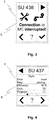
- the affiliation of the partial surfaces 4 to the respective workstations 3 is shown by way of example both by numbering and symbolically by arrows in the upper region of the display 1. By touching a touch-sensitive portion 6, for example in the lower part of the display 1 by the staff additional information about the respective job 3 can be displayed (see FIGS. 4 and 5 ).
- FIG. 3 again shows the enlarged view of the display 1, wherein here are examples of the effects of touching the in FIG. 1 displayed error message can be displayed by the staff.
- the entire display area is now assigned only the job 3 with the malfunction.
- the assignment can be clearly recognized, for example, by the designation of the workstation 3 and an arrow shown enlarged in the upper area of the display 1. Both a possible description in words and any symbolic representation that may be present specify the malfunction occurring at the workplace 3.
- FIG. 4 shows an example of additional information provided by the operator when touching the corresponding in the Figures 1 and 2 displayed fields of the touch-sensitive section 6 are called.
- the corresponding sub-area 4 is enlarged, for example, to the total area of the display 1, wherein the assignment is preferably recognizable in the upper area of the display 1 by way of example by the name of the workstation 3 and symbolically by an arrow.
- An overview shows general information about the status of job 3, such as the work step in which it is located or the efficiency with which it works. This clearly shows that the variable size of the partial surfaces 4 prevents an information and overview loss while simultaneously saving on the number of displays 1, since the display 1 behaves temporarily, for example, as if it were only assigned to a single workstation 3.
- the staff can call, for example, more detailed information on the status of the workstation 3 or change into other categories (see FIG. 5 ).
- FIG. 5 An example of another category of additional information shows FIG. 5 , Here are exemplary maintenance information about the workplace 3 shown. These include, for example, the time of the last malfunction or the accumulated downtime of the job 3. By touching a corresponding field of the touch-sensitive portion 6, the operator can call, for example, a menu for manual control of the job 3. As a result, the job 3 could be shut down, for example, on site. By touching other fields detailed information can be called up or changed to other categories as before.
Landscapes
- Engineering & Computer Science (AREA)
- Theoretical Computer Science (AREA)
- General Engineering & Computer Science (AREA)
- Human Computer Interaction (AREA)
- Physics & Mathematics (AREA)
- General Physics & Mathematics (AREA)
- Quality & Reliability (AREA)
- Mechanical Engineering (AREA)
- Textile Engineering (AREA)
- Automation & Control Theory (AREA)
- Spinning Or Twisting Of Yarns (AREA)
- Filamentary Materials, Packages, And Safety Devices Therefor (AREA)
Applications Claiming Priority (1)
| Application Number | Priority Date | Filing Date | Title |
|---|---|---|---|
| DE102018100362.5A DE102018100362A1 (de) | 2018-01-09 | 2018-01-09 | Verfahren zum Steuern von Anzeigen einer Spinn- oder Spulmaschine |
Publications (1)
| Publication Number | Publication Date |
|---|---|
| EP3511452A1 true EP3511452A1 (fr) | 2019-07-17 |
Family
ID=64949177
Family Applications (1)
| Application Number | Title | Priority Date | Filing Date |
|---|---|---|---|
| EP19150135.2A Pending EP3511452A1 (fr) | 2018-01-09 | 2019-01-03 | Procédé de commande d'écrans d'affichage d'une machine à filer ou à embobiner |
Country Status (5)
| Country | Link |
|---|---|
| US (1) | US11078603B2 (fr) |
| EP (1) | EP3511452A1 (fr) |
| JP (1) | JP2019135343A (fr) |
| CN (1) | CN110016740B (fr) |
| DE (1) | DE102018100362A1 (fr) |
Cited By (1)
| Publication number | Priority date | Publication date | Assignee | Title |
|---|---|---|---|---|
| EP3757264A1 (fr) * | 2019-06-19 | 2020-12-30 | Maschinenfabrik Rieter AG | Procédé de fonctionnement d'un métier à filer à filetage croisé partiellement ou entièrement automatique |
Families Citing this family (2)
| Publication number | Priority date | Publication date | Assignee | Title |
|---|---|---|---|---|
| DE102019116475A1 (de) * | 2019-06-18 | 2020-12-24 | Saurer Spinning Solutions Gmbh & Co. Kg | Optimierung des Betriebes einer Spinnmaschine |
| DE102021127096A1 (de) | 2021-10-19 | 2023-04-20 | Maschinenfabrik Rieter Ag | Kreuzspulenherstellende Textilmaschine mit einer Vielzahl gleichartiger, nebeneinander angeordneter Arbeitsstellen und einer entlang der Arbeitsstellen verfahrbaren Bedieneinrichtung sowie Verfahren zum Betreiben einer solchen kreuzspulenherstellenden Textilmaschine |
Citations (3)
| Publication number | Priority date | Publication date | Assignee | Title |
|---|---|---|---|---|
| JPS61100807A (ja) * | 1984-10-20 | 1986-05-19 | Fanuc Ltd | Faシステムにおける画像表示方法 |
| EP1065303A1 (fr) * | 1999-07-02 | 2001-01-03 | Rieter Ingolstadt Spinnereimaschinenbau AG | Machine textile avec plusieurs station de travail similaires |
| EP2826899A1 (fr) * | 2013-07-17 | 2015-01-21 | Saurer Germany GmbH & Co. KG | Métier à filer continu à anneaux équipé d'un capteur de détection du mouvement du curseur |
Family Cites Families (9)
| Publication number | Priority date | Publication date | Assignee | Title |
|---|---|---|---|---|
| JPH0460740A (ja) * | 1990-06-28 | 1992-02-26 | Fuji Xerox Co Ltd | ネットワークシステム |
| US5631825A (en) * | 1993-09-29 | 1997-05-20 | Dow Benelux N.V. | Operator station for manufacturing process control system |
| JPH07300278A (ja) * | 1994-05-09 | 1995-11-14 | Murata Mach Ltd | ワインダの管理装置 |
| DE19923047A1 (de) * | 1999-05-20 | 2000-11-23 | Rieter Ingolstadt Spinnerei | Verfahren und Vorrichtung zur Steuerung einer Komponente einer eine Vielzahl gleichartiger Arbeitstellen nebeneinander aufweisenden Textilmaschine |
| DE102006045237A1 (de) * | 2006-09-26 | 2008-04-03 | Oerlikon Textile Gmbh & Co. Kg | Spulmaschine |
| EP2026154A1 (fr) * | 2007-08-09 | 2009-02-18 | Siemens Aktiengesellschaft | Dispositif de commande pour contrôler une machine-outil, une machine de production et/ou une machine conçue sous forme de robot |
| TR201807072T4 (tr) * | 2013-10-01 | 2018-06-21 | Rieter Ag Maschf | İpli̇k temi̇zleyi̇ci̇si̇ ve bi̇r eği̇rme maki̇nesi̇ni̇n bununla donatilmiş olan eği̇rme i̇stasyonu ve bi̇r eği̇rme i̇stasyonunun çaliştirilmasi i̇çi̇n yöntem. |
| DE102017110572A1 (de) * | 2016-05-25 | 2017-11-30 | Oerlikon Textile Gmbh & Co. Kg | Verfahren zur Überwachung und Bedienung einer Mehrzahl von Schmelzspinnstellen sowie eine Schmelzspinnanlage mit mehreren Schmelzspinnstellen |
| DE102016007779A1 (de) * | 2016-06-24 | 2017-12-28 | Saurer Germany Gmbh & Co. Kg | Verfahren zum Überwachen des ordnungsgemäßen Arbeitens der Spinnstellen einer Ringspinnmaschine |
-
2018
- 2018-01-09 DE DE102018100362.5A patent/DE102018100362A1/de active Pending
- 2018-12-24 CN CN201811581315.4A patent/CN110016740B/zh active Active
-
2019
- 2019-01-03 EP EP19150135.2A patent/EP3511452A1/fr active Pending
- 2019-01-08 JP JP2019001252A patent/JP2019135343A/ja active Pending
- 2019-01-08 US US16/242,559 patent/US11078603B2/en active Active
Patent Citations (3)
| Publication number | Priority date | Publication date | Assignee | Title |
|---|---|---|---|---|
| JPS61100807A (ja) * | 1984-10-20 | 1986-05-19 | Fanuc Ltd | Faシステムにおける画像表示方法 |
| EP1065303A1 (fr) * | 1999-07-02 | 2001-01-03 | Rieter Ingolstadt Spinnereimaschinenbau AG | Machine textile avec plusieurs station de travail similaires |
| EP2826899A1 (fr) * | 2013-07-17 | 2015-01-21 | Saurer Germany GmbH & Co. KG | Métier à filer continu à anneaux équipé d'un capteur de détection du mouvement du curseur |
Cited By (1)
| Publication number | Priority date | Publication date | Assignee | Title |
|---|---|---|---|---|
| EP3757264A1 (fr) * | 2019-06-19 | 2020-12-30 | Maschinenfabrik Rieter AG | Procédé de fonctionnement d'un métier à filer à filetage croisé partiellement ou entièrement automatique |
Also Published As
| Publication number | Publication date |
|---|---|
| DE102018100362A1 (de) | 2019-07-11 |
| US20190211480A1 (en) | 2019-07-11 |
| US11078603B2 (en) | 2021-08-03 |
| JP2019135343A (ja) | 2019-08-15 |
| CN110016740B (zh) | 2022-12-30 |
| CN110016740A (zh) | 2019-07-16 |
Similar Documents
| Publication | Publication Date | Title |
|---|---|---|
| EP2126681B1 (fr) | Dispositif et procédé de représentation visuelle d'une information d'état d'un processus technique sur plusieurs écrans | |
| EP3511452A1 (fr) | Procédé de commande d'écrans d'affichage d'une machine à filer ou à embobiner | |
| DE10105668B4 (de) | Internet-Inline-Steuereinrichtung für eine Strickmaschine | |
| DE112008000499T5 (de) | Verfahren zum Laden und Anzeigen verschiedener Prozessanzeigen auf einem Benutzerinterface eines industriellen Kontrollsystems | |
| CH703401B1 (de) | Verfahren und Vorrichtung zum Erzeugen einer Benutzerschnittstelle zum Bedienen von Maschinen. | |
| EP2430504B1 (fr) | Système de gestion d'alarme | |
| EP3760772A1 (fr) | Optimisation du fonctionnement d'un métier à filer | |
| EP2316051A1 (fr) | Dispositif d'affichage électronique, installation utilisant les techniques d'automatisation, ainsi que procédé d'exploitation d'un dispositif d'affichage électronique | |
| DE102019106285A1 (de) | Verfahren zum automatischen Ausrichten eines Fensters innerhalb einer Benutzeroberfläche | |
| EP1460499A1 (fr) | Interface de commande pour une machine outil | |
| DE102016123235A1 (de) | Betriebsverwaltungssystem zum direkten anzeigen eines arbeitsbefehls auf basis einer betriebsverwaltungsinformation an einer werkzeugmaschine | |
| DE102013108104B4 (de) | Verfahren und Kontrollvorrichtung für die Kontrolle einer Wickelvorrichtung | |
| DE10250442A1 (de) | Vorrichtung zur Herstellung und/oder Bearbeiten synthetischer Fäden sowie ein Verfahren zum Steuern einer derartigen Vorrichtung | |
| EP2893409B1 (fr) | Interface utilisateur et procédé pour remédier à des dysfonctionnements d'une installation industrielle | |
| EP3246441B1 (fr) | Installation de fabrication de tissus en mailles jetees et procede de commande d'une installation de fabrication de tissus en mailles jetees | |
| EP3517470B1 (fr) | Procédé de fonctionnement d'une machine à filer ou à embobiner | |
| EP0770946B1 (fr) | Procédé pour concevoir automatiquement la redondance optimale pour des mesures dans le système de controle des centrales électriques | |
| EP3361366A1 (fr) | Procédé et appareil d'activation automatique de cases à cocher | |
| DE102011113301A1 (de) | Bedienungsgerät für eine Produktionsanlage oder eine Maschine | |
| EP3637211B1 (fr) | Procédé de fonctionnement d'une installation ainsi qu'une installation | |
| EP0511941A1 (fr) | Dispositif pour la commande d'une installation de filature ou d'un métier à filer | |
| EP2495693A1 (fr) | Procédé de traitement de flottes de chariots de manutention | |
| EP2450846A1 (fr) | Procédé et dispositif destinés à la sélection de types d'acier | |
| EP3960918A1 (fr) | Dispositif de fonctionnement pour une machine textile et procédé de fonctionnement d'une machine textile | |
| DE102011115904A1 (de) | Graphische Benutzerschnittstelle |
Legal Events
| Date | Code | Title | Description |
|---|---|---|---|
| PUAI | Public reference made under article 153(3) epc to a published international application that has entered the european phase |
Free format text: ORIGINAL CODE: 0009012 |
|
| STAA | Information on the status of an ep patent application or granted ep patent |
Free format text: STATUS: THE APPLICATION HAS BEEN PUBLISHED |
|
| AK | Designated contracting states |
Kind code of ref document: A1 Designated state(s): AL AT BE BG CH CY CZ DE DK EE ES FI FR GB GR HR HU IE IS IT LI LT LU LV MC MK MT NL NO PL PT RO RS SE SI SK SM TR |
|
| AX | Request for extension of the european patent |
Extension state: BA ME |
|
| STAA | Information on the status of an ep patent application or granted ep patent |
Free format text: STATUS: REQUEST FOR EXAMINATION WAS MADE |
|
| 17P | Request for examination filed |
Effective date: 20200115 |
|
| RBV | Designated contracting states (corrected) |
Designated state(s): AL AT BE BG CH CY CZ DE DK EE ES FI FR GB GR HR HU IE IS IT LI LT LU LV MC MK MT NL NO PL PT RO RS SE SI SK SM TR |
|
| STAA | Information on the status of an ep patent application or granted ep patent |
Free format text: STATUS: EXAMINATION IS IN PROGRESS |
|
| 17Q | First examination report despatched |
Effective date: 20220829 |
|
| GRAP | Despatch of communication of intention to grant a patent |
Free format text: ORIGINAL CODE: EPIDOSNIGR1 |
|
| STAA | Information on the status of an ep patent application or granted ep patent |
Free format text: STATUS: GRANT OF PATENT IS INTENDED |