EP2026154A1 - Dispositif de commande pour contrôler une machine-outil, une machine de production et/ou une machine conçue sous forme de robot - Google Patents
Dispositif de commande pour contrôler une machine-outil, une machine de production et/ou une machine conçue sous forme de robot Download PDFInfo
- Publication number
- EP2026154A1 EP2026154A1 EP07015724A EP07015724A EP2026154A1 EP 2026154 A1 EP2026154 A1 EP 2026154A1 EP 07015724 A EP07015724 A EP 07015724A EP 07015724 A EP07015724 A EP 07015724A EP 2026154 A1 EP2026154 A1 EP 2026154A1
- Authority
- EP
- European Patent Office
- Prior art keywords
- operating
- window
- machine
- application
- control buttons
- Prior art date
- Legal status (The legal status is an assumption and is not a legal conclusion. Google has not performed a legal analysis and makes no representation as to the accuracy of the status listed.)
- Withdrawn
Links
- 238000004519 manufacturing process Methods 0.000 title claims description 8
- 238000013461 design Methods 0.000 description 3
- 238000003754 machining Methods 0.000 description 2
- 238000003825 pressing Methods 0.000 description 2
- TVEXGJYMHHTVKP-UHFFFAOYSA-N 6-oxabicyclo[3.2.1]oct-3-en-7-one Chemical compound C1C2C(=O)OC1C=CC2 TVEXGJYMHHTVKP-UHFFFAOYSA-N 0.000 description 1
- 239000002826 coolant Substances 0.000 description 1
- 230000001419 dependent effect Effects 0.000 description 1
- 238000011017 operating method Methods 0.000 description 1
- 238000012549 training Methods 0.000 description 1
- 238000012800 visualization Methods 0.000 description 1
Images
Classifications
-
- G—PHYSICS
- G05—CONTROLLING; REGULATING
- G05B—CONTROL OR REGULATING SYSTEMS IN GENERAL; FUNCTIONAL ELEMENTS OF SUCH SYSTEMS; MONITORING OR TESTING ARRANGEMENTS FOR SUCH SYSTEMS OR ELEMENTS
- G05B19/00—Programme-control systems
- G05B19/02—Programme-control systems electric
- G05B19/18—Numerical control [NC], i.e. automatically operating machines, in particular machine tools, e.g. in a manufacturing environment, so as to execute positioning, movement or co-ordinated operations by means of programme data in numerical form
- G05B19/409—Numerical control [NC], i.e. automatically operating machines, in particular machine tools, e.g. in a manufacturing environment, so as to execute positioning, movement or co-ordinated operations by means of programme data in numerical form characterised by using manual data input [MDI] or by using control panel, e.g. controlling functions with the panel; characterised by control panel details or by setting parameters
-
- G—PHYSICS
- G05—CONTROLLING; REGULATING
- G05B—CONTROL OR REGULATING SYSTEMS IN GENERAL; FUNCTIONAL ELEMENTS OF SUCH SYSTEMS; MONITORING OR TESTING ARRANGEMENTS FOR SUCH SYSTEMS OR ELEMENTS
- G05B2219/00—Program-control systems
- G05B2219/30—Nc systems
- G05B2219/36—Nc in input of data, input key till input tape
- G05B2219/36015—Display areas, fields on screen correspond to position of keys on panel, matrix
-
- G—PHYSICS
- G05—CONTROLLING; REGULATING
- G05B—CONTROL OR REGULATING SYSTEMS IN GENERAL; FUNCTIONAL ELEMENTS OF SUCH SYSTEMS; MONITORING OR TESTING ARRANGEMENTS FOR SUCH SYSTEMS OR ELEMENTS
- G05B2219/00—Program-control systems
- G05B2219/30—Nc systems
- G05B2219/36—Nc in input of data, input key till input tape
- G05B2219/36146—Group windows into coherent sets to facilate a task
-
- G—PHYSICS
- G05—CONTROLLING; REGULATING
- G05B—CONTROL OR REGULATING SYSTEMS IN GENERAL; FUNCTIONAL ELEMENTS OF SUCH SYSTEMS; MONITORING OR TESTING ARRANGEMENTS FOR SUCH SYSTEMS OR ELEMENTS
- G05B2219/00—Program-control systems
- G05B2219/30—Nc systems
- G05B2219/36—Nc in input of data, input key till input tape
- G05B2219/36147—Limit number of windows displayed simultaneously
Definitions
- the invention relates to an operating device for operating a machine tool, production machine and / or designed as a robot machine.
- the invention has for its object to enable easy operation of a machine tool, production machine and / or designed as a robot machine.
- an operating device for operating a machine tool, production machine and / or a machine designed as a robot, wherein the operating device has a screen, wherein the screen at the same time a first and a second operating window can be visualized, wherein a first application for operating the machine in the first operating window is visualized, a second application for operating the machine in the second operating window is visualized, wherein the operation of the first application by means of the first operating window assigned first control buttons, wherein the Operation of the second application by means of the second operating window associated second control buttons, wherein the first control buttons along a single or multiple pages of the first control window are arranged, wherein the second control buttons along a single or more sides of the second control window are arranged.
- a first, second, third and fourth operating window can be visualized, with a first application for operating the machine in the first operating window is visualized, a second application for operating the machine in the second operating window visualized wherein a third application for operating the machine in the third operating window can be visualized, wherein a fourth application for operating the machine in the fourth operating window is visualized, wherein the operation of the first application by means of the first operating window assigned first control buttons, wherein the operation the second application by means of the second operating window assigned second control buttons, wherein the operation of the third application by means of the third control window associated third control buttons, wherein the operation of the fourth application by means of the fourth control window vi associated
- the first control buttons are arranged along a single or multiple sides of the first control window, wherein the second control buttons are arranged along a single or multiple sides of the second control window, wherein the third control buttons along a single or multiple sides of the third control window, wherein the fourth control buttons are arranged along a single or multiple sides
- the operating device has common control buttons for operating the machine, wherein an operating window can be selected from the control windows and can be assigned to the common control buttons.
- the operating device can thus also have so-called common control buttons in addition to permanently assigned control buttons, which corresponds to a, e.g. can be assigned by means of a selection button, selected operating window.
- the screen is designed as a touch-sensitive screen, wherein the control buttons or part of the control buttons are an integral part of the screen.
- An embodiment of the control buttons as conventional mechanical buttons can thus be omitted or at least partially eliminated, which allows a simpler structure of the operating device.
- the selection button and the common control buttons can be an integral part of the screen.
- a touch-sensitive screen allows quick and direct selection of the operating window (for example by pressing on the operating window to be selected).
- control buttons are located outside the screen, since the control buttons can then be designed to be particularly stable. Furthermore, an ergonomic design of the control buttons and / or a design of the control buttons with tactility (tactile feedback to the operator) allows.
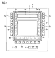
- FIG. 1 is shown in the form of a schematic representation of a first embodiment of the control device according to the invention.
- the operating device 1 has a screen 2, whereby a first operating window 3a and a second operating window 3b are simultaneously visualized by the screen 2.
- a first application 4a for operating the machine in the first operating window 3a is visualized in the first operating window 3a, and at the same time a second application 4b for operating the machine is visualized in the second operating window 3b.
- the first application 4a can be present, for example, in the form of applications, for example, of the machine manufacturer, such as representing functions relating to the coolant supply of the machine or the chip conveyance. With the aid of the first application, the operator can then parameterize the necessary parameters, for example.
- the second application 4b may include, for example, the operation of control functionalities of the machining process.
- control parameters such as the rotational speed of a tool
- the second application 4b can thus be present, for example, in the form of a user interface for the control functionalities.
- the operation of the first application 4a takes place by means of the first operating window 3a associated first control buttons 5a and the operation of the second application 4b is carried out by means of the second control window 3b associated second control buttons 5b takes place.
- the first control buttons 5a and the second control buttons 5b are arranged along several sides of the second control window 3b.
- the individual control buttons are in FIG. 1 Shown schematically in the form of square boxes. Due to the fixed assignment of the operating keys along a single or several pages of a respective associated operating window, a simple and clear operation of the machine is made possible for the operator. Furthermore, the operator can operate within a screen display both the first application 4a and the second application 4b and have in mind without them, as usual in commercial machines, with the help of eg a menu to call one after the other.
- the first operating keys 5a are arranged on the left and right sides along the first operating window 3a and the second operating keys 5b are arranged along three sides of the second operating window 3b.
- the control buttons only on a single page of a control window. This depends on the required number of control buttons for the respective application.
- FIG. 1 an embodiment of the invention is shown in which two applications are served. Of course, it is also possible, even more applications (eg, three, four, five, six, etc.) analogous to the scheme according to FIG. 1 to visualize.
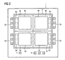
- FIG. 2 is an example of an embodiment of the invention, in which four applications are visualized simultaneously, shown in FIG. 2 the same elements are provided with the same reference numerals as in FIG. 1 ,
- a first operating window 3a, a second operating window 3b, a third operating window 3c and a fourth operating window 3d are visualized from the screen 2 of the operating device 1, wherein a first application 4a for operating the machine is visualized in the first operating window 3a with a second application 4b for operating the machine being visualized in the second operating window 3b, a third application 4c for operating the machine being visualized in the third operating window 3c, a fourth application 4d for operating the machine in the fourth operating window 3d wherein the operation of the first application 4a by means of the first operating window 3a assigned first control buttons 5a, wherein the operation of the second application 4b by means of the second control window 3b assigned second control buttons 5b takes place, the operation of the third application 4c by means of the third control window 3c associated with the third application keys 5c, wherein the operation of the fourth application 4d by means of the fourth control window 3d assigned fourth control buttons 5d takes place, the first control buttons 5a along a single side of the first control window 3
- control buttons but also, depending on the need for number of control buttons, be arranged along multiple pages of the respective associated control window.
- the screen 2 is divided into two parts by the representation of the operating window on the screen, while in training according to FIG. 2 the screen 2, according to the four operating windows, is divided into four parts.
- the screen 2 can thus be divided according to the number of operating windows.
- the operating device can be what is in FIG. 1 and FIG. 2 is shown, in addition to the already described, the respective operating window firmly assigned control buttons, so-called common control buttons 6, which can be assigned by means of a selection button 7 one of the existing operating window.
- the selection button 7 is pressed for this purpose, for example, several times for a short time, wherein after each pressing operation another operating window increasingly lights up and signals in such a way that the relevant operating window and thus the application visualized in the operating window has been selected. Subsequently, an operation of the thus selected application, by means of the common control buttons 6, take place.
- the control buttons 6 can be used for example for input of parameters.
- the selection button 7 can also be an integral part of a computer mouse.
- the screen 2 can also be designed as a touch-sensitive screen (touch screen), in which case the control buttons or a part of the control buttons can be an integral part of the screen.
- touch screen touch screen
- control buttons 5a ', 5b', 5c 'and 5d' are shown, which may alternatively or additionally be provided to the outside of the screen 2 arranged control buttons 5a, 5b, 5c and 5d.
- selection button 7 and the common control buttons 6 can be an integral part of the screen.
- the operating device can not only have a single but also several screens with control buttons, with respect to the screens, an operation and visualization of applications, according to the invention, takes place in analog form. It should be noted at this point that, of course, in the case of a control device with multiple screens, from each screen, only a single application can be visualized.
Landscapes
- Engineering & Computer Science (AREA)
- Human Computer Interaction (AREA)
- Manufacturing & Machinery (AREA)
- Physics & Mathematics (AREA)
- General Physics & Mathematics (AREA)
- Automation & Control Theory (AREA)
- Numerical Control (AREA)
- Manipulator (AREA)
- User Interface Of Digital Computer (AREA)
Priority Applications (3)
| Application Number | Priority Date | Filing Date | Title |
|---|---|---|---|
| EP07015724A EP2026154A1 (fr) | 2007-08-09 | 2007-08-09 | Dispositif de commande pour contrôler une machine-outil, une machine de production et/ou une machine conçue sous forme de robot |
| JP2008201875A JP2009043257A (ja) | 2007-08-09 | 2008-08-05 | 工作機械、生産機械、又はロボットとして形成された機械の操作装置 |
| US12/189,463 US20090046066A1 (en) | 2007-08-09 | 2008-08-11 | Operating device for operating a machine tool, a production machine and/or a machine in the form of a robot |
Applications Claiming Priority (1)
| Application Number | Priority Date | Filing Date | Title |
|---|---|---|---|
| EP07015724A EP2026154A1 (fr) | 2007-08-09 | 2007-08-09 | Dispositif de commande pour contrôler une machine-outil, une machine de production et/ou une machine conçue sous forme de robot |
Publications (1)
| Publication Number | Publication Date |
|---|---|
| EP2026154A1 true EP2026154A1 (fr) | 2009-02-18 |
Family
ID=38896927
Family Applications (1)
| Application Number | Title | Priority Date | Filing Date |
|---|---|---|---|
| EP07015724A Withdrawn EP2026154A1 (fr) | 2007-08-09 | 2007-08-09 | Dispositif de commande pour contrôler une machine-outil, une machine de production et/ou une machine conçue sous forme de robot |
Country Status (3)
| Country | Link |
|---|---|
| US (1) | US20090046066A1 (fr) |
| EP (1) | EP2026154A1 (fr) |
| JP (1) | JP2009043257A (fr) |
Families Citing this family (2)
| Publication number | Priority date | Publication date | Assignee | Title |
|---|---|---|---|---|
| DE102010024345B4 (de) | 2010-06-18 | 2017-02-16 | Airbus Defence and Space GmbH | Bedieneinrichtung mit einer Mehrzahl von neben- und/oder untereinander angeordneten Betätigungselementen sowie Luftfahrzeug |
| DE102018100362A1 (de) * | 2018-01-09 | 2019-07-11 | Maschinenfabrik Rieter Ag | Verfahren zum Steuern von Anzeigen einer Spinn- oder Spulmaschine |
Citations (5)
| Publication number | Priority date | Publication date | Assignee | Title |
|---|---|---|---|---|
| JPS61100807A (ja) * | 1984-10-20 | 1986-05-19 | Fanuc Ltd | Faシステムにおける画像表示方法 |
| EP0342591A2 (fr) * | 1988-05-16 | 1989-11-23 | Mitsubishi Denki Kabushiki Kaisha | Système de formation de données d'usinage pour dispositif à commande numérique |
| WO1999030221A1 (fr) * | 1997-11-25 | 1999-06-17 | Saab Automobile Ab | Tableau de commande |
| US6236399B1 (en) * | 1997-02-26 | 2001-05-22 | Amada Company, Limited | Display method for information setting screen along process flow and a multi-window type NC apparatus having such function |
| WO2001096969A1 (fr) * | 2000-06-16 | 2001-12-20 | Husky Injection Molding Systems Ltd. | Procede permettant de simplifier le fonctionnement d'une machine |
Family Cites Families (13)
| Publication number | Priority date | Publication date | Assignee | Title |
|---|---|---|---|---|
| GB9201949D0 (en) * | 1992-01-30 | 1992-03-18 | Jenkin Michael | Large-scale,touch-sensitive video display |
| US5712995A (en) * | 1995-09-20 | 1998-01-27 | Galileo Frames, Inc. | Non-overlapping tiling apparatus and method for multiple window displays |
| US6476833B1 (en) * | 1999-03-30 | 2002-11-05 | Koninklijke Philips Electronics N.V. | Method and apparatus for controlling browser functionality in the context of an application |
| JP3329804B2 (ja) * | 2000-02-21 | 2002-09-30 | 株式会社東芝 | 監視制御装置 |
| US7287232B2 (en) * | 2000-05-08 | 2007-10-23 | Fujitsu Limited | Information display system having graphical user interface switchingly controlling information display on display screen |
| GB0114458D0 (en) * | 2001-06-14 | 2001-08-08 | Lucas Industries Ltd | An in-vehicle display system |
| JP3839295B2 (ja) * | 2001-10-09 | 2006-11-01 | 株式会社ジェイテクト | 設備モニタ装置 |
| DE10203370A1 (de) * | 2002-01-29 | 2003-07-31 | Siemens Ag | Verfahren zur Steuerung einer fensterorientierten Bedienoberfläche und ein HMI Gerät zur Durchführung des Verfahrens |
| US7343566B1 (en) * | 2002-07-10 | 2008-03-11 | Apple Inc. | Method and apparatus for displaying a window for a user interface |
| CA2574351C (fr) * | 2004-07-23 | 2010-06-15 | Learning Tree International | Systeme et procede de presentations electroniques |
| JP2007025808A (ja) * | 2005-07-12 | 2007-02-01 | Canon Inc | 仮想キーボードシステム及びその制御方法 |
| US7777731B2 (en) * | 2006-10-13 | 2010-08-17 | Siemens Medical Solutions Usa, Inc. | System and method for selection of points of interest during quantitative analysis using a touch screen display |
| US8843828B2 (en) * | 2007-05-31 | 2014-09-23 | International Business Machines Corporation | Web page backup across multiple windows |
-
2007
- 2007-08-09 EP EP07015724A patent/EP2026154A1/fr not_active Withdrawn
-
2008
- 2008-08-05 JP JP2008201875A patent/JP2009043257A/ja not_active Withdrawn
- 2008-08-11 US US12/189,463 patent/US20090046066A1/en not_active Abandoned
Patent Citations (5)
| Publication number | Priority date | Publication date | Assignee | Title |
|---|---|---|---|---|
| JPS61100807A (ja) * | 1984-10-20 | 1986-05-19 | Fanuc Ltd | Faシステムにおける画像表示方法 |
| EP0342591A2 (fr) * | 1988-05-16 | 1989-11-23 | Mitsubishi Denki Kabushiki Kaisha | Système de formation de données d'usinage pour dispositif à commande numérique |
| US6236399B1 (en) * | 1997-02-26 | 2001-05-22 | Amada Company, Limited | Display method for information setting screen along process flow and a multi-window type NC apparatus having such function |
| WO1999030221A1 (fr) * | 1997-11-25 | 1999-06-17 | Saab Automobile Ab | Tableau de commande |
| WO2001096969A1 (fr) * | 2000-06-16 | 2001-12-20 | Husky Injection Molding Systems Ltd. | Procede permettant de simplifier le fonctionnement d'une machine |
Also Published As
| Publication number | Publication date |
|---|---|
| JP2009043257A (ja) | 2009-02-26 |
| US20090046066A1 (en) | 2009-02-19 |
Similar Documents
| Publication | Publication Date | Title |
|---|---|---|
| EP2077474B1 (fr) | Dispositif de commande et procédé d'assignation d'un écran de commande à une touche programmable | |
| EP0768588A2 (fr) | Console de commande et méthode de préparation et d'ajustement d'un engin mobile de travail | |
| DE102014000972A1 (de) | Betriebsprogrammschreibsystem | |
| DE102007013979A1 (de) | Modulare Tastatur für ein elektronisches Gerät und Verfahren zum Betreiben derselben | |
| DE10325894A1 (de) | Werkzeug-oder Produktionsmaschine mit Anzeigeeinheit zur Visualisierung von Arbeitsabläufen | |
| DE20210814U1 (de) | Schalteinrichtung zum gemeinsamen Schalten einer Tastatur, eines Bildschirms und einer Maus | |
| EP3064050A1 (fr) | Systeme de controle d'un appareil de travail agricole | |
| EP0412308B1 (fr) | Calculateur électronique ayant une représentation des fonctions des touches programmables | |
| DE10308816A1 (de) | Ikone und Schrittikonendarstellung zur graphischen Visualisierung von aufgabenorientierten Schritten | |
| DE102016103700A1 (de) | Steuerkonsole | |
| AT513665B1 (de) | Bedieneinheit für eine Spritzgießmaschine | |
| DE10359251A1 (de) | Vorrichtung zur Automatisierung von Werkzeug- oder Produktionsmaschinen | |
| EP2026154A1 (fr) | Dispositif de commande pour contrôler une machine-outil, une machine de production et/ou une machine conçue sous forme de robot | |
| EP0718994A2 (fr) | Dispositif pour le traitement de siganux audibles | |
| EP0858016A1 (fr) | Dispositif de contrÔle numérique avec interface de travail utilisant des fenêtres | |
| DE3843454C1 (fr) | ||
| DE10161924A1 (de) | Verfahren zur Zweihandbedienung einer flächigen Anzeige- und Bedieneinheit, mit berührungssensitivem Display, HMI Gerät, Automatisierungssystem und Computerprogrammprodukt zur Durchführung des Verfahrens | |
| EP1315057A1 (fr) | Dispositif et procédé de création et/ou de modification de programmes CN ou de tables CN | |
| DE102018100364A1 (de) | Verfahren zum Betreiben einer Spinn- oder Spulmaschine | |
| EP2893409A1 (fr) | Interface utilisateur et procédé pour remédier à des dysfonctionnements d'une installation industrielle | |
| EP3656495B1 (fr) | Optimiser l'interface utilisateur d'un appareil de soudage | |
| DE102019008515A1 (de) | Informationsverarbeitungsvorrichtung | |
| DE102013216347A1 (de) | Bedienvorrichtung und Verfahren zum Steuern zumindest einer Maschine | |
| EP2645229A1 (fr) | Traitement d'étapes de travail d'un procédé de fabrication de produits d'impression | |
| EP2921921A1 (fr) | Procédé de fonctionnement d'un système de commande d'un appareil d'automatisation |
Legal Events
| Date | Code | Title | Description |
|---|---|---|---|
| PUAI | Public reference made under article 153(3) epc to a published international application that has entered the european phase |
Free format text: ORIGINAL CODE: 0009012 |
|
| AK | Designated contracting states |
Kind code of ref document: A1 Designated state(s): AT BE BG CH CY CZ DE DK EE ES FI FR GB GR HU IE IS IT LI LT LU LV MC MT NL PL PT RO SE SI SK TR |
|
| AX | Request for extension of the european patent |
Extension state: AL BA HR MK RS |
|
| 17P | Request for examination filed |
Effective date: 20090706 |
|
| AKX | Designation fees paid |
Designated state(s): AT BE BG CH CY CZ DE DK EE ES FI FR GB GR HU IE IS IT LI LT LU LV MC MT NL PL PT RO SE SI SK TR |
|
| 17Q | First examination report despatched |
Effective date: 20100630 |
|
| STAA | Information on the status of an ep patent application or granted ep patent |
Free format text: STATUS: THE APPLICATION IS DEEMED TO BE WITHDRAWN |
|
| 18D | Application deemed to be withdrawn |
Effective date: 20101111 |