EP3510265B1 - Zweitaktverbrennungsmotor - Google Patents
Zweitaktverbrennungsmotor Download PDFInfo
- Publication number
- EP3510265B1 EP3510265B1 EP17755254.4A EP17755254A EP3510265B1 EP 3510265 B1 EP3510265 B1 EP 3510265B1 EP 17755254 A EP17755254 A EP 17755254A EP 3510265 B1 EP3510265 B1 EP 3510265B1
- Authority
- EP
- European Patent Office
- Prior art keywords
- duct
- section
- cylinder
- scavenging
- engine
- Prior art date
- Legal status (The legal status is an assumption and is not a legal conclusion. Google has not performed a legal analysis and makes no representation as to the accuracy of the status listed.)
- Active
Links
Images




Classifications
-
- F—MECHANICAL ENGINEERING; LIGHTING; HEATING; WEAPONS; BLASTING
- F02—COMBUSTION ENGINES; HOT-GAS OR COMBUSTION-PRODUCT ENGINE PLANTS
- F02B—INTERNAL-COMBUSTION PISTON ENGINES; COMBUSTION ENGINES IN GENERAL
- F02B25/00—Engines characterised by using fresh charge for scavenging cylinders
- F02B25/14—Engines characterised by using fresh charge for scavenging cylinders using reverse-flow scavenging, e.g. with both outlet and inlet ports arranged near bottom of piston stroke
-
- F—MECHANICAL ENGINEERING; LIGHTING; HEATING; WEAPONS; BLASTING
- F02—COMBUSTION ENGINES; HOT-GAS OR COMBUSTION-PRODUCT ENGINE PLANTS
- F02B—INTERNAL-COMBUSTION PISTON ENGINES; COMBUSTION ENGINES IN GENERAL
- F02B33/00—Engines characterised by provision of pumps for charging or scavenging
- F02B33/02—Engines with reciprocating-piston pumps; Engines with crankcase pumps
- F02B33/04—Engines with reciprocating-piston pumps; Engines with crankcase pumps with simple crankcase pumps, i.e. with the rear face of a non-stepped working piston acting as sole pumping member in co-operation with the crankcase
-
- F—MECHANICAL ENGINEERING; LIGHTING; HEATING; WEAPONS; BLASTING
- F02—COMBUSTION ENGINES; HOT-GAS OR COMBUSTION-PRODUCT ENGINE PLANTS
- F02B—INTERNAL-COMBUSTION PISTON ENGINES; COMBUSTION ENGINES IN GENERAL
- F02B33/00—Engines characterised by provision of pumps for charging or scavenging
- F02B33/02—Engines with reciprocating-piston pumps; Engines with crankcase pumps
- F02B33/28—Component parts, details or accessories of crankcase pumps, not provided for in, or of interest apart from, subgroups F02B33/02 - F02B33/26
-
- F—MECHANICAL ENGINEERING; LIGHTING; HEATING; WEAPONS; BLASTING
- F02—COMBUSTION ENGINES; HOT-GAS OR COMBUSTION-PRODUCT ENGINE PLANTS
- F02B—INTERNAL-COMBUSTION PISTON ENGINES; COMBUSTION ENGINES IN GENERAL
- F02B63/00—Adaptations of engines for driving pumps, hand-held tools or electric generators; Portable combinations of engines with engine-driven devices
- F02B63/02—Adaptations of engines for driving pumps, hand-held tools or electric generators; Portable combinations of engines with engine-driven devices for hand-held tools
-
- F—MECHANICAL ENGINEERING; LIGHTING; HEATING; WEAPONS; BLASTING
- F02—COMBUSTION ENGINES; HOT-GAS OR COMBUSTION-PRODUCT ENGINE PLANTS
- F02F—CYLINDERS, PISTONS OR CASINGS, FOR COMBUSTION ENGINES; ARRANGEMENTS OF SEALINGS IN COMBUSTION ENGINES
- F02F1/00—Cylinders; Cylinder heads
- F02F1/002—Integrally formed cylinders and cylinder heads
-
- F—MECHANICAL ENGINEERING; LIGHTING; HEATING; WEAPONS; BLASTING
- F02—COMBUSTION ENGINES; HOT-GAS OR COMBUSTION-PRODUCT ENGINE PLANTS
- F02F—CYLINDERS, PISTONS OR CASINGS, FOR COMBUSTION ENGINES; ARRANGEMENTS OF SEALINGS IN COMBUSTION ENGINES
- F02F1/00—Cylinders; Cylinder heads
- F02F1/18—Other cylinders
- F02F1/22—Other cylinders characterised by having ports in cylinder wall for scavenging or charging
-
- F—MECHANICAL ENGINEERING; LIGHTING; HEATING; WEAPONS; BLASTING
- F02—COMBUSTION ENGINES; HOT-GAS OR COMBUSTION-PRODUCT ENGINE PLANTS
- F02B—INTERNAL-COMBUSTION PISTON ENGINES; COMBUSTION ENGINES IN GENERAL
- F02B75/00—Other engines
- F02B75/02—Engines characterised by their cycles, e.g. six-stroke
- F02B2075/022—Engines characterised by their cycles, e.g. six-stroke having less than six strokes per cycle
- F02B2075/025—Engines characterised by their cycles, e.g. six-stroke having less than six strokes per cycle two
Definitions
- the present invention regards two-stroke internal combustion engines, in particular two-stroke engines intended to actuate small work equipment such as for example chainsaws, string trimmers and the like.
- two-stroke engines may comprise at least one cylinder within which there is slidably received a piston that divides the interior volume of the cylinder into two distinct chambers; a combustion chamber and a pumping chamber.
- An air and fuel mixture whose combustion produces exhaust gases in rapid expansion causing the movement of the piston before flowing out through an exhaust duct, is periodically introduced into the combustion chamber.
- the comburent air is generally supplied through an intake duct, which places the pumping chamber in communication with the external environment.
- the amount of air introduced into the pumping chamber can be regulated by means of a power valve, typically a butterfly valve, which is arranged in the intake duct and it can be activated from the external so as to vary the opening degree thereof.
- a power valve typically a butterfly valve
- the fuel is normally supplied by means of a carburettor, which comprises a venturi pipe arranged along the intake duct, typically upstream of the power valve, and a dispensing nozzle which terminates into the venturi pipe and which is in communication with a fuel tank.
- a carburettor which comprises a venturi pipe arranged along the intake duct, typically upstream of the power valve, and a dispensing nozzle which terminates into the venturi pipe and which is in communication with a fuel tank.
- the airflow which flows along the venturi pipe generates a depression which, through the dispensing nozzle, intakes the fuel from the tank and mixes it with the air directed towards the pumping chamber.
- the air and fuel mixture which gathers in the pumping chamber is subsequently pushed into the combustion chamber thanks to the movement of the piston, which forces it to flow through a series of scavenging ducts which place the pumping chamber in communication with the combustion chamber.
- These scavenging ducts are generally open at the end of the expansion stroke of the piston, when the exhaust duct is open, so that the air and fuel mixture facilitates the cleaning of the cylinder, i.e. it pushes the combustion gases to flow out of the exhaust duct.
- Each scavenging duct generally comprises an initial portion exiting from the pumping chamber, extending parallel to the cylinder, and a terminal portion terminating in the combustion chamber, extending transversely towards the cylinder.
- Such engines are for example known from US 2005/0133189 A1 or EP 2463495 A2 .
- the cross-section of the terminal portion is substantially constant or slightly convergent towards the cylinder, so as to accelerate and direct the air and fuel mixture towards the interior of the combustion chamber.
- An object of the present invention is to overcome or at least reduce this drawback of the prior art through a solution that is simple, rational and inexpensive.
- the terminal portion of the scavenging duct widens progressively moving from the inlet section towards the outlet section.
- the inlet section of the terminal portion may define a choke in the scavenging duct.
- the inlet section may be narrower not only as regards all the passage sections of the terminal portion, but also all the passage sections of at least the scavenging duct that is immediately upstream with respect thereto (with respect to the direction of flow of the mixture).
- the flow of the air and fuel mixture that flows along the scavenging duct is accelerated at the initial section of the terminal portion i.e. the choke, and then projected into the combustion chamber at a higher speed.
- the inlet section of the terminal portion may be the narrowest passage section of the entire scavenging duct.
- the area of the inlet section of the terminal portion may be smaller than the area of all the other passage sections of the scavenging duct.
- the acceleration of the air and fuel mixture can be advantageously obtained without excessively increasing pressure drop.
- the projection of the terminal portion of the scavenging duct on a median plane containing the axis of the cylinder is fully contained in the projection of the outlet section on the same median plane.
- the terminal portion of the scavenging duct has no undercut surface with respect to the aforementioned median plane, thus enabling obtaining the engine by means of a casting process, in a relatively simple and inexpensive manner.
- this solution enables obtaining the engine by means of a die-casting process, which advantageously allows reducing costs, thickness and tolerances with respect to the normal casting processes, for example sand casting.
- the aforementioned solution enables obtaining the interior wall of the terminal portion of the scavenging duct by means of a core (or insert) which can be advantageously extracted, at the end of the casting process, through just one straight motion in the perpendicular direction with respect to the median plane.
- the aforementioned median plane is a symmetry plane of the exhaust duct and, optionally, may be a symmetry plane of the intake duct.
- the outlet section of the terminal portion of the scavenging duct may be substantially rectangular-shaped.
- This embodiment enables a more accurate opening/closure of the scavenging duct by the piston sleeve, during the various engine duty cycles.
- a cross-section of the terminal portion of the scavenging duct carried out according to a section plane orthogonal to the central axis of the cylinder, is substantially trapezoidal-shaped.
- This embodiment enables a better distribution of the air and fuel mixture in the combustion chamber.
- the aforementioned cross-section has a side substantially orthogonal to the median plane.
- This solution facilitates the manufacturing of the engine by means of the die-casting process and it also enables nearing the terminal portion of the scavenging duct to the exhaust opening.
- the engine may comprise at least one pair of said scavenging ducts (which are shaped and arranged in a mutually symmetrical manner with respect to said median plane.
- This solution enables making the cleaning of the cylinder as well as the loading of the air and fuel mixture into the combustion chamber more uniform and efficient.
- an internal combustion engine 100 in particular a two-stroke internal combustion engine intended to actuate small work equipment such as for example chainsaws, string trimmers, blowers and the like.
- the engine 100 comprises an outer body which can be made up of a casing 110 and a cylinder head 115 which is fixed to the casing 110, for example by means of screws.
- crank chamber 120 inside the casing 110 there is defined a crank chamber 120, in which there is received a crank 125 suitable to rotate around a pre-set rotational axis A.
- the crank 125 may be made in a single piece with the rotating shaft 130, which is generally referred to as a crankshaft and whose axis coincides with the rotational axis A.
- a cylinder 135, which terminates at one end in the crank chamber 120 while it is closed at the opposite end by a head wall 140.
- the cylinder 135 extends longitudinally along a central axis B, which can be orthogonal and/or coplanar with the rotational axis A of the crank 125.
- a piston 145 which divides the interior volume into two separate chambers, including a combustion chamber 150 defined between the piston 145 and the head wall 140, and a pumping chamber 155 defined on the opposite side of the piston 145 and communicating with the crank chamber 120.
- the separation between the combustion chamber 150 and the pumping chamber 155 may be improved by one or more sealing rings coaxially interposed between the sleeve of the piston 145 and the interior surface of the cylinder 135.
- a spark plug (not illustrated), which may be inserted into a reception hole 105 and it is capable of igniting a spark in the combustion chamber 150.
- an intake duct 160 which is suitable to supply an air and fuel mixture into the pumping chamber 155.
- this intake duct 160 may extend longitudinally according to a central axis C which can be coplanar and/or orthogonal to the central axis B of the cylinder 135.
- the intake duct 160 may extend with an almost constant passage section up to an outlet section 165, which may be substantially rectangular-shaped and can be obtained on interior surface of the cylinder 135.
- the air and fuel mixture may be supplied through a conventional carburettor system (not illustrated), which can be connected to the intake duct 160.
- the carburettor may have the characteristics explained and described in the introduction.
- an exhaust duct 170 which is suitable to convey the combustion gases produced in the combustion chamber 150 to the external.
- This exhaust duct 170 extends longitudinally according to a central axis D which can be coplanar and/or orthogonal to the central axis B of the cylinder 135.
- the exhaust duct 170 may extend with an almost constant passage section starting from an inlet section 175, which may be substantially rectangular-shaped and can be obtained on interior surface of the cylinder 135.
- the inlet section 175 of the exhaust duct 170 is generally at least partly positioned at a greater height, i.e. closer to the head wall 140 of the cylinder 135, with respect to the outlet section 165 of the intake duct 160.
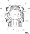
- a first pair of scavenging ducts 180 which can be configured and arranged in a perfectly symmetrical manner with respect to a median plane M containing the central axis B of the cylinder 135 and, in the embodiment illustrated in the attached figures, also containing the central axes C and D respectively of the intake duct 160 and the exhaust duct 170.
- the median plane M is a symmetry plane not only of the cylinder 135, but also of the exhaust duct 170 and, optionally, of the intake duct 160.
- each of these scavenging ducts 180 comprises a first section 185 exiting from the pumping chamber 155, generally through the crank chamber 120 (also see fig. 2 ), which may extend in the direction substantially parallel to the central axis B of the cylinder 135, and a second portion 190 terminating in the combustion chamber 150, which may extend in the direction substantially transverse with respect to the central axis B.
- the first portion 185 may be configured as a blind cavity which extends starting from an inlet section 195 towards an opposite closed end.
- the inlet section may be obtained on a surface of the cylinder head 115 that is orthogonal to the central axis B of the cylinder 135 and which is suitable to remain exposed in the crank chamber 120 when the cylinder head 115 is joined to the casing 110.
- the first portion 185 may have a converging configuration in which the area of the passage section, made with respect to a plane orthogonal to the central axis B of the cylinder 135, decreases progressively starting from the inlet section 195 towards the closed end.
- the second portion 190 laterally derives from the first portion 185, for example at the closed end of the latter, and extends up to the inner surface of the cylinder 135.
- the second portion 190 has an inlet section 200 which is defined at the intersection between the second portion 190 and the first portion 185, and an opposite outlet section 205 which is directly obtained on the interior surface of the cylinder 135.
- the second portion 190 has a diverging configuration in which the area of the passage section increases progressively starting from the inlet section 200 towards the outlet section 205.
- the projection of the second portion 190, i.e. of the inlet section 200 thereof, on the median plane M is fully contained in the projection of the outlet section 205 on the same median plane M.
- the second section 190 of the scavenging duct 180 does not have any undercut surface with respect to the median plane M, enabling obtaining the cylinder head 115 through a casting process, for example a die-casting process.
- this solution enables obtaining the interior wall of the terminal portion of the scavenging duct by means of a core (or insert) which can be advantageously extracted, at the end of the casting process, through just one straight motion in the perpendicular direction with respect to the median plane M.
- the outlet section 205 of the second portion 190 may be substantially rectangular-shaped and it can be positioned at a higher height, i.e. closer to the head wall 140 of the cylinder 135, with respect to the outlet section 165 of the intake duct 160, for example at a height comprised between the outlet section 165 of the intake duct and the inlet section 175 of the exhaust duct 170.
- the inlet section 200 of the second portion 190 may be dimensioned according to the bore or displacement capacity of the engine 100 and it can be the narrowest passage section of the entire scavenging duct 180.
- the inlet section 200 may be smaller than the area of all the other passage sections of the scavenging duct 180, both in the first portion 185 and in the second portion 190.
- the inlet section 200 creates some sort of choke of the scavenging duct 180 hence enabling accelerating the mass of air and fuel that traverses it.
- a cross-section of the second portion 190 of the scavenging duct 180 carried out according to a section plane orthogonal to the central axis B of the cylinder 135, is substantially perimeter shaped to form trapezium, whose greater base may coincide with the profile of the outlet section 205 while the smaller base may coincide with the profile of the inlet section 200.
- the side of the trapezium proximal to the exhaust duct 170 is substantially orthogonal to the median plane M; it may be inclined with respect to the orthogonal so as to be non-undercut with respect to the median plane M, for example about 1°.
- This solution enables maintaining the outlet section 205 of the scavenging duct 180 very close to the inlet section 175 of the exhaust duct 170, without interference.
- the side of the trapezium distal from the exhaust duct 170 may instead have a greater inclination than the proximal side, but still in the non-undercut direction with respect to the median plane M.
- the cross-section of the first portion 185 may be generally rectangular-shaped having a greater side from which the second portion 190 derives.
- the width of this greater side of the first portion 185 is greater than the width of the inlet section 200 of the second portion 190, so that between them there is defined a triangular notch projecting on the opposite side with respect to the exhaust duct 170.
- the angle at the vertex of this notch may be an acute angle, for example comprised between 40° and 70°, preferably equal to 55°.
- the side of the notch facing the first portion 185 of the scavenging duct 180 may have a substantially arched section profile with its center on the central axis B of cylinder 135, or may have a substantially rectilinear section profile but tangent to an imaginary circumference centered on the central axis B of cylinder 135.
- in the cylinder head 115 of the engine 100 may also be obtained in a second pair of scavenging ducts 210, which are arranged distant from the exhaust duct 170 with respect to the scavenging ducts 180.
- the scavenging ducts 210 may be configured and arranged in a perfectly symmetrical manner with respect to the median plane M.
- Each of these further scavenging ducts 210 may have shapes and dimensions partly different from the scavenging ducts 180 but they reproduce all previously described technical characteristics thereof, which will not be repeated herein but will still be deemed valid also as concerns the second scavenging ducts 210.
- the fresh air and fuel mixture coming from the intake duct 160 is intaken into the pumping chamber 155 due to the depression created by the piston 145 each time the latter performs an ascent stroke towards the head wall 140 which closes the cylinder 135 (see fig. 2 ). While the piston 145 performs this ascent stroke, the air and fuel mixture already present in the combustion chamber 150 is simultaneously compressed.
- the spark plug is controlled to generate a spark that ignites the combustion of the air and fuel mixture.
- the combustion of the air and fuel mixture produces exhaust gases in rapid expansion that push the piston 145 to perform a descent stroke moving away from the head wall 140 of the cylinder 135.
- the piston 145 firstly opens the inlet section 175 of the exhaust duct 170 to enable the exhaust gases to flow out towards the external environment, then it opens the outlet section 205 of the scavenging ducts 180 and 210, and then it closes the outlet section 165 of the intake duct 160.
- the piston 145 pumps the mixture previously intaken into the pumping chamber 155 into the scavenging ducts 180 and 210 and from there to the combustion chamber 150.
- this mixture flow is accelerated at the choke defined by the inlet section 200 and projected into the combustion chamber 150 at a high speed.
- the mixture flow maintains a compact front and strong directionality, separating from the diverging walls of the second portion 190 of the scavenging duct 180.
- the mixture flow penetrates deeply into the combustion chamber 50, reducing the amount of fuel that could flow out directly from the exhaust duct 170 unburnt.
- the piston 145 Upon reaching the bottom dead centre position, i.e. the position where the volume of the combustion chamber 150 is maximum, the piston 145 starts a new ascent stroke.
- the piston 145 firstly closes the outlet section 205 of the scavenging ducts 180 and 210 and the exhaust duct 170 and then progressively reduces the volume of the combustion chamber 150, compressing the air and fuel mixture contained therein, so that the cycle can restart anew.
Landscapes
- Engineering & Computer Science (AREA)
- Chemical & Material Sciences (AREA)
- Combustion & Propulsion (AREA)
- Mechanical Engineering (AREA)
- General Engineering & Computer Science (AREA)
- Cylinder Crankcases Of Internal Combustion Engines (AREA)
- Supercharger (AREA)
Claims (6)
- Zweitakt-Verbrennungsmotor (100), umfassend:- einen Zylinder (135), der eine voreingestellte Mittelachse (B) aufweist,- einen Kolben (145), der verschiebbar mit dem Zylinder (135) gekoppelt und geeignet ist, das Innenvolumen des Zylinders (135) in zwei verschiedene Kammern zu unterteilen; eine Brennkammer (150) und eine Pumpenkammer (155),- einen Einlasskanal (160) in Kommunikation mit der Pumpenkammer (155),- einen Auslasskanal (170) in Kommunikation mit der Brennkammer (150), und- mindestens einen Spülkanal (180), der geeignet ist, die Pumpenkammer (155) in Kommunikation mit der Brennkammer (150) zu bringen,wobei der Spülkanal (180) einen Endabschnitt (190) aufweist, der zu der Brennkammer (150) führt, die sich mit einer Konfiguration erstreckt, die von einem Einlassabschnitt (200) bis zu einem Auslassabschnitt (205), der an einer Seitenfläche des Zylinders (135) erlangt wird, divergiert, und
wobei die Projektion des Endabschnitts (190) des Spülkanals (180) auf einer Mittelebene (M), die die Achse (B) des Zylinders (135) enthält, vollständig in der Projektion des Auslassabschnitts (205) auf derselben Mittelebene (M) enthalten ist, wobei die Mittelebene (M) eine Symmetrieebene des Auslasskanals (170) ist,
wobei der Querschnitt des Endabschnitts (190) des Spülkanals (180), der gemäß einer Schnittebene orthogonal zu der Mittelachse (B) des Zylinders (135) ausgeführt ist, im Wesentlichen trapezförmig ist,
dadurch gekennzeichnet, dass der Querschnitt eine Seite proximal zu dem Auslasskanal (170) aufweist, die im Wesentlichen orthogonal zu der Mittelebene (M) ist. - Motor (100) nach Anspruch 1, wobei der Einlassabschnitt (200) des Endabschnitts (190) eine Drossel in dem Spülkanal (180) definiert.
- Motor (100) nach Anspruch 2, wobei der Einlassabschnitt (200) des Endabschnitts (190) der engste Durchgangsabschnitt des gesamten Spülkanals (180) ist.
- Motor (100) nach einem der vorherigen Ansprüche, wobei die Mittelebene (M) eine Symmetrieebene des Einlasskanals (160) ist.
- Motor (100) nach einem der vorherigen Ansprüche, wobei der Auslassabschnitt (205) des Endabschnitts (190) des Spülkanals (180) im Wesentlichen rechteckig ist.
- Motor (100) nach einem der vorherigen Ansprüche, umfassend mindestens ein Paar der Spülkanäle (180), die auf eine zueinander symmetrische Weise in Bezug auf die Mittelebene (M) geformt und angeordnet sind.
Priority Applications (1)
| Application Number | Priority Date | Filing Date | Title |
|---|---|---|---|
| PL17755254T PL3510265T3 (pl) | 2016-09-08 | 2017-07-25 | Dwusuwowy silnik o spalaniu wewnętrznym |
Applications Claiming Priority (2)
| Application Number | Priority Date | Filing Date | Title |
|---|---|---|---|
| IT102016000090851A IT201600090851A1 (it) | 2016-09-08 | 2016-09-08 | Motore a combustione interna due tempi |
| PCT/IB2017/054509 WO2018047024A1 (en) | 2016-09-08 | 2017-07-25 | Two-stroke internal combustion engine |
Publications (2)
| Publication Number | Publication Date |
|---|---|
| EP3510265A1 EP3510265A1 (de) | 2019-07-17 |
| EP3510265B1 true EP3510265B1 (de) | 2020-08-26 |
Family
ID=57796865
Family Applications (1)
| Application Number | Title | Priority Date | Filing Date |
|---|---|---|---|
| EP17755254.4A Active EP3510265B1 (de) | 2016-09-08 | 2017-07-25 | Zweitaktverbrennungsmotor |
Country Status (7)
| Country | Link |
|---|---|
| US (1) | US10767550B2 (de) |
| EP (1) | EP3510265B1 (de) |
| CN (1) | CN109690047B (de) |
| ES (1) | ES2830950T3 (de) |
| IT (1) | IT201600090851A1 (de) |
| PL (1) | PL3510265T3 (de) |
| WO (1) | WO2018047024A1 (de) |
Families Citing this family (3)
| Publication number | Priority date | Publication date | Assignee | Title |
|---|---|---|---|---|
| JP1660392S (de) * | 2019-07-22 | 2020-06-01 | ||
| WO2022129988A1 (es) * | 2020-12-15 | 2022-06-23 | Emilio Bartolome Gonzalez | Motor de combustión interna de cuatro tiempos mejorado |
| CN113107662A (zh) * | 2021-05-08 | 2021-07-13 | 永康市茂金园林机械有限公司 | 一种用于分层扫气二冲程发动机的汽缸活塞单元 |
Family Cites Families (8)
| Publication number | Priority date | Publication date | Assignee | Title |
|---|---|---|---|---|
| JPS58155114A (ja) * | 1983-02-17 | 1983-09-14 | Kioritz Corp | 2サイクルエンジン用鋳造シリンダの掃気口形成方法 |
| CN85203399U (zh) * | 1985-02-22 | 1986-07-02 | 皮亚乔公司 | 二冲程发动机的气缸 |
| JPH04330329A (ja) * | 1991-04-30 | 1992-11-18 | Sanshin Ind Co Ltd | クランク室予圧縮式2サイクル内燃機関 |
| JP4082868B2 (ja) * | 2001-02-05 | 2008-04-30 | 株式会社共立 | 2サイクル内燃エンジン |
| JP3910955B2 (ja) * | 2003-12-22 | 2007-04-25 | 株式会社共立 | インサート中子及びそれを用いた内燃エンジン用シリンダの製造方法 |
| CN200952421Y (zh) * | 2006-09-13 | 2007-09-26 | 山东华盛农业药械股份有限公司 | 一种二冲程汽油机 |
| JP5780888B2 (ja) * | 2010-12-13 | 2015-09-16 | 株式会社やまびこ | 2サイクルエンジン |
| CN103573383B (zh) * | 2013-11-20 | 2016-01-13 | 怡天技动力机械研发(临沂)有限公司 | 一种二冲程发动机 |
-
2016
- 2016-09-08 IT IT102016000090851A patent/IT201600090851A1/it unknown
-
2017
- 2017-07-25 EP EP17755254.4A patent/EP3510265B1/de active Active
- 2017-07-25 CN CN201780055450.2A patent/CN109690047B/zh active Active
- 2017-07-25 WO PCT/IB2017/054509 patent/WO2018047024A1/en not_active Ceased
- 2017-07-25 US US16/324,345 patent/US10767550B2/en active Active
- 2017-07-25 ES ES17755254T patent/ES2830950T3/es active Active
- 2017-07-25 PL PL17755254T patent/PL3510265T3/pl unknown
Non-Patent Citations (1)
| Title |
|---|
| None * |
Also Published As
| Publication number | Publication date |
|---|---|
| US20190170054A1 (en) | 2019-06-06 |
| CN109690047A (zh) | 2019-04-26 |
| CN109690047B (zh) | 2022-03-11 |
| IT201600090851A1 (it) | 2018-03-08 |
| US10767550B2 (en) | 2020-09-08 |
| ES2830950T3 (es) | 2021-06-07 |
| EP3510265A1 (de) | 2019-07-17 |
| PL3510265T3 (pl) | 2021-02-08 |
| WO2018047024A1 (en) | 2018-03-15 |
Similar Documents
| Publication | Publication Date | Title |
|---|---|---|
| US4362132A (en) | Two-cycle engine | |
| EP3510265B1 (de) | Zweitaktverbrennungsmotor | |
| CN101230792A (zh) | 具有流量调节文丘里喷嘴的发动机曲轴箱强制通风系统 | |
| CN100489282C (zh) | 直喷式二冲程发动机 | |
| CN103867289A (zh) | 用于内燃发动机的可变进气歧管及其可变进气设备 | |
| JPH0988617A (ja) | 2サイクルエンジン | |
| EP0894967A3 (de) | Kolben für eine Brennkraftmaschine | |
| US5960749A (en) | Two-cycle internal combustion engine | |
| GB1433147A (en) | Multistage combustion process for internal combustion engines | |
| EP1009925B1 (de) | Zweitaktbrennkraftmaschine mit verbessertem brennstofffluss durch spülkanäle | |
| KR102011888B1 (ko) | 내연기관용 유체흐름 조절장치 및 이를 포함하는 체크밸브 | |
| JP2009002311A (ja) | 2サイクルエンジン | |
| US8235021B2 (en) | Device for supplying an internal combustion engine | |
| US3074388A (en) | Two-cycle cross-flow internal combustion engine with fuel injection | |
| US11525467B2 (en) | Method of gas exchange for four-stroke engine | |
| JPH06193446A (ja) | 副室式ディーゼル機関 | |
| US6530349B2 (en) | Two-cycle internal combustion engine | |
| TW201538840A (zh) | 二衝程引擎 | |
| CN215566203U (zh) | 一种用于活塞式航空发动机的排气喷管 | |
| JPH02286820A (ja) | 副燃焼室式2サイクルディーゼルエンジン | |
| KR0131128Y1 (ko) | 실린더의 연소실 형상구조 | |
| JPS5818516A (ja) | 内燃機関 | |
| JPH03168323A (ja) | 2ストロークエンジン | |
| JPS5987259A (ja) | 内燃機関の気化器 | |
| JPS5844218A (ja) | 内燃機関 |
Legal Events
| Date | Code | Title | Description |
|---|---|---|---|
| STAA | Information on the status of an ep patent application or granted ep patent |
Free format text: STATUS: UNKNOWN |
|
| STAA | Information on the status of an ep patent application or granted ep patent |
Free format text: STATUS: THE INTERNATIONAL PUBLICATION HAS BEEN MADE |
|
| PUAI | Public reference made under article 153(3) epc to a published international application that has entered the european phase |
Free format text: ORIGINAL CODE: 0009012 |
|
| STAA | Information on the status of an ep patent application or granted ep patent |
Free format text: STATUS: REQUEST FOR EXAMINATION WAS MADE |
|
| 17P | Request for examination filed |
Effective date: 20190207 |
|
| AK | Designated contracting states |
Kind code of ref document: A1 Designated state(s): AL AT BE BG CH CY CZ DE DK EE ES FI FR GB GR HR HU IE IS IT LI LT LU LV MC MK MT NL NO PL PT RO RS SE SI SK SM TR |
|
| AX | Request for extension of the european patent |
Extension state: BA ME |
|
| DAV | Request for validation of the european patent (deleted) | ||
| DAX | Request for extension of the european patent (deleted) | ||
| RIC1 | Information provided on ipc code assigned before grant |
Ipc: F02B 33/04 20060101AFI20200224BHEP Ipc: F02F 1/22 20060101ALI20200224BHEP Ipc: F02B 63/02 20060101ALI20200224BHEP Ipc: F02B 33/28 20060101ALI20200224BHEP Ipc: F02B 75/02 20060101ALI20200224BHEP Ipc: F02F 1/00 20060101ALI20200224BHEP Ipc: F02B 25/14 20060101ALI20200224BHEP |
|
| GRAP | Despatch of communication of intention to grant a patent |
Free format text: ORIGINAL CODE: EPIDOSNIGR1 |
|
| STAA | Information on the status of an ep patent application or granted ep patent |
Free format text: STATUS: GRANT OF PATENT IS INTENDED |
|
| INTG | Intention to grant announced |
Effective date: 20200417 |
|
| GRAS | Grant fee paid |
Free format text: ORIGINAL CODE: EPIDOSNIGR3 |
|
| GRAA | (expected) grant |
Free format text: ORIGINAL CODE: 0009210 |
|
| STAA | Information on the status of an ep patent application or granted ep patent |
Free format text: STATUS: THE PATENT HAS BEEN GRANTED |
|
| AK | Designated contracting states |
Kind code of ref document: B1 Designated state(s): AL AT BE BG CH CY CZ DE DK EE ES FI FR GB GR HR HU IE IS IT LI LT LU LV MC MK MT NL NO PL PT RO RS SE SI SK SM TR |
|
| REG | Reference to a national code |
Ref country code: GB Ref legal event code: FG4D |
|
| REG | Reference to a national code |
Ref country code: CH Ref legal event code: EP |
|
| REG | Reference to a national code |
Ref country code: AT Ref legal event code: REF Ref document number: 1306581 Country of ref document: AT Kind code of ref document: T Effective date: 20200915 |
|
| REG | Reference to a national code |
Ref country code: IE Ref legal event code: FG4D |
|
| REG | Reference to a national code |
Ref country code: DE Ref legal event code: R096 Ref document number: 602017022418 Country of ref document: DE |
|
| REG | Reference to a national code |
Ref country code: LT Ref legal event code: MG4D |
|
| PG25 | Lapsed in a contracting state [announced via postgrant information from national office to epo] |
Ref country code: PT Free format text: LAPSE BECAUSE OF FAILURE TO SUBMIT A TRANSLATION OF THE DESCRIPTION OR TO PAY THE FEE WITHIN THE PRESCRIBED TIME-LIMIT Effective date: 20201228 Ref country code: GR Free format text: LAPSE BECAUSE OF FAILURE TO SUBMIT A TRANSLATION OF THE DESCRIPTION OR TO PAY THE FEE WITHIN THE PRESCRIBED TIME-LIMIT Effective date: 20201127 Ref country code: NO Free format text: LAPSE BECAUSE OF FAILURE TO SUBMIT A TRANSLATION OF THE DESCRIPTION OR TO PAY THE FEE WITHIN THE PRESCRIBED TIME-LIMIT Effective date: 20201126 Ref country code: LT Free format text: LAPSE BECAUSE OF FAILURE TO SUBMIT A TRANSLATION OF THE DESCRIPTION OR TO PAY THE FEE WITHIN THE PRESCRIBED TIME-LIMIT Effective date: 20200826 Ref country code: BG Free format text: LAPSE BECAUSE OF FAILURE TO SUBMIT A TRANSLATION OF THE DESCRIPTION OR TO PAY THE FEE WITHIN THE PRESCRIBED TIME-LIMIT Effective date: 20201126 Ref country code: FI Free format text: LAPSE BECAUSE OF FAILURE TO SUBMIT A TRANSLATION OF THE DESCRIPTION OR TO PAY THE FEE WITHIN THE PRESCRIBED TIME-LIMIT Effective date: 20200826 Ref country code: HR Free format text: LAPSE BECAUSE OF FAILURE TO SUBMIT A TRANSLATION OF THE DESCRIPTION OR TO PAY THE FEE WITHIN THE PRESCRIBED TIME-LIMIT Effective date: 20200826 Ref country code: SE Free format text: LAPSE BECAUSE OF FAILURE TO SUBMIT A TRANSLATION OF THE DESCRIPTION OR TO PAY THE FEE WITHIN THE PRESCRIBED TIME-LIMIT Effective date: 20200826 |
|
| REG | Reference to a national code |
Ref country code: NL Ref legal event code: MP Effective date: 20200826 |
|
| REG | Reference to a national code |
Ref country code: AT Ref legal event code: MK05 Ref document number: 1306581 Country of ref document: AT Kind code of ref document: T Effective date: 20200826 |
|
| PG25 | Lapsed in a contracting state [announced via postgrant information from national office to epo] |
Ref country code: LV Free format text: LAPSE BECAUSE OF FAILURE TO SUBMIT A TRANSLATION OF THE DESCRIPTION OR TO PAY THE FEE WITHIN THE PRESCRIBED TIME-LIMIT Effective date: 20200826 Ref country code: RS Free format text: LAPSE BECAUSE OF FAILURE TO SUBMIT A TRANSLATION OF THE DESCRIPTION OR TO PAY THE FEE WITHIN THE PRESCRIBED TIME-LIMIT Effective date: 20200826 Ref country code: NL Free format text: LAPSE BECAUSE OF FAILURE TO SUBMIT A TRANSLATION OF THE DESCRIPTION OR TO PAY THE FEE WITHIN THE PRESCRIBED TIME-LIMIT Effective date: 20200826 Ref country code: IS Free format text: LAPSE BECAUSE OF FAILURE TO SUBMIT A TRANSLATION OF THE DESCRIPTION OR TO PAY THE FEE WITHIN THE PRESCRIBED TIME-LIMIT Effective date: 20201226 |
|
| PG25 | Lapsed in a contracting state [announced via postgrant information from national office to epo] |
Ref country code: DK Free format text: LAPSE BECAUSE OF FAILURE TO SUBMIT A TRANSLATION OF THE DESCRIPTION OR TO PAY THE FEE WITHIN THE PRESCRIBED TIME-LIMIT Effective date: 20200826 Ref country code: CZ Free format text: LAPSE BECAUSE OF FAILURE TO SUBMIT A TRANSLATION OF THE DESCRIPTION OR TO PAY THE FEE WITHIN THE PRESCRIBED TIME-LIMIT Effective date: 20200826 Ref country code: RO Free format text: LAPSE BECAUSE OF FAILURE TO SUBMIT A TRANSLATION OF THE DESCRIPTION OR TO PAY THE FEE WITHIN THE PRESCRIBED TIME-LIMIT Effective date: 20200826 Ref country code: SM Free format text: LAPSE BECAUSE OF FAILURE TO SUBMIT A TRANSLATION OF THE DESCRIPTION OR TO PAY THE FEE WITHIN THE PRESCRIBED TIME-LIMIT Effective date: 20200826 Ref country code: EE Free format text: LAPSE BECAUSE OF FAILURE TO SUBMIT A TRANSLATION OF THE DESCRIPTION OR TO PAY THE FEE WITHIN THE PRESCRIBED TIME-LIMIT Effective date: 20200826 |
|
| REG | Reference to a national code |
Ref country code: DE Ref legal event code: R097 Ref document number: 602017022418 Country of ref document: DE |
|
| PG25 | Lapsed in a contracting state [announced via postgrant information from national office to epo] |
Ref country code: AT Free format text: LAPSE BECAUSE OF FAILURE TO SUBMIT A TRANSLATION OF THE DESCRIPTION OR TO PAY THE FEE WITHIN THE PRESCRIBED TIME-LIMIT Effective date: 20200826 Ref country code: AL Free format text: LAPSE BECAUSE OF FAILURE TO SUBMIT A TRANSLATION OF THE DESCRIPTION OR TO PAY THE FEE WITHIN THE PRESCRIBED TIME-LIMIT Effective date: 20200826 |
|
| REG | Reference to a national code |
Ref country code: ES Ref legal event code: FG2A Ref document number: 2830950 Country of ref document: ES Kind code of ref document: T3 Effective date: 20210607 |
|
| PG25 | Lapsed in a contracting state [announced via postgrant information from national office to epo] |
Ref country code: SK Free format text: LAPSE BECAUSE OF FAILURE TO SUBMIT A TRANSLATION OF THE DESCRIPTION OR TO PAY THE FEE WITHIN THE PRESCRIBED TIME-LIMIT Effective date: 20200826 |
|
| PLBE | No opposition filed within time limit |
Free format text: ORIGINAL CODE: 0009261 |
|
| STAA | Information on the status of an ep patent application or granted ep patent |
Free format text: STATUS: NO OPPOSITION FILED WITHIN TIME LIMIT |
|
| 26N | No opposition filed |
Effective date: 20210527 |
|
| PG25 | Lapsed in a contracting state [announced via postgrant information from national office to epo] |
Ref country code: SI Free format text: LAPSE BECAUSE OF FAILURE TO SUBMIT A TRANSLATION OF THE DESCRIPTION OR TO PAY THE FEE WITHIN THE PRESCRIBED TIME-LIMIT Effective date: 20200826 |
|
| REG | Reference to a national code |
Ref country code: CH Ref legal event code: PL |
|
| GBPC | Gb: european patent ceased through non-payment of renewal fee |
Effective date: 20210725 |
|
| PG25 | Lapsed in a contracting state [announced via postgrant information from national office to epo] |
Ref country code: MC Free format text: LAPSE BECAUSE OF FAILURE TO SUBMIT A TRANSLATION OF THE DESCRIPTION OR TO PAY THE FEE WITHIN THE PRESCRIBED TIME-LIMIT Effective date: 20200826 |
|
| REG | Reference to a national code |
Ref country code: BE Ref legal event code: MM Effective date: 20210731 |
|
| PG25 | Lapsed in a contracting state [announced via postgrant information from national office to epo] |
Ref country code: LI Free format text: LAPSE BECAUSE OF NON-PAYMENT OF DUE FEES Effective date: 20210731 Ref country code: GB Free format text: LAPSE BECAUSE OF NON-PAYMENT OF DUE FEES Effective date: 20210725 Ref country code: CH Free format text: LAPSE BECAUSE OF NON-PAYMENT OF DUE FEES Effective date: 20210731 |
|
| PG25 | Lapsed in a contracting state [announced via postgrant information from national office to epo] |
Ref country code: LU Free format text: LAPSE BECAUSE OF NON-PAYMENT OF DUE FEES Effective date: 20210725 |
|
| PG25 | Lapsed in a contracting state [announced via postgrant information from national office to epo] |
Ref country code: IE Free format text: LAPSE BECAUSE OF NON-PAYMENT OF DUE FEES Effective date: 20210725 Ref country code: BE Free format text: LAPSE BECAUSE OF NON-PAYMENT OF DUE FEES Effective date: 20210731 |
|
| PG25 | Lapsed in a contracting state [announced via postgrant information from national office to epo] |
Ref country code: CY Free format text: LAPSE BECAUSE OF FAILURE TO SUBMIT A TRANSLATION OF THE DESCRIPTION OR TO PAY THE FEE WITHIN THE PRESCRIBED TIME-LIMIT Effective date: 20200826 |
|
| P01 | Opt-out of the competence of the unified patent court (upc) registered |
Effective date: 20230605 |
|
| PG25 | Lapsed in a contracting state [announced via postgrant information from national office to epo] |
Ref country code: HU Free format text: LAPSE BECAUSE OF FAILURE TO SUBMIT A TRANSLATION OF THE DESCRIPTION OR TO PAY THE FEE WITHIN THE PRESCRIBED TIME-LIMIT; INVALID AB INITIO Effective date: 20170725 |
|
| PG25 | Lapsed in a contracting state [announced via postgrant information from national office to epo] |
Ref country code: MK Free format text: LAPSE BECAUSE OF FAILURE TO SUBMIT A TRANSLATION OF THE DESCRIPTION OR TO PAY THE FEE WITHIN THE PRESCRIBED TIME-LIMIT Effective date: 20200826 |
|
| PG25 | Lapsed in a contracting state [announced via postgrant information from national office to epo] |
Ref country code: MT Free format text: LAPSE BECAUSE OF FAILURE TO SUBMIT A TRANSLATION OF THE DESCRIPTION OR TO PAY THE FEE WITHIN THE PRESCRIBED TIME-LIMIT Effective date: 20200826 |
|
| PGFP | Annual fee paid to national office [announced via postgrant information from national office to epo] |
Ref country code: IT Payment date: 20250528 Year of fee payment: 9 |
|
| PGFP | Annual fee paid to national office [announced via postgrant information from national office to epo] |
Ref country code: ES Payment date: 20250801 Year of fee payment: 9 |
|
| PGFP | Annual fee paid to national office [announced via postgrant information from national office to epo] |
Ref country code: DE Payment date: 20250729 Year of fee payment: 9 |
|
| PGFP | Annual fee paid to national office [announced via postgrant information from national office to epo] |
Ref country code: TR Payment date: 20250711 Year of fee payment: 9 Ref country code: PL Payment date: 20250703 Year of fee payment: 9 |
|
| PGFP | Annual fee paid to national office [announced via postgrant information from national office to epo] |
Ref country code: FR Payment date: 20250725 Year of fee payment: 9 |