EP3506813B1 - Wide-angle pupil relay for cellphone-based fundus camera - Google Patents
Wide-angle pupil relay for cellphone-based fundus camera Download PDFInfo
- Publication number
- EP3506813B1 EP3506813B1 EP17846661.1A EP17846661A EP3506813B1 EP 3506813 B1 EP3506813 B1 EP 3506813B1 EP 17846661 A EP17846661 A EP 17846661A EP 3506813 B1 EP3506813 B1 EP 3506813B1
- Authority
- EP
- European Patent Office
- Prior art keywords
- lens group
- eye
- optical system
- positive lens
- fundus
- Prior art date
- Legal status (The legal status is an assumption and is not a legal conclusion. Google has not performed a legal analysis and makes no representation as to the accuracy of the status listed.)
- Active
Links
Images


Classifications
-
- A—HUMAN NECESSITIES
- A61—MEDICAL OR VETERINARY SCIENCE; HYGIENE
- A61B—DIAGNOSIS; SURGERY; IDENTIFICATION
- A61B3/00—Apparatus for testing the eyes; Instruments for examining the eyes
- A61B3/10—Objective types, i.e. instruments for examining the eyes independent of the patients' perceptions or reactions
- A61B3/14—Arrangements specially adapted for eye photography
- A61B3/15—Arrangements specially adapted for eye photography with means for aligning, spacing or blocking spurious reflection ; with means for relaxing
- A61B3/154—Arrangements specially adapted for eye photography with means for aligning, spacing or blocking spurious reflection ; with means for relaxing for spacing
-
- A—HUMAN NECESSITIES
- A61—MEDICAL OR VETERINARY SCIENCE; HYGIENE
- A61B—DIAGNOSIS; SURGERY; IDENTIFICATION
- A61B3/00—Apparatus for testing the eyes; Instruments for examining the eyes
- A61B3/10—Objective types, i.e. instruments for examining the eyes independent of the patients' perceptions or reactions
- A61B3/14—Arrangements specially adapted for eye photography
-
- A—HUMAN NECESSITIES
- A61—MEDICAL OR VETERINARY SCIENCE; HYGIENE
- A61B—DIAGNOSIS; SURGERY; IDENTIFICATION
- A61B3/00—Apparatus for testing the eyes; Instruments for examining the eyes
- A61B3/10—Objective types, i.e. instruments for examining the eyes independent of the patients' perceptions or reactions
- A61B3/12—Objective types, i.e. instruments for examining the eyes independent of the patients' perceptions or reactions for looking at the eye fundus, e.g. ophthalmoscopes
- A61B3/1208—Multiple lens hand-held instruments
-
- A—HUMAN NECESSITIES
- A61—MEDICAL OR VETERINARY SCIENCE; HYGIENE
- A61B—DIAGNOSIS; SURGERY; IDENTIFICATION
- A61B3/00—Apparatus for testing the eyes; Instruments for examining the eyes
- A61B3/10—Objective types, i.e. instruments for examining the eyes independent of the patients' perceptions or reactions
- A61B3/14—Arrangements specially adapted for eye photography
- A61B3/15—Arrangements specially adapted for eye photography with means for aligning, spacing or blocking spurious reflection ; with means for relaxing
- A61B3/152—Arrangements specially adapted for eye photography with means for aligning, spacing or blocking spurious reflection ; with means for relaxing for aligning
-
- A—HUMAN NECESSITIES
- A61—MEDICAL OR VETERINARY SCIENCE; HYGIENE
- A61B—DIAGNOSIS; SURGERY; IDENTIFICATION
- A61B5/00—Measuring for diagnostic purposes; Identification of persons
- A61B5/68—Arrangements of detecting, measuring or recording means, e.g. sensors, in relation to patient
- A61B5/6887—Arrangements of detecting, measuring or recording means, e.g. sensors, in relation to patient mounted on external non-worn devices, e.g. non-medical devices
- A61B5/6898—Portable consumer electronic devices, e.g. music players, telephones, tablet computers
-
- G—PHYSICS
- G02—OPTICS
- G02B—OPTICAL ELEMENTS, SYSTEMS OR APPARATUS
- G02B27/00—Optical systems or apparatus not provided for by any of the groups G02B1/00 - G02B26/00, G02B30/00
Definitions
- the present invention technically relates to US Provisional Patent Application Nos. 62/381,768 filed on August 31, 2016 , and 62/539,733 filed on August 1, 2017 .
- the present invention relates generally to ocular diagnostic imaging devices, and more particularly, to a portable handheld smart phone-based retinal camera, configured to capture high-quality, wide field fundus images.
- the use of the mobile phone platform creates a fully embedded system capable of acquisition, storage, and analysis of fundus images that can be directly transmitted from the phone via the wireless telecommunication system for remote evaluation.
- Fundus imaging is used extensively in the diagnosis, monitoring, and management of many retinal diseases.
- One limitation found in current imaging systems is the bulky and stationary nature of the imaging equipment.
- Conventional fundus cameras are cumbersome tabletop devices that are not readily mobile due to the fragility, large size and heavy weight of these devices. In practice, such fundus cameras also force the patient to be seated upright, which can be difficult for sick and hospitalized patients.
- fundus cameras require a power source to supply power to the illumination, imaging screen, and data processing unit. Often this power source is provided by central in-wall power plugs, and continuous electrical power is required in order for the fundus camera to function properly.
- While digital fundus cameras have been envisioned (some of these on the basis of a cellphone or similar devices such as an iPhone; generally, a mobile device), such cameras possess substantial operational limitations caused by any of (i) a lack of optical conjugation between the optical system of the used mobile device and the vision system being imaged; (ii) an insufficient field-of-view (FOV) associated with imaging of the chosen surface of the vision system, which results in a need for multiple computational "stitching" of the acquired images; (iii) severe residual aberrations impairing the resulting images, and (iv) combinations of the above.
- FOV field-of-view
- a first aspect of the present disclosure provides a relay optical system as recited in claim 1 below.
- a second aspect of the present invention provides a method of eye fundus imaging as recited in claim 10 below.
- the dependent claims define particular embodiments of each respective aspect.
- Fig. 1 shows cellphone 20, which is provided with image capture portion (camera sensor) 214 that captures an image of the eye fundus of a subject eye via window 214W and via an optical system that is not shown (image capture lens system (camera lens)), and shows attachment 22, which is attached to cellphone 20.
- image capture portion camera sensor
- a cellphone is identical to a device referred to as a mobile telecommunication device, a mobile phone, or a wireless telecommunication system
- a fundus camera is identical to a device referred to as a portable handheld smart phone-based retinal camera or a low-cost handheld device.
- the cellphone camera lens is the imaging lens on the camera sensor. Of course, these are already provided by cellphone manufacturers.
- the present inventor makes use of extremely useful properties of the cellphone camera lens; namely, the lens is approximately diffraction-limited, and the entrance pupil is at the front of the lens, just inside the window of the cellphone camera.
- a cellphone has both wide angle and telephoto cameras, these both have their entrance pupils substantially in the same location. This means that if the cellphone is mechanically-shifted laterally, either cellphone camera can be used. Thus, simple zooming is possible without a large loss of pixels between a 40 dg and 80 dg field-of-view fundus camera.
- cellphone camera lenses Another useful feature of cellphone camera lenses is that the fields of view are similar to what is desired for a fundus camera, so the pupil relay can be close to 1x magnification, which means that lateral chromatic aberration and distortion can be small, and the optical design relatively simple.
- the coarse focus is a mechanical adjustment of the separation between the lens group G1 and the second lens group G2 to accommodate different patients' Diopter settings.
- the fine focus is the cellphone camera's built-in autofocus system.
- a modular apparatus and method for use of the same are disclosed for a handheld, ocular imaging device complemented with an imaging optical detection system (a camera), and a programmable processor of a mobile phone, (alternatively, a tablet or another smart device) operably coupled to optical elements and illumination elements, configured to image the structure(s) of the eye (such as a retina) in a non-clinical location.
- an imaging optical detection system a camera
- a programmable processor of a mobile phone (alternatively, a tablet or another smart device) operably coupled to optical elements and illumination elements, configured to image the structure(s) of the eye (such as a retina) in a non-clinical location.
- the modular apparatus provides multi-functionality (fluorescein imaging, fluorescence, bright field, infrared (IR) imaging, near-infrared (NIR) imaging) and multi-region imaging (retinal, corneal, external, etc.) of the eye along with the added features of image processing, storage and wireless data transmission for remote storage and evaluation. Acquired ocular images can also be transmitted directly from the device to the electronic medical records of a patient without the need for an intermediate computer system.
- the field of view (FOV) of the retina is a technical specification of fundus imaging that is an important consideration in fundus camera development.
- the FOV describes the angle through the pupil of an eye at which the retina is imaged.
- the illuminating light from the device enters the retina and the reflected light from the retina is used to form an image at the sensor of the device.
- a standard fundus camera has an approximately 40-45 degree FOV.
- a cellphone camera In a digital imaging system disclosed at ⁇ peekvision.org/what-it-does> (referred to herein as a Peek system), for example, a cellphone camera is used to take a picture of the user's retina by being placed as close as possible to the user's eye.
- the entrance pupil (EP) of the cellphone optical system (which is typically located at the front lens element just inside its front window) is not optically-conjugate with the user's eye EP or iris (that is, with the EP of the vision system being inspected).
- a fundus camera of Bosch described at ⁇ bosch-eyecare.com/en/eyecare/products/fundus_imaging/fundus_imaging.html>, is also limited to imaging within a +/- 40 degree FOV; Jedmed describes a similar system: ⁇ jedmed.com/products/portable-fundus-camera>.
- a solution provided by Volk Optical is another example (see ⁇ veatchinstruments.com/Volk-Pictor-Plus-Portable-Retinal-Camera>) of an operationally-limited system in terms of imaging the retinal surface.
- Embodiments of the present invention take advantage of the parameters of a typical, built-in imaging optical system of a cellphone (or another mobile device), which possesses a full-angle FOV of about 75 to 80 degrees and is assumed to have no aberrations or vignetting (which is a reasonable assumption considering the nominal diffraction-limited performance of such optical systems as known in the art) and an EP size of about 2 mm in diameter (the EP of the mobile device being fixed in space), to provide an approximately 1x optical relay system for imaging the EP of the eye to the EP of the mobile device.
- the afocal relay of the invention is structured to provide imaging with approximately 1x magnification, thereby ensuring a full-angle FOV at the entrance of the eye of about 80 degrees. This is about twice that of a typical Fundus camera of the related art and about half the full horizontal field of view of the human eye. Therefore, a single imaging exposure with the use of the lens of the invention covers a substantially larger area of the retina than a typical fundus camera.
- each individual constituent image covers more of the retinal surface, so that one can afford to increase the area of the overlap between the constituent images when forming the resulting stitched image.
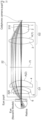
- Fig. 2 shows a Y-Z cross section through an implementation of a lens system of the first embodiment- here, configured as a rotationally-symmetrical dioptric afocal relay (telescope).
- a lens system of the first embodiment- here configured as a rotationally-symmetrical dioptric afocal relay (telescope).
- Telescope a rotationally-symmetrical dioptric afocal relay
- rays are traced from the cellphone camera EP on the right of Fig. 2 through the optical system in attachment 22, to a Navarro model eye on the left of Fig. 2 .
- the lens element closest to the cellphone camera pupil is labeled as element 1 in Fig. 2 ; the next lens element is element 2, and so on, while the retinal surface is referred to as an image plane.
- the design includes two cemented doublets (320 by the EP of the eye and 310 by the EP of the cellphone camera lens), while the single positive biconvex lens 3 has the highest converging power among the optical elements present in the embodiment.
- the cemented doublet lens 320 is composed of a positive meniscus lens element 6 concave to the eye side cemented with a meniscus lens element concave to the eye side.
- the first lens group G1 includes the cemented doublet lens 320 and a positive meniscus lens element 4 concave to the eye side.
- the cemented doublet lens 310 is composed of a biconcave negative lens element 1 cemented with a biconvex positive lens element 2.
- the second lens group G2 includes the cemented doublet lens 310 and a positive biconvex lens element 3.
- Fig. 2 The optical design of Fig. 2 is configured to compensate for the aberrations of the (Navarro model) eye (at 2 mm eye pupil diameter, the healthy human eye is almost diffraction-limited) and provides close to diffraction-limited resolution across the entire 80 degree FOV.
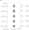
- Fig. 3 shows ray aberrations (spot diagrams) in the planes that are locally tangential to the spherical retina, at three identified wavelengths, 643.85 nm, 546.1 nm, and 479.99 nm.
- the proposed design of the optical system is such that diffraction-limited imaging of the retina is effectuated by balancing of optical aberrations typical for an average eye with those of the eye piece portion of the embodiment of the invention.
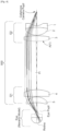
- Tables 1, 2, and 3 provide data representing an optical train (sequence) of lens elements of the first embodiment of Fig. 2
- Table 4 provide data representing an optical train (sequence) of lens elements of the second embodiment of Fig. 4 , forming lens systems configured according to the idea of the invention.
- the design prescriptions for the embodiments were generated with Code V and are discussed in reference to the corresponding Drawings.
- optical elements and, possibly, media separating some of the elements are numbered in a "backward" fashion, starting from that which is the closest to the object / target plane (illustrated in Fig. 4 ) towards the retinal surface of an eye.
- the NA and parameters characterizing the behavior of the system in the image space - that is, in the space of the eye - during the process of optical design.
- the closest lens element to the object is labeled as element 1 both in Table 4 and Fig. 4 ; the next lens element is element 2, and so on, while the retinal surface is referred to as an image plane.
- the combination with the Navarro model of the human eye is chosen, the typical optical properties and geometrical characteristics of which have to be included in the design of the relay system of the invention for proper assessment of the system.
- Positive radius value for a given surface indicates that the center of curvature of this surface is to the left of the surface, while a negative radius value indicates that the center of curvature is to the right of the surface; dimensions are provided in millimeters; thickness is defined as an axial distance from a given surface to the next surface; and an indicated image diameter is a paraxial value and not a ray-traced value.
- the second embodiment 500 of the relay system of the invention structured as described in the above Tables 4, 5 and 6 is presented in Fig. 4 and has an effective focal length of 30.67 mm (modulus value), which results in formation of an image with a (paraxial) height of about 10.6 mm, and is corrected well for lateral color aberration(s).
- the embodiment of the lens system according to the idea of the invention contains only one single aspheric surface A(1), which provides practical advantages (such as reduced costs).
- the second embodiment contains a first lens group G1 and a second lens group G2.
- the first lens group G1 includes lens elements 4 and 5
- the second lens group G2 includes lens elements 1, 2 and 3.
- the Navarro model of the eye is also shown in combination with the relay system 500.
- the second lens group G2 includes a first meniscus lens element 1 having a negative dioptric power and in optical contact with the biconvex positive lens element 2, and the element 3 having a positive optical power and an aspheric surface A(1) and spatially separated from the combination of the elements 1 and 2.
- the second lens group G2 aggregately possesses positive optical power, overriding the negative optical power of the element 1.
- the first lens group G1 contains a positive lens element 4 and a second meniscus lens element 5 concave to the eye side, and has aggregately possesses positive optical power.
- the first lens group G1 is positioned close to the eye to be inspected, as shown by the Navarro model of the eye in Fig 4 .
- Fig. 5 contains spot diagrams representing the effect of defocussing, while imaging an object with the second embodiment 500 of the invention, as a function of field position (expressed in degrees).
- the second embodiment is also shown to compensate for the aberrations of the (Navarro model) eye (at 2 mm eye pupil diameter, the healthy human eye is almost diffraction-limited) and provides close to diffraction-limited resolution across the entire 80 degree FOV
- aberrations are substantially corrected over the whole visible spectrum, but are even smaller at the red end of the spectrum (where the backscattered light from the retina is about five times stronger than that in the blue, which is operationally preferred during the imaging of the retina).
- the proposed design of the optical system is such that diffraction-limited imaging of the retina is effectuated by balancing of optical aberrations typical for an average eye with those of the eye piece portion of the embodiment of the invention.
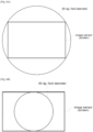
- magnification is chosen such that the 80 degree field of view entering the eye is imaged on to the camera screen (i.e., the size of the image sensor) to fill the short dimension of the rectangular screen, as shown in Fig. 6B .
- the camera screen i.e., the size of the image sensor
- This has the advantage that the whole 80 degree field of view is seen, but the disadvantage that not all of the camera pixels are used.
- This is the more common fundus camera situation but the two cases show that the invention can be applied to either situation by selecting the appropriate magnification close to 1.0, in the range 1.0 to 2.0.
- a specific implementation of the invention can also be structured to take advantage of fundus imaging with a dual-lens (or, generally, a multiple-lens) cellphone camera.
- a cellphone has a second camera lens with a different focal length (for example, twice the focal length of the first lens of the cellphone)
- a focal length for example, twice the focal length of the first lens of the cellphone
- the invention can optically (axially) align the second lens with the afocal relay-the central angular portion of the retina (the one corresponding to the cellphone lens having the smaller FOV as compared to the FOV of another lens of the cellphone) can be imaged at a higher resolution.
- image stitching could be used with the longer focal length lens, to cover an 80 degree field of view or more at higher resolution.
- the scope of the invention advantageously accommodates a situation in which a mobile device has multiple lenses (optical systems) disposed next to each other (as a 1D or 2D array of lenses, for example) and having different focal lengths (and, therefore, different FOVs) .
- the embodiment of Fig. 1 can be integrated with the back side of the mobile device through a contraption or positioner (driven mechanically or otherwise, for example, with the use of an electrical motor) configured to laterally reposition the embodiment in a plane perpendicular to the optical axes of such multiple lenses while maintaining the working (axial) distance between the embodiment and the plane in which the multiple lenses are disposed.
- the optical conjugation is established between the EP of the eye and the EP of the first lens and the 1x imaging of the retina with the use of the telescope of the invention and the first lens is advantageously enabled.
- the embodiment is translated to be co-axially disposed with a second lens of the cellphone camera, the optical conjugation is established between the EP of the eye and the EP of the second lens and the 1x imaging of the retina with the use of the telescope of the invention and the second lens is enabled.
- the user will not have their spectacles on when pictures are taken, so a +/- 10 Diopter adjustment can be provided by focusing the lenses closest to the eye- the eyepiece-based on the user's prescription.
- the camera's focusing system will adjust for fine focus.
- a low-cost eye fundus camera having a simple and small-sized configuration is enabled. Further, compared to a conventional eye fundus camera using an attachment lens, it is clear that a superior eye fundus image can be obtained across a field of view that is approximately twice as broad and across a broad wavelength region. Further, when a multiple-lens cellphone camera is used, the degree of freedom of the field of view and the resolution performance increases.
- attachment 22 is a relay optical system that relays the pupil of subject eye 150 to the pupil position of the optical system of image capture portion 214 of cellphone 20, and is provided with first positive lens group G1 and second positive lens group G2.
- First positive lens group G1 and second positive lens group G2 have the same optical axis and substantially form an afocal system.
- the pupil of subject eye 150 is relayed to the pupil of the optical system of image capture portion 214 of cellphone 20 by the combination of the first positive lens group G1 and the second positive lens group G2.
- the afocal relay of the invention goes on the front of the cellphone camera lens. In this case, it serves to relay the cellphone camera pupil to the iris (pupil) of the patient.
- the configuration is such that the eye side focal position of the first positive lens group G1 is aligned with the pupil position of subject eye 150, and such that the focal position, at the side of cellphone 20, of second positive lens group G2 is aligned with the pupil position of the image capture optical system of cellphone 20.
- the combination of the first positive lens group G1 and the second positive lens group G2 forms a conjugate relationship between the pupil of the subject eye and the pupil of the external optical system.
- the first positive lens group G1 includes, in the order from the side of the subject eye, positive meniscus lens 320, which has a concave surface facing the side of the subject eye, and positive lens 340
- the second positive lens group G2 includes, in the order from the side of the subject eye, positive lens 330 and meniscus lens 310, which has a convex surface facing the side of the subject eye.
- Positive meniscus lens 320 which has a concave surface facing the side of the subject eye, is not limited to the configuration shown in Fig. 7 , and may have the configuration shown in Fig. 2 , being a compound lens including positive meniscus lens 6, which has a concave surface facing the side of the subject eye, and meniscus lens 5, which has a concave surface facing the side of the subject eye.
- the meniscus lens 310 of the second positive lens group G2 which has a convex surface facing the side of the subject eye may, as shown in Fig. 7 , be a compound lens of biconvex positive lens 310A and biconcave positive lens 310B cemented with each other. Further, it is possible, as appropriate, to adopt an aspherical surface as the shape of the lens surface, and in the second example, an aspherical surface is provided at the convex surface, at the side of the subject eye, of the biconvex lens of the second lens group G2.
- f1 is the focal length of the first lens group G1
- f2 is the focal length of the second lens group G2
- D is the principal plane interval of both lens groups G1, G2, it is preferable that the following condition is substantially satisfied.
- f 1 + f 2 D
- first positive lens group G1 and second positive lens group G2 substantially form an afocal system, it is preferable that the following condition is satisfied. 0.9 ⁇ f 2 / f 1 ⁇ 2.2
- condition 1.0 ⁇ f2/f1 ⁇ 2.0 is preferably satisfied.
- the focal length f1 of the first lens group G1 and the focal length f2 of the second lens group G2 satisfy the following conditions. 30 mm ⁇ f 1 ⁇ 50 mm 30 mm ⁇ f 2 ⁇ 60 mm
- the angle of view of the second lens group G2 at the side of the optical system of cellphone 20 includes, and preferably matches, the angle of view of the optical system of cellphone 20.
- the image of the image capture field of view (FOV) of the subject eye fundus corresponding to the angle of view of the first lens group G1 is transferred to the optical system of cellphone 20 via second lens group G2.
- the 1x magnification of the relay optical system of attachment 22 of all the foregoing embodiments is the ideal for aberration correction; however, as mentioned above regarding the numerical conditions, a larger field of view than the cellphone camera is achieved by introducing a small amount of magnification, and the design is still able to achieve favorable aberration correction.
- a larger field of view is beneficial in that many pathologies of the retina can be seen within the 80 dg. field of view, and it is possible to switch to the cellphone telephoto lens camera to look in more detail at the central 40 dg. of the retina.
- attachment 22 is provided with a power source 380, a light source 362, which is supplied with power by the power source 380, and a beam splitter 372, which reflects light emitted from the light source 362 toward the side of second lens group G2 and passes light reflected from subject eye 150, via second lens group G2, through to cellphone 20.
- light emitted from the light source 362 is reflected, at the beam splitter 372, toward the side of second lens group G2 and arrives at the eye fundus of subject eye 150 via first lens group G1.
- Light that reached the eye fundus of subject eye 150 is reflected at the eye fundus, and the reflected light arrives at beam splitter 372 via the first lens group G1 and the second lens group G2, passes through the beam splitter 372, and arrives at the cellphone 20.
- the pupil of subject eye 150 is relayed to the pupil of the optical system of image capture portion 214 of the cellphone 20 by the first positive lens group G1 and the second positive lens group G2.
- the afocal attachment 22 has, in addition to the first lens group G1 and the second lens group G2, a light source 362 and a power source 380 for the light source 362. Divergent light from light source 362 is collimated by a condenser lens 364. Then, the collomated light is incident at diffuser 366 and becomes divergent light, and irradiates ring diaphragm 368, which has a ring-shaped aperture.
- the afocal attachment 22 includes contact 382, which is connected to light source 362.
- Cellphone 20 includes a contact 20C, which is connected to the battery (not shown) of the cellphone 20.
- the contact 382 of the attachment 22 and the contact 20C of the cellphone 20 are connected.
- the contact 382 is connected to the light source 362 and the contact 20C of the cellphone 20 is connected to the battery (not shown) of the cellphone 20, power from the battery (not shown) of the cellphone 20 is supplied to the light source 362 via the contact 20C and the contact 382.
- the cellphone 20 is provided with computer 200.
- Computer 200 is provided with CPU 202, ROM 204, RAM 206, and input and output (I/O) port 208.
- CPU 202, ROM 204, RAM 206, and I/O port 208 are mutually connected via bus 210.
- I/O port 208 is connected to auxiliary storage device 212, image capture portion 214, speaker 216, display portion 218, communication portion 220, home button 222, image capture button 224, and autofocus mechanism 226.
- Step 402 a user mounts attachment 22 at cellphone 20.
- an eye fundus image capture application starts up in Step 404.
- Step 406 the user holds their eye at the image capture position of image capture portion 214.
- Step 408 by turning on home button 222 of cellphone 20, CPU 202 initiates image capture mode.
- image capture portion 214 captures an eye fundus image via attachment 22.
- Step 410 CPU 202 adjusts autofocus mechanism 226, automatically adjusts the focus, and when the focus is automatically adjusted, determines whether or not the eye fundus image capture range of image capture portion 214 is appropriate.
- the position of the pupil of subject eye 150 is detected within the eye fundus image capture range of image capture portion 214 from the respective pixel values of the image data of the eye fundus image and from threshold values for distinguishing between a pupil portion and a peripheral portion. By determining whether or not the detected position of the pupil is within the image capture range, it is determined whether or not the image capture range is appropriate.
- CPU 202 When it is determined that the eye fundus image capture range is inappropriate in Step 410, CPU 202 emits an audio instruction to change the hold position of cellphone 20 via speaker 216 in Step 412. For example, when the pupil position is at a higher position than the image capture range of image capture portion 214, "please raise the cellphone” is audio output via speaker 216. Instead of the audio output of "please raise the cellphone", or together with this audio output, "please raise the cellphone” may be displayed at display portion 218.
- CPU 202 displays an image capture instruction at display portion 218 in Step 414.
- the user having seen the image capture instruction displayed at display portion 218, turns on image capture button 224.
- the image capture instruction is not limited to being displayed at display portion 218, and an image capture instruction may be audio output via speaker 216 instead of, or in addition to, this display.
- image capture button 224 is turned on, CPU 202 detects that image capture button 224 has been turned on in Step 416.
- the eye fundus image captured by image capture portion 214 is stored at auxiliary storage device 212 in Step 418, and, in Step 420, an image signal of the eye fundus image is transmitted to eye fundus image server 250 via communication portion 220.
- CPU 202 Omitting the processing of Steps 414 and 416 when it has been determined that the position of the user's eye fundus is appropriately positioned within the image capture range of image capture portion 214, CPU 202 stores the eye fundus image captured by image capture portion 214 at auxiliary storage device 212 in Step 418, and transmits an image signal of the eye fundus image to eye fundus image server 250 via communication portion 220 in Step 420.
- the cellphone 20 is provided with a single optical system (image capture lens system (camera lens)); however, the technique of the present disclosure is not limited thereto, and plural optical systems corresponding to plural angles of view may be provided.
- cellphone 20 may be provided with a first optical system for wide-angle use and a second optical system for standard use having a smaller angle of view than the wide angle.
- first mode that captures an image of the central portion and the peripheral portion of the eye fundus
- an image of the central portion and the peripheral portion of the eye fundus would be formed at image capture portion 214 via the first optical system.
- a second mode that only captures an image of the central portion an image of only the central portion of the eye fundus would be formed at image capture portion 214 via the second optical system.
Landscapes
- Health & Medical Sciences (AREA)
- Life Sciences & Earth Sciences (AREA)
- Physics & Mathematics (AREA)
- Engineering & Computer Science (AREA)
- Surgery (AREA)
- Public Health (AREA)
- Biomedical Technology (AREA)
- Heart & Thoracic Surgery (AREA)
- Medical Informatics (AREA)
- Molecular Biology (AREA)
- Biophysics (AREA)
- Animal Behavior & Ethology (AREA)
- General Health & Medical Sciences (AREA)
- Veterinary Medicine (AREA)
- Ophthalmology & Optometry (AREA)
- Multimedia (AREA)
- Pathology (AREA)
- General Physics & Mathematics (AREA)
- Optics & Photonics (AREA)
- Eye Examination Apparatus (AREA)
- Lenses (AREA)
Applications Claiming Priority (3)
| Application Number | Priority Date | Filing Date | Title |
|---|---|---|---|
| US201662381768P | 2016-08-31 | 2016-08-31 | |
| US201762539733P | 2017-08-01 | 2017-08-01 | |
| PCT/JP2017/031412 WO2018043657A1 (en) | 2016-08-31 | 2017-08-31 | Wide-angle pupil relay for cellphone-based fundus camera |
Publications (3)
| Publication Number | Publication Date |
|---|---|
| EP3506813A1 EP3506813A1 (en) | 2019-07-10 |
| EP3506813A4 EP3506813A4 (en) | 2020-04-29 |
| EP3506813B1 true EP3506813B1 (en) | 2024-03-13 |
Family
ID=61301090
Family Applications (1)
| Application Number | Title | Priority Date | Filing Date |
|---|---|---|---|
| EP17846661.1A Active EP3506813B1 (en) | 2016-08-31 | 2017-08-31 | Wide-angle pupil relay for cellphone-based fundus camera |
Country Status (5)
| Country | Link |
|---|---|
| US (2) | US11717161B2 (enExample) |
| EP (1) | EP3506813B1 (enExample) |
| JP (4) | JP2019526346A (enExample) |
| CN (2) | CN109640788A (enExample) |
| WO (1) | WO2018043657A1 (enExample) |
Families Citing this family (15)
| Publication number | Priority date | Publication date | Assignee | Title |
|---|---|---|---|---|
| JP2019526346A (ja) * | 2016-08-31 | 2019-09-19 | 株式会社ニコン | 携帯電話ベースの眼底カメラのための広角瞳孔リレー |
| US10595724B2 (en) * | 2017-08-04 | 2020-03-24 | Ho Wa LAI | Adaptor for an image capture device for fundus photography |
| US11147441B2 (en) | 2018-01-16 | 2021-10-19 | Welch Allyn, Inc. | Physical assessment device |
| CN116999015A (zh) | 2018-03-30 | 2023-11-07 | 株式会社尼康 | 眼科装置及眼科拍摄方法 |
| US20200193156A1 (en) | 2018-12-12 | 2020-06-18 | Tesseract Health, Inc. | Biometric identification techniques |
| WO2020251033A1 (en) | 2019-06-14 | 2020-12-17 | Nikon Corporation | Optical system for convertible imaging of posterior and anterior portions of the eye |
| US11737665B2 (en) | 2019-06-21 | 2023-08-29 | Tesseract Health, Inc. | Multi-modal eye imaging with shared optical path |
| KR102074429B1 (ko) * | 2019-08-23 | 2020-02-06 | 주식회사 디오스텍 | 광시야각을 가지며 경량화한 안저 카메라용 광학계 |
| WO2021060203A1 (ja) * | 2019-09-25 | 2021-04-01 | 株式会社ニコン | 眼科用光学系及び眼科装置 |
| WO2021065582A1 (ja) * | 2019-09-30 | 2021-04-08 | 株式会社ニコン | 眼科装置及び眼科用光学系 |
| KR102313856B1 (ko) * | 2020-04-01 | 2021-10-19 | 인더스마트 주식회사 | 안과용 광학 영상 시스템 및 이를 포함하는 광학 영상 촬영 장치 |
| CN111820864B (zh) * | 2020-07-31 | 2023-08-18 | 嘉兴中润光学科技股份有限公司 | 一种眼底成像系统 |
| EP4199801A1 (en) | 2020-08-19 | 2023-06-28 | Phelcom Technologies S/A | System, device and method for portable, connected and intelligent eye imaging |
| CN114271782A (zh) * | 2021-11-30 | 2022-04-05 | 视微影像(河南)科技有限公司 | 一种可切换成广角/超广角的眼底成像目镜 |
| PL443185A1 (pl) * | 2022-12-19 | 2024-06-24 | Solvemed Group Spółka Z Ograniczoną Odpowiedzialnością | Sposób i układ do bezwzględnego pomiaru średnicy fragmentu oka |
Citations (1)
| Publication number | Priority date | Publication date | Assignee | Title |
|---|---|---|---|---|
| US5061054A (en) * | 1988-03-15 | 1991-10-29 | Nikon Corporation | Keplerian finder optical system |
Family Cites Families (48)
| Publication number | Priority date | Publication date | Assignee | Title |
|---|---|---|---|---|
| DE2915639C2 (de) * | 1978-04-19 | 1988-06-16 | Canon K.K., Tokio/Tokyo | Augenuntersuchungsgerät zur Untersuchung des Augenhintergrundes |
| JPS5691729A (en) * | 1979-12-25 | 1981-07-24 | Nippon Chemical Ind | Optical system for examinating and photographing eyeground |
| JPS58150924A (ja) | 1982-03-04 | 1983-09-07 | Nippon Kogaku Kk <Nikon> | 二重共役維持光学系 |
| JPS60203233A (ja) * | 1984-03-28 | 1985-10-14 | 株式会社ニコン | 検眼装置の内焦光学系 |
| US5499066A (en) * | 1990-08-24 | 1996-03-12 | Remraf Pty. Ltd. | Optical instrument with a continuously adjustable zoom |
| JP3197418B2 (ja) * | 1993-04-24 | 2001-08-13 | 太陽誘電株式会社 | 光情報媒体 |
| JP3465997B2 (ja) * | 1995-04-28 | 2003-11-10 | 株式会社ニデック | 眼底カメラ |
| US20010041884A1 (en) * | 1996-11-25 | 2001-11-15 | Frey Rudolph W. | Method for determining and correcting vision |
| JP2000107134A (ja) | 1998-10-06 | 2000-04-18 | Canon Inc | 眼科撮影装置 |
| US20110286025A1 (en) * | 1999-12-01 | 2011-11-24 | Silverbrook Research Pty Ltd | Method of authenticating a print medium with plurality of coded data portions |
| US6550917B1 (en) * | 2000-02-11 | 2003-04-22 | Wavefront Sciences, Inc. | Dynamic range extension techniques for a wavefront sensor including use in ophthalmic measurement |
| US7025459B2 (en) * | 2000-07-14 | 2006-04-11 | Visual Pathways, Inc. | Ocular fundus auto imager |
| JP2002150274A (ja) | 2000-11-07 | 2002-05-24 | Masayuki Makita | 携帯無線端末及びそれを用いた認証方法 |
| JP2003019118A (ja) * | 2001-07-10 | 2003-01-21 | Canon Inc | 眼科用画像処理装置 |
| JP2003202626A (ja) * | 2001-12-28 | 2003-07-18 | Tochigi Nikon Corp | 撮影アダプタ |
| JP4094378B2 (ja) | 2002-08-26 | 2008-06-04 | 株式会社トプコン | 携帯型眼科装置及び眼科システム |
| JP4319009B2 (ja) * | 2003-11-14 | 2009-08-26 | 興和株式会社 | 眼科撮影装置 |
| US7347553B2 (en) * | 2004-09-24 | 2008-03-25 | Canon Kabushiki Kaisha | Ophthalmic image sensing apparatus |
| JP4769017B2 (ja) * | 2005-05-16 | 2011-09-07 | 興和株式会社 | 眼科撮影装置 |
| US7287854B2 (en) | 2004-09-27 | 2007-10-30 | Kowa Company Ltd. | Ophthalmic photography apparatus |
| US7850305B2 (en) * | 2004-12-03 | 2010-12-14 | Topcon Corporation | Apparatus and method for measuring spectrum image data of eyeground |
| DE102006036300B4 (de) * | 2005-08-26 | 2007-11-29 | Leica Microsystems (Schweiz) Ag | Hochleistungs-Stereomikroskop |
| US7830525B2 (en) | 2006-11-01 | 2010-11-09 | Bioptigen, Inc. | Optical coherence imaging systems having a mechanism for shifting focus and scanning modality and related adapters |
| JP2008197190A (ja) * | 2007-02-09 | 2008-08-28 | Olympus Corp | 顕微鏡撮影光学系 |
| US7854510B2 (en) * | 2008-10-16 | 2010-12-21 | Steven Roger Verdooner | Apparatus and method for imaging the eye |
| US8042945B2 (en) * | 2009-10-06 | 2011-10-25 | Hoya Corporation | Multifocal intraocular lens simulator and method of simulating multifocal intraocular lens |
| WO2011119602A2 (en) * | 2010-03-23 | 2011-09-29 | Steven Verdooner | Apparatus and method for imaging an eye |
| JP2012050621A (ja) * | 2010-08-31 | 2012-03-15 | Canon Inc | 撮影ユニット及びその制御方法 |
| WO2012177544A1 (en) * | 2011-06-18 | 2012-12-27 | Intuitive Medical Technologies, Llc | Smart-phone adapter for ophthalmoscope |
| JP2013085762A (ja) * | 2011-10-19 | 2013-05-13 | Canon Inc | 眼科装置、及び眼科撮影方法 |
| US20150021228A1 (en) | 2012-02-02 | 2015-01-22 | Visunex Medical Systems Co., Ltd. | Eye imaging apparatus and systems |
| JP5919100B2 (ja) * | 2012-06-04 | 2016-05-18 | 浜松ホトニクス株式会社 | 補償光学システムの調整方法および補償光学システム |
| JP3185211U (ja) | 2013-05-24 | 2013-08-08 | 弘一 関根 | アッタチメントレンズ |
| US20150045012A1 (en) * | 2013-08-08 | 2015-02-12 | Neuroptics, Inc. | Ophthalmic adapter for personal electronics |
| JP6077967B2 (ja) * | 2013-08-27 | 2017-02-08 | 富士フイルム株式会社 | 撮像装置 |
| JP5680164B2 (ja) | 2013-10-03 | 2015-03-04 | キヤノン株式会社 | 眼科装置、画像取得方法およびプログラム |
| WO2015054672A1 (en) | 2013-10-10 | 2015-04-16 | The Regents Of The University Of California | Ocular cellscope apparatus |
| US10078226B2 (en) | 2013-10-14 | 2018-09-18 | Welch Allyn, Inc. | Portable eye viewing device enabled for enhanced field of view |
| ITBS20130169A1 (it) * | 2013-11-15 | 2015-05-16 | Andrea Russo | Accessorio ottico per un dispositivo mobile |
| GB201400927D0 (en) * | 2014-01-20 | 2014-03-05 | Keeler Ltd | Ophthalmic apparatus |
| JP6080128B2 (ja) * | 2014-02-28 | 2017-02-15 | 株式会社トプコン | 眼科撮影装置およびこれに装着可能な光学ユニット |
| JP6450085B2 (ja) * | 2014-04-14 | 2019-01-09 | フェムトディプロイメンツ株式会社 | 健康状態検査装置 |
| CN107529983A (zh) | 2015-01-09 | 2018-01-02 | 智能视觉实验室股份有限公司 | 具有开放场对准通道的便携式波前像差仪 |
| WO2016127140A1 (en) | 2015-02-05 | 2016-08-11 | Duke University | Compact telescope configurations for light scanning systems and methods of using the same |
| JP3197418U (ja) * | 2015-02-25 | 2015-05-14 | 株式会社井澤 | 超近接撮影装置 |
| CN204542052U (zh) * | 2015-04-09 | 2015-08-12 | 重庆速魄光学仪器设计室 | 用于眼底成像的手机式结构装置 |
| JP2019526346A (ja) * | 2016-08-31 | 2019-09-19 | 株式会社ニコン | 携帯電話ベースの眼底カメラのための広角瞳孔リレー |
| JP2018068732A (ja) * | 2016-10-31 | 2018-05-10 | 株式会社トプコン | 眼科装置 |
-
2017
- 2017-08-31 JP JP2019511667A patent/JP2019526346A/ja active Pending
- 2017-08-31 CN CN201780053096.XA patent/CN109640788A/zh active Pending
- 2017-08-31 WO PCT/JP2017/031412 patent/WO2018043657A1/en not_active Ceased
- 2017-08-31 CN CN202211045538.5A patent/CN115363519B/zh active Active
- 2017-08-31 EP EP17846661.1A patent/EP3506813B1/en active Active
-
2019
- 2019-02-27 US US16/288,096 patent/US11717161B2/en active Active
-
2021
- 2021-12-07 JP JP2021198874A patent/JP2022037062A/ja active Pending
-
2023
- 2023-05-05 US US18/143,916 patent/US12156698B2/en active Active
- 2023-09-13 JP JP2023148826A patent/JP7736048B2/ja active Active
-
2025
- 2025-08-27 JP JP2025141529A patent/JP2025170376A/ja active Pending
Patent Citations (1)
| Publication number | Priority date | Publication date | Assignee | Title |
|---|---|---|---|---|
| US5061054A (en) * | 1988-03-15 | 1991-10-29 | Nikon Corporation | Keplerian finder optical system |
Also Published As
| Publication number | Publication date |
|---|---|
| JP7736048B2 (ja) | 2025-09-09 |
| JP2023169276A (ja) | 2023-11-29 |
| CN109640788A (zh) | 2019-04-16 |
| JP2019526346A (ja) | 2019-09-19 |
| WO2018043657A1 (en) | 2018-03-08 |
| EP3506813A1 (en) | 2019-07-10 |
| EP3506813A4 (en) | 2020-04-29 |
| US20230270328A1 (en) | 2023-08-31 |
| US20190261853A1 (en) | 2019-08-29 |
| CN115363519A (zh) | 2022-11-22 |
| US12156698B2 (en) | 2024-12-03 |
| CN115363519B (zh) | 2026-04-21 |
| JP2025170376A (ja) | 2025-11-18 |
| JP2022037062A (ja) | 2022-03-08 |
| US11717161B2 (en) | 2023-08-08 |
Similar Documents
| Publication | Publication Date | Title |
|---|---|---|
| US12156698B2 (en) | Wide-angle pupil relay for cellphone-based fundus camera | |
| US7448753B1 (en) | Portable Digital Medical Camera for Capturing Images of the Retina or the External Auditory Canal, and Methods of Use | |
| CN109381158B (zh) | 适配器、包含适配器的眼底照相系统及其使用方法 | |
| EP1694195B1 (en) | Digital documenting ophthalmoscope | |
| US6637882B1 (en) | Eye viewing device for retinal viewing through undilated pupil | |
| TWI813631B (zh) | 眼科光學系統、眼科裝置、及眼科系統 | |
| US20180344154A1 (en) | Wide angle stereoscopic funduscopy | |
| US20250339026A1 (en) | Optical system for convertible imaging of posterior and anterior portions of the eye | |
| CN110573059B (zh) | 眼科拍摄光学系统、眼科拍摄装置、眼科用图像获取方法及眼科用图像系统 | |
| JP6574434B2 (ja) | 視覚検査装置 | |
| JP2025083515A (ja) | 光学装置 | |
| JPWO2020115848A1 (ja) | 光学ユニット、光学装置、及び画像表示システム |
Legal Events
| Date | Code | Title | Description |
|---|---|---|---|
| STAA | Information on the status of an ep patent application or granted ep patent |
Free format text: STATUS: THE INTERNATIONAL PUBLICATION HAS BEEN MADE |
|
| PUAI | Public reference made under article 153(3) epc to a published international application that has entered the european phase |
Free format text: ORIGINAL CODE: 0009012 |
|
| STAA | Information on the status of an ep patent application or granted ep patent |
Free format text: STATUS: REQUEST FOR EXAMINATION WAS MADE |
|
| 17P | Request for examination filed |
Effective date: 20190228 |
|
| AK | Designated contracting states |
Kind code of ref document: A1 Designated state(s): AL AT BE BG CH CY CZ DE DK EE ES FI FR GB GR HR HU IE IS IT LI LT LU LV MC MK MT NL NO PL PT RO RS SE SI SK SM TR |
|
| AX | Request for extension of the european patent |
Extension state: BA ME |
|
| DAV | Request for validation of the european patent (deleted) | ||
| DAX | Request for extension of the european patent (deleted) | ||
| A4 | Supplementary search report drawn up and despatched |
Effective date: 20200327 |
|
| RIC1 | Information provided on ipc code assigned before grant |
Ipc: A61B 3/12 20060101ALI20200324BHEP Ipc: A61B 3/14 20060101AFI20200324BHEP |
|
| STAA | Information on the status of an ep patent application or granted ep patent |
Free format text: STATUS: EXAMINATION IS IN PROGRESS |
|
| 17Q | First examination report despatched |
Effective date: 20220512 |
|
| P01 | Opt-out of the competence of the unified patent court (upc) registered |
Effective date: 20230517 |
|
| GRAP | Despatch of communication of intention to grant a patent |
Free format text: ORIGINAL CODE: EPIDOSNIGR1 |
|
| STAA | Information on the status of an ep patent application or granted ep patent |
Free format text: STATUS: GRANT OF PATENT IS INTENDED |
|
| INTG | Intention to grant announced |
Effective date: 20230922 |
|
| GRAS | Grant fee paid |
Free format text: ORIGINAL CODE: EPIDOSNIGR3 |
|
| GRAA | (expected) grant |
Free format text: ORIGINAL CODE: 0009210 |
|
| STAA | Information on the status of an ep patent application or granted ep patent |
Free format text: STATUS: THE PATENT HAS BEEN GRANTED |
|
| AK | Designated contracting states |
Kind code of ref document: B1 Designated state(s): AL AT BE BG CH CY CZ DE DK EE ES FI FR GB GR HR HU IE IS IT LI LT LU LV MC MK MT NL NO PL PT RO RS SE SI SK SM TR |
|
| REG | Reference to a national code |
Ref country code: GB Ref legal event code: FG4D |
|
| REG | Reference to a national code |
Ref country code: CH Ref legal event code: EP |
|
| REG | Reference to a national code |
Ref country code: DE Ref legal event code: R096 Ref document number: 602017080067 Country of ref document: DE |
|
| REG | Reference to a national code |
Ref country code: IE Ref legal event code: FG4D |
|
| PG25 | Lapsed in a contracting state [announced via postgrant information from national office to epo] |
Ref country code: LT Free format text: LAPSE BECAUSE OF FAILURE TO SUBMIT A TRANSLATION OF THE DESCRIPTION OR TO PAY THE FEE WITHIN THE PRESCRIBED TIME-LIMIT Effective date: 20240313 |
|
| REG | Reference to a national code |
Ref country code: LT Ref legal event code: MG9D |
|
| PG25 | Lapsed in a contracting state [announced via postgrant information from national office to epo] |
Ref country code: GR Free format text: LAPSE BECAUSE OF FAILURE TO SUBMIT A TRANSLATION OF THE DESCRIPTION OR TO PAY THE FEE WITHIN THE PRESCRIBED TIME-LIMIT Effective date: 20240614 |
|
| REG | Reference to a national code |
Ref country code: NL Ref legal event code: MP Effective date: 20240313 |
|
| PG25 | Lapsed in a contracting state [announced via postgrant information from national office to epo] |
Ref country code: HR Free format text: LAPSE BECAUSE OF FAILURE TO SUBMIT A TRANSLATION OF THE DESCRIPTION OR TO PAY THE FEE WITHIN THE PRESCRIBED TIME-LIMIT Effective date: 20240313 Ref country code: RS Free format text: LAPSE BECAUSE OF FAILURE TO SUBMIT A TRANSLATION OF THE DESCRIPTION OR TO PAY THE FEE WITHIN THE PRESCRIBED TIME-LIMIT Effective date: 20240613 |
|
| PG25 | Lapsed in a contracting state [announced via postgrant information from national office to epo] |
Ref country code: ES Free format text: LAPSE BECAUSE OF FAILURE TO SUBMIT A TRANSLATION OF THE DESCRIPTION OR TO PAY THE FEE WITHIN THE PRESCRIBED TIME-LIMIT Effective date: 20240313 |
|
| PG25 | Lapsed in a contracting state [announced via postgrant information from national office to epo] |
Ref country code: RS Free format text: LAPSE BECAUSE OF FAILURE TO SUBMIT A TRANSLATION OF THE DESCRIPTION OR TO PAY THE FEE WITHIN THE PRESCRIBED TIME-LIMIT Effective date: 20240613 Ref country code: NO Free format text: LAPSE BECAUSE OF FAILURE TO SUBMIT A TRANSLATION OF THE DESCRIPTION OR TO PAY THE FEE WITHIN THE PRESCRIBED TIME-LIMIT Effective date: 20240613 Ref country code: LT Free format text: LAPSE BECAUSE OF FAILURE TO SUBMIT A TRANSLATION OF THE DESCRIPTION OR TO PAY THE FEE WITHIN THE PRESCRIBED TIME-LIMIT Effective date: 20240313 Ref country code: HR Free format text: LAPSE BECAUSE OF FAILURE TO SUBMIT A TRANSLATION OF THE DESCRIPTION OR TO PAY THE FEE WITHIN THE PRESCRIBED TIME-LIMIT Effective date: 20240313 Ref country code: GR Free format text: LAPSE BECAUSE OF FAILURE TO SUBMIT A TRANSLATION OF THE DESCRIPTION OR TO PAY THE FEE WITHIN THE PRESCRIBED TIME-LIMIT Effective date: 20240614 Ref country code: FI Free format text: LAPSE BECAUSE OF FAILURE TO SUBMIT A TRANSLATION OF THE DESCRIPTION OR TO PAY THE FEE WITHIN THE PRESCRIBED TIME-LIMIT Effective date: 20240313 Ref country code: ES Free format text: LAPSE BECAUSE OF FAILURE TO SUBMIT A TRANSLATION OF THE DESCRIPTION OR TO PAY THE FEE WITHIN THE PRESCRIBED TIME-LIMIT Effective date: 20240313 Ref country code: BG Free format text: LAPSE BECAUSE OF FAILURE TO SUBMIT A TRANSLATION OF THE DESCRIPTION OR TO PAY THE FEE WITHIN THE PRESCRIBED TIME-LIMIT Effective date: 20240313 |
|
| REG | Reference to a national code |
Ref country code: AT Ref legal event code: MK05 Ref document number: 1664936 Country of ref document: AT Kind code of ref document: T Effective date: 20240313 |
|
| PG25 | Lapsed in a contracting state [announced via postgrant information from national office to epo] |
Ref country code: SE Free format text: LAPSE BECAUSE OF FAILURE TO SUBMIT A TRANSLATION OF THE DESCRIPTION OR TO PAY THE FEE WITHIN THE PRESCRIBED TIME-LIMIT Effective date: 20240313 Ref country code: LV Free format text: LAPSE BECAUSE OF FAILURE TO SUBMIT A TRANSLATION OF THE DESCRIPTION OR TO PAY THE FEE WITHIN THE PRESCRIBED TIME-LIMIT Effective date: 20240313 |
|
| PG25 | Lapsed in a contracting state [announced via postgrant information from national office to epo] |
Ref country code: NL Free format text: LAPSE BECAUSE OF FAILURE TO SUBMIT A TRANSLATION OF THE DESCRIPTION OR TO PAY THE FEE WITHIN THE PRESCRIBED TIME-LIMIT Effective date: 20240313 |
|
| PG25 | Lapsed in a contracting state [announced via postgrant information from national office to epo] |
Ref country code: NL Free format text: LAPSE BECAUSE OF FAILURE TO SUBMIT A TRANSLATION OF THE DESCRIPTION OR TO PAY THE FEE WITHIN THE PRESCRIBED TIME-LIMIT Effective date: 20240313 |
|
| PG25 | Lapsed in a contracting state [announced via postgrant information from national office to epo] |
Ref country code: IS Free format text: LAPSE BECAUSE OF FAILURE TO SUBMIT A TRANSLATION OF THE DESCRIPTION OR TO PAY THE FEE WITHIN THE PRESCRIBED TIME-LIMIT Effective date: 20240713 |
|
| PG25 | Lapsed in a contracting state [announced via postgrant information from national office to epo] |
Ref country code: PT Free format text: LAPSE BECAUSE OF FAILURE TO SUBMIT A TRANSLATION OF THE DESCRIPTION OR TO PAY THE FEE WITHIN THE PRESCRIBED TIME-LIMIT Effective date: 20240715 Ref country code: SM Free format text: LAPSE BECAUSE OF FAILURE TO SUBMIT A TRANSLATION OF THE DESCRIPTION OR TO PAY THE FEE WITHIN THE PRESCRIBED TIME-LIMIT Effective date: 20240313 |
|
| PG25 | Lapsed in a contracting state [announced via postgrant information from national office to epo] |
Ref country code: EE Free format text: LAPSE BECAUSE OF FAILURE TO SUBMIT A TRANSLATION OF THE DESCRIPTION OR TO PAY THE FEE WITHIN THE PRESCRIBED TIME-LIMIT Effective date: 20240313 Ref country code: CZ Free format text: LAPSE BECAUSE OF FAILURE TO SUBMIT A TRANSLATION OF THE DESCRIPTION OR TO PAY THE FEE WITHIN THE PRESCRIBED TIME-LIMIT Effective date: 20240313 |
|
| PG25 | Lapsed in a contracting state [announced via postgrant information from national office to epo] |
Ref country code: AT Free format text: LAPSE BECAUSE OF FAILURE TO SUBMIT A TRANSLATION OF THE DESCRIPTION OR TO PAY THE FEE WITHIN THE PRESCRIBED TIME-LIMIT Effective date: 20240313 |
|
| PG25 | Lapsed in a contracting state [announced via postgrant information from national office to epo] |
Ref country code: PL Free format text: LAPSE BECAUSE OF FAILURE TO SUBMIT A TRANSLATION OF THE DESCRIPTION OR TO PAY THE FEE WITHIN THE PRESCRIBED TIME-LIMIT Effective date: 20240313 |
|
| PG25 | Lapsed in a contracting state [announced via postgrant information from national office to epo] |
Ref country code: SK Free format text: LAPSE BECAUSE OF FAILURE TO SUBMIT A TRANSLATION OF THE DESCRIPTION OR TO PAY THE FEE WITHIN THE PRESCRIBED TIME-LIMIT Effective date: 20240313 |
|
| PG25 | Lapsed in a contracting state [announced via postgrant information from national office to epo] |
Ref country code: SM Free format text: LAPSE BECAUSE OF FAILURE TO SUBMIT A TRANSLATION OF THE DESCRIPTION OR TO PAY THE FEE WITHIN THE PRESCRIBED TIME-LIMIT Effective date: 20240313 Ref country code: SK Free format text: LAPSE BECAUSE OF FAILURE TO SUBMIT A TRANSLATION OF THE DESCRIPTION OR TO PAY THE FEE WITHIN THE PRESCRIBED TIME-LIMIT Effective date: 20240313 Ref country code: RO Free format text: LAPSE BECAUSE OF FAILURE TO SUBMIT A TRANSLATION OF THE DESCRIPTION OR TO PAY THE FEE WITHIN THE PRESCRIBED TIME-LIMIT Effective date: 20240313 Ref country code: PT Free format text: LAPSE BECAUSE OF FAILURE TO SUBMIT A TRANSLATION OF THE DESCRIPTION OR TO PAY THE FEE WITHIN THE PRESCRIBED TIME-LIMIT Effective date: 20240715 Ref country code: PL Free format text: LAPSE BECAUSE OF FAILURE TO SUBMIT A TRANSLATION OF THE DESCRIPTION OR TO PAY THE FEE WITHIN THE PRESCRIBED TIME-LIMIT Effective date: 20240313 Ref country code: IS Free format text: LAPSE BECAUSE OF FAILURE TO SUBMIT A TRANSLATION OF THE DESCRIPTION OR TO PAY THE FEE WITHIN THE PRESCRIBED TIME-LIMIT Effective date: 20240713 Ref country code: EE Free format text: LAPSE BECAUSE OF FAILURE TO SUBMIT A TRANSLATION OF THE DESCRIPTION OR TO PAY THE FEE WITHIN THE PRESCRIBED TIME-LIMIT Effective date: 20240313 Ref country code: CZ Free format text: LAPSE BECAUSE OF FAILURE TO SUBMIT A TRANSLATION OF THE DESCRIPTION OR TO PAY THE FEE WITHIN THE PRESCRIBED TIME-LIMIT Effective date: 20240313 Ref country code: AT Free format text: LAPSE BECAUSE OF FAILURE TO SUBMIT A TRANSLATION OF THE DESCRIPTION OR TO PAY THE FEE WITHIN THE PRESCRIBED TIME-LIMIT Effective date: 20240313 |
|
| PG25 | Lapsed in a contracting state [announced via postgrant information from national office to epo] |
Ref country code: IT Free format text: LAPSE BECAUSE OF FAILURE TO SUBMIT A TRANSLATION OF THE DESCRIPTION OR TO PAY THE FEE WITHIN THE PRESCRIBED TIME-LIMIT Effective date: 20240313 |
|
| REG | Reference to a national code |
Ref country code: DE Ref legal event code: R097 Ref document number: 602017080067 Country of ref document: DE |
|
| PG25 | Lapsed in a contracting state [announced via postgrant information from national office to epo] |
Ref country code: IT Free format text: LAPSE BECAUSE OF FAILURE TO SUBMIT A TRANSLATION OF THE DESCRIPTION OR TO PAY THE FEE WITHIN THE PRESCRIBED TIME-LIMIT Effective date: 20240313 |
|
| PG25 | Lapsed in a contracting state [announced via postgrant information from national office to epo] |
Ref country code: DK Free format text: LAPSE BECAUSE OF FAILURE TO SUBMIT A TRANSLATION OF THE DESCRIPTION OR TO PAY THE FEE WITHIN THE PRESCRIBED TIME-LIMIT Effective date: 20240313 |
|
| PLBE | No opposition filed within time limit |
Free format text: ORIGINAL CODE: 0009261 |
|
| STAA | Information on the status of an ep patent application or granted ep patent |
Free format text: STATUS: NO OPPOSITION FILED WITHIN TIME LIMIT |
|
| PG25 | Lapsed in a contracting state [announced via postgrant information from national office to epo] |
Ref country code: DK Free format text: LAPSE BECAUSE OF FAILURE TO SUBMIT A TRANSLATION OF THE DESCRIPTION OR TO PAY THE FEE WITHIN THE PRESCRIBED TIME-LIMIT Effective date: 20240313 |
|
| 26N | No opposition filed |
Effective date: 20241216 |
|
| REG | Reference to a national code |
Ref country code: CH Ref legal event code: PL |
|
| PG25 | Lapsed in a contracting state [announced via postgrant information from national office to epo] |
Ref country code: LU Free format text: LAPSE BECAUSE OF NON-PAYMENT OF DUE FEES Effective date: 20240831 |
|
| PG25 | Lapsed in a contracting state [announced via postgrant information from national office to epo] |
Ref country code: SI Free format text: LAPSE BECAUSE OF FAILURE TO SUBMIT A TRANSLATION OF THE DESCRIPTION OR TO PAY THE FEE WITHIN THE PRESCRIBED TIME-LIMIT Effective date: 20240313 Ref country code: CH Free format text: LAPSE BECAUSE OF NON-PAYMENT OF DUE FEES Effective date: 20240831 Ref country code: MC Free format text: LAPSE BECAUSE OF FAILURE TO SUBMIT A TRANSLATION OF THE DESCRIPTION OR TO PAY THE FEE WITHIN THE PRESCRIBED TIME-LIMIT Effective date: 20240313 |
|
| REG | Reference to a national code |
Ref country code: BE Ref legal event code: MM Effective date: 20240831 |
|
| PG25 | Lapsed in a contracting state [announced via postgrant information from national office to epo] |
Ref country code: BE Free format text: LAPSE BECAUSE OF NON-PAYMENT OF DUE FEES Effective date: 20240831 |
|
| PG25 | Lapsed in a contracting state [announced via postgrant information from national office to epo] |
Ref country code: FR Free format text: LAPSE BECAUSE OF NON-PAYMENT OF DUE FEES Effective date: 20240831 |
|
| PG25 | Lapsed in a contracting state [announced via postgrant information from national office to epo] |
Ref country code: IE Free format text: LAPSE BECAUSE OF NON-PAYMENT OF DUE FEES Effective date: 20240831 |
|
| PGFP | Annual fee paid to national office [announced via postgrant information from national office to epo] |
Ref country code: DE Payment date: 20250702 Year of fee payment: 9 |
|
| PGFP | Annual fee paid to national office [announced via postgrant information from national office to epo] |
Ref country code: GB Payment date: 20250703 Year of fee payment: 9 |
|
| PG25 | Lapsed in a contracting state [announced via postgrant information from national office to epo] |
Ref country code: CY Free format text: LAPSE BECAUSE OF FAILURE TO SUBMIT A TRANSLATION OF THE DESCRIPTION OR TO PAY THE FEE WITHIN THE PRESCRIBED TIME-LIMIT; INVALID AB INITIO Effective date: 20170831 |
|
| PG25 | Lapsed in a contracting state [announced via postgrant information from national office to epo] |
Ref country code: HU Free format text: LAPSE BECAUSE OF FAILURE TO SUBMIT A TRANSLATION OF THE DESCRIPTION OR TO PAY THE FEE WITHIN THE PRESCRIBED TIME-LIMIT; INVALID AB INITIO Effective date: 20170831 |