EP3504433B2 - Motor-pumpenvorrichtung - Google Patents
Motor-pumpenvorrichtung Download PDFInfo
- Publication number
- EP3504433B2 EP3504433B2 EP17761804.8A EP17761804A EP3504433B2 EP 3504433 B2 EP3504433 B2 EP 3504433B2 EP 17761804 A EP17761804 A EP 17761804A EP 3504433 B2 EP3504433 B2 EP 3504433B2
- Authority
- EP
- European Patent Office
- Prior art keywords
- pump
- motor
- housing
- electric motor
- supply
- Prior art date
- Legal status (The legal status is an assumption and is not a legal conclusion. Google has not performed a legal analysis and makes no representation as to the accuracy of the status listed.)
- Active
Links
Images
Classifications
-
- F—MECHANICAL ENGINEERING; LIGHTING; HEATING; WEAPONS; BLASTING
- F04—POSITIVE - DISPLACEMENT MACHINES FOR LIQUIDS; PUMPS FOR LIQUIDS OR ELASTIC FLUIDS
- F04B—POSITIVE-DISPLACEMENT MACHINES FOR LIQUIDS; PUMPS
- F04B23/00—Pumping installations or systems
- F04B23/04—Combinations of two or more pumps
- F04B23/08—Combinations of two or more pumps the pumps being of different types
- F04B23/10—Combinations of two or more pumps the pumps being of different types at least one pump being of the reciprocating positive-displacement type
- F04B23/103—Combinations of two or more pumps the pumps being of different types at least one pump being of the reciprocating positive-displacement type being a radial piston pump
-
- F—MECHANICAL ENGINEERING; LIGHTING; HEATING; WEAPONS; BLASTING
- F01—MACHINES OR ENGINES IN GENERAL; ENGINE PLANTS IN GENERAL; STEAM ENGINES
- F01C—ROTARY-PISTON OR OSCILLATING-PISTON MACHINES OR ENGINES
- F01C21/00—Component parts, details or accessories not provided for in groups F01C1/00 - F01C20/00
- F01C21/007—General arrangements of parts; Frames and supporting elements
-
- F—MECHANICAL ENGINEERING; LIGHTING; HEATING; WEAPONS; BLASTING
- F04—POSITIVE - DISPLACEMENT MACHINES FOR LIQUIDS; PUMPS FOR LIQUIDS OR ELASTIC FLUIDS
- F04B—POSITIVE-DISPLACEMENT MACHINES FOR LIQUIDS; PUMPS
- F04B17/00—Pumps characterised by combination with, or adaptation to, specific driving engines or motors
- F04B17/03—Pumps characterised by combination with, or adaptation to, specific driving engines or motors driven by electric motors
-
- F—MECHANICAL ENGINEERING; LIGHTING; HEATING; WEAPONS; BLASTING
- F04—POSITIVE - DISPLACEMENT MACHINES FOR LIQUIDS; PUMPS FOR LIQUIDS OR ELASTIC FLUIDS
- F04B—POSITIVE-DISPLACEMENT MACHINES FOR LIQUIDS; PUMPS
- F04B23/00—Pumping installations or systems
- F04B23/02—Pumping installations or systems having reservoirs
- F04B23/025—Pumping installations or systems having reservoirs the pump being located directly adjacent the reservoir
- F04B23/026—Pumping installations or systems having reservoirs the pump being located directly adjacent the reservoir a pump-side forming a wall of the reservoir
-
- F—MECHANICAL ENGINEERING; LIGHTING; HEATING; WEAPONS; BLASTING
- F04—POSITIVE - DISPLACEMENT MACHINES FOR LIQUIDS; PUMPS FOR LIQUIDS OR ELASTIC FLUIDS
- F04B—POSITIVE-DISPLACEMENT MACHINES FOR LIQUIDS; PUMPS
- F04B23/00—Pumping installations or systems
- F04B23/04—Combinations of two or more pumps
- F04B23/08—Combinations of two or more pumps the pumps being of different types
- F04B23/12—Combinations of two or more pumps the pumps being of different types at least one pump being of the rotary-piston positive-displacement type
-
- F—MECHANICAL ENGINEERING; LIGHTING; HEATING; WEAPONS; BLASTING
- F04—POSITIVE - DISPLACEMENT MACHINES FOR LIQUIDS; PUMPS FOR LIQUIDS OR ELASTIC FLUIDS
- F04C—ROTARY-PISTON, OR OSCILLATING-PISTON, POSITIVE-DISPLACEMENT MACHINES FOR LIQUIDS; ROTARY-PISTON, OR OSCILLATING-PISTON, POSITIVE-DISPLACEMENT PUMPS
- F04C11/00—Combinations of two or more machines or pumps, each being of rotary-piston or oscillating-piston type; Pumping installations
- F04C11/005—Combinations of two or more machines or pumps, each being of rotary-piston or oscillating-piston type; Pumping installations of dissimilar working principle
-
- F—MECHANICAL ENGINEERING; LIGHTING; HEATING; WEAPONS; BLASTING
- F04—POSITIVE - DISPLACEMENT MACHINES FOR LIQUIDS; PUMPS FOR LIQUIDS OR ELASTIC FLUIDS
- F04C—ROTARY-PISTON, OR OSCILLATING-PISTON, POSITIVE-DISPLACEMENT MACHINES FOR LIQUIDS; ROTARY-PISTON, OR OSCILLATING-PISTON, POSITIVE-DISPLACEMENT PUMPS
- F04C2/00—Rotary-piston machines or pumps
- F04C2/08—Rotary-piston machines or pumps of intermeshing-engagement type, i.e. with engagement of co-operating members similar to that of toothed gearing
- F04C2/10—Rotary-piston machines or pumps of intermeshing-engagement type, i.e. with engagement of co-operating members similar to that of toothed gearing of internal-axis type with the outer member having more teeth or tooth-equivalents, e.g. rollers, than the inner member
-
- F—MECHANICAL ENGINEERING; LIGHTING; HEATING; WEAPONS; BLASTING
- F04—POSITIVE - DISPLACEMENT MACHINES FOR LIQUIDS; PUMPS FOR LIQUIDS OR ELASTIC FLUIDS
- F04C—ROTARY-PISTON, OR OSCILLATING-PISTON, POSITIVE-DISPLACEMENT MACHINES FOR LIQUIDS; ROTARY-PISTON, OR OSCILLATING-PISTON, POSITIVE-DISPLACEMENT PUMPS
- F04C2/00—Rotary-piston machines or pumps
- F04C2/08—Rotary-piston machines or pumps of intermeshing-engagement type, i.e. with engagement of co-operating members similar to that of toothed gearing
- F04C2/12—Rotary-piston machines or pumps of intermeshing-engagement type, i.e. with engagement of co-operating members similar to that of toothed gearing of other than internal-axis type
- F04C2/14—Rotary-piston machines or pumps of intermeshing-engagement type, i.e. with engagement of co-operating members similar to that of toothed gearing of other than internal-axis type with toothed rotary pistons
-
- F—MECHANICAL ENGINEERING; LIGHTING; HEATING; WEAPONS; BLASTING
- F04—POSITIVE - DISPLACEMENT MACHINES FOR LIQUIDS; PUMPS FOR LIQUIDS OR ELASTIC FLUIDS
- F04C—ROTARY-PISTON, OR OSCILLATING-PISTON, POSITIVE-DISPLACEMENT MACHINES FOR LIQUIDS; ROTARY-PISTON, OR OSCILLATING-PISTON, POSITIVE-DISPLACEMENT PUMPS
- F04C2240/00—Components
- F04C2240/70—Use of multiplicity of similar components; Modular construction
Definitions
- the invention relates to a motor-pump device with the features in the preamble of claim 1.
- Such devices are also known in technical terms as motor-pump units and are primarily used to supply hydraulic circuits with hydraulic oil at a predetermined pressure.
- the units mentioned are generally characterized by a high power density with small dimensions and can be provided as a functional structural unit for the aforementioned pressure oil supply to oil-hydraulic systems.
- Such a hydraulic compact unit is exemplary in the DE 196 52 706 A1 shown, which has a ring-cylindrical pressure medium container as a tank unit, which has an outer outer wall and an inner outer wall as well as two front flanges, with a closed electric motor surrounded by the pressure medium container and cooled by a cooling air flow and with a hydraulic pump that can be driven by the electric motor as a supply pump for the respective hydraulic circulation.
- the aim here is for such a unit to have a very compact structure with sufficient cooling of the electric motor for continuous operation, especially in the form of an attachment.
- the pressure medium container closely surrounds the electric motor and the inner outer wall of the pressure medium container, provided with cooling fins, serves as a guide for the cooling air flow passing over the electric motor. In this way, all of the air flowing between the electric motor and the pressure medium container is fully used to cool the electric motor and also passes closely along the winding heads of the electric motor, which are remote from a fan wheel, along the housing of the electric motor.
- the DE 299 06 881 U1 discloses a motor-pump device with the features in the preamble of claim 1, designed as a modular system, consisting of at least one electric motor, a rotor of the electric motor being connected to a drive shaft thereof, which is rotatably mounted at the ends in bearing points, and between the end bearing points there is also a further third bearing point, which is accommodated on an inner wall in a multi-part motor housing of the electric motor, a radial piston pump which can be driven by the electric motor and which preferably serves a high-pressure supply, and/or a gear pump which preferably serves a low-pressure supply, a tank unit, and attachments, such as valves in longitudinal linkage and level meters, whereby to implement a hydraulic single or multi-circuit system, each supply pump used has its own supply connection for the respective circuit of the system used, or several supply pumps used feed into a common supply connection, or a single supply pump, which is preferably used for high-pressure delivery, has several supply lines, each of which is connected
- the EP 2 241 753 A1 and the EP 2 025 934 A1 disclose further motor pump devices.
- the invention is based on the object of further improving the above-mentioned units in such a way that, despite their compact design and high specific performance, they are designed to be thermally advantageous in such a way that they can operate in uninterrupted periodic operation (S6) up to can be used casually for continuous operation (S1).
- a motor-pump device that is designed as a modular system solves this problem in accordance with the feature design of patent claim 1.
- the housing of the tank unit designed as an extruded profile, has axially continuous cooling fins along its outer circumference facing the environment, which are an integral part of the extruded profile, that the housing of the tank unit is designed as a cylindrical body and that A flange plate is arranged along its outer circumference, which merges integrally into the cylindrical body and that this flange plate allows the installation of the motor-pump device in a horizontal installation position and a tank foot allows the vertical installation position.
- a motor-pump device can be constructed to obtain a variety of pressure combinations in practice.
- the above-mentioned use of different supply pumps, pump sizes, motors, installation positions, tank lengths, etc. results in a very high variety of variants, which, depending on the application for the unit, can be designed from a thermal point of view in such a way that uninterrupted periodic operation (S6) up to for continuous operation (S1) is possible.
- the exact duty cycle must be selected depending on the output power of the unit as well as the operating and environmental conditions in such a way that a maximum permissible operating temperature, for example in the form of the oil temperature in the unit, preferably 80 ° C, is not exceeded.
- a temperature switch can preferably be used inside or outside the unit.
- the special features of the motor-pump device are based on the flexible modular system according to the invention according to the feature design of patent claim 1, which, among other things, includes the combination of high and / or low pressure with only an aggregate enables. In this way, the implementation of so-called one- to two-circuit supply systems is also possible.
- the unit according to the invention can be used both horizontally and vertically and the tank unit in the form of the oil container can be flexibly adjusted to the oil volume required in each case.
- the housing of its tank unit designed as an extruded profile
- the ribbed tank outer profile mentioned preferably made of aluminum material
- the desired increased operating mode can be achieved in this way.
- additional cooling measures can be avoided, such as attaching a fan, the fan wheel of which is to be driven via a drive shaft by the electric motor next to the respective supply pump, which leads to corresponding losses in the operation of the known aggregates.
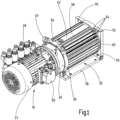
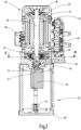
- the ones in the Fig. 2 The motor-pump device shown is designed as a modular system and has an electric motor designated as a whole by 10.
- the electric motor 10 can consist of a conventional asynchronous machine with an external stator 12 and an internal rotor 14 (see Fig. 2 ).
- the rotor 14 is connected in the usual way to a drive shaft 16 of the electric motor 10, which is rotatably mounted in bearing points 18 at the ends. Between the end bearing points 18 there is another third bearing point 20, which is accommodated on an inner wall in the multi-part motor housing 22 of the electric motor 10.
- the electric motor 10 can be equipped with or without a fan wheel; here in Fig. 1 and 2 shown with fan wheel.
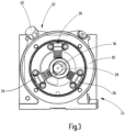
- a radial piston pump 24 is installed below the motor housing 22 with a total of three pump elements 26 as shown in the illustration Fig. 3 .
- three pistons or pump elements 26 six pistons or pump elements can also be used for the radial piston pump.
- the mentioned three or six valve spring-controlled radial piston pump elements 26 are actuated independently of the direction of rotation by an eccentric drive 28, which is driven by the external electric motor 10, namely via its drive shaft 16.
- Pump elements 26 shown are accommodated in a pump housing in the manner of an annular flange 30.
- This ring flange 30 is, like this in particular Fig. 2 shows, recorded between the electric motor 10 and a tank unit of the motor-pump device, designated as a whole by 32.
- the interior of the tank unit 32 serves to hold a predeterminable amount of oil fluid.
- a gear pump 34 is integrated within the tank unit 32, the technical structure of which is common and is therefore no longer shown in more detail. The gear pump 34 can be seen in the direction of view Fig.
- the radial piston pump 24 also has a suction line 38 with a filter element 39 for the purpose of filtering the oil removed from the tank 32 by means of the radial piston pump 24, which is also released from the hydraulic unit to the outside to a hydraulic consumer, as described at the beginning.
- the output shaft 42 of the gear pump 34 which is in the Fig. 2 is only shown in principle and schematically, is driven by the drive shaft 16 of the electric motor 10 via a so-called Oldham clutch 44.
- the nozzle-like fluid withdrawal parts including the suction lines 36 and 38, are designed in such a way that fluid can be withdrawn from the tank 32 both in a horizontal installation position of the unit as shown in FIG Fig. 1 can take place as well as a vertical elevation of the unit as shown in the illustration Fig. 2 is possible.
- the ventilation filter 40 To fill the tank 32, the ventilation filter 40 must be removed ( Fig. 1 , 3 ).
- the motor pump device can be equipped with radial piston pumps 24 and/or with gear pumps 34 in such a way that a pressure supply for hydraulic single and dual circuit systems is possible, only in low pressure (LP) or only in high pressure (HP) or corresponding to low pressure (LP) and high pressure (HP) combined with each other.
- the respective radial piston pump 24 should serve the high-pressure supply
- the gear pump 34 used should serve the low-pressure supply of a hydraulic circuit.
- it can be designed with two or four poles, and is that in the Fig. 1
- the unit shown is only intended for pure low-pressure applications in continuous operation Fig. 1
- Damping ring 46 shown from the outside between the annular flange 30 and the housing 22 of the electric motor 10 can also be omitted or replaced due to a different pump control.
- this can be supplied with high pressure (HP), low pressure (LP), high and low pressure (HN) and with low pressure/low pressure (NN).
- HP high pressure
- LP low pressure
- HN high and low pressure
- NN low pressure/low pressure
- HH high pressure/high pressure
- HN high/low pressure
- only one radial piston pump 24 can be used as a high-pressure pump or only one gear pump 34 can be used as a low-pressure pump according to the modular system presented here; otherwise all other structural components remain, as exemplified in the Fig. 2 presented, preserved.
- N; NN; NN Only with pure low-pressure variants (N; NN; NN) can a different motor-pump connection be used depending on the application.
- the high-pressure pump mentioned can provide a supply pressure of 700 bar with delivery rates of around 3l/minute.
- the low-pressure pump has a higher delivery rate of up to, for example, 8.6 l/min at 250 bar or, for example, 20 l/minute at 110 bar supply pressure. If two low-pressure supply pumps are combined with one another, in single-circuit operation (NN) one of the pumps can be switched to unpressurized circulation as required to save energy.
- the pumps in the dual-circuit system (NN; HN; HH) can be operated alternately or in parallel. The relevant values are only examples and can be adjusted accordingly depending on the application.
- an electrical connection box 50 is present on the outer circumference of the motor housing 22.
- At least one longitudinal linkage, designated as a whole by 48, including valves, is attached to the pump flange 30.
- a level indicator of the container contents can be integrated on a tank base 62 for the horizontal design and on the tank housing 52 for the vertical design.
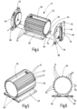
- the tank unit 32 is now shown in more detail. This is how it shows Fig. 4 the tank unit 32 in the manner of an exploded view with a housing 52, which is designed as an extruded profile, preferably made of aluminum. Along its outer circumference, the housing 52 has axially continuous cooling fins 54, which are an integral part of the extruded profile.
- the cooling fins 54 mentioned are interrupted by two flat profiles 56 and a flange plate 58 on the underside of the housing 52, viewed in the circumferential direction.
- the two flat profiles 56 can be used to carry an unspecified machine plate from the manufacturer and, as a further attachment, a level meter or sensor (not shown).
- the flange plate 58 serves to horizontally support the unit presented, as exemplified in the Fig. 1 is shown.
- the flange plate 58 mentioned is an integral part of the cylindrical housing body 52 of the tank unit 32 and is a hollow profile, as shown in particular in the illustrations 5 and 6 resulted, conceived.
- Two cooling channels 60 run along the tank unit 32 between the flange plate 58 and the cylindrical jacket of the housing 52.
- the housing 52 is accommodated between two add-on components 62, 64, which are viewed in the direction of the Fig. 4 Seen, right connection component (tank base) 62 on the stand of the unit as shown in the illustration Fig. 2 can serve or the flange 62 has an attachment on the bottom in the form of a fill level sensor 66, which then ensures a horizontal installation position of the unit, as in Fig. 1 presented, pretends.
- left connection component (tank adapter) 64 carries at its upper right end the filling neck 40 for the tank unit 32 and closes in succession, as in the Fig. 1 shown, to the annular flange 30 with the radial piston pump 24.
- the two flanges 62, 64 have connection points 68 with which a cooling circuit (not shown) can be implemented, in which, according to the arrow representations, the coolant enters at the connection point 68 of the tank base 62, is then forwarded to the two cooling channels 60 and collected by the tank adapter 64, the correspondingly heated coolant via the connection point 68, which in turn leaves the tank unit 32.
- a cooling circuit (not shown) can be implemented, in which, according to the arrow representations, the coolant enters at the connection point 68 of the tank base 62, is then forwarded to the two cooling channels 60 and collected by the tank adapter 64, the correspondingly heated coolant via the connection point 68, which in turn leaves the tank unit 32.
- the cooling fins 54 shown serve primarily for air and convection cooling of the tank contents
- the cooling channels 60 enable integrated liquid cooling for the tank contents of the tank unit 32.
- cooling lubricant As a cooling medium, since a Cooling lubricant supply is often already integrated as a unit in the machine tool.
- other cooling media such as water, glycol, etc. are also used. Due to the temperature difference, the cooling medium along the tank profile absorbs the heat of the oil container and thus also of the hydraulic oil that is stored in the tank unit 32.
- the coolant inlet is located at the tank base 62 and the outlet is at the tank adapter 64.
- This cooling process achieves saturation of the oil temperature below the permitted maximum temperature in certain applications.
- electric motors with appropriate operating modes are used. This solves the two thermal problem areas (oil temperature and engine temperature) of the hydraulic unit for the two operating modes mentioned.
- the hydraulic fluid is cooled very well and thus higher operating modes and duty cycles can be achieved with the unit in operation.
- These cooling methods are available both in horizontal ( Fig. 1 ) as well as vertically ( Fig. 2 ) Alignment of the unit can be used.
- the through holes 70 on the tank base 62 can also be provided with screw connections (not shown).
- Fig. 7 a low-pressure single-circuit system, wherein the gear pump 34 designed as a low-pressure pump feeds into a single supply connection P of the hydraulic single-circuit system, not shown.
- the fluid coming from the low-pressure system is returned via the tank connection T into the tank unit 32 for further removal.
- the removal takes place via the removal nozzle 36 and the low-pressure filter element 45 connected to it, so that the fluid then reaches the suction side of the gear pump 34.
- the connections P, T serve as an interface for fluid transfer to a linking system, not shown, of a hydraulic circuit, which is designed here as a single-circuit system.
- the gear pump 34 delivers the fluid on its pressure side to the supply port P of the single-circuit system.
- Fig. 8 is in this respect compared to the embodiment according to Fig. 7 changed as two low-pressure gear pumps 34 now supply a common supply connection P.
- one of the two pumps 34 can be switched to unpressurized circulation as required in order to save energy, work more efficiently and enable a variable volume flow at two operating points.
- a two-circuit system is implemented via the pressure supply connections P1, P2, once with high pressure (P1) and once with low pressure (P2).
- each supply connection P1, P2 being assigned its own supply line 72, which is supplied by the radial piston pump 24.
- a number of pistons, for example three pistons or pump elements 26 can be assigned to the circuit with the supply connection P1 and the remaining pistons or pump elements 26 then supply the second circuit via the further one Supply connection P2.
- the unit appears as a high-quality product with a clear visual order through obvious adjustments to the transitions of the components mentioned in a clearly structured form, which helps facilitate assembly and repair work.
- a very flexible modular system with a uniform structure is available.
- it can be more cost-effective to create a unit with a radial piston pump 24 and a gear pump 34 and, depending on requirements, to put only one of the two pumps 24, 34 or both pumps 24, 34 into operation than each to design an independent high or low pressure unit that only has a specially adapted supply pump.
Landscapes
- Engineering & Computer Science (AREA)
- Mechanical Engineering (AREA)
- General Engineering & Computer Science (AREA)
- Details Of Reciprocating Pumps (AREA)
Description
- Die Erfindung betrifft eine Motor-Pumpenvorrichtung mit den Merkmalen im Oberbegriff von Anspruch 1.
- Solche Vorrichtungen werden fachsprachlich auch als Motor-Pumpen-Aggregate bezeichnet und dienen vorrangig der Versorgung hydraulischer Kreisläufe mit Hydrauliköl vorgebbaren Druckes. Die genannten Aggregate zeichnen sich regelmäßig durch eine hohe Leistungsdichte bei kleinen Abmessungen aus und können für die angesprochene Druckölversorgung ölhydraulischer Anlagen diesen als funktionsfähige Baueinheit beigestellt werden.
- Ein solches hydraulisches Kompaktaggregat ist beispielhaft in der
DE 196 52 706 A1 aufgezeigt, das als Tankeinheit einen ringzylindrischen Druckmittelbehälter aufweist, der über eine äußere Außenwand und eine innere Außenwand sowie über zwei stirnseitige Flansche verfügt, mit einem vom Druckmittelbehälter umgebenen, durch einen Kühlluftstrom gekühlten geschlossenen Elektromotor und mit einer vom Elektromotor antreibbaren Hydropumpe als Versorgungspumpe des jeweiligen hydraulischen Kreislaufs. Angestrebt wird hierbei, dass ein solches Aggregat bei für einen Dauerbetrieb ausreichender Kühlung des Elektromotors, insbesondere in Form eines Anbaugerätes, sehr kompakt aufbaut. Bei der bekannten Lösung wird dies dadurch erreicht, dass der Druckmittelbehälter den Elektromotor eng umgibt und die innere Außenwand des Druckmittelbehälters mit Kühlrippen versehen als Leitmittel für den über den Elektromotor streichenden Kühlluftstrom dient. Auf diese Weise wird die gesamte, zwischen dem Elektromotor und dem Druckmittelbehälter hindurchströmende Luft vollumfänglich zur Kühlung des Elektromotors genutzt und streicht auch an den einem Lüfterrad entfernten Wickelköpfen des Elektromotors eng an dessen Gehäuse entlang. - Die
DE 299 06 881 U1 offenbart eine Motor-Pumpenvorrichtung mit den Merkmalen im Oberbegriff von Anspruch 1, als Baukastensystem konzipiert, bestehend aus mindestens einem Elektromotor, wobei ein Rotor des Elektromotors mit einer Antriebswelle desselben verbunden ist, die endseitig in Lagerstellen drehbar gelagert ist, und wobei zwischen den endseitigen Lagerstellen noch eine weitere dritte Lagerstelle vorhanden ist, die in einem mehrteiligen Motorgehäuse des Elektromotors an einer Innenwand aufgenommen ist, einer von dem Elektromotor jeweils antreibbaren Radialkolbenpumpe, die vorzugsweise einer Hochdruckversorgung dient, und/oder einer Zahnradpumpe, die vorzugsweise einer Niederdruckversorgung dient, einer Tankeinheit, und Anbauteilen, wie Ventilen in Längsverkettung und Füllstandsmesser, wobei für eine Realisierung eines hydraulischen Ein- oder Mehrkreissystems, jede zum Einsatz kommende Versorgungspumpe einen eigenen Versorgungsanschluss für den jeweiligen Kreis des zum Einsatz kommenden Systems aufweist, oder mehrere eingesetzte Versorgungspumpen in einen gemeinsamen Versorgungsanschluss fördern, oder eine einzelne Versorgungspumpe, die vorzugsweise der Hochdruckförderung dient, mehrere Versorgungsstränge aufweist, die jeweils an einen Versorgungsanschluss angeschlossen sind. - Die
EP 2 241 753 A1 und dieEP 2 025 934 A1 offenbaren weitere Motor-Pumpenvorrichtungen. - Ausgehend von diesem Stand der Technik liegt der Erfindung die Aufgabe zugrunde, die vorstehend genannten Aggregate dahingehend weiter zu verbessern, dass trotz ihrer kompakten Bauweise und der hohen spezifischen Leistung diese derart thermisch vorteilhaft ausgebildet sind, dass sie im ununterbrochenen periodischen Betrieb (S6) bis hin zum Dauerbetrieb (S1) zwanglos eingesetzt werden können.
- Eine dahingehende Aufgabe löst eine Motor-Pumpenvorrichtung, die als Baukastensystem konzipiert ist, gemäß der Merkmalsausgestaltung des Patentanspruchs 1.
- Gemäß dem Kennzeichen von Anspruch 1 ist vorgesehen, dass das Gehäuse der Tankeinheit, als Strangpressprofil ausgebildet, entlang seines, der Umgebung zugewandten Außenumfangs axial durchlaufende Kühlrippen aufweist, die einstückiger Bestandteil des Strangpressprofiles sind, dass das Gehäuse der Tankeinheit als zylindrischer Körper ausgebildet ist und dass entlang seines Außenumfangs eine Flanschplatte angeordnet ist, die einstückig in den zylindrischen Körper übergeht und dass diese Flanschplatte den Einbau der Motor-Pumpenvorrichtung in horizontaler Einbaulage und ein Tankfuß die vertikale Einbaulage erlaubt.
- Mit den Merkmalen des Patentanspruchs 1 in seiner Gesamtheit lässt sich eine Motor-Pumpenvorrichtung für den Erhalt einer Vielzahl von Drucckombinationen in der Praxis aufbauen. Durch die angesprochene Verwendung unterschiedlicher Versorgungspumpen, Pumpengrößen, Motoren, Einbaulagen, Tanklängen etc., ergibt sich eine sehr hohe Variantenvielfalt, die je nach vorliegendem Anwendungsfall für das Aggregat aus thermischer Sicht derart ausgelegt werden kann, dass ein ununterbrochener periodischer Betrieb (S6) bis hin zum Dauerbetrieb (S1) möglich ist. Die jeweils genaue Einschaltdauer ist dabei in Abhängigkeit von der Abgabeleistung des Aggregats sowie den Betriebs- und Umgebungsbedingungen derart zu wählen, dass eine maximal zulässige Betriebstemperatur, beispielsweise in Form der Öltemperatur im Aggregat, von vorzugsweise 80°C nicht überschritten wird. Zur selbständigen Überwachung der Betriebstemperatur kann vorzugsweise ein Temperaturschalter in oder außerhalb des Aggregats eingesetzt werden.
- Die Besonderheiten der Motor-Pumpenvorrichtung beruhen auf dem erfindungsgemäßen flexiblen Baukastensystem gemäß der Merkmalsausgestaltung des Patentanspruchs 1, welches unter anderem die Kombination von Hoch- und/oder Niederdruck mit nur einem Aggregat ermöglicht. Dergestalt ist auch die Realisierung von sog. Ein- bis zu Zwei-Kreisversorgungssystemen möglich. Das erfindungsgemäße Aggregat kann sowohl horizontal als auch vertikal eingesetzt werden und die Tankeinheit in Form des Ölbehälters kann flexibel auf das jeweils benötigte Ölvolumen eingestellt werden.
- Für die vorstehend genannten Betriebsarten (S1 und S6) ist bei der Motor-Pumpenvorrichtung vorgesehen, dass das Gehäuse ihrer Tankeinheit als Strangpressprofil ausgebildet entlang ihres der Umgebung zugewandten Außenumfangs mit Kühlrippen versehen ist. Dank des vorzugsweise außenliegenden Elektromotors und dem angesprochenen berippten Tankaußenprofil, vorzugsweise aus Aluminiummaterial hergestellt, ist die erwünscht erhöhte Betriebsart dergestalt realisierbar. Insbesondere bei Einsatz eines integrierten Kühlsystems über mindestens einen Kühlkanal im Stranggussprofil der Tankeinheit lassen sich zusätzlich Kühlmaßnahmen vermeiden, wie beispielsweise das Anbringen eines Lüfters, dessen Lüfterrad über eine Antriebswelle von dem Elektromotor neben der jeweiligen Versorgungspumpe mit anzutreiben ist, was zu entsprechenden Verlusten im Betrieb der bekannten Aggregate führt. Weiterhin kann somit in bestimmten Anwendungsfällen auf einen zusätzlichen Ölkühler verzichtet werden.
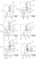
- Weitere vorteilhafte Ausführungsformen der erfindungsgemäßen Lösung sind Gegenstand der weiteren Unteransprüche. Im Folgenden wird die aggregatartige Motor-Pumpenvorrichtung anhand der Zeichnung näher erläutert. Dabei zeigen in prinzipieller und nicht maßstäblicher Darstellung die
- Fig. 1
- in perspektivischer Schrägansicht die Motor-Pumpenvorrichtung als Ganzes;
- Fig. 2
- in der Art eines Längsschnitts eine Seitendarstellung auf die Motor-Pumpenvorrichtung nach der
Fig. 1 in vertikal aufgeständerter Bauweise; - Fig. 3
- eine Ansicht durch die Motor-Pumpenvorrichtung längs der Linie III - III in
Fig. 2 ; - Fig. 4 bis 6
- in verschiedenen Darstellungen Teile einer Tankeinheit, wie sie für die Motor-Pumpenvorrichtung nach den
Fig. 1 und2 eingesetzt ist; und - Fig. 7 bis 12
- in der Art hydraulischer Schaltplandarstellungen verschiedene Einsatzmöglichkeiten der Motor-Pumpenvorrichtung für verschiedene hydraulische Ein- und Zweikreissysteme.
- Die erfindungsgemäße Motor-Pumpenvorrichtung eignet sich als Hoch-Niederdruck-Aggregat besonders für:
- Pressen und Umformmaschinen,
- Spannen, Klemmen, Lösen, Indexieren an Werkzeugmaschinen,
- hydraulische Werkzeuge als Antriebsaggregate,
- Spannhydraulik,
- Betätigung von Hebe- und Schwenkeinrichtungen,
- Hilfs- und Nebenantriebe,
- andere kundenspezifische Anwendungen.
- Für die dahingehenden Anwendungen lässt sich die in
Fig. 1 als Ganzes von außen dargestellte Motor-Pumpenvorrichtung, wie dargestellt, horizontal als auch vertikal gemäß der Längsschnittdarstellung nach derFig. 2 einsetzen. Die in derFig. 2 dargestellte Motor-Pumpenvorrichtung ist als Baukastensystem konzipiert und weist einen als Ganzes mit 10 bezeichneten Elektromotor auf. Der Elektromotor 10 kann aus einer üblichen Asynchronmaschine bestehen mit einem außenliegenden Stator 12 und einem innenliegenden Rotor 14 (sieheFig. 2 ). Der Rotor 14 ist in üblicher Weise mit einer Antriebswelle 16 des Elektromotors 10 verbunden, die endseitig in Lagerstellen 18 drehbar gelagert ist. Zwischen den endseitigen Lagerstellen 18 ist noch eine weitere dritte Lagerstelle 20 vorhanden, die in dem mehrteiligen Motorgehäuse 22 des Elektromotors 10 an einer Innenwand aufgenommen ist. Weiterhin kann der Elektromotor 10 mit oder ohne Lüfterrad ausgestattet werden; hier inFig. 1 und2 mit Lüfterrad dargestellt. - In Blickrichtung auf die
Fig. 2 gesehen, ist unterhalb des Motorgehäuses 22 eine Radialkolbenpumpe 24 eingebaut mit insgesamt drei Pumpenelementen 26 gemäß der Darstellung nach derFig. 3 . Anstelle von drei Kolben oder Pumpenelementen 26 können auch sechs Kolben oder Pumpenelementen für die Radialkolbenpumpe eingesetzt sein. Die angesprochenen drei oder sechs ventilfedergesteuerten Radialkolben-Pumpenelemente 26 werden drehrichtungsunabhängig durch einen Exzentertrieb 28 betätigt, welcher von dem außenliegenden Elektromotor 10, und zwar über dessen Antriebswelle 16, angetrieben wird. - Ferner sind die in der
Fig. 3 gezeigten Pumpenelemente 26 in einem Pumpengehäuse in der Art eines Ringflansches 30 aufgenommen. Dieser Ringflansch 30 ist, wie dies insbesondere dieFig. 2 zeigt, zwischen dem Elektromotor 10 und einer als Ganzes mit 32 bezeichneten Tankeinheit der Motor-Pumpenvorrichtung aufgenommen. Das Innere der Tankeinheit 32 dient der Aufnahme einer vorgebbaren Ölfluidmenge. Ferner ist innerhalb der Tankeinheit 32 eine Zahnradpumpe 34 integriert, deren technischer Aufbau üblich und daher nicht mehr näher dargestellt ist. Die Zahnradpumpe 34 entnimmt, in Blickrichtung auf dieFig. 2 gesehen, auf ihrer Unterseite über einen Entnahmestutzen 36 mit Filterelement 45 Fluid aus der Tankeinheit 32 für die weitere Förderung aus dem Aggregat hinaus in ein Ein- oder Zweikreissystem einer hydraulischen Gesamtanlage (nicht dargestellt). Auch die Radialkolbenpumpe 24 weist eine Saugleitung 38 mit Filterelement 39 auf zwecks Filtrieren des aus dem Tank 32 mittels der Radialkolbenpumpe 24 entnommenen Öls, das gleichfalls von dem Hydraulikaggregat nach außen hin an einen hydraulischen Verbraucher, wie eingangs beschrieben, abgegeben wird. - Die Abtriebswelle 42 der Zahnradpumpe 34, die in der
Fig. 2 nur prinzipiell und schematisch wiedergegeben ist, wird von der Antriebswelle 16 des Elektromotors 10 über eine sog. Oldham-Kupplung 44 angetrieben. Jedenfalls sind die stutzenartigen Fluid-Entnahmeteile, unter anderem die Saugleitungen 36 und 38, derart konzipiert, dass eine Fluidentnahme aus dem Tank 32 sowohl in einer horizontalen Einbaulage des Aggregats gemäß der Darstellung nach derFig. 1 erfolgen kann als auch eine vertikale Aufständerung des Aggregats gemäß der Darstellung nach derFig. 2 ermöglicht ist. Für das Befüllen des Tanks 32 ist der Belüftungsfilter 40 zu entnehmen (Fig. 1 ,3 ). - Was sich noch näher aus den
Fig. 7 bis 12 ergeben wird, lässt sich die erfindungsgemäße Motor-Pumpenvorrichtung derart mit Radialkolbenpumpen 24 und/oder mit Zahnradpumpen 34 ausstatten, dass eine Druckversorgung für hydraulische Ein- und Zweikreissysteme möglich ist, und zwar nur im Niederdruck (ND) oder nur im Hochdruck (HD) oder entsprechend Niederdruck (ND) und Hochdruck (HD) miteinander kombiniert. Dabei ist erfindungsgemäß vorgesehen, dass die jeweilige Radialkolbenpumpe 24 der Hochdruckversorgung und die jeweils eingesetzte Zahnradpumpe 34 der Niederdruckversorgung eines hydraulischen Kreislaufs dienen soll. Je nach angestrebtem Leistungsvermögen für den Elektromotor 10 kann dieser zwei- oder vierpolig ausgebildet sein, und ist das in derFig. 1 dargestellte Aggregat nur für reine Niederdruckanwendungen im Dauerbetrieb vorgesehen, kann ein in derFig. 1 von außen dargestellter Dämpfungsring 46 zwischen dem Ringflansch 30 und dem Gehäuse 22 des Elektromotors 10 auch entfallen oder aufgrund einer anderen Pumpenansteuerung ersetzt werden. - Insbesondere kann für ein Einkreissystem dieses mit Hochdruck (HD), Niederdruck (ND), Hoch- und Niederdruck (HN) und mit Niederdruck/Niederdruck (NN) versorgt werden. Bei einem Zweikreissystem erfolgt die Versorgung mit Niederdruck/Niederdruck (N-N), Hochdruck/Hochdruck (H-H) oder mit Hoch-/Niederdruck (H-N). Je nach angesprochener Versorgungsart mit Hochdruck oder mit Niederdruck kann gemäß dem hier vorgestellten Baukastensystem auch nur eine radiale Kolbenpumpe 24 als Hochdruckpumpe oder nur eine Zahnradpumpe 34 als Niederdruckpumpe zum Einsatz kommen; ansonsten bleiben alle anderen Baukomponenten, wie beispielhaft in der
Fig. 2 dargestellt, erhalten. Lediglich bei reinen Niederdruck-Varianten (N; NN; N-N) kann je nach Anwendung mit einer abweichenden Motor-Pumpenanbindung gearbeitet werden. Die angesprochene Hochdruckpumpe kann bei Fördermengen von etwa 3l/Minute durchaus 700 bar Versorgungsdruck zur Verfügung stellen. Die Niederdruckpumpe hat hingegen eine höhere Fördermenge bis zu beispielsweise 8,6 l/min bei 250 bar oder von beispielsweise 20l/Minute bei 110 bar Versorgungsdruck. Werden zwei Niederdruck-Versorgungspumpen miteinander kombiniert, so kann im Einkreisbetrieb (NN) eine der Pumpen zur Energieeinsparung je nach Bedarf in den drucklosen Umlauf geschaltet werden. Weiterhin können die Pumpen im Zweikreissystem (N-N; H-N; H-H) alternierend oder auch parallel betrieben werden. Die dahingehenden Werte sind nur beispielhaft und können je nach Anwendungsfall entsprechend angepasst werden. - Wie sich aus der
Fig. 1 weiter ergibt, ist am Außenumfang des Motorgehäuses 22 ein elektrischer Anschlusskasten 50 vorhanden. Am Pumpenflansch 30 ist mindestens eine Längsverkettung, als Ganzes mit 48 bezeichnet samt Ventilen, befestigt. Eine Füllstandsanzeige des Behälterinhaltes kann für die horizontale Bauweise an einem Tankfuß 62 und für die vertikale Bauweise am Tankgehäuse 52 integriert werden. - In den
Fig. 4 bis 6 ist nunmehr die Tankeinheit 32 detaillierter wiedergegeben. So zeigt dieFig. 4 die Tankeinheit 32 in der Art einer Explosionsdarstellung mit einem Gehäuse 52, das als Strangpressprofil, vorzugsweise aus Aluminium bestehend, ausgebildet ist. Entlang seines Außenumfanges weist das Gehäuse 52 axial durchlaufende Kühlrippen 54 auf, die einstückiger Bestandteil des Strangpressprofiles sind. Die genannten Kühlrippen 54 sind von zwei Flachprofilen 56 sowie einer Flanschplatte 58 auf der Unterseite des Gehäuses 52 in Umfangsrichtung gesehen unterbrochen. Die beiden Flachprofile 56 können dazu verwendet werden, ein nicht näher spezifiziertes Maschinenschild des Herstellers zu tragen sowie als weiteres Anbauteil einen Füllstandsmesser oder Sensor (nicht dargestellt). Die Flanschplatte 58 hingegen dient der horizontalen Aufständerung des vorgestellten Aggregates, wie dies beispielhaft in derFig. 1 gezeigt ist. Die genannte Flanschplatte 58 ist einstückiger Bestandteil des an sich zylindrischen Gehäusekörpers 52 der Tankeinheit 32 und ist als Hohlprofil, wie dies insbesondere die Darstellungen nach denFig. 5 und 6 ergeben, konzipiert. Zwischen der Flanschplatte 58 und dem zylindrischen Mantel des Gehäuses 52 verlaufen entlang der Tankeinheit 32 zwei Kühlkanäle 60. - Wie sich des Weiteren aus der
Fig. 4 ergibt, ist das Gehäuse 52 zwischen zwei Anbaukomponenten 62, 64 aufgenommen, wobei die in Blickrichtung auf dieFig. 4 gesehen, rechte Anschlusskomponente (Tankfuß) 62 dem Aufständern des Aggregates gemäß der Darstellung nach derFig. 2 dienen kann oder der Flansch 62 weist bodenseitig ein Anbauteil in Form eines Füllstandssensors 66 auf, was dann eine horizontale Einbaulage des Aggregates, wie inFig. 1 dargestellt, vorgibt. Die in Blickrichtung auf dieFig. 4 gesehene, linke Anschlusskomponente (Tankadapter) 64 trägt an seinem oberen rechten Ende den Befüllstutzen 40 für die Tankeinheit 32 und schließt in Hintereinanderfolge, wie in derFig. 1 dargestellt, an den Ringflansch 30 mit der Radialkolbenpumpe 24 an. - Wie sich aus der
Fig. 4 weiter ergibt, weisen die beiden Flansche 62, 64 Anschlussstellen 68 auf, mit denen sich ein nicht näher dargestellter Kühlkreislauf realisieren lässt, bei dem gemäß den Pfeildarstellungen das Kühlmittel an der Anschlussstelle 68 des Tankfußes 62 eintritt, dann an die beiden Kühlkanäle 60 weitergeleitet wird und vom Tankadapter 64 gesammelt, die entsprechend erwärmte Kühlflüssigkeit über die Anschlussstelle 68, die Tankeinheit 32 wiederum verlässt. Dergestalt ist eine wirksame Kühlung des Tankinhalts möglich. Während die aufgezeigten Kühlrippen 54 also vorrangig zur Luft- und Konvektionskühlung des Tankinhalts dienen, ermöglichen die Kühlkanäle 60 eine integrierte Flüssigkeitskühlung für den Tankinhalt der Tankeinheit 32. Als Kühlmedium würde sich bei einem Einsatz des Aggregates bei Werkzeugmaschinen anbieten, auf deren Kühlschmierstoff zurückzugreifen, da eine Kühlschmierstoffversorgung als Einheit oft in der Werkzeugmaschine bereits integriert ist. Es kommen jedoch auch andere Kühlmedien wie Wasser, Glykol etc. zum Einsatz. Dabei nimmt das Kühlmedium entlang des Tankprofils aufgrund der Temperaturdifferenz die Wärme des Ölbehälters und somit auch des Hydrauliköls auf, das in der Tankeinheit 32 bevorratet ist. - Der Kühlflüssigkeitseintritt befindet sich am Tankfuß 62 und der Austritt am Tankadapter 64. Durch dieses Kühlverfahren wird in bestimmten Anwendungsfällen eine Sättigung der Öltemperatur unterhalb der zugelassenen max. Temperatur erreicht. Für den periodischen ununterbrochenen Betrieb bis hin zum Dauerbetrieb werden dementsprechend Elektromotoren mit angemessener Betriebsart eingesetzt. Somit werden die beiden thermischen Problemstellen (Öltemperatur und Motortemperatur) des Hydraulikaggregates für die beiden genannten Betriebsarten gelöst.
- Aufgrund der integrierten Flüssigkeitskühlung sowie einer erhöhten Oberfläche durch die Kühlrippen 54 und einer guten Wärmeleitung durch Einsatz des Werkstoffes Aluminium für das Gehäuse 52 liegt eine sehr gute Kühlung des Hydraulikfluids vor und es können dergestalt höhere Betriebsarten und Einschaltdauern mit dem Aggregat im Betrieb erreicht werden. Diese Kühlverfahren sind sowohl in horizontaler (
Fig. 1 ) als auch in vertikaler (Fig. 2 ) Ausrichtung des Aggregates einsetzbar. Für eine vertikale Einbausituation lassen sich auch die Durchgangslöcher 70 am Tankfuß 62 mit nicht näher dargestellten Schraubverbindungen versehen. - Im Folgenden werden nunmehr die einzelnen Systemlösungen anhand von Beispielen nach den
Fig. 7 bis 12 vorgestellt. - So zeigt die
Fig. 7 ein Niederdruck-Einkreissystem, wobei die als Niederdruckpumpe ausgebildete Zahnradpumpe 34 in einen einzelnen Versorgungsanschluss P des nicht näher dargestellten hydraulischen Einkreissystems einspeist. Das aus dem Niederdrucksystem kommende Fluid wird über den Tankanschluss T in die Tankeinheit 32 für eine erneute Entnahme zurückgegeben. Die Entnahme erfolgt dabei über den Entnahmestutzen 36 und das daran angeschlossene Niederdruck-Filterelement 45, so dass das Fluid dann auf die Saugseite der Zahnradpumpe 34 gelangt. Die Anschlüsse P, T dienen insoweit als Schnittstelle zur Fluid-Weiterführung an ein nicht näher dargestelltes Verkettungssystem eines hydraulischen Kreislaufs, der hier als Einkreissystem konzipiert ist. Ferner gibt die Zahnradpumpe 34 auf ihrer Druckseite das Fluid an den Versorgungsanschluss P des Einkreissystems ab. - Die Lösung nach der
Fig. 8 ist insoweit gegenüber der Ausführungsform nach derFig. 7 geändert, als nunmehr zwei Niederdruck-Zahnradpumpen 34 einen gemeinsamen Versorgungsanschluss P versorgen. Diesbezüglich kann eine der beiden Pumpen 34 nach Bedarf in den drucklosen Umlauf geschaltet werden, um Energie einzusparen, effizienter zu arbeiten und einen variablen Volumenstrom in zwei Arbeitspunkten zu ermöglichen. - Bei der Ausführungsform nach der
Fig. 9 sind zwei Zahnradpumpen 34 für den Niederdruck vorhanden und jede Pumpe 34 als Versorgungspumpe versorgt einen eigenen Versorgungsanschluss P1 sowie P2. Bei den Ausführungsbeispielen nach denFig. 7 bis 9 besteht also die Möglichkeit innerhalb des Aggregats vollständig auf eine Radialkolbenpumpe 24 zu verzichten. Für die Lösung nach denFig., 8 und 9 ist anstelle einer einzelnen Zahnradpumpe 34 nach derFig. 2 zwei Zahnradpumpen vorzusehen. Es besteht aber auch die Möglichkeit, gleich von Anfang an mehrere Zahnradpumpen 34 in die Tankeinheit 32 zu integrieren und dann zur Realisierung der Lösung nach derFig. 7 nur eine der vorhanden Zahnradpumpen 34 in Betrieb zu nehmen. Ferner besteht auch die Möglichkeit, die für die Niederdruckversorgung vorgesehene Zahnradpumpe 34 durch eine Radialkolbenpumpe 24 mit geringerer Leistung für die Niederdruckversorgung im Bedarfsfall zu ersetzen. - Bei der Lösung nach der
Fig. 10 kommt für eine Hochdruckversorgung des Einkreissystems ausschließlich eine Radialkolbenpumpe 24 zum Einsatz, so dass die für den Niederdruckbereich vorgesehenen Zahnradpumpen 34 innerhalb des Aggregats nicht vorgesehen werden. Die Radialkolbenpumpe 24 nach derFig. 10 fördert mit nur einem Versorgungsstrang 72 unter Druck stehendes Fluid in den Druckversorgungsanschluss P. - Bei der Ausführungsform nach der
Fig. 11 wird über einen Versorgungsstrang 72 der Hochdruck-Radialkolbenpumpe 24 der eine Versorgungsanschluss P1 versorgt, wohingegen die Niederdruck-Zahnradpumpe 34 den weiteren Druckversorgungsanschluss P2 mit Druckfluid vorgebbaren Druckes beschickt. Dergestalt ist über die Druckversorgungsanschlüsse P1, P2 ein Zweikreissystem realisiert, einmal mit Hochdruck (P1), einmal mit Niederdruck (P2). Es besteht aber auch im Sinne eines Einkreissystems die Möglichkeit, was nicht näher dargestellt ist, die beiden Versorgungsanschlüsse P1, P2 wiederum über ein Ventil innerhalb der Verkettung fluidführend miteinander zu verbinden, so dass insgesamt ein erhöhter Volumenstrom (HN) erreicht ist gegenüber einer Lösung mit nur einer Hochdruckpumpe, beispielsweise in Form der Radialkolbenpumpe 24 nach derFig. 10 . Weiterhin ist somit bei der Variante HN ein Umschalten zwischen Hoch- und Niederdruck möglich, wie es z.B. in typischen Eil-Schleichgangschaltungen benötigt wird. - Bei der Lösung nach der
Fig. 12 ist wiederum ein Zweikreissystem P1, P2 realisiert, wobei diesmal jedem Versorgungsanschluss P1, P2 ein eigener Versorgungsstrang 72 zugeordnet ist, der von der Radialkolbenpumpe 24 versorgt ist. Insbesondere bei einem Aufbau der Radialkolbenpumpe 24 mit mehreren Kolben, beispielsweise sechs Kolben, lässt sich eine Anzahl von Kolben, beispielsweise drei Kolben oder Pumpenelementen 26 dem Kreis mit dem Versorgungsanschluss P1 zuordnen und die verbleibenden Kolben oder Pumpenelemente 26 versorgen dann den zweiten Kreis über den weiteren Versorgungsanschluss P2. - Wie die
Fig. 1 verdeutlicht, erscheint das Aggregat durch sinnfällige Anpassungen von Übergängen der genannten Bauteile in einer klar strukturierten Form als qualitativ hochwertiges Produkt mit einer klaren visuellen Ordnung, was Montage- und Reparaturarbeiten erleichtern hilft. Durch die Wiederverwendung der genannten Bauteile sowohl in horizontaler als auch vertikaler Einbaulage und der Realisierung unterschiedlicher Systemlösungen und Kreisvarianten liegt ein sehr flexibles Baukastensystem mit einheitlichem Aufbau vor. Es kann im Rahmen des angesprochenen Baukastensystems kostengünstiger sein, ein Aggregat zu erstellen mit einer Radial-Kolbenpumpe 24 und einer Zahnradpumpe 34 und je nach Bedarf immer nur einer der beiden Pumpen 24, 34 oder beide Pumpen 24, 34 in Betrieb zu nehmen, als jeweils ein eigenständiges Hoch- oder Niederdruck-Aggregat zu konzipieren, das nur eine dann jeweils spezielle angepasste Versorgungspumpe aufweist.
Claims (11)
- Motor-Pumpenvorrichtung, als Baukastensystem konzipiert, bestehend aus mindestens- einem Elektromotor (10), wobei ein Rotor (14) des Elektromotors (10) mit einer Antriebswelle (16) desselben verbunden ist, die endseitig in Lagerstellen (18) drehbar gelagert ist, und wobei zwischen den endseitigen Lagerstellen (18) noch eine weitere dritte Lagerstelle (20) vorhanden ist, die in einem mehrteiligen Motorgehäuse (22) des Elektromotors (10) an einer Innenwand aufgenommen ist,- einer von dem Elektromotor (10) jeweils antreibbaren Radialkolbenpumpe (24), die vorzugsweise einer Hochdruckversorgung dient, und/oder einer Zahnradpumpe (34), die vorzugsweise einer Niederdruckversorgung dient,- einer Tankeinheit (32), und- Anbauteilen, wie Ventilen (48) in Längsverkettung und Füllstandsmesser (66),wobei für eine Realisierung eines hydraulischen Ein- oder Mehrkreissystems,- jede zum Einsatz kommende Versorgungspumpe (24, 34) einen eigenen Versorgungsanschluss (P1, P2) für den jeweiligen Kreis des zum Einsatz kommenden Systems aufweist, oder- mehrere eingesetzte Versorgungspumpen (24, 34) in einen gemeinsamen Versorgungsanschluss (P) fördern, oder- eine einzelne Versorgungspumpe (24), die vorzugsweise der Hochdruckförderung dient, mehrere Versorgungsstränge (72) aufweist, die jeweils an einen Versorgungsanschluss (P1, P2) angeschlossen sind,dadurch gekennzeichnet,dass das Gehäuse (52) der Tankeinheit (32), als Strangpressprofil ausgebildet, entlang seines, der Umgebung zugewandten Außenumfangs axial durchlaufende Kühlrippen (54) aufweist, die einstückiger Bestandteil des Strangpressprofiles sind,dass das Gehäuse (52) der Tankeinheit (32) als zylindrischer Körper ausgebildet ist unddass entlang seines Außenumfangs eine Flanschplatte (58) angeordnet ist, die einstückig in den zylindrischen Körper übergeht unddass diese Flanschplatte (58) den Einbau der Motor-Pumpenvorrichtung in horizontaler Einbaulage und ein Tankfuß (62) die vertikale Einbaulage erlaubt.
- Motor-Pumpenvorrichtung nach Anspruch 1, dadurch gekennzeichnet, dass die jeweilige Radialkolbenpumpe (24) zwischen Elektromotor (10) und Tankeinheit (32) aufgenommen ist.
- Motor-Pumpenvorrichtung nach Anspruch 1 oder 2, dadurch gekennzeichnet, dass die jeweilige Zahnradpumpe (34) in der Tankeinheit (32) aufgenommen ist.
- Motor-Pumpenvorrichtung nach einem der vorstehenden Ansprüche, dadurch gekennzeichnet, dass der Elektromotor (10) mit der gemeinsamen Antriebswelle (16) sowohl die jeweilige Radialkolbenpumpe (24) als auch die Zahnradpumpe (34) antreibt.
- Motor-Pumpenvorrichtung nach einem der vorstehenden Ansprüche, dadurch gekennzeichnet, dass der Elektromotor (10) außenliegend das Motorgehäuse (22) aufweist, das an die Umgebung anschließt und an das sich das Pumpengehäuse (30) der Versorgungspumpe (24, 34) anschließt, an das sich wiederum ein Gehäuse (52) der Tankeinheit (32) anschließt.
- Motor-Pumpenvorrichtung nach einem der vorstehenden Ansprüche, dadurch gekennzeichnet, dass der Elektromotor (10), die Versorgungspumpe (24, 34) und die Tankeinheit (32) die wesentlichen Komponenten des Baukastensystems sind.
- Motor-Pumpenvorrichtung nah einem der vorstehenden Ansprüche, dadurch gekennzeichnet, dass der Elektromotor (10) eine Asynchronmaschine ist, mit einem außenliegenden Stator (12) und dem innenliegenden Rotor (14).
- Motor-Pumpenvorrichtung nach einem der vorstehenden Ansprüche, dadurch gekennzeichnet, dass eine Ventillängsverkettung am Pumpenflansch (30) befestigt ist.
- Motor-Pumpenvorrichtung nach einem der vorstehenden Ansprüche, dadurch gekennzeichnet, dass die Kolben (26) der Radialkolbenpumpe (24) über einen Exzentertrieb (28) der Antriebswelle (16) des Elektromotors (10) antreibbar sind und/oder die Abtriebswelle (42) der Zahnradpumpe (34) über eine Oldham-Kupplung (44) mit der Antriebswelle (16) des Elektromotors (10) verbunden ist.
- Motor-Pumpenvorrichtung nach einem der vorstehenden Ansprüche, dadurch gekennzeichnet, dass in den Mantel des Gehäuses (52) der Tankeinheit (32) integriert, vorzugsweise an der Übergangsstelle zwischen Flanschplatte (58) und zylindrischem Mantel des Gehäuses (52), mindestens ein Kühlkanal (60) vorhanden ist.
- Motor-Pumpenvorrichtung nach einem der vorstehenden Ansprüche, dadurch gekennzeichnet, dass das Gehäuse (52) der Tankeinheit (32) an ihren stirnseitigen Enden zum einen den Tankfuß (62) zum Aufständern der Motor-Pumpenvorrichtung in einer vertikalen Ausrichtung und zum anderen einen weiteren Tankadapter (64) für den Anschluss des Ringflansches (30) mit der jeweiligen Radialkolbenpumpe (24) aufweist.
Applications Claiming Priority (2)
| Application Number | Priority Date | Filing Date | Title |
|---|---|---|---|
| DE102016010669.7A DE102016010669A1 (de) | 2016-08-29 | 2016-08-29 | Motor-Pumpenvorrichtung |
| PCT/EP2017/001026 WO2018041401A1 (de) | 2016-08-29 | 2017-08-29 | Motor-pumpenvorrichtung |
Publications (3)
| Publication Number | Publication Date |
|---|---|
| EP3504433A1 EP3504433A1 (de) | 2019-07-03 |
| EP3504433B1 EP3504433B1 (de) | 2020-04-22 |
| EP3504433B2 true EP3504433B2 (de) | 2024-01-17 |
Family
ID=59791023
Family Applications (1)
| Application Number | Title | Priority Date | Filing Date |
|---|---|---|---|
| EP17761804.8A Active EP3504433B2 (de) | 2016-08-29 | 2017-08-29 | Motor-pumpenvorrichtung |
Country Status (3)
| Country | Link |
|---|---|
| EP (1) | EP3504433B2 (de) |
| DE (1) | DE102016010669A1 (de) |
| WO (1) | WO2018041401A1 (de) |
Cited By (1)
| Publication number | Priority date | Publication date | Assignee | Title |
|---|---|---|---|---|
| DE102024126607A1 (de) * | 2024-09-16 | 2026-03-19 | HMS - Hybrid Motion Solutions GmbH | Adapter für Motorpumpeneinheit, Motorpumpeneinheit und Verfahren zum Betreiben |
Families Citing this family (9)
| Publication number | Priority date | Publication date | Assignee | Title |
|---|---|---|---|---|
| DE102018001725A1 (de) * | 2018-03-05 | 2019-09-05 | Hydac Fluidtechnik Gmbh | Anschlussvorrichtung |
| DE102018111059A1 (de) * | 2018-05-08 | 2019-11-14 | Speck-Kolbenpumpenfabrik Otto Speck Gmbh & Co Kg | Antrieb für eine kolbenpumpe oder einen -kompressor |
| FR3091561B1 (fr) * | 2019-01-03 | 2021-05-28 | Automatisation Et Controle Du Serrage | Microcentrale hydraulique |
| DE102019200703B4 (de) * | 2019-01-21 | 2026-02-05 | Hawe Hydraulik Se | Sensoreinheit, Fluidaggregat mit Sensoreinheit und Verfahren zur Messung von Parametern eines Fluids |
| DE102019206326A1 (de) * | 2019-05-03 | 2020-11-05 | Hawe Hydraulik Se | Pumpengehäuse mit Kühlmittelkanal und Pumpenaggregat |
| DE102019212074A1 (de) * | 2019-08-13 | 2021-02-18 | Robert Bosch Gmbh | Motor-Hydromaschinen-Einheit zum Anbau an ein Hydraulikaggregat |
| CN112032015A (zh) * | 2020-09-03 | 2020-12-04 | 王萍 | 一种逐步驱动式高效水泵 |
| CN115681067B (zh) * | 2022-09-30 | 2025-09-19 | 北京精密机电控制设备研究所 | 一种集驱动控制功能同轴一体化伺服电机泵 |
| CN120351138B (zh) * | 2025-06-25 | 2025-09-12 | 浙江大学 | 伺服电机泵紧凑容腔搅油流动特性的拟实测试装置及其综合测试平台 |
Citations (1)
| Publication number | Priority date | Publication date | Assignee | Title |
|---|---|---|---|---|
| CH596697A5 (en) † | 1975-05-26 | 1978-03-15 | Theodor Meier | Pump set with air-cooled flanged electric motor |
Family Cites Families (13)
| Publication number | Priority date | Publication date | Assignee | Title |
|---|---|---|---|---|
| DE2021210A1 (de) | 1970-04-30 | 1971-11-11 | Bbc Brown Boveri & Cie | Anordnung fuer den Anbau eines Elektromotors an eine Hydraulik-Pumpe |
| DE9405871U1 (de) | 1994-04-08 | 1994-06-01 | Heilmeier & Weinlein Fabrik für Oel-Hydraulik GmbH & Co KG, 81673 München | Hydraulisches Motorpumpenaggregat |
| DE19652706A1 (de) | 1995-12-22 | 1997-06-26 | Rexroth Mannesmann Gmbh | Hydraulisches Kompaktaggregat |
| DE19615053A1 (de) | 1996-04-17 | 1997-10-23 | Teves Gmbh Alfred | Elektromotor-/Pumpenaggregat |
| DE29609702U1 (de) | 1996-05-31 | 1996-08-29 | Fa. Ursula Schickedanz, 73033 Göppingen | Bügeleisen |
| DE29906881U1 (de) | 1999-04-16 | 1999-07-01 | Heilmeier & Weinlein | Elektrohydraulisches Motorpumpenaggregat |
| DE19942567A1 (de) | 1999-09-07 | 2001-03-22 | Fluidtech Gmbh | Vorrichtung zum Pumpen von Fluid |
| DE20007554U1 (de) | 2000-04-26 | 2000-08-10 | Heilmeier & Weinlein Fabrik für Oel-Hydraulik GmbH & Co KG, 81673 München | Motor-Pumpenaggregat |
| DE102004058624A1 (de) | 2004-12-04 | 2006-06-08 | Hydac Fluidtechnik Gmbh | Baukastensystem für Fluidpumpenvorrichtungen |
| EP2025934B1 (de) | 2007-08-07 | 2009-08-05 | HAWE Hydraulik SE | Motorpumpenaggregat |
| ES2389633T3 (es) * | 2009-04-15 | 2012-10-29 | Hawe Hydraulik Se | Grupo motobomba |
| DE102014103958A1 (de) | 2014-03-21 | 2015-09-24 | Eckerle Industrie-Elektronik Gmbh | Motor-Pumpen-Einheit |
| DE102015115841B4 (de) | 2015-09-18 | 2024-04-18 | Schwäbische Hüttenwerke Automotive GmbH | Pumpen-Motor-Einheit mit einer Kühlung eines die Pumpe antreibenden Elektromotors mittels Leckagefluid |
-
2016
- 2016-08-29 DE DE102016010669.7A patent/DE102016010669A1/de not_active Withdrawn
-
2017
- 2017-08-29 EP EP17761804.8A patent/EP3504433B2/de active Active
- 2017-08-29 WO PCT/EP2017/001026 patent/WO2018041401A1/de not_active Ceased
Patent Citations (1)
| Publication number | Priority date | Publication date | Assignee | Title |
|---|---|---|---|---|
| CH596697A5 (en) † | 1975-05-26 | 1978-03-15 | Theodor Meier | Pump set with air-cooled flanged electric motor |
Cited By (1)
| Publication number | Priority date | Publication date | Assignee | Title |
|---|---|---|---|---|
| DE102024126607A1 (de) * | 2024-09-16 | 2026-03-19 | HMS - Hybrid Motion Solutions GmbH | Adapter für Motorpumpeneinheit, Motorpumpeneinheit und Verfahren zum Betreiben |
Also Published As
| Publication number | Publication date |
|---|---|
| EP3504433A1 (de) | 2019-07-03 |
| EP3504433B1 (de) | 2020-04-22 |
| DE102016010669A1 (de) | 2018-03-01 |
| WO2018041401A1 (de) | 2018-03-08 |
Similar Documents
| Publication | Publication Date | Title |
|---|---|---|
| EP3504433B2 (de) | Motor-pumpenvorrichtung | |
| DE3820003C2 (de) | ||
| EP1731762B1 (de) | Pumpenaggregat | |
| DE10331216B3 (de) | Fluidkühlvorrichtung | |
| WO2015124248A2 (de) | Kompaktaggregat | |
| EP1574714B1 (de) | Pumpenaggregat | |
| DE102020203459A1 (de) | Getriebeölfiltermodul | |
| EP1756434B1 (de) | Baueinheit | |
| DE29906881U1 (de) | Elektrohydraulisches Motorpumpenaggregat | |
| DE102020207028A1 (de) | Pumpeneinheit | |
| EP1633962A1 (de) | Fluidkühlvorrichtung | |
| DE102004001268A1 (de) | Geberzylinder für Kupplungsausrücksysteme | |
| DE102004049883A1 (de) | Hydrauliksystem zur Bereitstellung einer Hilfskraft für eine Kraftfahrzeugeinrichtung | |
| EP2022990B1 (de) | Werkzeugmaschine und Versorgungsaggregat | |
| DE102007036032A1 (de) | Unterwassermotor mit Wärmetauscher | |
| EP1815204B1 (de) | Rohrbündelhochdruckwärmetauscher | |
| EP1774152A1 (de) | Ölmodul mit wasserpumpe und wärmetauscher | |
| DE2331917A1 (de) | Pumpaggregat | |
| DE10256189A1 (de) | Hydraulisches Aggregat | |
| EP1717208B1 (de) | Vorrichtung zur Fluidbehandlung, insbesondere Abwasserbehandlung, mit einem Scheibenstapel | |
| WO2013050099A1 (de) | Anordnung eines ölmoduls und einer ölpumpe an einer verbrennungskraftmaschine | |
| WO2008062023A1 (de) | Umlaufverdrängermaschine | |
| EP0465956B1 (de) | Pumpvorrichtung | |
| DE1628156A1 (de) | Gekapselter Motorverdichter,insbesondere fuer Kleinkaeltemaschinen | |
| DE102013211185A1 (de) | Spindelverdichter-Gehäuse |
Legal Events
| Date | Code | Title | Description |
|---|---|---|---|
| STAA | Information on the status of an ep patent application or granted ep patent |
Free format text: STATUS: UNKNOWN |
|
| STAA | Information on the status of an ep patent application or granted ep patent |
Free format text: STATUS: THE INTERNATIONAL PUBLICATION HAS BEEN MADE |
|
| PUAI | Public reference made under article 153(3) epc to a published international application that has entered the european phase |
Free format text: ORIGINAL CODE: 0009012 |
|
| STAA | Information on the status of an ep patent application or granted ep patent |
Free format text: STATUS: REQUEST FOR EXAMINATION WAS MADE |
|
| 17P | Request for examination filed |
Effective date: 20190329 |
|
| AK | Designated contracting states |
Kind code of ref document: A1 Designated state(s): AL AT BE BG CH CY CZ DE DK EE ES FI FR GB GR HR HU IE IS IT LI LT LU LV MC MK MT NL NO PL PT RO RS SE SI SK SM TR |
|
| AX | Request for extension of the european patent |
Extension state: BA ME |
|
| DAV | Request for validation of the european patent (deleted) | ||
| DAX | Request for extension of the european patent (deleted) | ||
| GRAP | Despatch of communication of intention to grant a patent |
Free format text: ORIGINAL CODE: EPIDOSNIGR1 |
|
| STAA | Information on the status of an ep patent application or granted ep patent |
Free format text: STATUS: GRANT OF PATENT IS INTENDED |
|
| INTG | Intention to grant announced |
Effective date: 20191217 |
|
| GRAS | Grant fee paid |
Free format text: ORIGINAL CODE: EPIDOSNIGR3 |
|
| GRAA | (expected) grant |
Free format text: ORIGINAL CODE: 0009210 |
|
| STAA | Information on the status of an ep patent application or granted ep patent |
Free format text: STATUS: THE PATENT HAS BEEN GRANTED |
|
| AK | Designated contracting states |
Kind code of ref document: B1 Designated state(s): AL AT BE BG CH CY CZ DE DK EE ES FI FR GB GR HR HU IE IS IT LI LT LU LV MC MK MT NL NO PL PT RO RS SE SI SK SM TR |
|
| REG | Reference to a national code |
Ref country code: CH Ref legal event code: EP |
|
| REG | Reference to a national code |
Ref country code: IE Ref legal event code: FG4D Free format text: LANGUAGE OF EP DOCUMENT: GERMAN |
|
| REG | Reference to a national code |
Ref country code: DE Ref legal event code: R096 Ref document number: 502017004900 Country of ref document: DE |
|
| REG | Reference to a national code |
Ref country code: AT Ref legal event code: REF Ref document number: 1260441 Country of ref document: AT Kind code of ref document: T Effective date: 20200515 |
|
| REG | Reference to a national code |
Ref country code: LT Ref legal event code: MG4D |
|
| REG | Reference to a national code |
Ref country code: NL Ref legal event code: MP Effective date: 20200422 |
|
| PG25 | Lapsed in a contracting state [announced via postgrant information from national office to epo] |
Ref country code: NO Free format text: LAPSE BECAUSE OF FAILURE TO SUBMIT A TRANSLATION OF THE DESCRIPTION OR TO PAY THE FEE WITHIN THE PRESCRIBED TIME-LIMIT Effective date: 20200722 Ref country code: LT Free format text: LAPSE BECAUSE OF FAILURE TO SUBMIT A TRANSLATION OF THE DESCRIPTION OR TO PAY THE FEE WITHIN THE PRESCRIBED TIME-LIMIT Effective date: 20200422 Ref country code: FI Free format text: LAPSE BECAUSE OF FAILURE TO SUBMIT A TRANSLATION OF THE DESCRIPTION OR TO PAY THE FEE WITHIN THE PRESCRIBED TIME-LIMIT Effective date: 20200422 Ref country code: NL Free format text: LAPSE BECAUSE OF FAILURE TO SUBMIT A TRANSLATION OF THE DESCRIPTION OR TO PAY THE FEE WITHIN THE PRESCRIBED TIME-LIMIT Effective date: 20200422 Ref country code: PT Free format text: LAPSE BECAUSE OF FAILURE TO SUBMIT A TRANSLATION OF THE DESCRIPTION OR TO PAY THE FEE WITHIN THE PRESCRIBED TIME-LIMIT Effective date: 20200824 Ref country code: IS Free format text: LAPSE BECAUSE OF FAILURE TO SUBMIT A TRANSLATION OF THE DESCRIPTION OR TO PAY THE FEE WITHIN THE PRESCRIBED TIME-LIMIT Effective date: 20200822 Ref country code: SE Free format text: LAPSE BECAUSE OF FAILURE TO SUBMIT A TRANSLATION OF THE DESCRIPTION OR TO PAY THE FEE WITHIN THE PRESCRIBED TIME-LIMIT Effective date: 20200422 Ref country code: GR Free format text: LAPSE BECAUSE OF FAILURE TO SUBMIT A TRANSLATION OF THE DESCRIPTION OR TO PAY THE FEE WITHIN THE PRESCRIBED TIME-LIMIT Effective date: 20200723 |
|
| PG25 | Lapsed in a contracting state [announced via postgrant information from national office to epo] |
Ref country code: RS Free format text: LAPSE BECAUSE OF FAILURE TO SUBMIT A TRANSLATION OF THE DESCRIPTION OR TO PAY THE FEE WITHIN THE PRESCRIBED TIME-LIMIT Effective date: 20200422 Ref country code: BG Free format text: LAPSE BECAUSE OF FAILURE TO SUBMIT A TRANSLATION OF THE DESCRIPTION OR TO PAY THE FEE WITHIN THE PRESCRIBED TIME-LIMIT Effective date: 20200722 Ref country code: LV Free format text: LAPSE BECAUSE OF FAILURE TO SUBMIT A TRANSLATION OF THE DESCRIPTION OR TO PAY THE FEE WITHIN THE PRESCRIBED TIME-LIMIT Effective date: 20200422 Ref country code: HR Free format text: LAPSE BECAUSE OF FAILURE TO SUBMIT A TRANSLATION OF THE DESCRIPTION OR TO PAY THE FEE WITHIN THE PRESCRIBED TIME-LIMIT Effective date: 20200422 |
|
| PG25 | Lapsed in a contracting state [announced via postgrant information from national office to epo] |
Ref country code: AL Free format text: LAPSE BECAUSE OF FAILURE TO SUBMIT A TRANSLATION OF THE DESCRIPTION OR TO PAY THE FEE WITHIN THE PRESCRIBED TIME-LIMIT Effective date: 20200422 |
|
| REG | Reference to a national code |
Ref country code: DE Ref legal event code: R026 Ref document number: 502017004900 Country of ref document: DE |
|
| PLBI | Opposition filed |
Free format text: ORIGINAL CODE: 0009260 |
|
| PG25 | Lapsed in a contracting state [announced via postgrant information from national office to epo] |
Ref country code: ES Free format text: LAPSE BECAUSE OF FAILURE TO SUBMIT A TRANSLATION OF THE DESCRIPTION OR TO PAY THE FEE WITHIN THE PRESCRIBED TIME-LIMIT Effective date: 20200422 Ref country code: DK Free format text: LAPSE BECAUSE OF FAILURE TO SUBMIT A TRANSLATION OF THE DESCRIPTION OR TO PAY THE FEE WITHIN THE PRESCRIBED TIME-LIMIT Effective date: 20200422 Ref country code: EE Free format text: LAPSE BECAUSE OF FAILURE TO SUBMIT A TRANSLATION OF THE DESCRIPTION OR TO PAY THE FEE WITHIN THE PRESCRIBED TIME-LIMIT Effective date: 20200422 Ref country code: CZ Free format text: LAPSE BECAUSE OF FAILURE TO SUBMIT A TRANSLATION OF THE DESCRIPTION OR TO PAY THE FEE WITHIN THE PRESCRIBED TIME-LIMIT Effective date: 20200422 Ref country code: RO Free format text: LAPSE BECAUSE OF FAILURE TO SUBMIT A TRANSLATION OF THE DESCRIPTION OR TO PAY THE FEE WITHIN THE PRESCRIBED TIME-LIMIT Effective date: 20200422 Ref country code: SM Free format text: LAPSE BECAUSE OF FAILURE TO SUBMIT A TRANSLATION OF THE DESCRIPTION OR TO PAY THE FEE WITHIN THE PRESCRIBED TIME-LIMIT Effective date: 20200422 Ref country code: IT Free format text: LAPSE BECAUSE OF FAILURE TO SUBMIT A TRANSLATION OF THE DESCRIPTION OR TO PAY THE FEE WITHIN THE PRESCRIBED TIME-LIMIT Effective date: 20200422 |
|
| PLAX | Notice of opposition and request to file observation + time limit sent |
Free format text: ORIGINAL CODE: EPIDOSNOBS2 |
|
| 26 | Opposition filed |
Opponent name: HAWE HYDRAULIK SE Effective date: 20210107 |
|
| PG25 | Lapsed in a contracting state [announced via postgrant information from national office to epo] |
Ref country code: SK Free format text: LAPSE BECAUSE OF FAILURE TO SUBMIT A TRANSLATION OF THE DESCRIPTION OR TO PAY THE FEE WITHIN THE PRESCRIBED TIME-LIMIT Effective date: 20200422 Ref country code: PL Free format text: LAPSE BECAUSE OF FAILURE TO SUBMIT A TRANSLATION OF THE DESCRIPTION OR TO PAY THE FEE WITHIN THE PRESCRIBED TIME-LIMIT Effective date: 20200422 |
|
| PG25 | Lapsed in a contracting state [announced via postgrant information from national office to epo] |
Ref country code: MC Free format text: LAPSE BECAUSE OF FAILURE TO SUBMIT A TRANSLATION OF THE DESCRIPTION OR TO PAY THE FEE WITHIN THE PRESCRIBED TIME-LIMIT Effective date: 20200422 |
|
| REG | Reference to a national code |
Ref country code: CH Ref legal event code: PL |
|
| PG25 | Lapsed in a contracting state [announced via postgrant information from national office to epo] |
Ref country code: CH Free format text: LAPSE BECAUSE OF NON-PAYMENT OF DUE FEES Effective date: 20200831 Ref country code: LU Free format text: LAPSE BECAUSE OF NON-PAYMENT OF DUE FEES Effective date: 20200829 Ref country code: LI Free format text: LAPSE BECAUSE OF NON-PAYMENT OF DUE FEES Effective date: 20200831 |
|
| PLBB | Reply of patent proprietor to notice(s) of opposition received |
Free format text: ORIGINAL CODE: EPIDOSNOBS3 |
|
| REG | Reference to a national code |
Ref country code: BE Ref legal event code: MM Effective date: 20200831 |
|
| PG25 | Lapsed in a contracting state [announced via postgrant information from national office to epo] |
Ref country code: SI Free format text: LAPSE BECAUSE OF FAILURE TO SUBMIT A TRANSLATION OF THE DESCRIPTION OR TO PAY THE FEE WITHIN THE PRESCRIBED TIME-LIMIT Effective date: 20200422 |
|
| PG25 | Lapsed in a contracting state [announced via postgrant information from national office to epo] |
Ref country code: BE Free format text: LAPSE BECAUSE OF NON-PAYMENT OF DUE FEES Effective date: 20200831 Ref country code: IE Free format text: LAPSE BECAUSE OF NON-PAYMENT OF DUE FEES Effective date: 20200829 |
|
| GBPC | Gb: european patent ceased through non-payment of renewal fee |
Effective date: 20210829 |
|
| PG25 | Lapsed in a contracting state [announced via postgrant information from national office to epo] |
Ref country code: TR Free format text: LAPSE BECAUSE OF FAILURE TO SUBMIT A TRANSLATION OF THE DESCRIPTION OR TO PAY THE FEE WITHIN THE PRESCRIBED TIME-LIMIT Effective date: 20200422 Ref country code: MT Free format text: LAPSE BECAUSE OF FAILURE TO SUBMIT A TRANSLATION OF THE DESCRIPTION OR TO PAY THE FEE WITHIN THE PRESCRIBED TIME-LIMIT Effective date: 20200422 Ref country code: CY Free format text: LAPSE BECAUSE OF FAILURE TO SUBMIT A TRANSLATION OF THE DESCRIPTION OR TO PAY THE FEE WITHIN THE PRESCRIBED TIME-LIMIT Effective date: 20200422 |
|
| PG25 | Lapsed in a contracting state [announced via postgrant information from national office to epo] |
Ref country code: MK Free format text: LAPSE BECAUSE OF FAILURE TO SUBMIT A TRANSLATION OF THE DESCRIPTION OR TO PAY THE FEE WITHIN THE PRESCRIBED TIME-LIMIT Effective date: 20200422 |
|
| PG25 | Lapsed in a contracting state [announced via postgrant information from national office to epo] |
Ref country code: GB Free format text: LAPSE BECAUSE OF NON-PAYMENT OF DUE FEES Effective date: 20210829 |
|
| REG | Reference to a national code |
Ref country code: AT Ref legal event code: MM01 Ref document number: 1260441 Country of ref document: AT Kind code of ref document: T Effective date: 20220829 |
|
| PG25 | Lapsed in a contracting state [announced via postgrant information from national office to epo] |
Ref country code: AT Free format text: LAPSE BECAUSE OF NON-PAYMENT OF DUE FEES Effective date: 20220829 |
|
| PUAH | Patent maintained in amended form |
Free format text: ORIGINAL CODE: 0009272 |
|
| STAA | Information on the status of an ep patent application or granted ep patent |
Free format text: STATUS: PATENT MAINTAINED AS AMENDED |
|
| 27A | Patent maintained in amended form |
Effective date: 20240117 |
|
| AK | Designated contracting states |
Kind code of ref document: B2 Designated state(s): AL AT BE BG CH CY CZ DE DK EE ES FI FR GB GR HR HU IE IS IT LI LT LU LV MC MK MT NL NO PL PT RO RS SE SI SK SM TR |
|
| REG | Reference to a national code |
Ref country code: DE Ref legal event code: R102 Ref document number: 502017004900 Country of ref document: DE |
|
| PGFP | Annual fee paid to national office [announced via postgrant information from national office to epo] |
Ref country code: DE Payment date: 20250831 Year of fee payment: 9 |
|
| PGFP | Annual fee paid to national office [announced via postgrant information from national office to epo] |
Ref country code: FR Payment date: 20250722 Year of fee payment: 9 |