EP3501689B1 - Dispositif de séparation et d'orientation de pièces en forme de tige - Google Patents
Dispositif de séparation et d'orientation de pièces en forme de tige Download PDFInfo
- Publication number
- EP3501689B1 EP3501689B1 EP18020627.8A EP18020627A EP3501689B1 EP 3501689 B1 EP3501689 B1 EP 3501689B1 EP 18020627 A EP18020627 A EP 18020627A EP 3501689 B1 EP3501689 B1 EP 3501689B1
- Authority
- EP
- European Patent Office
- Prior art keywords
- conveying means
- conveying
- piece goods
- container
- plane
- Prior art date
- Legal status (The legal status is an assumption and is not a legal conclusion. Google has not performed a legal analysis and makes no representation as to the accuracy of the status listed.)
- Active
Links
- 238000000926 separation method Methods 0.000 claims description 5
- 239000011248 coating agent Substances 0.000 claims description 3
- 238000000576 coating method Methods 0.000 claims description 3
- 230000001419 dependent effect Effects 0.000 claims description 3
- 230000003068 static effect Effects 0.000 claims description 3
- 230000032258 transport Effects 0.000 claims description 3
- 238000011161 development Methods 0.000 description 3
- 230000018109 developmental process Effects 0.000 description 3
- 230000000694 effects Effects 0.000 description 3
- 230000006978 adaptation Effects 0.000 description 2
- 239000013590 bulk material Substances 0.000 description 2
- 238000001514 detection method Methods 0.000 description 2
- 230000003287 optical effect Effects 0.000 description 2
- 230000015572 biosynthetic process Effects 0.000 description 1
- 239000000969 carrier Substances 0.000 description 1
- 230000001427 coherent effect Effects 0.000 description 1
- 238000011156 evaluation Methods 0.000 description 1
- 230000000284 resting effect Effects 0.000 description 1
- 230000005641 tunneling Effects 0.000 description 1
Images


Classifications
-
- B—PERFORMING OPERATIONS; TRANSPORTING
- B65—CONVEYING; PACKING; STORING; HANDLING THIN OR FILAMENTARY MATERIAL
- B65G—TRANSPORT OR STORAGE DEVICES, e.g. CONVEYORS FOR LOADING OR TIPPING, SHOP CONVEYOR SYSTEMS OR PNEUMATIC TUBE CONVEYORS
- B65G47/00—Article or material-handling devices associated with conveyors; Methods employing such devices
- B65G47/22—Devices influencing the relative position or the attitude of articles during transit by conveyors
- B65G47/24—Devices influencing the relative position or the attitude of articles during transit by conveyors orientating the articles
-
- B—PERFORMING OPERATIONS; TRANSPORTING
- B21—MECHANICAL METAL-WORKING WITHOUT ESSENTIALLY REMOVING MATERIAL; PUNCHING METAL
- B21J—FORGING; HAMMERING; PRESSING METAL; RIVETING; FORGE FURNACES
- B21J15/00—Riveting
- B21J15/10—Riveting machines
- B21J15/30—Particular elements, e.g. supports; Suspension equipment specially adapted for portable riveters
- B21J15/32—Devices for inserting or holding rivets in position with or without feeding arrangements
-
- B—PERFORMING OPERATIONS; TRANSPORTING
- B23—MACHINE TOOLS; METAL-WORKING NOT OTHERWISE PROVIDED FOR
- B23P—METAL-WORKING NOT OTHERWISE PROVIDED FOR; COMBINED OPERATIONS; UNIVERSAL MACHINE TOOLS
- B23P19/00—Machines for simply fitting together or separating metal parts or objects, or metal and non-metal parts, whether or not involving some deformation; Tools or devices therefor so far as not provided for in other classes
- B23P19/001—Article feeders for assembling machines
- B23P19/002—Article feeders for assembling machines orientating the articles
-
- B—PERFORMING OPERATIONS; TRANSPORTING
- B23—MACHINE TOOLS; METAL-WORKING NOT OTHERWISE PROVIDED FOR
- B23P—METAL-WORKING NOT OTHERWISE PROVIDED FOR; COMBINED OPERATIONS; UNIVERSAL MACHINE TOOLS
- B23P19/00—Machines for simply fitting together or separating metal parts or objects, or metal and non-metal parts, whether or not involving some deformation; Tools or devices therefor so far as not provided for in other classes
- B23P19/001—Article feeders for assembling machines
- B23P19/003—Escapement mechanisms used therewith
-
- B—PERFORMING OPERATIONS; TRANSPORTING
- B23—MACHINE TOOLS; METAL-WORKING NOT OTHERWISE PROVIDED FOR
- B23P—METAL-WORKING NOT OTHERWISE PROVIDED FOR; COMBINED OPERATIONS; UNIVERSAL MACHINE TOOLS
- B23P19/00—Machines for simply fitting together or separating metal parts or objects, or metal and non-metal parts, whether or not involving some deformation; Tools or devices therefor so far as not provided for in other classes
- B23P19/001—Article feeders for assembling machines
- B23P19/004—Feeding the articles from hoppers to machines or dispensers
-
- B—PERFORMING OPERATIONS; TRANSPORTING
- B65—CONVEYING; PACKING; STORING; HANDLING THIN OR FILAMENTARY MATERIAL
- B65G—TRANSPORT OR STORAGE DEVICES, e.g. CONVEYORS FOR LOADING OR TIPPING, SHOP CONVEYOR SYSTEMS OR PNEUMATIC TUBE CONVEYORS
- B65G11/00—Chutes
- B65G11/02—Chutes of straight form
- B65G11/023—Chutes of straight form for articles
-
- B—PERFORMING OPERATIONS; TRANSPORTING
- B65—CONVEYING; PACKING; STORING; HANDLING THIN OR FILAMENTARY MATERIAL
- B65G—TRANSPORT OR STORAGE DEVICES, e.g. CONVEYORS FOR LOADING OR TIPPING, SHOP CONVEYOR SYSTEMS OR PNEUMATIC TUBE CONVEYORS
- B65G47/00—Article or material-handling devices associated with conveyors; Methods employing such devices
- B65G47/02—Devices for feeding articles or materials to conveyors
- B65G47/04—Devices for feeding articles or materials to conveyors for feeding articles
- B65G47/12—Devices for feeding articles or materials to conveyors for feeding articles from disorderly-arranged article piles or from loose assemblages of articles
- B65G47/14—Devices for feeding articles or materials to conveyors for feeding articles from disorderly-arranged article piles or from loose assemblages of articles arranging or orientating the articles by mechanical or pneumatic means during feeding
- B65G47/1492—Devices for feeding articles or materials to conveyors for feeding articles from disorderly-arranged article piles or from loose assemblages of articles arranging or orientating the articles by mechanical or pneumatic means during feeding the articles being fed from a feeding conveyor
-
- B—PERFORMING OPERATIONS; TRANSPORTING
- B65—CONVEYING; PACKING; STORING; HANDLING THIN OR FILAMENTARY MATERIAL
- B65G—TRANSPORT OR STORAGE DEVICES, e.g. CONVEYORS FOR LOADING OR TIPPING, SHOP CONVEYOR SYSTEMS OR PNEUMATIC TUBE CONVEYORS
- B65G47/00—Article or material-handling devices associated with conveyors; Methods employing such devices
- B65G47/22—Devices influencing the relative position or the attitude of articles during transit by conveyors
- B65G47/26—Devices influencing the relative position or the attitude of articles during transit by conveyors arranging the articles, e.g. varying spacing between individual articles
- B65G47/30—Devices influencing the relative position or the attitude of articles during transit by conveyors arranging the articles, e.g. varying spacing between individual articles during transit by a series of conveyors
-
- B—PERFORMING OPERATIONS; TRANSPORTING
- B65—CONVEYING; PACKING; STORING; HANDLING THIN OR FILAMENTARY MATERIAL
- B65G—TRANSPORT OR STORAGE DEVICES, e.g. CONVEYORS FOR LOADING OR TIPPING, SHOP CONVEYOR SYSTEMS OR PNEUMATIC TUBE CONVEYORS
- B65G47/00—Article or material-handling devices associated with conveyors; Methods employing such devices
- B65G47/02—Devices for feeding articles or materials to conveyors
- B65G47/04—Devices for feeding articles or materials to conveyors for feeding articles
- B65G47/12—Devices for feeding articles or materials to conveyors for feeding articles from disorderly-arranged article piles or from loose assemblages of articles
- B65G47/14—Devices for feeding articles or materials to conveyors for feeding articles from disorderly-arranged article piles or from loose assemblages of articles arranging or orientating the articles by mechanical or pneumatic means during feeding
- B65G47/1407—Devices for feeding articles or materials to conveyors for feeding articles from disorderly-arranged article piles or from loose assemblages of articles arranging or orientating the articles by mechanical or pneumatic means during feeding the articles being fed from a container, e.g. a bowl
- B65G47/1442—Devices for feeding articles or materials to conveyors for feeding articles from disorderly-arranged article piles or from loose assemblages of articles arranging or orientating the articles by mechanical or pneumatic means during feeding the articles being fed from a container, e.g. a bowl by means of movement of the bottom or a part of the wall of the container
- B65G47/1471—Movement in one direction, substantially outwards
Definitions
- the present invention relates to a device for separating and aligning pin-shaped piece goods having a head and a shaft, in particular rivets, according to the preamble of claim 1.
- a generic device is from the WO 2007/068129 A1 known.
- the ones from the WO 2007/068129 A1 Known device comprises a funnel-shaped container for receiving piece goods, with a front wall and a rear wall, which are arranged opposite one another and each inclined to the vertical at an angle to the outside, and at least two side walls extending between the front wall and the rear wall.
- a driven conveyor belt is arranged within a recess in the front wall, which is inclined to the vertical at the same angle as the front wall and which conveys the piece goods, preforms of plastic bottles or screws, from an acceptance level in the container to a higher delivery level.
- the piece goods are to be removed individually from the container by means of the conveyor belt, which is subdivided into individual sections by a driver extending across the width of the conveyor belt.
- a driver extending across the width of the conveyor belt.
- Pen-shaped, a head and a shaft having piece goods, such as screws are generally considerably smaller in their dimensions and, due to their contour, tend to get caught in each other, which makes separation by the conveyor belt at least very difficult, since the sections between the Carriers usually pick up more than one screw and convey away.
- the object of the present invention is to develop a device for separating and aligning pin-shaped piece goods having a head and a shaft in such a way that it is characterized by a simplified and more cost-effective structure.
- a device for separating and aligning pin-shaped piece goods having a head and a shaft, in particular rivets comprises an essentially funnel-shaped container for receiving the piece goods, with two wall sections that delimit the container in its front area, and a rear wall, the wall sections and the rear wall being partially opposite each other and each at an angle to the outside to the central transverse plane of the container are arranged inclined.
- the container has an endlessly revolving conveying means which is arranged below a recess, in particular a slot-shaped recess, which spaced the wall sections apart and which conveys piece goods from an acceptance level to a higher-lying delivery level.
- the endlessly revolving conveyor has a conveyor level provided with drivers.
- the slot-shaped recess is delimited by mutually parallel front edges of the V-shaped wall sections tapering towards the conveyor and the front edges above the conveyor or in a plane with the Conveying means open out, and that the drivers are designed as cylindrical pins which are arranged at a distance from one another in the direction of rotation of the conveying means and which extend essentially perpendicular to the conveying plane of the conveying means.
- the wall sections have a first inclination with respect to the central transverse plane, so that a first angle is included between the rear wall and the wall sections.
- the wall sections have a second inclination, so that a second angle is additionally enclosed between the opposing wall sections spaced apart by the recess that is smaller than 90 °.
- the conveying means grasps the piece goods lying on top of the container, in particular rivets, which protrude at least in sections onto the conveying means.
- the drivers capture the piece goods and convey it away.
- the additional inclination of the wall sections at the second angle has the effect that the piece goods are oriented in the longitudinal direction.
- piece goods which are only dragged along by the conveying means or its drivers ie have no direct contact with the drivers of the conveying means, detach themselves from the latter and slide back into the container.
- the separated piece goods can be transferred directly to a downstream device for magazining.
- the width of the slot-shaped recess between the wall sections should correspond at least to the width of the drivers and at most to the length of the piece goods. This makes it possible to avoid wedging the piece goods between the front edges of the wall sections and the conveying means. It is particularly advantageous if the width of the recess essentially corresponds to the width of the driver, which is smaller than the head diameter of the piece goods. It can thereby be achieved that the head of the piece goods can be grasped by the driver, the head itself however not resting on the conveying means, but on the wall sections which delimit the recess.
- the drivers can have a circular cylindrical or polygonal cross section.
- the drivers on the conveyor ensure a permanent movement of the piece goods in the container when they pass through the recess in the funnel. In this way, the effect of a vault or tunnel forming in the area of the recess above the conveying means can be avoided during the continuous removal of the piece goods, since individual piece goods slide in the direction of the recess.
- the drivers are alternately offset in the direction of rotation of the conveying means with respect to the longitudinal axis of the conveying means between its edge region and are the longitudinal axis. In this way, it can be avoided that coherent chains can form from piece goods, which are conveyed away by the endlessly circulating conveying means.
- piece goods conveyed by the conveying means to the delivery level can be transferred to a downstream chute arranged at an angle to the horizontal.
- the slide can have at least one channel or two side-by-side channels with an essentially U-shaped profile, the cross section of the respective channel being wider than the head and narrower than the length of the shaft.
- the number of troughs in the slide can be selected depending on the design of the conveying means. In particular, this can depend on the arrangement of the drivers on the conveyor.
- the inclination of the conveying means can preferably be greater than or equal to 30 ° and less than or equal to 60 °. According to the inclination of the conveying means and the resulting change in the second angle at which the wall sections are inclined to one another, the order of magnitude of the throughput of piece goods conveyed away from the container can be varied. In particular, the inclination of the conveyor can be adjusted as a function of the geometry of the piece goods.
- the recess can extend essentially from the lowest point of the container to the upper edge of the wall sections.
- the conveying plane of the conveying means which is provided with the essentially pin-shaped drivers, thus ensures that the cone of bulk material, which tapers towards the lowest point of the container, is always mixed and loosened in order to avoid arching, i.e. a hollowing out or tunneling in the bulk material cone in sections , the formation of which prevents general cargo from being carried by the conveyor.
- this arrangement enables the container to be emptied completely or almost completely.
- the distance between two channels in the longitudinal direction of the chute can widen from the receiving area to the delivery area.
- the at least one channel can have a coating that minimizes static friction, so that the piece goods can pass through the at least one channel largely without interference.
- a sensor arrangement is arranged in the delivery level or at the height of the delivery level or the delivery level, which is set up to detect geometric properties of the piece goods.
- the separated piece goods can be monitored with regard to compliance with predetermined geometric dimensions.
- the sensor arrangement is set up for the optical detection of the geometric dimensions of the piece goods, in particular rivets.
- the conveyor can be driven electromechanically by an actuator.
- the actuator can be designed as an electric motor which is drivingly connected to a deflection roller of the conveying means.
- the electric motor can be integrated into the pulley.
- the deflection roller can be designed as a rotor of the electric motor.
- the electric motor can preferably be designed as a stepper motor. In this way, precise control can be ensured, since the respective position is known when the stepper motor is started and stopped. It is thus possible to sort out piece goods which have been identified by the sensor arrangement due to deviating geometrical dimensions.
- the sorting out can preferably take place automatically.
- the conveying means can be driven mechanically or pneumatically.
- the pneumatic drive of the conveying means is advantageous since it can be operated largely without wear. Against the background of repeated starting and stopping of the conveying means, this is advantageous in order to be able to sort out piece goods which do not correspond to predetermined geometric dimensions.
- a conveying device can be arranged downstream of the chute, which transports away the piece goods coming from the chute at a conveying speed that is dependent on the drive speed of the conveying means arranged in the container.
- the endlessly rotating conveyor can preferably be designed as a conveyor belt or a link chain.
- the upper run of the conveyor belt forms the conveyor level.
- the conveyor device can be drive-coupled to the conveyor.
- the conveying device can be designed as a further conveyor belt with a conveying surface that revolves endlessly around deflection rollers.
- one of the deflection rollers of the conveyor belt arranged in the container can be connected to one of the deflection rollers of the conveyor device by a belt drive.
- At least one separation element can be provided to subdivide a conveying surface of the conveying device into two mutually spaced, parallel conveying sections which are adapted to the spacing between two channels in the delivery area.
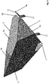
- Fig. 1 shows a perspective view of a separating device 1 for separating and aligning pin-shaped piece goods having a head and a shaft, in particular rivets.
- the device 1 comprises a substantially funnel-shaped container 2 for receiving the piece goods designed as rivets.
- the container 2 has two wall sections 3, 4 which delimit the container 2 in a front area and laterally in sections, and a rear wall 5 which delimits the container 2 in a rear area.
- the rear wall 5, which extends between the wall sections 3, 4, separates the two wall sections 3, 4 from one another in the rear region.
- the wall sections 3, 4 and the rear wall 5 are arranged opposite one another in sections and each inclined to an imaginary central transverse plane 6 of the container 2 at an outward angle so that the essentially funnel-shaped configuration of the container 2 results.
- the two wall sections 3 and 4 are spaced from one another in the front area by a continuous, in particular slot-shaped, recess 7 which extends from the lowest point of the container 2 to the upper edge of the wall sections 3, 4.
- the two wall sections 3, 4 each have a front segment 3a, 4a and a rear segment 3b, 4b.
- the front segments 3a, 4a extend in sections from the recess 7 towards the rear wall 5.
- the front segments 3a, 4a are followed by the rear segments 3b, 4b, which are designed to be inclined at an angle to the front segments 3a, 4a .
- the rear segments 3b, 4b extend as far as the rear wall 5 and are arranged at an angle of approximately 90 ° to the rear wall 5.
- the front segments 3a, 4a have an inclination ⁇ with respect to a longitudinal axis of the recess 7, as can be seen from the illustration in FIG Fig. 4 can be seen.
- an endlessly revolving conveying means designed as a conveyor belt 8 is arranged, which revolves around deflection rollers (not shown in detail) which are arranged at a distance from one another.
- the conveying means can also be designed as a link chain which revolves around corresponding pinions.
- the conveyor belt 8 is inclined at the same angle ⁇ as the wall sections 3, 4 to the central transverse plane 6.
- the conveyor belt 8 conveys the piece goods from the container 2 from an acceptance level in the interior of the container 2 to a higher delivery level above the container 2.
- the acceptance level is variable because it is defined by the respective filling level of the container 2.
- the delivery plane forms the upper deflection point of the conveyor belt 8.
- the conveyor belt 8 is provided with drivers 13 on its conveyor surface 9, which is formed as an upper run.
- the conveyor belt 8 has an inclination ⁇ which is greater than or equal to 30 ° and less than or equal to 60 °.
- a sensor arrangement 22 Positioned in the delivery level or at the level of the delivery level or downstream thereof is a sensor arrangement 22 which is used for the optical detection of geometric dimensions of the separated piece goods. By means of the sensor arrangement 22, piece goods with dimensions deviating from a predeterminable geometric dimension are identified, which enables the identified piece goods to be sorted out, in particular in an automated manner.
- the sensor arrangement 22 is signal-connected to a control device - not shown - which evaluates the signals generated by the sensor arrangement 22.
- control device can be used to control the, in particular automated, sorting.
- conveyance of the piece goods is interrupted by stopping the conveyor belt 8.
- the piece goods that were separated last the geometrical dimension of which deviates from the predetermined geometrical dimension, can be removed manually or automatically.
- the recess 7 is delimited by mutually parallel front edges 10, 11 of the wall sections 3, 4 arranged in a V-shape tapering towards the conveyor belt 8.
- the front edges 10 and 11 open above the conveyor belt 8 or in a plane with the conveying surface 9 of the conveyor belt 8.
- Lugs 12 are provided for attachment to a frame 13 receiving the conveyor belt 8.
- the frame 13 accommodates an actuator system for driving one of the deflection rollers in order to drive the conveyor belt 8 in an endlessly rotating manner.
- the inclination of the front edges 10, 11, which limit the, in particular slot-shaped, recess 7, corresponds to the inclination ⁇ of the conveyor belt 8.
- the pulley can be driven electromechanically, for example by a stepper motor, mechanically or pneumatically.
- the drive of the deflection roller is briefly interrupted for sorting out piece goods which do not correspond to the specified geometric dimensions.
- a slide 13 adjoins the delivery level.
- the chute 13 has two chutes 14 to which the piece goods, i.e. the rivets, from the conveyor belt 8 is passed.
- the grooves 14 have a substantially U-shaped profile.
- the cross section of the grooves 14 is wider than the head and narrower than the length of the shaft of the rivets that are to be separated.
- the distance between the channels 14 widens in the longitudinal direction of the slide from the receiving area to the delivery area.
- the grooves 14 have a coating that minimizes static friction.
- the chute 13 is followed by a conveying device 17, which transports the piece goods coming from the chute 13 at a conveying speed that is dependent on the drive speed of the conveyor belt 8 arranged in the container 2.
- the conveyor device 17 is drivingly coupled to the conveyor belt 8.
- the conveying device 17 can be designed as a further conveyor belt 19 with a conveying surface, which endlessly revolves around deflection rollers.
- one of the deflection rollers of the conveyor belt 8 arranged in the container 2 can be connected to one of the deflection rollers of the conveyor device 17 by a belt drive 18.
- At least one separation element 20 is provided to subdivide a conveying surface of the conveying device 17 into two mutually spaced, parallel conveying sections which are adapted to the spacing between the two channels 14 in the delivery area.
- the conveying device 17 is followed by an output device 21 which enables the rivets to be removed individually.
- FIG. 2 shows an isometric view of the container 2 of the separating device 1.
- Fig. 3 a view from above into the container 2 is shown.
- the recess 7 has a width B which corresponds at least to the width of the driver 15 and at most to the length of the piece goods.
- Fig. 4 a view of the schematically represented conveying surface 9 of the conveyor belt 8 of the separating device 1 is shown.
- the drivers 15 are arranged on both sides of the longitudinal axis 16 of the conveyor belt 8 between a respective edge region and the longitudinal axis 16. In the longitudinal direction of the conveyor belt 8, the drivers 15 are mutually offset from one another.
- the drivers 15 are designed as cylindrical pins which extend essentially perpendicular to the conveying surface 9 of the conveyor belt 8.
- the drivers 15 can have a circular or polygonal cross section.
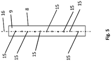
- Fig. 5 shows an alternative embodiment of the conveyor implemented as a conveyor belt 8.
- the conveyor belt 8a is narrower than that in FIG Fig. 4 shown conveyor belt 8 executed.
- the drivers 15 are arranged in alignment one behind the other. This embodiment of the conveying means limits the entrainment of the stick-shaped piece goods to a single element in the area of the respective driver 15.
- the chute 13 has two or, in the case of the conveyor belt 8a, only one channel 14.
Landscapes
- Engineering & Computer Science (AREA)
- Mechanical Engineering (AREA)
- Attitude Control For Articles On Conveyors (AREA)
- Discharge Of Articles From Conveyors (AREA)
Claims (15)
- Dispositif (1) de séparation et d'orientation de pièces en forme de broche présentant une tête et une tige, en particulier de rivets, comprenant :- un récipient (2) ayant sensiblement la forme d'un entonnoir pour recevoir les pièces, comportant deux sections de paroi (3, 4) qui délimitent le récipient (2) dans une zone avant, et une paroi arrière (5), dans lequel les sections de paroi (3, 4) et la paroi arrière (5) sont disposées par sections de manière opposée et de manière respectivement inclinée vers l'extérieur en formant un certain angle par rapport au plan transversal central (6) du récipient (2) ;- un moyen transporteur (8) tournant sans fin, disposé sous un évidement (7), en particulier en forme de fente, qui sépare les deux sections de paroi (3, 4), lequel est disposé de manière inclinée du même angle (α) que les sections de paroi (3, 4) par rapport au plan transversal central (6) et transporte les pièces depuis un plan de réception jusqu'à un plan de déchargement situé plus haut ;- dans lequel le moyen transporteur (8) présente un plan de transport (9) muni d'organes d'entraînement (15) ;caractérisé- en ce que l'évidement (7) est délimité par des bords avant (10, 11), parallèles entre eux, des sections de paroi (3, 4), lesquelles sont disposées en forme de V et s'étendent vers le moyen transporteur (8) et s'ouvrent au-dessus du moyen transporteur (8) ou dans un plan formé avec le moyen transporteur (8), et- en ce que les organes d'entraînement (15) sont réalisés sous la forme de broches cylindriques qui sont disposées à distance les unes des autres dans le sens de rotation du moyen transporteur (8) et qui s'étendent sensiblement perpendiculairement au plan de transport (9) du moyen transporteur (8).
- Dispositif (1) selon la revendication 1, caractérisé en ce que l'évidement (7) présente entre les sections de paroi (3, 4) une largeur (B) qui correspond au moins à la largeur des organes d'entraînement (15) et au plus à la longueur des pièces.
- Dispositif (1) selon l'une des revendications 1 ou 2, caractérisé en ce que les organes d'entraînement (15) présentent une section transversale circulaire ou polygonale.
- Dispositif (1) selon l'une des revendications 1 à 3, caractérisé en ce que les organes d'entraînement (15) sont disposés de manière décalée alternativement dans le sens de rotation du moyen transporteur (8) par rapport à l'axe longitudinal (16) du moyen transporteur (8), entre sa zone de bord et l'axe longitudinal (16).
- Dispositif (1) selon l'une des revendications 1 à 4, caractérisé en ce que les pièces transportées du moyen transporteur (8) au plan de déchargement sont transférées à un glissoir (13) disposé en aval et incliné par rapport à l'horizontale, qui présente au moins un conduit (14) ayant un profil sensiblement en forme de U, dans lequel la section transversale du conduit (14) est plus large que la tête et plus étroite que la longueur de la tige.
- Dispositif (1) selon les revendications 1 à 5, caractérisé en ce que l'inclinaison du moyen transporteur (8) est supérieure ou égale à 30° et inférieure ou égale à 60°.
- Dispositif (1) selon l'une des revendications 1 à 6, caractérisé en ce que l'évidement (7) s'étend sensiblement du point le plus bas du récipient (2) jusqu'au bord supérieur des sections de paroi (3, 4).
- Dispositif (1) selon l'une des revendications 5 à 7, caractérisé en ce que ladite au moins un conduit (14) présente un revêtement qui minimise l'adhérence.
- Dispositif (1) selon l'une des revendications 1 à 8, caractérisé en ce qu'un dispositif de détection (22), qui est conçu pour détecter des propriétés géométriques des pièces, est disposé dans le plan de déchargement ou à la hauteur du plan de déchargement ou en aval du plan de déchargement.
- Dispositif (1) selon l'une des revendications 1 à 9, caractérisé en ce que le moyen transporteur (8) peut être entraîné de manière électromécanique par un actionneur.
- Dispositif (1) selon l'une des revendications 1 à 9, caractérisé en ce que le moyen transporteur (8) peut être entraîné de manière mécanique ou pneumatique.
- Dispositif (1) selon l'une des revendications 5 à 11, caractérisé en ce qu'en aval du glissoir (13) est disposé un dispositif transporteur (17) qui transporte les pièces provenant du glissoir (13) à une vitesse de transport qui dépend de la vitesse d'entraînement du moyen transporteur (8) disposé dans le récipient (2).
- Dispositif (1) selon l'une des revendications 1 à 12, caractérisé en ce que le moyen transporteur est réalisé sous la forme d'une bande transporteuse (8) ou d'une chaîne à maillons.
- Dispositif (1) selon la revendication 12 ou 13, caractérisé en ce que le dispositif transporteur (17) est couplé de manière entraînée au moyen transporteur (8).
- Dispositif (1) selon l'une des revendications 12 à 14, caractérisé en ce qu'il est prévu au moins un élément de séparation (20) permettant de diviser une surface de transport du dispositif transporteur (17) en deux sections de transport parallèles et espacées l'une de l'autre, qui sont adaptées à la distance existant entre deux conduits (14) dans la zone de déchargement.
Priority Applications (1)
| Application Number | Priority Date | Filing Date | Title |
|---|---|---|---|
| PL18020627T PL3501689T3 (pl) | 2017-12-19 | 2018-12-04 | Urządzenie do rozdzielania i ustawiania elementów drobnych w kształcie trzpienia |
Applications Claiming Priority (1)
| Application Number | Priority Date | Filing Date | Title |
|---|---|---|---|
| DE102017130500.9A DE102017130500A1 (de) | 2017-12-19 | 2017-12-19 | Vorrichtung zum Vereinzeln und Ausrichten von stiftförmigem Stückgut |
Publications (2)
| Publication Number | Publication Date |
|---|---|
| EP3501689A1 EP3501689A1 (fr) | 2019-06-26 |
| EP3501689B1 true EP3501689B1 (fr) | 2020-10-07 |
Family
ID=64650092
Family Applications (1)
| Application Number | Title | Priority Date | Filing Date |
|---|---|---|---|
| EP18020627.8A Active EP3501689B1 (fr) | 2017-12-19 | 2018-12-04 | Dispositif de séparation et d'orientation de pièces en forme de tige |
Country Status (6)
| Country | Link |
|---|---|
| US (1) | US10336554B1 (fr) |
| EP (1) | EP3501689B1 (fr) |
| CN (1) | CN109928171B (fr) |
| DE (1) | DE102017130500A1 (fr) |
| DK (1) | DK3501689T3 (fr) |
| PL (1) | PL3501689T3 (fr) |
Families Citing this family (3)
| Publication number | Priority date | Publication date | Assignee | Title |
|---|---|---|---|---|
| FR3096598B1 (fr) * | 2019-05-29 | 2021-07-16 | Novares France | Dispositif de distribution de composants de type agrafe |
| CN111071754A (zh) * | 2019-12-31 | 2020-04-28 | 上汽通用五菱汽车股份有限公司 | 一种气门座圈自动上料装置 |
| DE102020131870A1 (de) * | 2020-12-01 | 2022-06-02 | Weber Schraubautomaten Gesellschaft mit beschränkter Haftung | Fördereinheit |
Family Cites Families (24)
| Publication number | Priority date | Publication date | Assignee | Title |
|---|---|---|---|---|
| FR1430899A (fr) * | 1964-09-10 | 1966-03-11 | Tuboplast France | Machine pour la fabrication en continu de corps creux |
| US3272118A (en) * | 1965-02-04 | 1966-09-13 | Hartnett Co R W | Article marking machine |
| DE2309923C2 (de) * | 1973-02-28 | 1983-10-20 | Costruzioni Meccaniche Tessili San Grato P. Nicolo & Co. S.a.s., Sordevolo, Vercelli | Maschine zur automatischen Einbringung von kegelstumpfförmigen Garnhülsen in Behälter |
| CH630306A5 (de) * | 1978-07-21 | 1982-06-15 | Sig Schweiz Industrieges | Einrichtung zum einfuellen von plaettchenfoermigen stuecken in behaelter. |
| AU553413B2 (en) * | 1982-02-18 | 1986-07-17 | Kureha Kagaku Kogyo K.K. | Heating parisons for blow moulding |
| DE4039678A1 (de) * | 1990-12-12 | 1992-06-17 | Marco Bachmann | Vorrichtung zur foerderung von in einem vorratsbehaelter enthaltener ware in eine vorgegebene richtung |
| GB2252964A (en) * | 1991-02-25 | 1992-08-26 | Tienchi Trading Co Ltd | Delivery of fastening elements such as screws |
| US5376771A (en) * | 1992-07-07 | 1994-12-27 | Merck & Co., Inc. | High speed process for preparing orifices in pharmaceutical dosage forms |
| DE19530771B4 (de) * | 1995-08-22 | 2004-05-19 | WINKLER + DüNNEBIER AG | Streuvorrichtung zum dosierten Auftragen |
| US6185901B1 (en) * | 1998-05-20 | 2001-02-13 | Aylward Enterprises, Inc. | Positive count rotary slat packaging apparatus and related methods |
| US6568151B2 (en) * | 2001-02-07 | 2003-05-27 | Kalish, Inc. | Conveyor for use in contamination sensitive equipment |
| US6622849B1 (en) * | 2002-09-26 | 2003-09-23 | Sperling Railway Services, Inc. | Hopper door assembly and method for feeding bulk metal objects from a hopper |
| US20040094389A1 (en) * | 2002-11-19 | 2004-05-20 | Boyce Keith W. | Conveyor having carriers with movable jaws |
| ES2223247B1 (es) * | 2002-11-22 | 2006-04-16 | Tomas Mulet Valles | Maquina alimentadora-dispensadora de recipientes y articulos alargados en general. |
| CH698447B1 (de) | 2005-12-14 | 2009-08-14 | Bosch Gmbh Robert | Vorrichtung zum Ausrichten und Zuführen von Vorformlingen. |
| JP5676103B2 (ja) * | 2006-08-22 | 2015-02-25 | イー・マイケル・アクレイ・ジュニア | オンエッジ錠剤の搬送及び加工方法及び装置 |
| US7795556B1 (en) * | 2006-09-14 | 2010-09-14 | Dean Edward T | Packaging apparatus |
| US8616364B2 (en) * | 2011-10-11 | 2013-12-31 | Cnh America Llc | Harvester crop delivery system |
| CN202447577U (zh) * | 2012-02-04 | 2012-09-26 | 杭州彼特环保包装有限公司 | 一种铆钉出料导轨的分离装置 |
| US9096390B2 (en) * | 2013-09-20 | 2015-08-04 | Ackley Machine Corporation | Apparatus and method for inspecting and processing pellet-shaped articles |
| CN104668427B (zh) * | 2014-12-31 | 2017-01-25 | 大连运明自动化技术有限公司 | 高速智能化铆钉分钉供钉装置 |
| US10370135B2 (en) * | 2015-02-10 | 2019-08-06 | 3605329 Canada Inc. | Belt sorting system |
| CN105499471B (zh) * | 2016-02-22 | 2018-01-19 | 三峡大学 | 一种铆接生产线铆钉的上料装置和上料方法 |
| US10124968B2 (en) * | 2016-04-29 | 2018-11-13 | The Babcock & Wilcox Company | Simplified submerged chain conveyor for bottom ash conversions |
-
2017
- 2017-12-19 DE DE102017130500.9A patent/DE102017130500A1/de not_active Withdrawn
-
2018
- 2018-12-04 PL PL18020627T patent/PL3501689T3/pl unknown
- 2018-12-04 EP EP18020627.8A patent/EP3501689B1/fr active Active
- 2018-12-04 DK DK18020627.8T patent/DK3501689T3/da active
- 2018-12-18 US US16/223,649 patent/US10336554B1/en active Active
- 2018-12-19 CN CN201811556243.8A patent/CN109928171B/zh active Active
Non-Patent Citations (1)
| Title |
|---|
| None * |
Also Published As
| Publication number | Publication date |
|---|---|
| US20190185274A1 (en) | 2019-06-20 |
| PL3501689T3 (pl) | 2021-02-08 |
| US10336554B1 (en) | 2019-07-02 |
| CN109928171A (zh) | 2019-06-25 |
| CN109928171B (zh) | 2021-11-12 |
| EP3501689A1 (fr) | 2019-06-26 |
| DE102017130500A1 (de) | 2019-06-19 |
| DK3501689T3 (da) | 2020-12-21 |
Similar Documents
| Publication | Publication Date | Title |
|---|---|---|
| EP3501689B1 (fr) | Dispositif de séparation et d'orientation de pièces en forme de tige | |
| EP2346757B1 (fr) | Dispositif de séparation et de positionnement de fermetures métalliques de contenant | |
| EP1694589B1 (fr) | Dispositif de separation pour pieces allongees et dispositif de transport desdites pieces | |
| EP3725714A1 (fr) | Dispositif de stockage pour une matière en vrac, en particulier copeaux de bois, et procédé de remplissage | |
| WO2003018215A1 (fr) | Dispositif pour trier des envois par categories d'epaisseurs | |
| EP3162739B1 (fr) | Dispositif et procede de transfert de portions de saucisses | |
| EP0718219A2 (fr) | Dispositif pour individualiser des objets | |
| EP3053859B1 (fr) | Dispositif de separation et d'alignement de moyen de fixation | |
| WO2005105471A1 (fr) | Dispositif d'acheminement et dispositif de liaison | |
| EP3680032A1 (fr) | Dispositif de tri | |
| EP3469911B1 (fr) | Dispositif de transport de saucisse oblongue comportant une courbure | |
| DE10148226C1 (de) | Vorrichtung zum Trennen von flachen Sendungen in Dickenklassen | |
| AT391842B (de) | Vorrichtung zum zufuehren und vereinzeln von montageteilen | |
| EP3527510A1 (fr) | Dispositif de séparation destiné à séparer des crochets croisés | |
| EP2660169A1 (fr) | Convoyeur linéaire et procédé d'acheminement pour des éléments de liaison | |
| EP4269288A2 (fr) | Dispositif de transport et procédé de transport d'applicateurs de tampon | |
| DE102018116357A1 (de) | Vorrichtung zum Vereinzeln und Ausrichten von stiftförmigem Stückgut | |
| DE202005019112U1 (de) | Einrichtung zur Vereinzelung von gefrorenem Stückgut | |
| DE3321173C2 (fr) | ||
| DE4214428C2 (de) | Vorrichtung und Verfahren zur Trennung magnetisierbarer und unmagnetisierbarer Bestandteile eines Gemisches voneinander und Aufgabe-Gerät hierfür | |
| AT393256B (de) | Einrichtung zur orientierung von stueckerzeugnissen in zufuehrungseinheiten von aggregaten | |
| DE19841860A1 (de) | Vorrichtung zum Sortieren und/oder Zählen von unterschiedlichen Münzen | |
| DE645094C (de) | Vorrichtung zum Zufuehren von Naegeln, Reissbrettstiften und aehnlichen Gegenstaenden zu Arbeitsstellen von einem Vorratsbehaelter aus mittels eines mit Mitnehmern versehenen endlosen Foerderbandes | |
| EP3506219B1 (fr) | Dispositif et procédé destinés à la séparation et au transport forcé d'objets en forme de disque, en particulier de pièces | |
| DE3048231A1 (de) | Vorrichtung zum transport, ausrichten und aneinanderreihen von runden laenglichen gegenstaenden |
Legal Events
| Date | Code | Title | Description |
|---|---|---|---|
| PUAI | Public reference made under article 153(3) epc to a published international application that has entered the european phase |
Free format text: ORIGINAL CODE: 0009012 |
|
| STAA | Information on the status of an ep patent application or granted ep patent |
Free format text: STATUS: THE APPLICATION HAS BEEN PUBLISHED |
|
| AK | Designated contracting states |
Kind code of ref document: A1 Designated state(s): AL AT BE BG CH CY CZ DE DK EE ES FI FR GB GR HR HU IE IS IT LI LT LU LV MC MK MT NL NO PL PT RO RS SE SI SK SM TR |
|
| AX | Request for extension of the european patent |
Extension state: BA ME |
|
| STAA | Information on the status of an ep patent application or granted ep patent |
Free format text: STATUS: REQUEST FOR EXAMINATION WAS MADE |
|
| 17P | Request for examination filed |
Effective date: 20191218 |
|
| RBV | Designated contracting states (corrected) |
Designated state(s): AL AT BE BG CH CY CZ DE DK EE ES FI FR GB GR HR HU IE IS IT LI LT LU LV MC MK MT NL NO PL PT RO RS SE SI SK SM TR |
|
| GRAP | Despatch of communication of intention to grant a patent |
Free format text: ORIGINAL CODE: EPIDOSNIGR1 |
|
| STAA | Information on the status of an ep patent application or granted ep patent |
Free format text: STATUS: GRANT OF PATENT IS INTENDED |
|
| INTG | Intention to grant announced |
Effective date: 20200422 |
|
| GRAS | Grant fee paid |
Free format text: ORIGINAL CODE: EPIDOSNIGR3 |
|
| GRAA | (expected) grant |
Free format text: ORIGINAL CODE: 0009210 |
|
| STAA | Information on the status of an ep patent application or granted ep patent |
Free format text: STATUS: THE PATENT HAS BEEN GRANTED |
|
| AK | Designated contracting states |
Kind code of ref document: B1 Designated state(s): AL AT BE BG CH CY CZ DE DK EE ES FI FR GB GR HR HU IE IS IT LI LT LU LV MC MK MT NL NO PL PT RO RS SE SI SK SM TR |
|
| REG | Reference to a national code |
Ref country code: GB Ref legal event code: FG4D Free format text: NOT ENGLISH |
|
| REG | Reference to a national code |
Ref country code: CH Ref legal event code: EP Ref country code: AT Ref legal event code: REF Ref document number: 1320598 Country of ref document: AT Kind code of ref document: T Effective date: 20201015 |
|
| REG | Reference to a national code |
Ref country code: IE Ref legal event code: FG4D Free format text: LANGUAGE OF EP DOCUMENT: GERMAN |
|
| REG | Reference to a national code |
Ref country code: DE Ref legal event code: R096 Ref document number: 502018002632 Country of ref document: DE |
|
| REG | Reference to a national code |
Ref country code: DK Ref legal event code: T3 Effective date: 20201217 |
|
| REG | Reference to a national code |
Ref country code: NL Ref legal event code: FP |
|
| PG25 | Lapsed in a contracting state [announced via postgrant information from national office to epo] |
Ref country code: NO Free format text: LAPSE BECAUSE OF FAILURE TO SUBMIT A TRANSLATION OF THE DESCRIPTION OR TO PAY THE FEE WITHIN THE PRESCRIBED TIME-LIMIT Effective date: 20210107 Ref country code: GR Free format text: LAPSE BECAUSE OF FAILURE TO SUBMIT A TRANSLATION OF THE DESCRIPTION OR TO PAY THE FEE WITHIN THE PRESCRIBED TIME-LIMIT Effective date: 20210108 Ref country code: FI Free format text: LAPSE BECAUSE OF FAILURE TO SUBMIT A TRANSLATION OF THE DESCRIPTION OR TO PAY THE FEE WITHIN THE PRESCRIBED TIME-LIMIT Effective date: 20201007 Ref country code: PT Free format text: LAPSE BECAUSE OF FAILURE TO SUBMIT A TRANSLATION OF THE DESCRIPTION OR TO PAY THE FEE WITHIN THE PRESCRIBED TIME-LIMIT Effective date: 20210208 Ref country code: RS Free format text: LAPSE BECAUSE OF FAILURE TO SUBMIT A TRANSLATION OF THE DESCRIPTION OR TO PAY THE FEE WITHIN THE PRESCRIBED TIME-LIMIT Effective date: 20201007 |
|
| REG | Reference to a national code |
Ref country code: LT Ref legal event code: MG4D |
|
| PG25 | Lapsed in a contracting state [announced via postgrant information from national office to epo] |
Ref country code: ES Free format text: LAPSE BECAUSE OF FAILURE TO SUBMIT A TRANSLATION OF THE DESCRIPTION OR TO PAY THE FEE WITHIN THE PRESCRIBED TIME-LIMIT Effective date: 20201007 Ref country code: LV Free format text: LAPSE BECAUSE OF FAILURE TO SUBMIT A TRANSLATION OF THE DESCRIPTION OR TO PAY THE FEE WITHIN THE PRESCRIBED TIME-LIMIT Effective date: 20201007 Ref country code: IS Free format text: LAPSE BECAUSE OF FAILURE TO SUBMIT A TRANSLATION OF THE DESCRIPTION OR TO PAY THE FEE WITHIN THE PRESCRIBED TIME-LIMIT Effective date: 20210207 Ref country code: SE Free format text: LAPSE BECAUSE OF FAILURE TO SUBMIT A TRANSLATION OF THE DESCRIPTION OR TO PAY THE FEE WITHIN THE PRESCRIBED TIME-LIMIT Effective date: 20201007 Ref country code: BG Free format text: LAPSE BECAUSE OF FAILURE TO SUBMIT A TRANSLATION OF THE DESCRIPTION OR TO PAY THE FEE WITHIN THE PRESCRIBED TIME-LIMIT Effective date: 20210107 |
|
| PG25 | Lapsed in a contracting state [announced via postgrant information from national office to epo] |
Ref country code: HR Free format text: LAPSE BECAUSE OF FAILURE TO SUBMIT A TRANSLATION OF THE DESCRIPTION OR TO PAY THE FEE WITHIN THE PRESCRIBED TIME-LIMIT Effective date: 20201007 |
|
| REG | Reference to a national code |
Ref country code: DE Ref legal event code: R097 Ref document number: 502018002632 Country of ref document: DE |
|
| PG25 | Lapsed in a contracting state [announced via postgrant information from national office to epo] |
Ref country code: RO Free format text: LAPSE BECAUSE OF FAILURE TO SUBMIT A TRANSLATION OF THE DESCRIPTION OR TO PAY THE FEE WITHIN THE PRESCRIBED TIME-LIMIT Effective date: 20201007 Ref country code: SK Free format text: LAPSE BECAUSE OF FAILURE TO SUBMIT A TRANSLATION OF THE DESCRIPTION OR TO PAY THE FEE WITHIN THE PRESCRIBED TIME-LIMIT Effective date: 20201007 Ref country code: EE Free format text: LAPSE BECAUSE OF FAILURE TO SUBMIT A TRANSLATION OF THE DESCRIPTION OR TO PAY THE FEE WITHIN THE PRESCRIBED TIME-LIMIT Effective date: 20201007 Ref country code: CZ Free format text: LAPSE BECAUSE OF FAILURE TO SUBMIT A TRANSLATION OF THE DESCRIPTION OR TO PAY THE FEE WITHIN THE PRESCRIBED TIME-LIMIT Effective date: 20201007 Ref country code: LT Free format text: LAPSE BECAUSE OF FAILURE TO SUBMIT A TRANSLATION OF THE DESCRIPTION OR TO PAY THE FEE WITHIN THE PRESCRIBED TIME-LIMIT Effective date: 20201007 Ref country code: SM Free format text: LAPSE BECAUSE OF FAILURE TO SUBMIT A TRANSLATION OF THE DESCRIPTION OR TO PAY THE FEE WITHIN THE PRESCRIBED TIME-LIMIT Effective date: 20201007 |
|
| PLBE | No opposition filed within time limit |
Free format text: ORIGINAL CODE: 0009261 |
|
| STAA | Information on the status of an ep patent application or granted ep patent |
Free format text: STATUS: NO OPPOSITION FILED WITHIN TIME LIMIT |
|
| PG25 | Lapsed in a contracting state [announced via postgrant information from national office to epo] |
Ref country code: MC Free format text: LAPSE BECAUSE OF FAILURE TO SUBMIT A TRANSLATION OF THE DESCRIPTION OR TO PAY THE FEE WITHIN THE PRESCRIBED TIME-LIMIT Effective date: 20201007 |
|
| 26N | No opposition filed |
Effective date: 20210708 |
|
| PG25 | Lapsed in a contracting state [announced via postgrant information from national office to epo] |
Ref country code: LU Free format text: LAPSE BECAUSE OF NON-PAYMENT OF DUE FEES Effective date: 20201204 Ref country code: AL Free format text: LAPSE BECAUSE OF FAILURE TO SUBMIT A TRANSLATION OF THE DESCRIPTION OR TO PAY THE FEE WITHIN THE PRESCRIBED TIME-LIMIT Effective date: 20201007 Ref country code: IE Free format text: LAPSE BECAUSE OF NON-PAYMENT OF DUE FEES Effective date: 20201204 |
|
| PG25 | Lapsed in a contracting state [announced via postgrant information from national office to epo] |
Ref country code: SI Free format text: LAPSE BECAUSE OF FAILURE TO SUBMIT A TRANSLATION OF THE DESCRIPTION OR TO PAY THE FEE WITHIN THE PRESCRIBED TIME-LIMIT Effective date: 20201007 |
|
| PG25 | Lapsed in a contracting state [announced via postgrant information from national office to epo] |
Ref country code: IS Free format text: LAPSE BECAUSE OF FAILURE TO SUBMIT A TRANSLATION OF THE DESCRIPTION OR TO PAY THE FEE WITHIN THE PRESCRIBED TIME-LIMIT Effective date: 20210207 Ref country code: TR Free format text: LAPSE BECAUSE OF FAILURE TO SUBMIT A TRANSLATION OF THE DESCRIPTION OR TO PAY THE FEE WITHIN THE PRESCRIBED TIME-LIMIT Effective date: 20201007 Ref country code: MT Free format text: LAPSE BECAUSE OF FAILURE TO SUBMIT A TRANSLATION OF THE DESCRIPTION OR TO PAY THE FEE WITHIN THE PRESCRIBED TIME-LIMIT Effective date: 20201007 Ref country code: CY Free format text: LAPSE BECAUSE OF FAILURE TO SUBMIT A TRANSLATION OF THE DESCRIPTION OR TO PAY THE FEE WITHIN THE PRESCRIBED TIME-LIMIT Effective date: 20201007 |
|
| PG25 | Lapsed in a contracting state [announced via postgrant information from national office to epo] |
Ref country code: MK Free format text: LAPSE BECAUSE OF FAILURE TO SUBMIT A TRANSLATION OF THE DESCRIPTION OR TO PAY THE FEE WITHIN THE PRESCRIBED TIME-LIMIT Effective date: 20201007 |
|
| PGFP | Annual fee paid to national office [announced via postgrant information from national office to epo] |
Ref country code: NL Payment date: 20221222 Year of fee payment: 5 Ref country code: GB Payment date: 20221222 Year of fee payment: 5 Ref country code: FR Payment date: 20221222 Year of fee payment: 5 Ref country code: DK Payment date: 20221223 Year of fee payment: 5 |
|
| PGFP | Annual fee paid to national office [announced via postgrant information from national office to epo] |
Ref country code: PL Payment date: 20221128 Year of fee payment: 5 Ref country code: BE Payment date: 20221221 Year of fee payment: 5 |
|
| PGFP | Annual fee paid to national office [announced via postgrant information from national office to epo] |
Ref country code: CH Payment date: 20221213 Year of fee payment: 5 |
|
| PGFP | Annual fee paid to national office [announced via postgrant information from national office to epo] |
Ref country code: IT Payment date: 20221228 Year of fee payment: 5 |
|
| PGFP | Annual fee paid to national office [announced via postgrant information from national office to epo] |
Ref country code: DE Payment date: 20240226 Year of fee payment: 6 |