EP2346757B1 - Dispositif de séparation et de positionnement de fermetures métalliques de contenant - Google Patents
Dispositif de séparation et de positionnement de fermetures métalliques de contenant Download PDFInfo
- Publication number
- EP2346757B1 EP2346757B1 EP09744656.1A EP09744656A EP2346757B1 EP 2346757 B1 EP2346757 B1 EP 2346757B1 EP 09744656 A EP09744656 A EP 09744656A EP 2346757 B1 EP2346757 B1 EP 2346757B1
- Authority
- EP
- European Patent Office
- Prior art keywords
- transfer station
- container closures
- conveyor
- conveying
- section
- Prior art date
- Legal status (The legal status is an assumption and is not a legal conclusion. Google has not performed a legal analysis and makes no representation as to the accuracy of the status listed.)
- Active
Links
- 239000002184 metal Substances 0.000 title 1
- 238000012546 transfer Methods 0.000 claims description 171
- 239000004033 plastic Substances 0.000 claims description 18
- 229920003023 plastic Polymers 0.000 claims description 18
- 230000005484 gravity Effects 0.000 claims description 15
- XEEYBQQBJWHFJM-UHFFFAOYSA-N Iron Chemical compound [Fe] XEEYBQQBJWHFJM-UHFFFAOYSA-N 0.000 claims description 13
- 238000000926 separation method Methods 0.000 claims description 12
- 230000032258 transport Effects 0.000 claims description 12
- 239000013590 bulk material Substances 0.000 claims description 11
- 230000007704 transition Effects 0.000 claims description 11
- 238000012545 processing Methods 0.000 claims description 10
- 239000004698 Polyethylene Substances 0.000 claims description 6
- 229910052742 iron Inorganic materials 0.000 claims description 6
- 229920000573 polyethylene Polymers 0.000 claims description 6
- -1 polyethylene Polymers 0.000 claims description 5
- 229910000831 Steel Inorganic materials 0.000 claims description 3
- 239000004809 Teflon Substances 0.000 claims description 3
- 229920006362 Teflon® Polymers 0.000 claims description 3
- 239000002253 acid Substances 0.000 claims description 3
- 239000010959 steel Substances 0.000 claims description 3
- 238000005260 corrosion Methods 0.000 claims description 2
- 230000007797 corrosion Effects 0.000 claims description 2
- 238000007789 sealing Methods 0.000 claims description 2
- 239000011248 coating agent Substances 0.000 claims 1
- 238000000576 coating method Methods 0.000 claims 1
- 239000007799 cork Substances 0.000 description 33
- 238000012384 transportation and delivery Methods 0.000 description 8
- 238000009826 distribution Methods 0.000 description 7
- 230000008901 benefit Effects 0.000 description 5
- 238000007664 blowing Methods 0.000 description 4
- 238000003860 storage Methods 0.000 description 4
- 230000015572 biosynthetic process Effects 0.000 description 3
- 230000008859 change Effects 0.000 description 3
- 238000005299 abrasion Methods 0.000 description 2
- 238000013459 approach Methods 0.000 description 2
- 239000000428 dust Substances 0.000 description 2
- 230000000694 effects Effects 0.000 description 2
- 238000000605 extraction Methods 0.000 description 2
- 238000012423 maintenance Methods 0.000 description 2
- 238000000034 method Methods 0.000 description 2
- 230000008569 process Effects 0.000 description 2
- 230000009467 reduction Effects 0.000 description 2
- 239000000853 adhesive Substances 0.000 description 1
- 230000001070 adhesive effect Effects 0.000 description 1
- 238000005452 bending Methods 0.000 description 1
- 230000005540 biological transmission Effects 0.000 description 1
- 230000009194 climbing Effects 0.000 description 1
- 238000010276 construction Methods 0.000 description 1
- 238000011109 contamination Methods 0.000 description 1
- 230000002950 deficient Effects 0.000 description 1
- 238000013461 design Methods 0.000 description 1
- 238000007598 dipping method Methods 0.000 description 1
- 230000001771 impaired effect Effects 0.000 description 1
- 230000006872 improvement Effects 0.000 description 1
- 230000002452 interceptive effect Effects 0.000 description 1
- 230000005415 magnetization Effects 0.000 description 1
- 238000007726 management method Methods 0.000 description 1
- 238000004519 manufacturing process Methods 0.000 description 1
- NJPPVKZQTLUDBO-UHFFFAOYSA-N novaluron Chemical compound C1=C(Cl)C(OC(F)(F)C(OC(F)(F)F)F)=CC=C1NC(=O)NC(=O)C1=C(F)C=CC=C1F NJPPVKZQTLUDBO-UHFFFAOYSA-N 0.000 description 1
- 230000000149 penetrating effect Effects 0.000 description 1
- 230000008439 repair process Effects 0.000 description 1
- 230000000284 resting effect Effects 0.000 description 1
- 238000006748 scratching Methods 0.000 description 1
- 230000002393 scratching effect Effects 0.000 description 1
- 229910001220 stainless steel Inorganic materials 0.000 description 1
- 239000010935 stainless steel Substances 0.000 description 1
- 238000012549 training Methods 0.000 description 1
- 238000013024 troubleshooting Methods 0.000 description 1
- 238000011144 upstream manufacturing Methods 0.000 description 1
Images


Classifications
-
- B—PERFORMING OPERATIONS; TRANSPORTING
- B65—CONVEYING; PACKING; STORING; HANDLING THIN OR FILAMENTARY MATERIAL
- B65G—TRANSPORT OR STORAGE DEVICES, e.g. CONVEYORS FOR LOADING OR TIPPING, SHOP CONVEYOR SYSTEMS OR PNEUMATIC TUBE CONVEYORS
- B65G47/00—Article or material-handling devices associated with conveyors; Methods employing such devices
- B65G47/02—Devices for feeding articles or materials to conveyors
- B65G47/04—Devices for feeding articles or materials to conveyors for feeding articles
- B65G47/12—Devices for feeding articles or materials to conveyors for feeding articles from disorderly-arranged article piles or from loose assemblages of articles
- B65G47/14—Devices for feeding articles or materials to conveyors for feeding articles from disorderly-arranged article piles or from loose assemblages of articles arranging or orientating the articles by mechanical or pneumatic means during feeding
- B65G47/1407—Devices for feeding articles or materials to conveyors for feeding articles from disorderly-arranged article piles or from loose assemblages of articles arranging or orientating the articles by mechanical or pneumatic means during feeding the articles being fed from a container, e.g. a bowl
- B65G47/1442—Devices for feeding articles or materials to conveyors for feeding articles from disorderly-arranged article piles or from loose assemblages of articles arranging or orientating the articles by mechanical or pneumatic means during feeding the articles being fed from a container, e.g. a bowl by means of movement of the bottom or a part of the wall of the container
- B65G47/1471—Movement in one direction, substantially outwards
-
- B—PERFORMING OPERATIONS; TRANSPORTING
- B67—OPENING, CLOSING OR CLEANING BOTTLES, JARS OR SIMILAR CONTAINERS; LIQUID HANDLING
- B67B—APPLYING CLOSURE MEMBERS TO BOTTLES JARS, OR SIMILAR CONTAINERS; OPENING CLOSED CONTAINERS
- B67B3/00—Closing bottles, jars or similar containers by applying caps
- B67B3/02—Closing bottles, jars or similar containers by applying caps by applying flanged caps, e.g. crown caps, and securing by deformation of flanges
- B67B3/06—Feeding caps to capping heads
- B67B3/064—Feeding caps to capping heads from a hopper
- B67B3/0645—Feeding caps to capping heads from a hopper with means for orientating the caps to a position ready to be applied to the container
Definitions
- the present invention relates to a device for separating and position aligning metallic container closures and for conveying the isolated and position-aligned container closures, preferably crown corks, to a further processing machine, preferably closing machine, wherein the device comprises at least one reservoir for the container closures, and at least one removal conveyor for Removal and preorientation of the container closures from the at least one storage container, wherein the at least one removal conveyor in the operating position of the device has a steep conveyor section whose conveying surface with the contact plane an angle> 30 °, preferably> 80 ° includes, and at least one, the isolated and position-aligned container closures to the closing machine transporting conveyor unit, which the container closures by means of a support surface at each of a Refe contacting the container closures, and a transfer station, in which the container closures are blown transversely to the conveying direction of the at least one removal conveyor from the steep conveyor section and by means of which the container closures isolated and location-oriented transferred to the conveyor unit, wherein a arranged immediately
- Such devices are used in Be memorien used and serve the exact delivery of the container closures to a Closing machine which attaches the container closures to the containers to close them.
- FR 2 876 990 A1 is a generic device for sorting and separating of screw caps made of plastic, in which the carriage of the screw caps for closing machine is indeed carried out in a certain inaccessible without aids height, the transfer station, however, is arranged near the ground for the reasons mentioned above.
- a fan is provided, which conveys the container closures by means of air flow from the transfer station upwards.
- Such a device is not suitable for separating and position alignment of metallic container closures, in particular crown corks, since these are too heavy for transport by means of air flow upwards.
- a device for separating and aligning position of metallic container closures and for conveying the isolated and position-aligned container closures, preferably crown corks, to a closing machine wherein the device comprises at least one reservoir and / or task unit for the container closures, and at least one removal conveyor for removal and Vororientierung the container closures from the at least one reservoir
- the at least one removal conveyor in the operating position of the device has a steep conveyor section, the conveying surface with the contact plane an angle> 30 °, preferably> 80 °, and at least one
- the isolated and position-aligned container closures for closing machine transporting conveyor unit which kontkont the container closures by means of a support surface on each of a reference surface of the container closures activated, as well as one Transfer station, in which the container closures are blown transversely to the conveying direction of the at least one removal conveyor from the steep conveyor section and by means of which the container closures are separated and transferred position-oriented to the conveyor unit and wherein an immediately after the transfer
- the removal conveyor is actually used almost exclusively to remove the container closures from the storage container and to preorient them, but is not used to transport the container closures over a considerable distance in the direction of the closing machine or around the container closures to a certain height to transport them in order to separate them at this height and handed over situation-oriented to the conveyor unit.
- transfer station is understood to be any type of section of the device in which a transfer of the unoriented or pre-oriented container closures to a delivery unit takes place, on which a further transport of the container closures takes place in an isolated and position-oriented orientation.
- a second conveyor section which extends substantially horizontally in the operating position of the device, is provided at the first conveyor section, the axis of curvature of the transition between the two conveyor sections being parallel to the support surface of the conveyor unit or to the reference surface of the transported on the conveyor unit container closures and the transition is preferably without pulleys and with a large radius.
- the largest possible surface area of the container closure is selected as a reference surface, for example, its back so that they adhere well to the magnetic conveyor unit and on the other hand is prevented due to the deflection "backwards" on this surface, that the container closures on the conveyor unit move, which on the one hand would lead to undesirable abrasion and on the other hand, the container closures also visually impaired, which would not be accepted by the end user.
- the preferably deflection roller-free transition between the first and second conveyor section of the conveyor unit allows on the one hand a particularly gentle deflection and on the other hand, a constant magnetic holding force in this deflection.
- the transfer station is arranged at a height measured from the contact plane of the device between 1m and 3m, preferably between 1m and 2m. So she is in an ideal height to be maintained or repaired without aids. Disturbances can thus, in contrast to known from the prior art, generic devices immediately be resolved by the operator without climbing pedestal or ladders. Also, the necessary for a possibly necessary repair or maintenance tool does not need to be raised to a height of 4m to 6m.
- the transfer station is arranged directly adjacent to the at least one removal conveyor and comprises a substantially parallel to the steep conveyor section of the removal conveyor arranged bottom and lid, wherein at least one feed opening is provided, via which the container closures from the removal conveyor can be transported to the transfer station.
- the distance between the bottom and lid of the transfer station allows the lateral loading of the transfer station with container closures of the at least one removal conveyor with respect to their reference surface only in that position in which transported the container closures in the removal conveyor become.
- the transfer station thus forms a positive guide for the container closures, so that they in the transfer station can be transferred without losing the preorientation that they have been forced by the withdrawal conveyor.
- a subsection of the at least one conveyor unit forms a section of the bottom of the transfer station, so that the container closures transported and preoriented by the at least one removal conveyor into the transfer station depend at least on the quantity and geometry of the transfer container Transfer station to come to lie randomly with their reference surface on the conveyor unit. Due to the fact that the delivery unit is formed magnetically, it can thus be ensured that the metallic container closures are transported by the conveyor unit from the transfer station, which influence by geometrical design of the transfer station and / or strength, size and arrangement or shape of the magnetic field the separation performance of the transfer station can be taken.
- the transfer point ie that predetermined area of the transfer station at which the container closures are necessarily taken by the conveyor unit necessarily, either as the lowest or highest point of a lower operating boundary of the device in the transfer station formed, which connects the bottom and lid of the transfer station together.
- the container closures conveyed from the removal conveyor via the loading opening into the transfer station fall in this way into the transfer station to the lowest point, in order then to be separated by means of the delivery unit and to be conveyed further in a line-aligned manner.
- the at least one removal conveyor is in a particularly preferred embodiment of the invention, preferably made of corrosion and / or acid-resistant steel, endless belt conveyor with a dipping into the reservoir flat conveyor section, the individual members seen in the conveying direction having a first end portion of a with a Chamfered driving element carries, and a second end portion, in which the members are vorzusglutter formed folded and the area between the driving element and the preferred Aufkantung for receiving the container closures in a row next to each other is provided.
- the production of the link belt conveyor made of corrosion- and / or acid-resistant steel has the advantage that it does not statically charge and is very resistant to wear, which is particularly important for crown caps as container closures, as they act on the crown very abrasive.
- the area between entrainment element and upstand can be adapted in a simple manner to the size of the container closures.
- the shape of the entrainment element is ideally matched to the shape of the container closure. The reduction in the inclination of the flat conveyor section relative to the steep conveyor section allows the increase in the occupancy of the extraction conveyor.
- At least one blow-out opening controlled by a blower unit is arranged in order to convey the container closures from the at least one removal conveyor in rows to the transfer station. It can be transported either row by row individually in the transfer station or several rows simultaneously.
- an additional air guide element can be provided, which is parallel to the cover, preferably integral part of the cover, both at least a portion of the steep conveyor section and at least a portion of the transfer station is arranged overlapping and directed into the transfer station and / or on the steep section of a blower unit controlled openings / slots, in order to convey the container closures on the one hand from the steep conveyor section in rows in the transfer station and on the other hand to convey already located in the transfer station container closures in the direction of transfer point.
- the additional air guide proves to be advantageous, since in this case additional amounts of air are required to carry the container closures against gravity to the higher transfer point.
- the conveying speed of the at least one conveying unit is a multiple of the conveying speed of the at least one removal conveyor. Since a plurality of container closures always conveys into the transfer station by the blow-out process of the at least one removal conveyor, it is provided according to the invention to operate the at least one conveyor unit at a higher conveying speed in order to avoid a jam of the container closures in the transfer station.
- the width of the run of the conveyor belt of the at least one conveyor unit is less than or equal to the greatest width of the container closures.
- the width of the run of the conveyor belt of the at least one conveyor unit is less than or equal to the greatest width of the container closures.
- the steep conveyor section of the removal conveyor, bottom and lid of the transfer station and the first conveyor section of the conveyor unit are arranged to extend vertically. Such an arrangement allows a particularly space-saving embodiment variant with respect to the contact plane of the device according to the invention.
- a magnet system may be arranged on the side of the at least one removal conveyor which is remote from the entrainment elements of the inclined conveying section, in order to bind the container closures more strongly to the removal conveyor in this area and to avoid deadlocks due to falling.
- two extraction conveyors extending parallel to one another are arranged and the transfer station and a conveyor unit transporting the separated and position-aligned container closures to the closing machine are arranged between the removal conveyors, wherein the transfer station has two charging openings.
- Such a device according to the invention has proved to be particularly efficient, since the Transfer station can be loaded on both sides and the delivery speeds of the removal conveyor and the conveyor unit can be optimally matched, in which the conveying speed of the conveyor units are selected slower to allow the scooping the container closures from the reservoir with optimum efficiency and on the other hand, the conveying speed of the conveyor unit easily can be increased so that the transported from the removal conveyors in the transfer station container closures easily separated from the conveyor unit and position-aligned from the transfer station and can be transported.
- a preferred embodiment provides that the relative position of the two removal conveyors to one another during conveyance is constant and either the entrainment elements on the individual links are always positioned differently with respect to their vertical distance from the contact plane of the device, or both Feed openings have a different vertical distance to the contact plane of the device. This ensures that the feed of the transfer station is always filled with a time delay from the two removal conveyors.
- a further preferred embodiment provides that the lower boundary wall of the transfer station is V-shaped, wherein each leg connects in each case the lowest point of a feed opening with the lowest point of the transfer station with respect to the contact plane.
- the container closures can thus fall from both sides in the transfer station and are automatically directed to the centrally located conveyor unit.
- a task unit is provided between the two removal conveyors and in the operating position of the device below the transfer station, which has a preferably wedge-shaped bulk material divider, the container to be separated and warehousing a closure machine to be supplied container closures on the two removal conveyor divides.
- the container closures can be automated by the
- the device according to the invention are then fed to the two removal conveyors by means of the bulk material divider, which is arranged in a particularly preferred embodiment of the invention between the removal conveyors to not only but also under the flow of supplied from outside the device container closures, the distribution ratio of abandoned container closures on the two removal conveyor to influence.
- a gravity channel is arranged, which has a guide track on which the container closures slip due to gravity in the direction of the further processing machine and the guide track is made of plastic, preferably polyethylene or is provided with a made of plastic, preferably polyethylene covering at least in the contact area with the container closures.
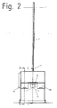
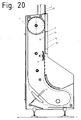
- Fig.1 and Fig.2 each show a side view and a front view of a device according to the invention for separating and aligning position of crown corks and for conveying the isolated and position-oriented crown cork to a (not shown) closing machine.
- the device according to the invention comprises a machine cabinet 1 and a conveyor unit 2 and a movable gravity channel 3, which is provided with an end piece 4 which can be coupled to the (not shown) closing machine.
- Figure 3 Figure 4 and Figure 5 show a sectional view through an inventive device according to section line AA Fig.1 or BB off Fig.2 or CC off Fig.2 so that the machine box 1 is cut.
- This has a simple basic structure of four plastic plates 5a, 5b, 5c, 5d, which are connected by not shown clamping screws and form the framework for all components therein.
- plastic plates 5a, 5b, 5c, 5d also all necessary guides, air ducts, bearing seats, holes, etc. are incorporated.
- a removal conveyor 6 is arranged in the form of a link belt conveyor having a steep conveyor section 6a and a flat conveyor section 6b.
- the steep conveyor section 6a is inclined at an angle> 30 °, preferably> 80 ° to the support plane 7, in FIG Figure 3 that is, inclined in the plane of the drawing or parallel to the plane of the drawing.
- the angle between the flat conveyor section 6b and the level 7 is selected to be ⁇ 10 °.
- the Flat conveyor section 6b can also be parallel to the contact plane, ie horizontally.
- a chamber-like transfer station 8 is arranged, on the one hand by a plane extending parallel to the drawing plane bottom 18 and a parallel to this floor 18, exhaust ports 20 (see Figure 11 ) is limited and on the other hand limited by a lower boundary wall 9 in the direction of gravity and is open via feed openings 10a, 10b in the plastic plates 5b and 5c in the direction of the removal conveyor 6 out.
- a conveyor unit 2 is arranged, which passes through the transfer station 8 and forms a portion of the bottom 18 of the transfer station 8 in a section 2a.
- FIG. 3 Also evident in Figure 3 is a drive device 12 together with transmission gear 47 for the moving parts of the device according to the invention and exhaust openings 14a, 14b in the plastic plates 5a and 5d, which via a blower unit 13 (see Figure 5 ) are supplied with air and this transversely to the conveying direction of the removal conveyor 6 on the members 29 passes.
- the air ducts are incorporated in the plastic plates 5a, 5d.
- a filter pack 34 preferably a high surface filter for sterile air, arranged in the intake of the blower unit 13.
- a differential pressure gauge measures the pressure difference before and after the filter and thus determines the degree of contamination of the filter.
- Figure 4 and Figure 5 in particular also show a task unit 15, in which a bulk material divider 16 is arranged, the preferably automatically brought up crown corks on left and right next to the bulk material divider 16 arranged reservoir 17a, 17b (see also Figure 13 ).
- the bulk material divider 16 is slidably disposed in its holder 27 to the left or right closer to the one or the other reservoir 17a, 17b by means of an adjusting device 28, for example a servomotor or a pneumatic or hydraulic cylinder, to the distribution ratio of abandoned over the task unit 15 crown cork 21 on the two reservoir 17a, 17b and thus to affect the two removal conveyor 6 can.
- an adjusting device 28 for example a servomotor or a pneumatic or hydraulic cylinder
- Figure 6 shows a detailed view of a transfer station 8 without cover 19, which has been omitted for reasons of clarity, and thus exposes the bottom 18 of the transfer station, and a first conveying section 37 of the conveyor unit 2.
- Centrally between the feed openings 10a, 10b can be the portion 2a of the conveyor unit 2, which is embedded in the bottom 18 of the transfer station 8 and thus forms a portion of the bottom 18.
- the crown corks 21 are shown schematically, some of which have already been detected by the conveyor unit 2a and were transported upwards, while others are still collecting in a trough formed by the V-shaped lower boundary wall 9, in particular at the transfer point 50.
- Figure 6 further shows two baffles 22, whose function will be explained later, and two guide elements 23,24, the slightly offset from the conveyor unit recorded crown corks 21 on the conveyor unit 21 center.
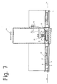
- Figure 7 is a sectional view through an inventive device according to section line DD Figure 6 and shows a view from above into the transfer station 8, that is to say a view of the lower boundary wall 9 of the transfer station 8.
- the distance between the bottom 18 and lid 19 is selected so that the crown corks 21 can not change their position with respect to a reference surface 33, ie. In other words, they can maintain the position they have when entering the transfer station 8 in the direction of the arrows 25 in the transfer station 8 and roll only over its circumference.
- Figure 7 further shows the strand 2b of the conveyor unit 2 and the returning strand 44, both of which run on a forming tube 48 as a conveyor track, preferably made of stainless steel.
- a permanent or electromagnet 26 is arranged, which is formed substantially rod-shaped, with its longitudinal axis parallel to the run 2b extending.
- magnets 26 are arranged behind one another along the section of the conveying unit 2 to be magnetized, in particular of the first conveying section 37 of the conveying unit 2.
- the magnet 26 is surrounded by soft iron elements 49, which are arranged in a U-shape around the magnet 26 in order to guide the magnetic field in the direction of the run 2b.
- the soft iron elements arranged on the side of the magnet 26 are thin-walled, the soft iron element arranged opposite the strand 2b thick-walled in order to produce a narrow magnetic field focused parallel to the strand 2b.
- Magnet 26 and soft iron elements 49 are held by an angle holder 45 which is secured with a slot 46 on the forming tube. About the slot, the distance of the magnet 26th to the upper run and thus the effect of the magnetic field on the crown 2b held on the crown 21 are set.
- Figure 12 shows a partially sectioned detail of the transition between the first 37 and further 38 conveying section of the conveyor unit.
- the magnets 26 are arranged so that their distance to the run 2b of the conveyor unit 2m increases seen in the conveying direction after the transition to reduce the effect of the magnetic field on the strand 2b and thus on the crown cork 21 conveyed thereon.
- Crown corks 21 are given as bulk material on the task unit 15 in the reservoir 17a, 17b.
- the adjustable bulk material divider 16 the distribution of the bulk material to the individual reservoir 17a, 17b are controlled.
- the crown corks 21 are scooped up by the removal conveyors 6 from the storage containers 17a, 17b.
- the removal conveyor 6 with its flat conveyor sections 6b dip into the quantities of crown corks 21 stored in the respective storage containers 17a, 17b.
- the crown corks 21 are thereby arranged by several on the removal conveyors 6, which are designed as a chain belt conveyor, for example, screwed, entrainment elements 30 detected and taken.
- the individual members 29 of the removal conveyor 6 have for this purpose but also for reasons of stability to a bent end portion 31.
- the other end region is in each case formed by a carrier element 30.
- Driving element 30 and alskanteter end portion 31 form a receptacle 32 for the crown cork 21 (see Figure 8 ), with only crown corks as in Figure 8 drawn, so pointing with its visible surface 33 in the direction of the receptacle 32, can be conveyed on the steep conveyor section 6a, since the center of gravity of such entrained crown cork 21 the Thrown out the same from the receptacle 32 prevents.
- crown corks 21 in opposite orientation than this in Figure 8 are shown, so successful with the visible surface 33 of the receptacle 32 come to lie in the receptacle 32, due to the center of gravity and the interpretation of the geometry of the entrainment 30 such entrained crown cork 21 from the removal conveyors 6 only to the steep conveyor section 6 b promoted where They then slip out of the receptacle 32 and again fall back into the respective reservoir 17a, 17b, from which it was taken to be scooped again by the respective removal conveyor 6.
- the crown corks 21 are then conveyed along with this preorientation (reference surface 33 pointing in the direction of the receptacle 32) along the steep conveying section 6a to the level of the charging openings 10a, 10b.
- a blower unit 13 exhaust openings 14a, 14b arranged, whereby in the plastic plates 5a and 5d air transverse to the conveying direction of the removal conveyor 6 is inflatable on the members, such that the crown corks 21, which are held in a preoriented manner in the individual receptacles 32 of the members 29, are blown out into the transfer station 8.
- the blowing out can either take place in rows, or several rows can be blown out together, depending on the arrangement of the openings 14a, 14b.
- the injected air can escape through openings 20 in the lid 19 of the transfer station 8 again.
- a filter pack 34 such as a high surface filter, to keep the air used to blow out the crown corks 21 as sterile as possible and reliably prevent the adhesion of dust or other perturbation elements which could form the basis for subsequent mold growth on the crown cork 21.
- the crown corks 21 fall over the charging openings 10a, 10b into the transfer station 8, by they along the lower boundary wall 9 of the transfer station 8 and along it already located other crown cork 21 (see also Figure 6 ) strive towards the lowest point of the transfer station 8.
- the lowest point of the transfer station 8 is preferably arranged directly above the section 2a of the conveyor unit 2 or more precisely directly above the run 2b of the section 2a of the conveyor unit 2.
- the strand 2b is inserted for this purpose in the bottom 18 of the transfer station 8 or runs in a groove of the same.
- the feeding of the transfer station 8 takes place from both removal conveyors 6.
- the relative position of the two removal conveyors 6 to each other during conveyance is constant and either the carrier elements 30 on the individual links 29 with respect to their vertical distance to the contact surface 7 of the device are always positioned differently or the two feed openings 10a, 10b have a different vertical distance to the contact surface 7 of the device. This ensures that the two removal conveyor 6 never feed the transfer station 8 at the same time, but always slightly offset in time, whereby a mutual obstruction of the charging process is avoided.
- the transfer station 8 further comprises baffle plates 22, which are intended to prevent when loading the transfer station 8 that crown corks 21 are deflected too far from the lower boundary wall 9 of the transfer station 8.
- the distance between the bottom 18 and lid 19 of the transfer station is anyway smaller than the diameter of the crown cork 21 and in practice slightly larger than the thickness, so that a change in position of the crown cork 21 relative to the orientation of the reference surface 33 is not possible.
- the reference surface 33 is the visible surface 33 of the crown cork 21, which must be handled very gently, since this is usually provided with a logo or an inscription and this may not be scratched during the manipulation of the invention or even destroyed.
- the crown corks located in the transfer station 8 take in the course of their residence in the transfer station 8 and a position above (depending on the approach) the section 2b of the conveyor unit 2, where they adhere to the strand 2b due to its magnetization and in the conveying direction 35 of Be conveyed conveyor unit 2.
- baffles 23,24 are provided in the transfer station 8.
- a first conveyor section 2 which is arranged directly after the transfer station 8 and is independent of the transfer station 8, carries at least one conveyor unit 2, which has a conveying direction component pointing away from the contact surface 7 of the device.
- the crown corks 21 are conveyed away after the separation and positional orientation with respect to the support level 7 upwards from the transfer station 8, whereby they can also be placed far below, within reach of operating personnel.
- the conveying section 37 extends vertically, but also inclined courses of the conveying section 37 are conceivable as long as they have a conveying direction component pointing away from the supporting plane 7.
- the device of the invention requires by conveying away the crown cork 21 upwards from the transfer station 8 a small footprint and allows the rapid up-conveying the already isolated and position-oriented crown cork 21 to a height where the further transport can be done horizontally.
- the conveyor unit 2 itself has subsequent to the first conveyor section 37 further conveyor sections or can also be multi-part ie. be constructed of several other conveyor units, depending on the distance to the closing machine.
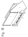
- the conveyor section 37 is in a defined height, in which a horizontal further transport of the crown cork 21 is possible without disturbing the ground standing systems or from which the crown corks 21 can be optimally supplied to the closing machine, in a further, horizontally extending Conveyor section 38 via.
- the axis of curvature 11 of the transition between the two conveyor sections 37, 38 runs parallel to the surface of the track 2b or reference surface 33 of the crown cork 21 transported on the conveyor unit.
- the transition takes place without deflection rollers and with a large radius, preferably> 200 mm, particularly preferably between 300 mm and 600mm.
- the clamping device 39 for the conveyor unit 2 is arranged at the level of the transfer station 8.
- the distance between the run 2b and the magnets 26 of the conveyor track 48 increases starting with the transition from the conveyor section 37, so that over a majority of the conveyor section 38 no magnetic force acts.
- the gentle decrease of the magnetic force prevents a jam from forming on crown corks 21 at the beginning of the conveying section 38, as would be the case if the magnetic force were suddenly eliminated and crown corks 21 still held by the conveying section 37 are still pushed by magnetic force.
- the horizontally extending conveyor section 38 has a length that extends as a rule to above the closing machine not shown here.
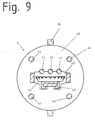
- the conveyor section 38 there goes into a gravity channel 3, which is constructed from a plurality of flanges 40, all of which are connected to each other by the flanges 40 penetrating rods 41 (see Figure 9 ).
- the flanges 40 are additionally arranged on the outside of the same, the flanges 40 interconnecting stiffening profiles 36 with each other connected to additionally stiffen and stabilize the gravity channel 3.
- Each flange 40 is provided with a guide recess 42 within which a guide track 43 for gravity-driven crown corks 21 is held.
- the guide track 43 is formed to protect the reference surface 33 of the crown cork 21 from a good sliding properties having plastic, for example polyethylene (PE) or Teflon (PTFE).
- the 15 to 20 show an alternative embodiment of the invention.
- This alternative embodiment variant is shown with reference to a device for separating and position aligning metallic container closures with only one removal conveyor 6.
- a second removal conveyor according to the embodiment according to Fig.1 to 14 can be provided.
- This alternative embodiment differs from that in the Fig. 1 to 14 embodiment described essentially in that compared to the bottom 18 of the transfer station 8 and with respect to the steep conveyor section 6a of the removal conveyor 6 substantially parallel thereto and therefore forming a kind of top management forming an additional air guide element 52, as in Figure 18 and 19 is shown provided.
- the spoiler 52 thus assumes in the transfer station 8, the functionality of in Figure 7 the cover 19 of the transfer station 8 described above embodiment, ie., That the distance between the bottom 18 and air guide 52 is selected so that the crown corks 21 can not change their position with respect to a reference surface 33, ie. in other words, that they can maintain the position they have when entering the transfer station 8 in the direction of arrow 25 in the transfer station 8 and roll only over its circumference.
- the air guide 52 may be an integral part of the lid 19 or be installed as a separate part that is adjacent to the lid 19 directly.
- the lid 19 does not require exhaust air openings 20 in this case.
- the additional air guide element 52 comprises a cavity 52a which is acted upon by overpressure and has a lateral opening 54, via which the air guide element 52 is supplied with air as blow-out medium via the air guide channel 56 supplying the blow-off openings 14b and incorporated in the plastic plate 5d.
- the air guide element 52 also has gill-like openings / slots 53, which are directed obliquely into the interior of the transfer station 8 in order to convey the crown corks 21 in the direction of run 2b of the conveyor unit 2 (direction of the arrow 25 or transfer point 50), which is a part the rear wall 18 of the transfer station 8 forms.
- Figure 19 is a sectional view along the line KK Figure 16 represents.
- the distribution of the gill-like openings / slots 53 over the width 58 of the air-guiding element 52 is different.
- a first section 55 of the air guide element 52 which is opposite the steep conveyor section 6a of the removal conveyor 6, the arrangement of the gill-like openings / slots 53 is substantially flat, so that they are distributed on the one hand along the entire width 58a of the steep conveyor section 6a of the removal conveyor 6, On the other hand, but also along the height 59 of the steep conveyor section 6 a are distributed, within which the crown cork 21 via the feed openings 10 b in the Transfer station 8 can be blown out or should.
- the distribution of the gill-like openings / slots 53 over the height 59 takes place in such a way that they are distributed over the entire height 59 in the area of the charging opening 10b, but only over a smaller portion along this height in the area of the discharge openings 14b. It is thereby achieved that the crown corks 21 are blown out faster in the region of the charging opening 10b than the crown corks 21 projecting in the rear in the region of the exhaust openings 14b, whereby a crown cork jam can be prevented in a targeted manner.
- the arrangement of the gill-like openings / slots 53 is substantially linear, so that they are distributed along the entire width 58b of the transfer station 8, but at the same time the course the lower boundary wall 9 of the transfer station 8 adjoining the air guiding element 52, offset slightly above it, is distributed along a height 60 which essentially corresponds to the diameter of the crown corks 21.
- the providence of the additional air guiding element 52 causes the crown corks 21 lying in the limbs of the steep conveying section 6a of the removal conveyor 6 to be pushed not only starting from the blowing openings 14b into the transfer station 8, thus forcing one crown cork ahead of the other, but all crown corks of a link the removal conveyor 6 can be pushed out simultaneously.
- the members of the removal conveyor 6 can be made wider and two removal conveyor 6 are replaced by a single removal conveyor 6 with the same width as the total width of the two individual, as in the in the Fig.15 to 20 embodiment shown is the case.
- an additional air guide element 52 in any case contributes to an improvement of the blowout of the crown cork 21 from the removal conveyor 6 independently of whether the device according to the invention two removal conveyor 6, as in the Fig.1 to 14 shown or a removal conveyor 6 as in the Fig.15 to 20 has shown.
- such a spoiler 52 proves to be advantageous in connection with the formation of the lower boundary wall 9 of the transfer station 8 with an elevated transfer point 50 with respect to the remaining areas of the lower boundary wall 9, as shown in FIG Figure 6 is shown in dashed lines, since in this case the crown cork 21 against gravity to the higher transfer point 50 must be transported, which is supported by the additional blow-out of the air guide 52 both in the area of / the removal conveyor 6 and in the transfer station 8, so that it is obvious that an inventive air guide element 52 also in a device as in Fig.1 to 14 shown, can be used.
- a magnetic system 51 is arranged to bind the crown cork 21 in this section more strongly to the members of the removal conveyor 6, to drop the crown cork 21 to prevent this height and to prevent wedging of the crown cork 21 with a arranged in this height before the steep conveyor section 21 cover.
- a magnetic system 51 is arranged to bind the crown cork 21 in this section more strongly to the members of the removal conveyor 6, to drop the crown cork 21 to prevent this height and to prevent wedging of the crown cork 21 with a arranged in this height before the steep conveyor section 21 cover.
Landscapes
- Engineering & Computer Science (AREA)
- Mechanical Engineering (AREA)
- Attitude Control For Articles On Conveyors (AREA)
Claims (22)
- Dispositif servant à désolidariser et disposer des fermetures métalliques de contenants (21) ainsi qu'à transporter les fermetures de contenants (21) désolidarisées et disposées, de préférence des capsules, vers une machine de transformation, de préférence une machine à encapsuler, le dispositif comprenant- Au moins un réservoir (17a, 17b) et/ou une unité de remise (15) pour les fermetures de contenant (21),- Au moins un convoyeur de prélèvement (6) pour prélever et prédisposer les fermetures de contenant (21) à partir du réservoir (17a, 17b) au moins au nombre de un, sachant que le convoyeur de prélèvement (6) au moins au nombre de un, présente une section de transport verticale (6a) dont la surface de convoyage dessine un angle > 30° , de préférence > 80° avec la surface de levage lorsque le dispositif est en position de service, ainsi que- Au moins une unité de transport (2) transportant les fermetures de contenant (21) désolidarisées et orientées vers la machine de transformation, laquelle contacte les fermetures de contenant (21) à une surface de référence (33) des fermetures de contenant à l'aide d'une surface d'appui (2b)- Ainsi qu'une station de transfert (8) dans laquelle les fermetures de contenant sont propulsés hors de la section de transport verticale (6a) perpendiculairement au sens de transport du convoyeur de prélèvement (6) au moins au nombre de un, et à l'aide de laquelle les fermetures de contenant (21) sont remises isolément et orientées à l'unité de transport (2)sachant qu'une première section de transport (37) de l'unité de transport (2) au moins au nombre de une et transportant les fermetures de contenant (21) isolées et positionnées, directement disposée après la station de transfert (8) présente un composant donnant le sens de transport depuis la zone de soulèvement (7) du dispositif, caractérisé en ce que
l'unité de transport (2) au moins au nombre de une, englobe un compartiment (2b) d'une sangle de transport sans fin ou d'une bande à membres ou à plaques transportant les fermetures de contenant (21), passant le long d'une ligne de transport permanente ou électromagnétique conçue comme une poutre magnétique, reposant du moins en partie sur celle-ci ou dirigée à une distance restreinte de celle-ci et propulsant les fermetures de contenant (21) hors de la station de transfert (8). sachant que ces aimants (26) de la poutre magnétique sont essentiellement en forme de tige dont l'axe longitudinal est parallèle au compartiment (2b),
et sachant que les aimants (26) sont entourés en forme de U d'éléments en fer doux (49) afin d'orienter le champ magnétique dans le sens du compartiment (2b). - Dispositif selon la revendication 1, caractérisé en ce qu'est prévue une deuxième section de transport (38) de l'unité de transport (2) au moins au nombre de une, essentiellement horizontale en position de service du dispositif et raccordée à la première section de transport (37), sachant que l'axe de courbure (11) de transition entre les deux sections de transport (37, 38) est parallèle à la surface d'appui (2b) de l'unité de transport (2) et à la surface supérieure de référence (33) des fermetures de contenant (21) transportées sur l'unité de transport (2) et que la transition se fait de préférence sans galet de renvoi.
- Dispositif selon l'une des revendications 1 à 2, caractérisé en ce que la station de transfert (8) est disposée à une hauteur mesurée à partir de la zone de soulèvement (7) du dispositif comprise entre 1m et 3m, de préférence entre 1m et 2m.
- Dispositif selon l'une des revendications 1 à 3 caractérisée en ce que la station de transfert (8) est disposée directement à côté du convoyeur de prélèvement (6) au moins au nombre de un et comporte un fond (18) et un couvercle (19) essentiellement parallèles à la section de transport verticale (6a) du convoyeur de prélèvement (6), sachant qu'au moins une ouverture de chargement (10a, 10b) est prévue et au moyen de laquelle les fermetures de contenant (21) sont transportées du convoyeur de prélèvement (6) à la station de transfert (8).
- Dispositif selon la revendication 4, caractérisé en ce que l'écart entre le fond (18) et le couvercle (19) ne permet le chargement de la station de transfert (8) avec des fermetures de contenant (21) du convoyeur de prélèvement (6) au moins au nombre de un en fonction de leur surface de référence (33) que dans la position dans laquelle les fermetures de contenant sont transportés dans le convoyeur de prélèvement (6).
- Dispositif selon l'une des revendications 4 ou 5, caractérisé en ce qu'une section partielle (2a) de l'unité de transport (2) au moins au nombre de une, constitue une section du fond (18) de la station de transfert (8) de telle sorte que les fermetures de contenant (21) transportées et positionnées du convoyeur de prélèvement (6) au moins au nombre de un à la station de transfert (8) atterrissent sur l'unité de transport (2) sur leur surface supérieure de référence (33) en fonction au moins de la quantité et de la géométrie de la station de transfert (8) et selon le principe aléatoire.
- Dispositif selon l'une des revendications 4 à 6, caractérisé en ce qu'une paroi de limitation (9) de la station de transfert (8) inférieure en position de service du dispositif, reliant le fond (18) et le couvercle (19) entre eux est prévue, laquelle présente un point inférieur faisant office de point de transfert (50) en position de service du dispositif, lequel est disposé en-dessous de l'ouverture de chargement (10a, 10b) au moins au nombre de une, et au-dessus de l'unité de transport (2) au moins au nombre de une et prévue dans le fond (18) de la station de transfert (8).
- Dispositif selon l'une des revendications 4 à 6, caractérisée en ce qu'une paroi de délimitation (9) de la station de transfert (8), inférieure en position de service du dispositif, reliant le fond (18) et le couvercle (19) entre eux est prévue, laquelle présente un point supérieur faisant office de point de transfert (50) en position de service du dispositif, lequel est disposé au-dessus de l'unité de transport (2) au moins au nombre de une et prévue dans le fond (18) de la station de transfert.
- Dispositif selon l'une des revendications 1 à 8, caractérisé en ce que le convoyeur de prélèvement (6) au moins au nombre de un, fabriqué de préférence en acier anticorrosion et/ou résistant aux acides, est un convoyeur à bande à membrures sans fin avec une section de transport plate (6b) plongeant dans le réservoir (17a, 17b), dont chaque membre (29), observé dans le sens du transport, présente une première section d'extrémité portant un élément d'entraînement (30) doté d'un chanfrein et une deuxième section d'extrémité dans laquelle les membres (29) ont de préférence un bord relevé et la zone entre l'élément d'entraînement (30) et le bord relevé privilégié est prévu pour réceptionner les fermetures de contenant (21) alignés les unes à côté des autres.
- Dispositif selon l'une des revendications 4 à 9, caractérisé en ce qu'au niveau de l'ouverture d'entraînement (10a, 10b) au moins au nombre de une, est disposée au moins une ouverture d'évacuation (14a, 14b) actionnée par une soufflerie (13) et destinée à transporter les fermetures de contenant (21) alignés du convoyeur de prélèvement (6) au moins au nombre de un à la station de transfert (8).
- Dispositif selon l'une des revendications 7 à 10, caractérisé en ce qu'un élément conducteur d'air (52) supplémentaire est prévu, lequel est parallèle au couvercle (19), de préférence faisant partie intégrante du couvercle (19) et est disposé de sorte à recouvrir au moins une partie de la section de transport verticale (6a) et au moins une partie de la station de transfert (8) et présente une ouverture/fente (53) actionnée par une soufflerie (13) dans la station de transfert (8) et/ou dirigée vers la section verticale (6a) pour transporter les fermetures de contenant (21) alignées d'une part de la section de transport verticale (6a) à la station de transfert (8) et pour transporter d'autre part les fermetures de contenant (21) se trouvant déjà dans la station de transfert (8) en direction du point de transfert (50).
- Dispositif selon l'une des revendications 1 à 11, caractérisé en ce que la vitesse de transport de l'unité de transport (2) au moins au nombre de une correspond à un multiple de la vitesse de transport du convoyeur de prélèvement (6) au moins au nombre de un.
- Dispositif selon l'une des revendications 1 à 12, caractérisé en ce que la largeur du compartiment (2b) de la bande de transport de l'unité de transport (2) au moins au nombre de une est plus petite ou égale à la plus grande largeur des fermetures de contenant (21) à transporter.
- Dispositif selon l'une des revendications 4 à 12, caractérisé en ce que la section de transport verticale (6a) du convoyeur de prélèvement (6), le fond (18) et le couvercle (19) de la station de transfert (8) ainsi que la première section de transport (37) de l'unité de transport (2) sont verticaux.
- Dispositif selon l'une des revendications 9 à 14, caractérisé en ce qu'un système magnétique (51) est placé sur la face du convoyeur de prélèvement (6) au moins au nombre de un opposée aux éléments d'entraînement (30) de la section de transport verticale (6a).
- Dispositif selon l'une des revendications 1 à 15, caractérisé en ce que sont prévus deux convoyeurs de prélèvement (6) parallèles et en ce que la station de transfert (8) ainsi qu'une unité de transport (2) transportant les fermetures de contenant (21) isolées et positionnées vers une machine de transformation sont disposées entre les convoyeurs de prélèvement (6), sachant que la station de transfert (2) présente deux ouvertures de chargement.
- Dispositif selon la revendication 16, caractérisé en ce que la position relative des deux convoyeurs de prélèvement (6) l'un par rapport à l'autre est constante pendant le transport et en ce que soit les éléments d'entraînement (30) sur les membrures (29) sont sans cesse positionnés différemment par rapport à leur écart vertical avec la zone de soulèvement (7) du dispositif soit les deux ouvertures de chargement (10a, 10b) présentent un écart vertical différent avec la zone de soulèvement (7) du dispositif.
- Dispositif selon la revendication 16 ou 17, caractérisé en ce que la paroi de délimitation inférieure (9) de la station de transfert (8) est en forme de V, sachant que chaque côté relie respectivement le point le plus bas d'une ouverture de chargement (10a, 10b) au point le plus bas de la station de transfert (8) par rapport à la zone de soulèvement (7).
- Dispositif selon l'une des revendications 16 à 18, caractérisé en ce qu'entre les deux convoyeurs de prélèvement (6) et, en position de service du dispositif, en-dessous de la station de transfert (8) est prévue une unité de remise (15), laquelle présente un déverseur de matière en vrac (16) de préférence en forme de coin, lequel distribue les fermetures de contenant (21) isolées et positionnées sur les deux convoyeurs de prélèvement (6).
- Dispositif selon la revendication 19, caractérisé en ce que le déverseur de matière en vrac (16) est placé entre les convoyeurs de prélèvement (6) tout en étant mobile afin d'influencer la distribution des fermetures de contenant (21) transférés sur les deux convoyeurs de prélèvement (6).
- Dispositif selon l'une des revendications 1 à 20, caractérisé en ce qu'entre l'unité de transport (2) et la machine de transformation, une gouttière de gravitation (3) est disposée, laquelle présente une ligne de guidage (43), sur laquelle les fermetures de contenant (21) glissent en raison de la force gravitationnelle en direction de la machine de transformation, la ligne de guidage (43) étant en plastique, de préférence en polyéthylène ou en téflon ou recouverte d'une couche en plastique, de préférence en polyéthylène ou en téflon, du moins au niveau de la zone de contact avec les fermetures de contenant (21).
- Dispositif selon l'une des revendications 1 à 21, caractérisé en ce que les fermetures de contenant (21) sont en fait des capsules et les surfaces supérieures de référence (33) sont formées par le dos des capsules.
Applications Claiming Priority (2)
| Application Number | Priority Date | Filing Date | Title |
|---|---|---|---|
| AT0059708U AT10979U1 (de) | 2008-10-17 | 2008-10-17 | Sortiervorrichtung |
| PCT/EP2009/063672 WO2010043720A1 (fr) | 2008-10-17 | 2009-10-19 | Dispositif de séparation et de positionnement de fermetures métalliques de contenant |
Publications (2)
| Publication Number | Publication Date |
|---|---|
| EP2346757A1 EP2346757A1 (fr) | 2011-07-27 |
| EP2346757B1 true EP2346757B1 (fr) | 2013-07-10 |
Family
ID=41402122
Family Applications (1)
| Application Number | Title | Priority Date | Filing Date |
|---|---|---|---|
| EP09744656.1A Active EP2346757B1 (fr) | 2008-10-17 | 2009-10-19 | Dispositif de séparation et de positionnement de fermetures métalliques de contenant |
Country Status (4)
| Country | Link |
|---|---|
| US (1) | US8172070B2 (fr) |
| EP (1) | EP2346757B1 (fr) |
| AT (1) | AT10979U1 (fr) |
| WO (1) | WO2010043720A1 (fr) |
Families Citing this family (17)
| Publication number | Priority date | Publication date | Assignee | Title |
|---|---|---|---|---|
| AT13042U1 (de) | 2011-11-08 | 2013-05-15 | Gassner Gmbh | Vorrichtung und verfahren zur behandlung und zuführung von behälterverschlüssen |
| DE112012004655B4 (de) * | 2011-11-08 | 2017-07-13 | Gassner Gmbh | Vorrichtung und Verfahren zur Behandlung und Zuführung von Behälterverschlüssen |
| AT13041U1 (de) | 2011-11-08 | 2013-05-15 | Gassner Gmbh | Beschickungsvorrichtung für behälterverschlüsse |
| JP6326286B2 (ja) * | 2014-05-14 | 2018-05-16 | 日本電子株式会社 | 容器供給ユニット及び自動分析装置 |
| EP2944575A1 (fr) * | 2014-05-16 | 2015-11-18 | JT International S.A. | Procédé de production d'un emballage d'articles à fumer |
| US9376301B1 (en) | 2015-07-16 | 2016-06-28 | Jalbert Automatisation Inc. | Adjustable cap sorter |
| CN107244540B (zh) * | 2017-05-26 | 2019-10-25 | 陈泰宇 | 一种瓶盖整列装置 |
| CN109279554A (zh) * | 2018-11-14 | 2019-01-29 | 楚天科技股份有限公司 | 一种具有抽真空压塞机构的轧盖机及方法 |
| DE102018129548A1 (de) | 2018-11-23 | 2020-05-28 | Krones Ag | Vorrichtung und Verfahren zum Zuführen von Verschlüssen zu einem Verschließer zum Verschließen von Behältern |
| CN109850532B (zh) * | 2019-04-17 | 2023-04-14 | 深圳市红标点科技有限公司 | 一种书籍输送带设备使用的书籍收拢装置 |
| CN110371349B (zh) * | 2019-07-15 | 2023-08-11 | 桂林电子科技大学 | 一种管道自动封盖装置 |
| CN110355441A (zh) * | 2019-07-25 | 2019-10-22 | 浙江硕而博科技股份有限公司 | 一种焊锡机上的传送机构 |
| CN112645038A (zh) * | 2019-10-10 | 2021-04-13 | 江苏满晟科技发展有限公司 | 一种蚯蚓培养料装筐机 |
| CN110668155A (zh) * | 2019-10-28 | 2020-01-10 | 青岛萨沃特机器人有限公司 | 料盒夹持换道及输送装置 |
| CN115991452B (zh) * | 2023-03-22 | 2023-06-27 | 江苏尚纯自动化技术有限公司 | 一种压盖高度可调的包装机 |
| CN116767771B (zh) * | 2023-08-16 | 2023-10-31 | 江苏金陵干燥科技有限公司 | 一种多段多层固体废弃物螺旋输送装置 |
| CN117735166B (zh) * | 2024-02-20 | 2024-04-19 | 云南浩翔包装制品有限公司 | 一种附带输送轨道防卡功能的牛奶瓶盖输送装置 |
Family Cites Families (23)
| Publication number | Priority date | Publication date | Assignee | Title |
|---|---|---|---|---|
| US1933320A (en) | 1931-06-08 | 1933-10-31 | Gen Electric | Winding machine |
| US3106281A (en) * | 1959-11-16 | 1963-10-08 | Parke Davis & Co | Automatic feeder mechanism for orienting relatively small articles |
| DE1918627B2 (de) | 1969-04-12 | 1977-07-21 | Vorrichtung zum vereinzeln und parallelisieren laenglicher textilkoerper | |
| DE1933320A1 (de) | 1969-07-01 | 1971-01-14 | Rump Joh Moritz | Ordnungsvorrichtung fuer Verschlussdeckel fuer Konservengefaesse,insbesondere weithalsige Flaschen bzw. Glaeser |
| JPS522538B2 (fr) | 1972-03-13 | 1977-01-22 | ||
| JPS54366A (en) * | 1978-06-12 | 1979-01-05 | Hitachi Metals Ltd | Method of magnetically conveying magnetic bar |
| JPS5516827A (en) * | 1978-07-17 | 1980-02-05 | Ryugoro Sakaguchi | Automatic aligning device for bottle sealing caps |
| JPS5765738A (en) | 1980-10-07 | 1982-04-21 | Idemitsu Petrochem Co Ltd | Polypropylene resin composition and thermoforming resin sheet obtained therefrom |
| JPS5765738U (fr) * | 1980-10-08 | 1982-04-20 | ||
| US4735343A (en) * | 1984-03-19 | 1988-04-05 | Michael Herzog | Feeder for bottle capper |
| DE3603159A1 (de) * | 1986-02-03 | 1987-08-06 | Schaeffer Scovill Verbindung | Foerdereinrichtung zum hochfoerdern von kleinteilen, insbesondere knopfteilen, aus einem vorratssumpf |
| US5333718A (en) * | 1993-08-24 | 1994-08-02 | Pannell Lorris O | Apparatus for handling plastic eating utensils |
| US5394972A (en) | 1994-02-22 | 1995-03-07 | Aidlin; Stephen H. | Variable angle conveyor assembly |
| US5586637A (en) | 1994-02-22 | 1996-12-24 | Aidlin; Samuel S. | Variable angle conveyor assembly with stepped cleat |
| NL9401416A (nl) * | 1994-08-31 | 1996-04-01 | Thomassen & Drijver | Inrichting voor het richten van deksels. |
| DE19700512B4 (de) | 1997-01-09 | 2007-01-11 | Firma Erwin Gaßner | Sortier- und Zuführungsmaschine |
| AT3964U1 (de) | 1999-10-19 | 2000-11-27 | Gassner Gmbh | Sortiergerät |
| US6491152B1 (en) | 2001-04-09 | 2002-12-10 | Gebo Corporation | Conveyor assembly |
| US7040489B2 (en) * | 2003-10-10 | 2006-05-09 | Alcoa Closure Systems International, Inc. | Object orienting and sorting apparatus |
| DE102004030667B4 (de) * | 2004-06-24 | 2017-10-19 | Gassner Ges.M.B.H. | Sortiergerät |
| FR2876990B1 (fr) | 2004-10-25 | 2007-01-12 | Sidel Sas | Perfectionnement aux machines d'appret utilisees pour orienter des objets en vue de l'alimentation d'une chaine de preparation de produits comportant lesdits objets |
| US7246695B2 (en) * | 2005-09-14 | 2007-07-24 | Alcoa Closure Systems International, Inc. | Conveyor apparatus for conveying closure |
| US7597189B2 (en) * | 2006-10-25 | 2009-10-06 | Fowler Products Company Llc | Cap sorter and associated cleat |
-
2008
- 2008-10-17 AT AT0059708U patent/AT10979U1/de not_active IP Right Cessation
-
2009
- 2009-10-19 WO PCT/EP2009/063672 patent/WO2010043720A1/fr active Application Filing
- 2009-10-19 EP EP09744656.1A patent/EP2346757B1/fr active Active
-
2011
- 2011-04-15 US US13/066,510 patent/US8172070B2/en active Active
Also Published As
| Publication number | Publication date |
|---|---|
| US20110258965A1 (en) | 2011-10-27 |
| EP2346757A1 (fr) | 2011-07-27 |
| US8172070B2 (en) | 2012-05-08 |
| AT10979U1 (de) | 2010-02-15 |
| WO2010043720A1 (fr) | 2010-04-22 |
Similar Documents
| Publication | Publication Date | Title |
|---|---|---|
| EP2346757B1 (fr) | Dispositif de séparation et de positionnement de fermetures métalliques de contenant | |
| DE102006019822B4 (de) | Vorrichtung zum Fördern und Vereinzeln von ferromagnetischen Teilen | |
| EP2623441B1 (fr) | Dispositif de stockage pour récipients et procédé de stockage de récipients | |
| EP3115322B1 (fr) | Procede et dispositif destines a la depalettisation de pneus | |
| EP2032484B1 (fr) | Transporteur pneumatique pour bouteilles | |
| EP3315420B1 (fr) | Machine d'emballage par emboutissage | |
| EP1952705A2 (fr) | Cartouche de vidage et procédé de vidage de combles de puits remplis de produits en forme de tiges | |
| AT507740B1 (de) | Sortiergerät | |
| EP2287079A2 (fr) | Dispositif de groupement et/ou de séparation d'articles | |
| DE3806168A1 (de) | Foerdereinrichtung fuer gegenstaende | |
| EP2402269A1 (fr) | Dispositif d'évacuation | |
| EP3476779B1 (fr) | Dispositif et procédé de triage et de séparation des capuchons de fermeture | |
| DE102013102843B4 (de) | Verfahren und Vorrichtung zum Abtransportieren von Packungsbehältern | |
| DE102016122462A1 (de) | Vorrichtung zum Sortieren und Fördern von Behälterverschlüssen | |
| EP3670399A1 (fr) | Transporteur en cascade et procédé de tri et de transport de fermetures de récipient | |
| EP1578678B1 (fr) | Dispositif de distribution continue de sachets | |
| EP3398886B1 (fr) | Dispositif de transport d'objets | |
| DE4342084C2 (de) | Vorrrichtung zum Ausrichten von Gegenständen | |
| DE102018124212A1 (de) | Förderstrecke für einen Transport einer Vielzahl von Artikeln und Verfahren zum Anpassen und/oder Betreiben einer Förderstrecke | |
| DE69402908T2 (de) | Luftunterstützungsanlage für eine Stange von Metalldosenenden | |
| DE19751967B4 (de) | Einrichtung insbesondere zur Gasseneinteilung bzw. zum Transport,von Transportgut,z. B. Flaschen, Getränkedosen und dergleichen | |
| EP2776347B1 (fr) | Dispositif d'alimentation pour fermetures de contenant | |
| EP3822201A1 (fr) | Dispositif de transport et procédé de tri des marchandises de détail | |
| DD148602A1 (de) | Einrichtung zum vereinzeln und sortieren von staeben | |
| EP3015003B1 (fr) | Dispositif de tri pour des articles longs, en particulier pour des cigarettes |
Legal Events
| Date | Code | Title | Description |
|---|---|---|---|
| PUAI | Public reference made under article 153(3) epc to a published international application that has entered the european phase |
Free format text: ORIGINAL CODE: 0009012 |
|
| 17P | Request for examination filed |
Effective date: 20110517 |
|
| AK | Designated contracting states |
Kind code of ref document: A1 Designated state(s): AT BE BG CH CY CZ DE DK EE ES FI FR GB GR HR HU IE IS IT LI LT LU LV MC MK MT NL NO PL PT RO SE SI SK SM TR |
|
| AX | Request for extension of the european patent |
Extension state: AL BA RS |
|
| DAX | Request for extension of the european patent (deleted) | ||
| 17Q | First examination report despatched |
Effective date: 20120223 |
|
| GRAP | Despatch of communication of intention to grant a patent |
Free format text: ORIGINAL CODE: EPIDOSNIGR1 |
|
| GRAS | Grant fee paid |
Free format text: ORIGINAL CODE: EPIDOSNIGR3 |
|
| GRAA | (expected) grant |
Free format text: ORIGINAL CODE: 0009210 |
|
| AK | Designated contracting states |
Kind code of ref document: B1 Designated state(s): AT BE BG CH CY CZ DE DK EE ES FI FR GB GR HR HU IE IS IT LI LT LU LV MC MK MT NL NO PL PT RO SE SI SK SM TR |
|
| REG | Reference to a national code |
Ref country code: GB Ref legal event code: FG4D Free format text: NOT ENGLISH |
|
| REG | Reference to a national code |
Ref country code: CH Ref legal event code: EP Ref country code: AT Ref legal event code: REF Ref document number: 620857 Country of ref document: AT Kind code of ref document: T Effective date: 20130715 |
|
| REG | Reference to a national code |
Ref country code: IE Ref legal event code: FG4D Free format text: LANGUAGE OF EP DOCUMENT: GERMAN |
|
| REG | Reference to a national code |
Ref country code: DE Ref legal event code: R096 Ref document number: 502009007544 Country of ref document: DE Effective date: 20130905 |
|
| PG25 | Lapsed in a contracting state [announced via postgrant information from national office to epo] |
Ref country code: SI Free format text: LAPSE BECAUSE OF FAILURE TO SUBMIT A TRANSLATION OF THE DESCRIPTION OR TO PAY THE FEE WITHIN THE PRESCRIBED TIME-LIMIT Effective date: 20130710 |
|
| REG | Reference to a national code |
Ref country code: NL Ref legal event code: T3 |
|
| REG | Reference to a national code |
Ref country code: LT Ref legal event code: MG4D |
|
| PG25 | Lapsed in a contracting state [announced via postgrant information from national office to epo] |
Ref country code: PT Free format text: LAPSE BECAUSE OF FAILURE TO SUBMIT A TRANSLATION OF THE DESCRIPTION OR TO PAY THE FEE WITHIN THE PRESCRIBED TIME-LIMIT Effective date: 20131111 Ref country code: IS Free format text: LAPSE BECAUSE OF FAILURE TO SUBMIT A TRANSLATION OF THE DESCRIPTION OR TO PAY THE FEE WITHIN THE PRESCRIBED TIME-LIMIT Effective date: 20131110 Ref country code: HR Free format text: LAPSE BECAUSE OF FAILURE TO SUBMIT A TRANSLATION OF THE DESCRIPTION OR TO PAY THE FEE WITHIN THE PRESCRIBED TIME-LIMIT Effective date: 20130710 Ref country code: LT Free format text: LAPSE BECAUSE OF FAILURE TO SUBMIT A TRANSLATION OF THE DESCRIPTION OR TO PAY THE FEE WITHIN THE PRESCRIBED TIME-LIMIT Effective date: 20130710 Ref country code: NO Free format text: LAPSE BECAUSE OF FAILURE TO SUBMIT A TRANSLATION OF THE DESCRIPTION OR TO PAY THE FEE WITHIN THE PRESCRIBED TIME-LIMIT Effective date: 20131010 Ref country code: SE Free format text: LAPSE BECAUSE OF FAILURE TO SUBMIT A TRANSLATION OF THE DESCRIPTION OR TO PAY THE FEE WITHIN THE PRESCRIBED TIME-LIMIT Effective date: 20130710 Ref country code: CY Free format text: LAPSE BECAUSE OF FAILURE TO SUBMIT A TRANSLATION OF THE DESCRIPTION OR TO PAY THE FEE WITHIN THE PRESCRIBED TIME-LIMIT Effective date: 20130626 |
|
| PG25 | Lapsed in a contracting state [announced via postgrant information from national office to epo] |
Ref country code: ES Free format text: LAPSE BECAUSE OF FAILURE TO SUBMIT A TRANSLATION OF THE DESCRIPTION OR TO PAY THE FEE WITHIN THE PRESCRIBED TIME-LIMIT Effective date: 20131021 Ref country code: LV Free format text: LAPSE BECAUSE OF FAILURE TO SUBMIT A TRANSLATION OF THE DESCRIPTION OR TO PAY THE FEE WITHIN THE PRESCRIBED TIME-LIMIT Effective date: 20130710 Ref country code: PL Free format text: LAPSE BECAUSE OF FAILURE TO SUBMIT A TRANSLATION OF THE DESCRIPTION OR TO PAY THE FEE WITHIN THE PRESCRIBED TIME-LIMIT Effective date: 20130710 Ref country code: FI Free format text: LAPSE BECAUSE OF FAILURE TO SUBMIT A TRANSLATION OF THE DESCRIPTION OR TO PAY THE FEE WITHIN THE PRESCRIBED TIME-LIMIT Effective date: 20130710 Ref country code: GR Free format text: LAPSE BECAUSE OF FAILURE TO SUBMIT A TRANSLATION OF THE DESCRIPTION OR TO PAY THE FEE WITHIN THE PRESCRIBED TIME-LIMIT Effective date: 20131011 |
|
| PG25 | Lapsed in a contracting state [announced via postgrant information from national office to epo] |
Ref country code: CY Free format text: LAPSE BECAUSE OF FAILURE TO SUBMIT A TRANSLATION OF THE DESCRIPTION OR TO PAY THE FEE WITHIN THE PRESCRIBED TIME-LIMIT Effective date: 20130710 |
|
| BERE | Be: lapsed |
Owner name: GASSNER GMBH Effective date: 20131031 |
|
| PG25 | Lapsed in a contracting state [announced via postgrant information from national office to epo] |
Ref country code: SK Free format text: LAPSE BECAUSE OF FAILURE TO SUBMIT A TRANSLATION OF THE DESCRIPTION OR TO PAY THE FEE WITHIN THE PRESCRIBED TIME-LIMIT Effective date: 20130710 Ref country code: RO Free format text: LAPSE BECAUSE OF FAILURE TO SUBMIT A TRANSLATION OF THE DESCRIPTION OR TO PAY THE FEE WITHIN THE PRESCRIBED TIME-LIMIT Effective date: 20130710 Ref country code: CZ Free format text: LAPSE BECAUSE OF FAILURE TO SUBMIT A TRANSLATION OF THE DESCRIPTION OR TO PAY THE FEE WITHIN THE PRESCRIBED TIME-LIMIT Effective date: 20130710 Ref country code: DK Free format text: LAPSE BECAUSE OF FAILURE TO SUBMIT A TRANSLATION OF THE DESCRIPTION OR TO PAY THE FEE WITHIN THE PRESCRIBED TIME-LIMIT Effective date: 20130710 Ref country code: EE Free format text: LAPSE BECAUSE OF FAILURE TO SUBMIT A TRANSLATION OF THE DESCRIPTION OR TO PAY THE FEE WITHIN THE PRESCRIBED TIME-LIMIT Effective date: 20130710 |
|
| PLBE | No opposition filed within time limit |
Free format text: ORIGINAL CODE: 0009261 |
|
| STAA | Information on the status of an ep patent application or granted ep patent |
Free format text: STATUS: NO OPPOSITION FILED WITHIN TIME LIMIT |
|
| PG25 | Lapsed in a contracting state [announced via postgrant information from national office to epo] |
Ref country code: MC Free format text: LAPSE BECAUSE OF FAILURE TO SUBMIT A TRANSLATION OF THE DESCRIPTION OR TO PAY THE FEE WITHIN THE PRESCRIBED TIME-LIMIT Effective date: 20130710 |
|
| REG | Reference to a national code |
Ref country code: CH Ref legal event code: PL |
|
| 26N | No opposition filed |
Effective date: 20140411 |
|
| GBPC | Gb: european patent ceased through non-payment of renewal fee |
Effective date: 20131019 |
|
| REG | Reference to a national code |
Ref country code: DE Ref legal event code: R097 Ref document number: 502009007544 Country of ref document: DE Effective date: 20140411 |
|
| REG | Reference to a national code |
Ref country code: IE Ref legal event code: MM4A |
|
| PG25 | Lapsed in a contracting state [announced via postgrant information from national office to epo] |
Ref country code: LI Free format text: LAPSE BECAUSE OF NON-PAYMENT OF DUE FEES Effective date: 20131031 Ref country code: GB Free format text: LAPSE BECAUSE OF NON-PAYMENT OF DUE FEES Effective date: 20131019 Ref country code: CH Free format text: LAPSE BECAUSE OF NON-PAYMENT OF DUE FEES Effective date: 20131031 |
|
| PG25 | Lapsed in a contracting state [announced via postgrant information from national office to epo] |
Ref country code: BE Free format text: LAPSE BECAUSE OF NON-PAYMENT OF DUE FEES Effective date: 20131031 |
|
| REG | Reference to a national code |
Ref country code: DE Ref legal event code: R084 Ref document number: 502009007544 Country of ref document: DE |
|
| PG25 | Lapsed in a contracting state [announced via postgrant information from national office to epo] |
Ref country code: IE Free format text: LAPSE BECAUSE OF NON-PAYMENT OF DUE FEES Effective date: 20131019 |
|
| REG | Reference to a national code |
Ref country code: DE Ref legal event code: R084 Ref document number: 502009007544 Country of ref document: DE Effective date: 20141013 |
|
| PG25 | Lapsed in a contracting state [announced via postgrant information from national office to epo] |
Ref country code: SM Free format text: LAPSE BECAUSE OF FAILURE TO SUBMIT A TRANSLATION OF THE DESCRIPTION OR TO PAY THE FEE WITHIN THE PRESCRIBED TIME-LIMIT Effective date: 20130710 |
|
| PG25 | Lapsed in a contracting state [announced via postgrant information from national office to epo] |
Ref country code: TR Free format text: LAPSE BECAUSE OF FAILURE TO SUBMIT A TRANSLATION OF THE DESCRIPTION OR TO PAY THE FEE WITHIN THE PRESCRIBED TIME-LIMIT Effective date: 20130710 |
|
| PG25 | Lapsed in a contracting state [announced via postgrant information from national office to epo] |
Ref country code: LU Free format text: LAPSE BECAUSE OF NON-PAYMENT OF DUE FEES Effective date: 20131019 Ref country code: HU Free format text: LAPSE BECAUSE OF FAILURE TO SUBMIT A TRANSLATION OF THE DESCRIPTION OR TO PAY THE FEE WITHIN THE PRESCRIBED TIME-LIMIT; INVALID AB INITIO Effective date: 20091019 Ref country code: MK Free format text: LAPSE BECAUSE OF FAILURE TO SUBMIT A TRANSLATION OF THE DESCRIPTION OR TO PAY THE FEE WITHIN THE PRESCRIBED TIME-LIMIT Effective date: 20130710 Ref country code: BG Free format text: LAPSE BECAUSE OF FAILURE TO SUBMIT A TRANSLATION OF THE DESCRIPTION OR TO PAY THE FEE WITHIN THE PRESCRIBED TIME-LIMIT Effective date: 20130710 |
|
| PG25 | Lapsed in a contracting state [announced via postgrant information from national office to epo] |
Ref country code: MT Free format text: LAPSE BECAUSE OF FAILURE TO SUBMIT A TRANSLATION OF THE DESCRIPTION OR TO PAY THE FEE WITHIN THE PRESCRIBED TIME-LIMIT Effective date: 20130710 |
|
| REG | Reference to a national code |
Ref country code: FR Ref legal event code: PLFP Year of fee payment: 7 |
|
| REG | Reference to a national code |
Ref country code: FR Ref legal event code: PLFP Year of fee payment: 8 |
|
| REG | Reference to a national code |
Ref country code: FR Ref legal event code: PLFP Year of fee payment: 9 |
|
| REG | Reference to a national code |
Ref country code: FR Ref legal event code: PLFP Year of fee payment: 10 |
|
| P01 | Opt-out of the competence of the unified patent court (upc) registered |
Effective date: 20230508 |
|
| PGFP | Annual fee paid to national office [announced via postgrant information from national office to epo] |
Ref country code: NL Payment date: 20231026 Year of fee payment: 15 |
|
| PGFP | Annual fee paid to national office [announced via postgrant information from national office to epo] |
Ref country code: IT Payment date: 20231006 Year of fee payment: 15 Ref country code: DE Payment date: 20231013 Year of fee payment: 15 Ref country code: AT Payment date: 20231013 Year of fee payment: 15 |
|
| PGFP | Annual fee paid to national office [announced via postgrant information from national office to epo] |
Ref country code: FR Payment date: 20240930 Year of fee payment: 16 |