EP2346757B1 - Device for separating and aligning the position of metal container seals - Google Patents
Device for separating and aligning the position of metal container seals Download PDFInfo
- Publication number
- EP2346757B1 EP2346757B1 EP09744656.1A EP09744656A EP2346757B1 EP 2346757 B1 EP2346757 B1 EP 2346757B1 EP 09744656 A EP09744656 A EP 09744656A EP 2346757 B1 EP2346757 B1 EP 2346757B1
- Authority
- EP
- European Patent Office
- Prior art keywords
- transfer station
- container closures
- conveyor
- conveying
- section
- Prior art date
- Legal status (The legal status is an assumption and is not a legal conclusion. Google has not performed a legal analysis and makes no representation as to the accuracy of the status listed.)
- Active
Links
- 239000002184 metal Substances 0.000 title 1
- 238000012546 transfer Methods 0.000 claims description 171
- 239000004033 plastic Substances 0.000 claims description 18
- 229920003023 plastic Polymers 0.000 claims description 18
- 230000005484 gravity Effects 0.000 claims description 15
- XEEYBQQBJWHFJM-UHFFFAOYSA-N Iron Chemical compound [Fe] XEEYBQQBJWHFJM-UHFFFAOYSA-N 0.000 claims description 13
- 238000000926 separation method Methods 0.000 claims description 12
- 230000032258 transport Effects 0.000 claims description 12
- 239000013590 bulk material Substances 0.000 claims description 11
- 230000007704 transition Effects 0.000 claims description 11
- 238000012545 processing Methods 0.000 claims description 10
- 239000004698 Polyethylene Substances 0.000 claims description 6
- 229910052742 iron Inorganic materials 0.000 claims description 6
- 229920000573 polyethylene Polymers 0.000 claims description 6
- -1 polyethylene Polymers 0.000 claims description 5
- 229910000831 Steel Inorganic materials 0.000 claims description 3
- 239000004809 Teflon Substances 0.000 claims description 3
- 229920006362 Teflon® Polymers 0.000 claims description 3
- 239000002253 acid Substances 0.000 claims description 3
- 239000010959 steel Substances 0.000 claims description 3
- 238000005260 corrosion Methods 0.000 claims description 2
- 230000007797 corrosion Effects 0.000 claims description 2
- 238000007789 sealing Methods 0.000 claims description 2
- 239000011248 coating agent Substances 0.000 claims 1
- 238000000576 coating method Methods 0.000 claims 1
- 239000007799 cork Substances 0.000 description 33
- 238000012384 transportation and delivery Methods 0.000 description 8
- 238000009826 distribution Methods 0.000 description 7
- 230000008901 benefit Effects 0.000 description 5
- 238000007664 blowing Methods 0.000 description 4
- 238000003860 storage Methods 0.000 description 4
- 230000015572 biosynthetic process Effects 0.000 description 3
- 230000008859 change Effects 0.000 description 3
- 238000005299 abrasion Methods 0.000 description 2
- 238000013459 approach Methods 0.000 description 2
- 239000000428 dust Substances 0.000 description 2
- 230000000694 effects Effects 0.000 description 2
- 238000000605 extraction Methods 0.000 description 2
- 238000012423 maintenance Methods 0.000 description 2
- 238000000034 method Methods 0.000 description 2
- 230000008569 process Effects 0.000 description 2
- 230000009467 reduction Effects 0.000 description 2
- 239000000853 adhesive Substances 0.000 description 1
- 230000001070 adhesive effect Effects 0.000 description 1
- 238000005452 bending Methods 0.000 description 1
- 230000005540 biological transmission Effects 0.000 description 1
- 230000009194 climbing Effects 0.000 description 1
- 238000010276 construction Methods 0.000 description 1
- 238000011109 contamination Methods 0.000 description 1
- 230000002950 deficient Effects 0.000 description 1
- 238000013461 design Methods 0.000 description 1
- 238000007598 dipping method Methods 0.000 description 1
- 230000001771 impaired effect Effects 0.000 description 1
- 230000006872 improvement Effects 0.000 description 1
- 230000002452 interceptive effect Effects 0.000 description 1
- 230000005415 magnetization Effects 0.000 description 1
- 238000007726 management method Methods 0.000 description 1
- 238000004519 manufacturing process Methods 0.000 description 1
- NJPPVKZQTLUDBO-UHFFFAOYSA-N novaluron Chemical compound C1=C(Cl)C(OC(F)(F)C(OC(F)(F)F)F)=CC=C1NC(=O)NC(=O)C1=C(F)C=CC=C1F NJPPVKZQTLUDBO-UHFFFAOYSA-N 0.000 description 1
- 230000000149 penetrating effect Effects 0.000 description 1
- 230000008439 repair process Effects 0.000 description 1
- 230000000284 resting effect Effects 0.000 description 1
- 238000006748 scratching Methods 0.000 description 1
- 230000002393 scratching effect Effects 0.000 description 1
- 229910001220 stainless steel Inorganic materials 0.000 description 1
- 239000010935 stainless steel Substances 0.000 description 1
- 238000012549 training Methods 0.000 description 1
- 238000013024 troubleshooting Methods 0.000 description 1
- 238000011144 upstream manufacturing Methods 0.000 description 1
Images


Classifications
-
- B—PERFORMING OPERATIONS; TRANSPORTING
- B65—CONVEYING; PACKING; STORING; HANDLING THIN OR FILAMENTARY MATERIAL
- B65G—TRANSPORT OR STORAGE DEVICES, e.g. CONVEYORS FOR LOADING OR TIPPING, SHOP CONVEYOR SYSTEMS OR PNEUMATIC TUBE CONVEYORS
- B65G47/00—Article or material-handling devices associated with conveyors; Methods employing such devices
- B65G47/02—Devices for feeding articles or materials to conveyors
- B65G47/04—Devices for feeding articles or materials to conveyors for feeding articles
- B65G47/12—Devices for feeding articles or materials to conveyors for feeding articles from disorderly-arranged article piles or from loose assemblages of articles
- B65G47/14—Devices for feeding articles or materials to conveyors for feeding articles from disorderly-arranged article piles or from loose assemblages of articles arranging or orientating the articles by mechanical or pneumatic means during feeding
- B65G47/1407—Devices for feeding articles or materials to conveyors for feeding articles from disorderly-arranged article piles or from loose assemblages of articles arranging or orientating the articles by mechanical or pneumatic means during feeding the articles being fed from a container, e.g. a bowl
- B65G47/1442—Devices for feeding articles or materials to conveyors for feeding articles from disorderly-arranged article piles or from loose assemblages of articles arranging or orientating the articles by mechanical or pneumatic means during feeding the articles being fed from a container, e.g. a bowl by means of movement of the bottom or a part of the wall of the container
- B65G47/1471—Movement in one direction, substantially outwards
-
- B—PERFORMING OPERATIONS; TRANSPORTING
- B67—OPENING, CLOSING OR CLEANING BOTTLES, JARS OR SIMILAR CONTAINERS; LIQUID HANDLING
- B67B—APPLYING CLOSURE MEMBERS TO BOTTLES JARS, OR SIMILAR CONTAINERS; OPENING CLOSED CONTAINERS
- B67B3/00—Closing bottles, jars or similar containers by applying caps
- B67B3/02—Closing bottles, jars or similar containers by applying caps by applying flanged caps, e.g. crown caps, and securing by deformation of flanges
- B67B3/06—Feeding caps to capping heads
- B67B3/064—Feeding caps to capping heads from a hopper
- B67B3/0645—Feeding caps to capping heads from a hopper with means for orientating the caps to a position ready to be applied to the container
Definitions
- the present invention relates to a device for separating and position aligning metallic container closures and for conveying the isolated and position-aligned container closures, preferably crown corks, to a further processing machine, preferably closing machine, wherein the device comprises at least one reservoir for the container closures, and at least one removal conveyor for Removal and preorientation of the container closures from the at least one storage container, wherein the at least one removal conveyor in the operating position of the device has a steep conveyor section whose conveying surface with the contact plane an angle> 30 °, preferably> 80 ° includes, and at least one, the isolated and position-aligned container closures to the closing machine transporting conveyor unit, which the container closures by means of a support surface at each of a Refe contacting the container closures, and a transfer station, in which the container closures are blown transversely to the conveying direction of the at least one removal conveyor from the steep conveyor section and by means of which the container closures isolated and location-oriented transferred to the conveyor unit, wherein a arranged immediately
- Such devices are used in Be memorien used and serve the exact delivery of the container closures to a Closing machine which attaches the container closures to the containers to close them.
- FR 2 876 990 A1 is a generic device for sorting and separating of screw caps made of plastic, in which the carriage of the screw caps for closing machine is indeed carried out in a certain inaccessible without aids height, the transfer station, however, is arranged near the ground for the reasons mentioned above.
- a fan is provided, which conveys the container closures by means of air flow from the transfer station upwards.
- Such a device is not suitable for separating and position alignment of metallic container closures, in particular crown corks, since these are too heavy for transport by means of air flow upwards.
- a device for separating and aligning position of metallic container closures and for conveying the isolated and position-aligned container closures, preferably crown corks, to a closing machine wherein the device comprises at least one reservoir and / or task unit for the container closures, and at least one removal conveyor for removal and Vororientierung the container closures from the at least one reservoir
- the at least one removal conveyor in the operating position of the device has a steep conveyor section, the conveying surface with the contact plane an angle> 30 °, preferably> 80 °, and at least one
- the isolated and position-aligned container closures for closing machine transporting conveyor unit which kontkont the container closures by means of a support surface on each of a reference surface of the container closures activated, as well as one Transfer station, in which the container closures are blown transversely to the conveying direction of the at least one removal conveyor from the steep conveyor section and by means of which the container closures are separated and transferred position-oriented to the conveyor unit and wherein an immediately after the transfer
- the removal conveyor is actually used almost exclusively to remove the container closures from the storage container and to preorient them, but is not used to transport the container closures over a considerable distance in the direction of the closing machine or around the container closures to a certain height to transport them in order to separate them at this height and handed over situation-oriented to the conveyor unit.
- transfer station is understood to be any type of section of the device in which a transfer of the unoriented or pre-oriented container closures to a delivery unit takes place, on which a further transport of the container closures takes place in an isolated and position-oriented orientation.
- a second conveyor section which extends substantially horizontally in the operating position of the device, is provided at the first conveyor section, the axis of curvature of the transition between the two conveyor sections being parallel to the support surface of the conveyor unit or to the reference surface of the transported on the conveyor unit container closures and the transition is preferably without pulleys and with a large radius.
- the largest possible surface area of the container closure is selected as a reference surface, for example, its back so that they adhere well to the magnetic conveyor unit and on the other hand is prevented due to the deflection "backwards" on this surface, that the container closures on the conveyor unit move, which on the one hand would lead to undesirable abrasion and on the other hand, the container closures also visually impaired, which would not be accepted by the end user.
- the preferably deflection roller-free transition between the first and second conveyor section of the conveyor unit allows on the one hand a particularly gentle deflection and on the other hand, a constant magnetic holding force in this deflection.
- the transfer station is arranged at a height measured from the contact plane of the device between 1m and 3m, preferably between 1m and 2m. So she is in an ideal height to be maintained or repaired without aids. Disturbances can thus, in contrast to known from the prior art, generic devices immediately be resolved by the operator without climbing pedestal or ladders. Also, the necessary for a possibly necessary repair or maintenance tool does not need to be raised to a height of 4m to 6m.
- the transfer station is arranged directly adjacent to the at least one removal conveyor and comprises a substantially parallel to the steep conveyor section of the removal conveyor arranged bottom and lid, wherein at least one feed opening is provided, via which the container closures from the removal conveyor can be transported to the transfer station.
- the distance between the bottom and lid of the transfer station allows the lateral loading of the transfer station with container closures of the at least one removal conveyor with respect to their reference surface only in that position in which transported the container closures in the removal conveyor become.
- the transfer station thus forms a positive guide for the container closures, so that they in the transfer station can be transferred without losing the preorientation that they have been forced by the withdrawal conveyor.
- a subsection of the at least one conveyor unit forms a section of the bottom of the transfer station, so that the container closures transported and preoriented by the at least one removal conveyor into the transfer station depend at least on the quantity and geometry of the transfer container Transfer station to come to lie randomly with their reference surface on the conveyor unit. Due to the fact that the delivery unit is formed magnetically, it can thus be ensured that the metallic container closures are transported by the conveyor unit from the transfer station, which influence by geometrical design of the transfer station and / or strength, size and arrangement or shape of the magnetic field the separation performance of the transfer station can be taken.
- the transfer point ie that predetermined area of the transfer station at which the container closures are necessarily taken by the conveyor unit necessarily, either as the lowest or highest point of a lower operating boundary of the device in the transfer station formed, which connects the bottom and lid of the transfer station together.
- the container closures conveyed from the removal conveyor via the loading opening into the transfer station fall in this way into the transfer station to the lowest point, in order then to be separated by means of the delivery unit and to be conveyed further in a line-aligned manner.
- the at least one removal conveyor is in a particularly preferred embodiment of the invention, preferably made of corrosion and / or acid-resistant steel, endless belt conveyor with a dipping into the reservoir flat conveyor section, the individual members seen in the conveying direction having a first end portion of a with a Chamfered driving element carries, and a second end portion, in which the members are vorzusglutter formed folded and the area between the driving element and the preferred Aufkantung for receiving the container closures in a row next to each other is provided.
- the production of the link belt conveyor made of corrosion- and / or acid-resistant steel has the advantage that it does not statically charge and is very resistant to wear, which is particularly important for crown caps as container closures, as they act on the crown very abrasive.
- the area between entrainment element and upstand can be adapted in a simple manner to the size of the container closures.
- the shape of the entrainment element is ideally matched to the shape of the container closure. The reduction in the inclination of the flat conveyor section relative to the steep conveyor section allows the increase in the occupancy of the extraction conveyor.
- At least one blow-out opening controlled by a blower unit is arranged in order to convey the container closures from the at least one removal conveyor in rows to the transfer station. It can be transported either row by row individually in the transfer station or several rows simultaneously.
- an additional air guide element can be provided, which is parallel to the cover, preferably integral part of the cover, both at least a portion of the steep conveyor section and at least a portion of the transfer station is arranged overlapping and directed into the transfer station and / or on the steep section of a blower unit controlled openings / slots, in order to convey the container closures on the one hand from the steep conveyor section in rows in the transfer station and on the other hand to convey already located in the transfer station container closures in the direction of transfer point.
- the additional air guide proves to be advantageous, since in this case additional amounts of air are required to carry the container closures against gravity to the higher transfer point.
- the conveying speed of the at least one conveying unit is a multiple of the conveying speed of the at least one removal conveyor. Since a plurality of container closures always conveys into the transfer station by the blow-out process of the at least one removal conveyor, it is provided according to the invention to operate the at least one conveyor unit at a higher conveying speed in order to avoid a jam of the container closures in the transfer station.
- the width of the run of the conveyor belt of the at least one conveyor unit is less than or equal to the greatest width of the container closures.
- the width of the run of the conveyor belt of the at least one conveyor unit is less than or equal to the greatest width of the container closures.
- the steep conveyor section of the removal conveyor, bottom and lid of the transfer station and the first conveyor section of the conveyor unit are arranged to extend vertically. Such an arrangement allows a particularly space-saving embodiment variant with respect to the contact plane of the device according to the invention.
- a magnet system may be arranged on the side of the at least one removal conveyor which is remote from the entrainment elements of the inclined conveying section, in order to bind the container closures more strongly to the removal conveyor in this area and to avoid deadlocks due to falling.
- two extraction conveyors extending parallel to one another are arranged and the transfer station and a conveyor unit transporting the separated and position-aligned container closures to the closing machine are arranged between the removal conveyors, wherein the transfer station has two charging openings.
- Such a device according to the invention has proved to be particularly efficient, since the Transfer station can be loaded on both sides and the delivery speeds of the removal conveyor and the conveyor unit can be optimally matched, in which the conveying speed of the conveyor units are selected slower to allow the scooping the container closures from the reservoir with optimum efficiency and on the other hand, the conveying speed of the conveyor unit easily can be increased so that the transported from the removal conveyors in the transfer station container closures easily separated from the conveyor unit and position-aligned from the transfer station and can be transported.
- a preferred embodiment provides that the relative position of the two removal conveyors to one another during conveyance is constant and either the entrainment elements on the individual links are always positioned differently with respect to their vertical distance from the contact plane of the device, or both Feed openings have a different vertical distance to the contact plane of the device. This ensures that the feed of the transfer station is always filled with a time delay from the two removal conveyors.
- a further preferred embodiment provides that the lower boundary wall of the transfer station is V-shaped, wherein each leg connects in each case the lowest point of a feed opening with the lowest point of the transfer station with respect to the contact plane.
- the container closures can thus fall from both sides in the transfer station and are automatically directed to the centrally located conveyor unit.
- a task unit is provided between the two removal conveyors and in the operating position of the device below the transfer station, which has a preferably wedge-shaped bulk material divider, the container to be separated and warehousing a closure machine to be supplied container closures on the two removal conveyor divides.
- the container closures can be automated by the
- the device according to the invention are then fed to the two removal conveyors by means of the bulk material divider, which is arranged in a particularly preferred embodiment of the invention between the removal conveyors to not only but also under the flow of supplied from outside the device container closures, the distribution ratio of abandoned container closures on the two removal conveyor to influence.
- a gravity channel is arranged, which has a guide track on which the container closures slip due to gravity in the direction of the further processing machine and the guide track is made of plastic, preferably polyethylene or is provided with a made of plastic, preferably polyethylene covering at least in the contact area with the container closures.
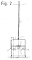
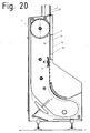
- Fig.1 and Fig.2 each show a side view and a front view of a device according to the invention for separating and aligning position of crown corks and for conveying the isolated and position-oriented crown cork to a (not shown) closing machine.
- the device according to the invention comprises a machine cabinet 1 and a conveyor unit 2 and a movable gravity channel 3, which is provided with an end piece 4 which can be coupled to the (not shown) closing machine.
- Figure 3 Figure 4 and Figure 5 show a sectional view through an inventive device according to section line AA Fig.1 or BB off Fig.2 or CC off Fig.2 so that the machine box 1 is cut.
- This has a simple basic structure of four plastic plates 5a, 5b, 5c, 5d, which are connected by not shown clamping screws and form the framework for all components therein.
- plastic plates 5a, 5b, 5c, 5d also all necessary guides, air ducts, bearing seats, holes, etc. are incorporated.
- a removal conveyor 6 is arranged in the form of a link belt conveyor having a steep conveyor section 6a and a flat conveyor section 6b.
- the steep conveyor section 6a is inclined at an angle> 30 °, preferably> 80 ° to the support plane 7, in FIG Figure 3 that is, inclined in the plane of the drawing or parallel to the plane of the drawing.
- the angle between the flat conveyor section 6b and the level 7 is selected to be ⁇ 10 °.
- the Flat conveyor section 6b can also be parallel to the contact plane, ie horizontally.
- a chamber-like transfer station 8 is arranged, on the one hand by a plane extending parallel to the drawing plane bottom 18 and a parallel to this floor 18, exhaust ports 20 (see Figure 11 ) is limited and on the other hand limited by a lower boundary wall 9 in the direction of gravity and is open via feed openings 10a, 10b in the plastic plates 5b and 5c in the direction of the removal conveyor 6 out.
- a conveyor unit 2 is arranged, which passes through the transfer station 8 and forms a portion of the bottom 18 of the transfer station 8 in a section 2a.
- FIG. 3 Also evident in Figure 3 is a drive device 12 together with transmission gear 47 for the moving parts of the device according to the invention and exhaust openings 14a, 14b in the plastic plates 5a and 5d, which via a blower unit 13 (see Figure 5 ) are supplied with air and this transversely to the conveying direction of the removal conveyor 6 on the members 29 passes.
- the air ducts are incorporated in the plastic plates 5a, 5d.
- a filter pack 34 preferably a high surface filter for sterile air, arranged in the intake of the blower unit 13.
- a differential pressure gauge measures the pressure difference before and after the filter and thus determines the degree of contamination of the filter.
- Figure 4 and Figure 5 in particular also show a task unit 15, in which a bulk material divider 16 is arranged, the preferably automatically brought up crown corks on left and right next to the bulk material divider 16 arranged reservoir 17a, 17b (see also Figure 13 ).
- the bulk material divider 16 is slidably disposed in its holder 27 to the left or right closer to the one or the other reservoir 17a, 17b by means of an adjusting device 28, for example a servomotor or a pneumatic or hydraulic cylinder, to the distribution ratio of abandoned over the task unit 15 crown cork 21 on the two reservoir 17a, 17b and thus to affect the two removal conveyor 6 can.
- an adjusting device 28 for example a servomotor or a pneumatic or hydraulic cylinder
- Figure 6 shows a detailed view of a transfer station 8 without cover 19, which has been omitted for reasons of clarity, and thus exposes the bottom 18 of the transfer station, and a first conveying section 37 of the conveyor unit 2.
- Centrally between the feed openings 10a, 10b can be the portion 2a of the conveyor unit 2, which is embedded in the bottom 18 of the transfer station 8 and thus forms a portion of the bottom 18.
- the crown corks 21 are shown schematically, some of which have already been detected by the conveyor unit 2a and were transported upwards, while others are still collecting in a trough formed by the V-shaped lower boundary wall 9, in particular at the transfer point 50.
- Figure 6 further shows two baffles 22, whose function will be explained later, and two guide elements 23,24, the slightly offset from the conveyor unit recorded crown corks 21 on the conveyor unit 21 center.
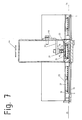
- Figure 7 is a sectional view through an inventive device according to section line DD Figure 6 and shows a view from above into the transfer station 8, that is to say a view of the lower boundary wall 9 of the transfer station 8.
- the distance between the bottom 18 and lid 19 is selected so that the crown corks 21 can not change their position with respect to a reference surface 33, ie. In other words, they can maintain the position they have when entering the transfer station 8 in the direction of the arrows 25 in the transfer station 8 and roll only over its circumference.
- Figure 7 further shows the strand 2b of the conveyor unit 2 and the returning strand 44, both of which run on a forming tube 48 as a conveyor track, preferably made of stainless steel.
- a permanent or electromagnet 26 is arranged, which is formed substantially rod-shaped, with its longitudinal axis parallel to the run 2b extending.
- magnets 26 are arranged behind one another along the section of the conveying unit 2 to be magnetized, in particular of the first conveying section 37 of the conveying unit 2.
- the magnet 26 is surrounded by soft iron elements 49, which are arranged in a U-shape around the magnet 26 in order to guide the magnetic field in the direction of the run 2b.
- the soft iron elements arranged on the side of the magnet 26 are thin-walled, the soft iron element arranged opposite the strand 2b thick-walled in order to produce a narrow magnetic field focused parallel to the strand 2b.
- Magnet 26 and soft iron elements 49 are held by an angle holder 45 which is secured with a slot 46 on the forming tube. About the slot, the distance of the magnet 26th to the upper run and thus the effect of the magnetic field on the crown 2b held on the crown 21 are set.
- Figure 12 shows a partially sectioned detail of the transition between the first 37 and further 38 conveying section of the conveyor unit.
- the magnets 26 are arranged so that their distance to the run 2b of the conveyor unit 2m increases seen in the conveying direction after the transition to reduce the effect of the magnetic field on the strand 2b and thus on the crown cork 21 conveyed thereon.
- Crown corks 21 are given as bulk material on the task unit 15 in the reservoir 17a, 17b.
- the adjustable bulk material divider 16 the distribution of the bulk material to the individual reservoir 17a, 17b are controlled.
- the crown corks 21 are scooped up by the removal conveyors 6 from the storage containers 17a, 17b.
- the removal conveyor 6 with its flat conveyor sections 6b dip into the quantities of crown corks 21 stored in the respective storage containers 17a, 17b.
- the crown corks 21 are thereby arranged by several on the removal conveyors 6, which are designed as a chain belt conveyor, for example, screwed, entrainment elements 30 detected and taken.
- the individual members 29 of the removal conveyor 6 have for this purpose but also for reasons of stability to a bent end portion 31.
- the other end region is in each case formed by a carrier element 30.
- Driving element 30 and alskanteter end portion 31 form a receptacle 32 for the crown cork 21 (see Figure 8 ), with only crown corks as in Figure 8 drawn, so pointing with its visible surface 33 in the direction of the receptacle 32, can be conveyed on the steep conveyor section 6a, since the center of gravity of such entrained crown cork 21 the Thrown out the same from the receptacle 32 prevents.
- crown corks 21 in opposite orientation than this in Figure 8 are shown, so successful with the visible surface 33 of the receptacle 32 come to lie in the receptacle 32, due to the center of gravity and the interpretation of the geometry of the entrainment 30 such entrained crown cork 21 from the removal conveyors 6 only to the steep conveyor section 6 b promoted where They then slip out of the receptacle 32 and again fall back into the respective reservoir 17a, 17b, from which it was taken to be scooped again by the respective removal conveyor 6.
- the crown corks 21 are then conveyed along with this preorientation (reference surface 33 pointing in the direction of the receptacle 32) along the steep conveying section 6a to the level of the charging openings 10a, 10b.
- a blower unit 13 exhaust openings 14a, 14b arranged, whereby in the plastic plates 5a and 5d air transverse to the conveying direction of the removal conveyor 6 is inflatable on the members, such that the crown corks 21, which are held in a preoriented manner in the individual receptacles 32 of the members 29, are blown out into the transfer station 8.
- the blowing out can either take place in rows, or several rows can be blown out together, depending on the arrangement of the openings 14a, 14b.
- the injected air can escape through openings 20 in the lid 19 of the transfer station 8 again.
- a filter pack 34 such as a high surface filter, to keep the air used to blow out the crown corks 21 as sterile as possible and reliably prevent the adhesion of dust or other perturbation elements which could form the basis for subsequent mold growth on the crown cork 21.
- the crown corks 21 fall over the charging openings 10a, 10b into the transfer station 8, by they along the lower boundary wall 9 of the transfer station 8 and along it already located other crown cork 21 (see also Figure 6 ) strive towards the lowest point of the transfer station 8.
- the lowest point of the transfer station 8 is preferably arranged directly above the section 2a of the conveyor unit 2 or more precisely directly above the run 2b of the section 2a of the conveyor unit 2.
- the strand 2b is inserted for this purpose in the bottom 18 of the transfer station 8 or runs in a groove of the same.
- the feeding of the transfer station 8 takes place from both removal conveyors 6.
- the relative position of the two removal conveyors 6 to each other during conveyance is constant and either the carrier elements 30 on the individual links 29 with respect to their vertical distance to the contact surface 7 of the device are always positioned differently or the two feed openings 10a, 10b have a different vertical distance to the contact surface 7 of the device. This ensures that the two removal conveyor 6 never feed the transfer station 8 at the same time, but always slightly offset in time, whereby a mutual obstruction of the charging process is avoided.
- the transfer station 8 further comprises baffle plates 22, which are intended to prevent when loading the transfer station 8 that crown corks 21 are deflected too far from the lower boundary wall 9 of the transfer station 8.
- the distance between the bottom 18 and lid 19 of the transfer station is anyway smaller than the diameter of the crown cork 21 and in practice slightly larger than the thickness, so that a change in position of the crown cork 21 relative to the orientation of the reference surface 33 is not possible.
- the reference surface 33 is the visible surface 33 of the crown cork 21, which must be handled very gently, since this is usually provided with a logo or an inscription and this may not be scratched during the manipulation of the invention or even destroyed.
- the crown corks located in the transfer station 8 take in the course of their residence in the transfer station 8 and a position above (depending on the approach) the section 2b of the conveyor unit 2, where they adhere to the strand 2b due to its magnetization and in the conveying direction 35 of Be conveyed conveyor unit 2.
- baffles 23,24 are provided in the transfer station 8.
- a first conveyor section 2 which is arranged directly after the transfer station 8 and is independent of the transfer station 8, carries at least one conveyor unit 2, which has a conveying direction component pointing away from the contact surface 7 of the device.
- the crown corks 21 are conveyed away after the separation and positional orientation with respect to the support level 7 upwards from the transfer station 8, whereby they can also be placed far below, within reach of operating personnel.
- the conveying section 37 extends vertically, but also inclined courses of the conveying section 37 are conceivable as long as they have a conveying direction component pointing away from the supporting plane 7.
- the device of the invention requires by conveying away the crown cork 21 upwards from the transfer station 8 a small footprint and allows the rapid up-conveying the already isolated and position-oriented crown cork 21 to a height where the further transport can be done horizontally.
- the conveyor unit 2 itself has subsequent to the first conveyor section 37 further conveyor sections or can also be multi-part ie. be constructed of several other conveyor units, depending on the distance to the closing machine.
- the conveyor section 37 is in a defined height, in which a horizontal further transport of the crown cork 21 is possible without disturbing the ground standing systems or from which the crown corks 21 can be optimally supplied to the closing machine, in a further, horizontally extending Conveyor section 38 via.
- the axis of curvature 11 of the transition between the two conveyor sections 37, 38 runs parallel to the surface of the track 2b or reference surface 33 of the crown cork 21 transported on the conveyor unit.
- the transition takes place without deflection rollers and with a large radius, preferably> 200 mm, particularly preferably between 300 mm and 600mm.
- the clamping device 39 for the conveyor unit 2 is arranged at the level of the transfer station 8.
- the distance between the run 2b and the magnets 26 of the conveyor track 48 increases starting with the transition from the conveyor section 37, so that over a majority of the conveyor section 38 no magnetic force acts.
- the gentle decrease of the magnetic force prevents a jam from forming on crown corks 21 at the beginning of the conveying section 38, as would be the case if the magnetic force were suddenly eliminated and crown corks 21 still held by the conveying section 37 are still pushed by magnetic force.
- the horizontally extending conveyor section 38 has a length that extends as a rule to above the closing machine not shown here.
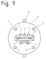
- the conveyor section 38 there goes into a gravity channel 3, which is constructed from a plurality of flanges 40, all of which are connected to each other by the flanges 40 penetrating rods 41 (see Figure 9 ).
- the flanges 40 are additionally arranged on the outside of the same, the flanges 40 interconnecting stiffening profiles 36 with each other connected to additionally stiffen and stabilize the gravity channel 3.
- Each flange 40 is provided with a guide recess 42 within which a guide track 43 for gravity-driven crown corks 21 is held.
- the guide track 43 is formed to protect the reference surface 33 of the crown cork 21 from a good sliding properties having plastic, for example polyethylene (PE) or Teflon (PTFE).
- the 15 to 20 show an alternative embodiment of the invention.
- This alternative embodiment variant is shown with reference to a device for separating and position aligning metallic container closures with only one removal conveyor 6.
- a second removal conveyor according to the embodiment according to Fig.1 to 14 can be provided.
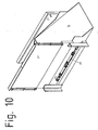
- This alternative embodiment differs from that in the Fig. 1 to 14 embodiment described essentially in that compared to the bottom 18 of the transfer station 8 and with respect to the steep conveyor section 6a of the removal conveyor 6 substantially parallel thereto and therefore forming a kind of top management forming an additional air guide element 52, as in Figure 18 and 19 is shown provided.
- the spoiler 52 thus assumes in the transfer station 8, the functionality of in Figure 7 the cover 19 of the transfer station 8 described above embodiment, ie., That the distance between the bottom 18 and air guide 52 is selected so that the crown corks 21 can not change their position with respect to a reference surface 33, ie. in other words, that they can maintain the position they have when entering the transfer station 8 in the direction of arrow 25 in the transfer station 8 and roll only over its circumference.
- the air guide 52 may be an integral part of the lid 19 or be installed as a separate part that is adjacent to the lid 19 directly.
- the lid 19 does not require exhaust air openings 20 in this case.
- the additional air guide element 52 comprises a cavity 52a which is acted upon by overpressure and has a lateral opening 54, via which the air guide element 52 is supplied with air as blow-out medium via the air guide channel 56 supplying the blow-off openings 14b and incorporated in the plastic plate 5d.
- the air guide element 52 also has gill-like openings / slots 53, which are directed obliquely into the interior of the transfer station 8 in order to convey the crown corks 21 in the direction of run 2b of the conveyor unit 2 (direction of the arrow 25 or transfer point 50), which is a part the rear wall 18 of the transfer station 8 forms.
- Figure 19 is a sectional view along the line KK Figure 16 represents.
- the distribution of the gill-like openings / slots 53 over the width 58 of the air-guiding element 52 is different.
- a first section 55 of the air guide element 52 which is opposite the steep conveyor section 6a of the removal conveyor 6, the arrangement of the gill-like openings / slots 53 is substantially flat, so that they are distributed on the one hand along the entire width 58a of the steep conveyor section 6a of the removal conveyor 6, On the other hand, but also along the height 59 of the steep conveyor section 6 a are distributed, within which the crown cork 21 via the feed openings 10 b in the Transfer station 8 can be blown out or should.
- the distribution of the gill-like openings / slots 53 over the height 59 takes place in such a way that they are distributed over the entire height 59 in the area of the charging opening 10b, but only over a smaller portion along this height in the area of the discharge openings 14b. It is thereby achieved that the crown corks 21 are blown out faster in the region of the charging opening 10b than the crown corks 21 projecting in the rear in the region of the exhaust openings 14b, whereby a crown cork jam can be prevented in a targeted manner.
- the arrangement of the gill-like openings / slots 53 is substantially linear, so that they are distributed along the entire width 58b of the transfer station 8, but at the same time the course the lower boundary wall 9 of the transfer station 8 adjoining the air guiding element 52, offset slightly above it, is distributed along a height 60 which essentially corresponds to the diameter of the crown corks 21.
- the providence of the additional air guiding element 52 causes the crown corks 21 lying in the limbs of the steep conveying section 6a of the removal conveyor 6 to be pushed not only starting from the blowing openings 14b into the transfer station 8, thus forcing one crown cork ahead of the other, but all crown corks of a link the removal conveyor 6 can be pushed out simultaneously.
- the members of the removal conveyor 6 can be made wider and two removal conveyor 6 are replaced by a single removal conveyor 6 with the same width as the total width of the two individual, as in the in the Fig.15 to 20 embodiment shown is the case.
- an additional air guide element 52 in any case contributes to an improvement of the blowout of the crown cork 21 from the removal conveyor 6 independently of whether the device according to the invention two removal conveyor 6, as in the Fig.1 to 14 shown or a removal conveyor 6 as in the Fig.15 to 20 has shown.
- such a spoiler 52 proves to be advantageous in connection with the formation of the lower boundary wall 9 of the transfer station 8 with an elevated transfer point 50 with respect to the remaining areas of the lower boundary wall 9, as shown in FIG Figure 6 is shown in dashed lines, since in this case the crown cork 21 against gravity to the higher transfer point 50 must be transported, which is supported by the additional blow-out of the air guide 52 both in the area of / the removal conveyor 6 and in the transfer station 8, so that it is obvious that an inventive air guide element 52 also in a device as in Fig.1 to 14 shown, can be used.
- a magnetic system 51 is arranged to bind the crown cork 21 in this section more strongly to the members of the removal conveyor 6, to drop the crown cork 21 to prevent this height and to prevent wedging of the crown cork 21 with a arranged in this height before the steep conveyor section 21 cover.
- a magnetic system 51 is arranged to bind the crown cork 21 in this section more strongly to the members of the removal conveyor 6, to drop the crown cork 21 to prevent this height and to prevent wedging of the crown cork 21 with a arranged in this height before the steep conveyor section 21 cover.
Description
Die vorliegende Erfindung bezieht sich auf eine Vorrichtung zum Vereinzeln und Lageausrichten von metallischen Behälterverschlüssen sowie zum Befördern der vereinzelten und lageausgerichteten Behälterverschlüsse, vorzugsweise Kronenkorken, zu einer Weiterverarbeitungsmaschine, vorzugsweise Verschliessmaschine, wobei die Vorrichtung zumindest einen Vorratsbehälter für die Behälterverschlüsse umfasst, sowie zumindest einen Entnahmeförderer zur Entnahme und Vororientierung der Behälterverschlüsse aus dem mindestens einen Vorratsbehälter, wobei der mindestens eine Entnahmeförderer in Betriebsstellung der Vorrichtung einen Steilförderabschnitt aufweist, dessen Förderoberfläche mit der Aufstandsebene einen Winkel > 30°, vorzugsweise > 80° einschließt, sowie zumindest eine, die vereinzelten und lageausgerichteten Behälterverschlüsse zur Verschliessmaschine transportierende Fördereinheit, welche die Behälterverschlüsse mittels einer Auflagefläche an jeweils einer Referenzoberfläche der Behälterverschlüsse kontaktiert, sowie eine Übergabestation, in welche die Behälterverschlüsse quer zur Förderrichtung des mindestens einen Entnahmeförderers vom Steilförderabschnitt ausgeblasen werden und mittels welcher die Behälterverschlüsse vereinzelt und lageorientiert an die Fördereinheit übergeben werden, wobei ein unmittelbar nach der Übergabestation angeordneter erster Förderabschnitt der die vereinzelten und lageausgerichteten Behälterverschlüsse befördernden mindestens einen Fördereinheit eine von der Aufstandsebene der Vorrichtung wegweisende Förderrichtungskomponente aufweist, gemäß dem Oberbegriff des Anspruchs 1.The present invention relates to a device for separating and position aligning metallic container closures and for conveying the isolated and position-aligned container closures, preferably crown corks, to a further processing machine, preferably closing machine, wherein the device comprises at least one reservoir for the container closures, and at least one removal conveyor for Removal and preorientation of the container closures from the at least one storage container, wherein the at least one removal conveyor in the operating position of the device has a steep conveyor section whose conveying surface with the contact plane an angle> 30 °, preferably> 80 ° includes, and at least one, the isolated and position-aligned container closures to the closing machine transporting conveyor unit, which the container closures by means of a support surface at each of a Refe contacting the container closures, and a transfer station, in which the container closures are blown transversely to the conveying direction of the at least one removal conveyor from the steep conveyor section and by means of which the container closures isolated and location-oriented transferred to the conveyor unit, wherein a arranged immediately after the transfer station first conveyor section of the isolated and position-oriented container closures conveying at least one conveyor unit has a conveying direction component pointing away from the support plane of the device, according to the preamble of
Solche Vorrichtungen kommen in Behälterabfüllbetrieben zum Einsatz und dienen der exakten Zuführung der Behälterverschlüsse zu einer Verschliessmaschine, welche die Behälterverschlüsse an den Behältern befestigt, um diese zu verschließen.Such devices are used in Behälterabfüllbetrieben used and serve the exact delivery of the container closures to a Closing machine which attaches the container closures to the containers to close them.
Während frühere Vorrichtungen dieser Art nahezu zur Gänze oberhalb der Verschliessmaschine angeordnet waren, wodurch die Vereinzelung und das Lageausrichten der Behälterverschlüsse praktisch direkt oberhalb der geöffneten, zu verschließenden Behälter stattgefunden hat, ist man in jüngerer Zeit dazu übergegangen, die Vereinzelung und das Lageausrichten der Behälterverschlüsse abseits der Verschliessmaschine durchzuführen, wodurch der bei der Manipulation der Behälterverschlüsse unweigerlich entstehende Abrieb und Staub von den offenen Behältern ferngehalten wird.While earlier devices of this kind were arranged almost entirely above the closing machine, whereby the separation and the positional alignment of the container closures took place practically directly above the opened containers to be closed, the separation and the positional alignment of the container closures has recently been transferred to the side perform the Verschliessmaschine, whereby the inevitable in the manipulation of the container closures abrasion and dust is kept away from the open containers.
Dies führte dazu, dass die bereits vereinzelten und lageausgerichteten Behälterverschlüsse über eine längere Distanz zur Verschliessmaschine befördert werden müssen, wobei die Behälterverschlüsse der Verschliessmaschine in der Regel von oben zugeführt werden, so dass die Behälterverschlüsse nicht nur über eine horizontale Distanz befördert werden müssen sondern auch über eine vertikale Distanz. Übliche Vorrichtungen sind daher so aufgebaut, dass die Behälterverschlüsse am Ort der Aufgabe als unsortiertes bzw. lediglich vorsortiertes Schüttgut zuerst in eine gewisse Höhe transportiert werden und die horizontale Beförderung dann in dieser Höhe zur Verschliessmaschine erfolgt. Dies hat den Vorteil, dass die Aufstandsebene der Vorrichtung als solches sehr klein gehalten werden kann und die horizontale Beförderung der Behälterverschlüsse in der Höhe (übliche Höhen sind in etwa 3m bis 6m) keine wertvolle Standfläche für andere Maschinen belegt, da der unterhalb des in der Höhe verlaufenden Förderweges vorhandene Platz anderweitig genutzt werden kann.This has meant that the already separated and position-aligned container closures must be transported over a longer distance to the closing machine, the container closures of the sealing machine are usually supplied from above, so that the container closures must be transported not only over a horizontal distance but also on a vertical distance. Conventional devices are therefore constructed so that the container closures are transported at the place of the task as unsorted or only presorted bulk goods first in a certain amount and the horizontal carriage then takes place at this level to the closing machine. This has the advantage that the support level of the device as such can be kept very small and the horizontal transport of the container closures in height (usual heights are in about 3m to 6m) no valuable floor space occupied for other machines, since the below in the Height extending conveyor path existing space can be used elsewhere.
Aus der
Auch aus der
Aus der
Es ist daher die Aufgabe der vorliegenden Erfindung eine Vorrichtung zum Vereinzeln und Lageausrichten von metallischen Behälterverschlüssen sowie zum Befördern der vereinzelten und lageausgerichteten Behälterverschlüsse, vorzugsweise Kronenkorken, zu einer Weiterverarbeitungsmaschine, zu schaffen, die diese Nachteile verhindert, wartungsfreundlich ist und einfachen Zugang zu --der Übergabestation ohne Hilfsmittel ermöglicht.It is therefore the object of the present invention to provide an apparatus for separating and position aligning metallic container closures and for conveying the isolated and position-aligned container closures, preferably crown corks, to a further processing machine, which prevents these disadvantages, is easy to maintain and easy access to - der Transfer station without tools allows.
Es ist eine weitere Aufgabe der vorliegenden Erfindung, dabei den bei der Beförderung von metallischen Behälterverschlüssen besonderen Anforderungen hinsichtlich Verbiegen und Zerkratzen Rechnung zu tragen.It is a further object of the present invention to take into account the particular requirements for bending and scratching when transporting metallic container closures.
Erfindungsgemäß wird dies durch die kennzeichnenden Merkmale des Anspruchs 1 erreicht.This is achieved by the characterizing features of
Dabei ist bei einer Vorrichtung zum Vereinzeln und Lageausrichten von metallischen Behälterverschlüssen sowie zum Befördern der vereinzelten und lageausgerichteten Behälterverschlüsse, vorzugsweise Kronenkorken, zu einer Verschliessmaschine, wobei die Vorrichtung zumindest einen Vorratsbehälter und/oder Aufgabeeinheit für die Behälterverschlüsse umfasst, sowie zumindest einen Entnahmeförderer zur Entnahme und Vororientierung der Behälterverschlüsse aus dem mindestens einen Vorratsbehälter, wobei der mindestens eine Entnahmeförderer in Betriebsstellung der Vorrichtung einen Steilförderabschnitt aufweist, dessen Förderoberfläche mit der Aufstandsebene einen Winkel > 30°, vorzugsweise > 80° einschließt, sowie zumindest eine, die vereinzelten und lageausgerichteten Behälterverschlüsse zur Verschliessmaschine transportierende Fördereinheit, welche die Behälterverschlüsse mittels einer Auflagefläche an jeweils einer Referenzoberfläche der Behälterverschlüsse kontaktiert, sowie eine Übergabestation, in welche die Behälterverschlüsse quer zur Förderrichtung des mindestens einen Entnahmeförderers vom Steilförderabschnitt ausgeblasen werden und mittels welcher die Behälterverschlüsse vereinzelt und lageorientiert an die Fördereinheit übergeben werden und wobei ein unmittelbar nach der Übergabestation angeordneter erster Förderabschnitt der die vereinzelten und lageausgerichteten Behälterverschlüsse befördernden Fördereinheit eine von der Aufstandsebene der Vorrichtung wegweisende Förderrichtungskomponente aufweist, vorgesehen, dass die mindestens eine Fördereinheit ein die Behälterverschlüsse förderndes Trum eines endlosen Fördergurtes oder Glieder- oder Plattenbandes umfasst, das entlang einer als Magnetbalken ausgebildeten, permanent- oder elektromagnetischen Förderbahn und - auf dieser zumindest abschnittsweise aufliegend bzw. in geringem Abstand zu dieser geführt ist und die Behälterverschlüsse aus der Übergabestation herausbefördert, wobei die Magnete des Magnetbalkens im wesentlichen stabförmig ausgebildet sind, mit deren Längsachse parallel zum Trum (2b) verlaufend, und wobei die Magnete zur Lenkung des magnetischen Felds in Richtung des Trums U-förmig mit Weicheisenelementen umgeben sind. In this case, in a device for separating and aligning position of metallic container closures and for conveying the isolated and position-aligned container closures, preferably crown corks, to a closing machine, wherein the device comprises at least one reservoir and / or task unit for the container closures, and at least one removal conveyor for removal and Vororientierung the container closures from the at least one reservoir, wherein the at least one removal conveyor in the operating position of the device has a steep conveyor section, the conveying surface with the contact plane an angle> 30 °, preferably> 80 °, and at least one, the isolated and position-aligned container closures for closing machine transporting conveyor unit which kontkont the container closures by means of a support surface on each of a reference surface of the container closures activated, as well as one Transfer station, in which the container closures are blown transversely to the conveying direction of the at least one removal conveyor from the steep conveyor section and by means of which the container closures are separated and transferred position-oriented to the conveyor unit and wherein an immediately after the transfer station arranged first conveyor section of the separated and position-aligned container closures conveying conveyor unit one of The at least one conveying unit comprises a strand of an endless conveyor belt or link or plate belt which promotes the container closures, which runs along a permanent or electromagnetic conveyor track designed as a magnetic bar and / or at least partially resting thereon or on the conveyor belt is guided at a small distance to this and the container closures out of the transfer station, wherein the magnets of the magnetic bar s are formed substantially rod-shaped, with its longitudinal axis parallel to the run (2b) extending, and wherein the magnets for guiding the magnetic field in the direction of the run are U-shaped surrounded with soft iron elements.
Unter dem ersten unmittelbar nach der Übergabestation angeordneten Förderabschnitt, wird jener Bereich der Fördereinheit verstanden, der von der Übergabestation unabhängig ist, dh. auf welchem die Behälterverschlüsse bereits vollkommen vereinzelt und lageorientiert sind und in welchem Förderabschnitt die Förderung der Behälterverschlüsse ausschließlich aufgrund der Förderbewegung der Fördereinheit erfolgt, dh. keine überlagerte Bewegung mit anderen Antrieben erfolgt.Under the first immediately after the transfer station arranged conveyor section, that area of the conveyor unit is understood, which is independent of the transfer station, ie. on which the container closures are already completely isolated and position-oriented and in which conveying section the delivery of the container closures takes place exclusively on the basis of the conveying movement of the delivery unit, ie. no superimposed movement with other drives takes place.
Dadurch wird bewirkt, dass der Entnahmeförderer tatsächlich fast ausschließlich zur Entnahme der Behälterverschlüsse aus dem Vorratsbehälter sowie zur Vororientierung derselben dient, aber nicht eingesetzt wird, um die Behälterverschlüsse über eine nennenswerte Distanz in Richtung zur Verschliessmaschine zu transportieren bzw. um die Behälterverschlüsse in eine bestimmte Höhe zu transportieren, um sie dann in dieser Höhe zu vereinzeln und lageorientiert an die Fördereinheit zu übergeben.As a result, the removal conveyor is actually used almost exclusively to remove the container closures from the storage container and to preorient them, but is not used to transport the container closures over a considerable distance in the direction of the closing machine or around the container closures to a certain height to transport them in order to separate them at this height and handed over situation-oriented to the conveyor unit.
Der Umstand, dass die die Behälterverschlüsse bereits vereinzelt und lageorientiert transportierende mindestens eine Fördereinheit eine von der Aufstandsebene der Vorrichtung wegweisende Förderrichtungskomponente aufweist, bewirkt weiters, dass eine rasche Vereinzelung und Lageorientierung der Behälterverschlüsse, bezogen auf die Aufgabe derselben, erfolgen kann, was in weiterer Folge wiederum dazu führt, dass die Übergabestation, in welcher die Vereinzelung und Lageorientierung der Behälterverschlüsse erfolgt und welche eine erhöhte Störungswahrscheinlichkeit aufweist , bereits in geringer Höhe angeordnet werden kann, die auch ohne Hilfsmittel wie Leitern oder Podeste erreicht werden kann. Unter Übergabestation wird in diesem Zusammenhang jede Art von Abschnitt der Vorrichtung verstanden, in welcher eine Übergabe der unorientierten oder vororientierten Behälterverschlüsse auf eine Fördereinheit erfolgt, auf welcher dann eine Weiterbeförderung der Behälterverschlüsse in vereinzelter und lageorientierter Ausrichtung erfolgt.The fact that the container closures already isolated and position-oriented transporting at least one conveyor unit has a direction away from the contact plane of the device conveying direction component, further causes that a rapid separation and positional orientation of the container closures, based on the task of the same, can be carried out, which in turn leads in turn to the transfer station, in which the separation and position orientation of the container closures takes place and which has an increased probability of disorder, are already arranged at a low altitude can be achieved without tools such as ladders or pedestals. In this context, transfer station is understood to be any type of section of the device in which a transfer of the unoriented or pre-oriented container closures to a delivery unit takes place, on which a further transport of the container closures takes place in an isolated and position-oriented orientation.
Im Zusammenhang mit ferro-metallischen Behälterverschlüssen ergibt sich auf diese Art und Weise eine besonders einfache und sichere Transportmöglichkeit derselben.In the context of ferro-metallic container closures results in this way a particularly simple and secure way to transport the same.
Gemäß einer weiteren bevorzugten Ausführungsvariante der Erfindung ist es vorgesehen, dass ein an den ersten Förderabschnitt anschließender zweiter, in Betriebsstellung der Vorrichtung im wesentlichen horizontal verlaufender Förderabschnitt der mindestens einen Fördereinheit vorgesehen ist, wobei die Krümmungsachse des Übergangs zwischen den beiden Förderabschnitten parallel zur Auflagefläche der Fördereinheit bzw. zur Referenzoberfläche der auf der Fördereinheit transportierten Behälterverschlüsse verläuft und der Übergang vorzugsweise umlenkrollenfrei und mit großem Radius erfolgt. Durch die Umlenkung der Behälterverschlüsse "nach hinten" über deren Referenzoberfläche ist ein sicherer Transport der Behälterverschlüsse möglich. Einerseits wird als Referenzoberfläche eine möglichst große Fläche des Behälterverschlusses gewählt werden, bei Kronenkorken beispielsweise deren Rückseite, so dass diese gut an der magnetischen Fördereinheit haften und andererseits wird aufgrund der Umlenkung "nach hinten" über diese Fläche verhindert, dass sich die Behälterverschlüsse auf der Fördereinheit bewegen können, was einerseits zu unerwünschtem Abrieb führen würde und andererseits aber die Behälterverschlüsse auch optisch beeinträchtigt, was vom Endkunden nicht akzeptiert werden würde.According to a further preferred embodiment variant of the invention, it is provided that a second conveyor section, which extends substantially horizontally in the operating position of the device, is provided at the first conveyor section, the axis of curvature of the transition between the two conveyor sections being parallel to the support surface of the conveyor unit or to the reference surface of the transported on the conveyor unit container closures and the transition is preferably without pulleys and with a large radius. By deflecting the container closures "backwards" over their reference surface, a secure transport of the container closures is possible. On the one hand, the largest possible surface area of the container closure is selected as a reference surface, for example, its back so that they adhere well to the magnetic conveyor unit and on the other hand is prevented due to the deflection "backwards" on this surface, that the container closures on the conveyor unit move, which on the one hand would lead to undesirable abrasion and on the other hand, the container closures also visually impaired, which would not be accepted by the end user.
Der vorzugsweise umlenkrollenfreie Übergang zwischen erstem und zweitem Förderabschnitt der Fördereinheit ermöglicht einerseits eine besonders sanfte Umlenkung und andererseits eine konstante magnetische Haltekraft auch in diesem Umlenkbereich.The preferably deflection roller-free transition between the first and second conveyor section of the conveyor unit allows on the one hand a particularly gentle deflection and on the other hand, a constant magnetic holding force in this deflection.
Gemäß einer weiteren bevorzugten Ausführungsvariante der Erfindung ist es vorgesehen, dass die Übergabestation in einer Höhe gemessen von der Aufstandsebene der Vorrichtung zwischen 1m und 3m, vorzugsweise zwischen 1m und 2m angeordnet ist. Damit befindet sie sich in einer idealen Höhe um ohne Hilfsmittel gewartet bzw. repariert zu werden. Störungen können damit, im Gegensatz zu aus dem Stand der Technik bekannten, gattungsgleichen Vorrichtungen sofort vom Bedienpersonal behoben werden ohne Podest oder Leitern besteigen zu müssen. Auch das für eine möglicherweise erforderliche Reparatur bzw. Wartung notwendige Werkzeug muss nicht auf eine Höhe von 4m bis 6m gehoben werden.According to a further preferred embodiment of the invention, it is provided that the transfer station is arranged at a height measured from the contact plane of the device between 1m and 3m, preferably between 1m and 2m. So she is in an ideal height to be maintained or repaired without aids. Disturbances can thus, in contrast to known from the prior art, generic devices immediately be resolved by the operator without climbing pedestal or ladders. Also, the necessary for a possibly necessary repair or maintenance tool does not need to be raised to a height of 4m to 6m.
In einer weiteren bevorzugten Ausführungsvariante der Erfindung ist es vorgesehen, dass die Übergabestation unmittelbar neben dem mindestens einen Entnahmeförderer angeordnet ist und einen im wesentlichen parallel zum Steilförderabschnitt des Entnahmeförderers angeordneten Boden sowie Deckel umfasst, wobei zumindest eine Beschickungsöffnung vorgesehen ist, über welche die Behälterverschlüsse vom Entnahmeförderer in die Übergabestation beförderbar sind. Durch das Ausbilden der Übergabestation als Kammer ergibt sich der Vorteil, dass bei Bedarf vororientierte Behälterverschlüsse von mehreren Entnahmeförderern in die Übergabestation transportiert werden können. Außerdem ergibt sich durch das Nebeneinanderanordnen von Entnahmeförderer und Übergabestation eine Verringerung der Bauhöhe der Vorrichtung.In a further preferred embodiment of the invention, it is provided that the transfer station is arranged directly adjacent to the at least one removal conveyor and comprises a substantially parallel to the steep conveyor section of the removal conveyor arranged bottom and lid, wherein at least one feed opening is provided, via which the container closures from the removal conveyor can be transported to the transfer station. By forming the transfer station as a chamber, there is the advantage that, if required, pre-oriented container closures can be transported by several removal conveyors into the transfer station. In addition, results from the juxtaposition of removal conveyor and transfer station, a reduction in the height of the device.
Gemäß einer weiteren bevorzugten Ausführungsvariante der Erfindung ist es vorgesehen, dass der Abstand zwischen Boden und Deckel der Übergabestation das seitliche Beschicken der Übergabestation mit Behälterverschlüssen von dem mindestens einen Entnahmeförderer mit Bezug auf deren Referenzfläche lediglich in jener Lage ermöglicht, in welcher die Behälterverschlüsse im Entnahmeförderer transportiert werden. Die Übergabestation bildet somit eine Zwangsführung für die Behälterverschlüsse, so dass diese in die Übergabestation übergeführt werden können, ohne die Vororientierung, die sie durch den Entnahmeförderer aufgezwungen bekommen haben, zu verlieren.According to a further preferred embodiment of the invention, it is provided that the distance between the bottom and lid of the transfer station allows the lateral loading of the transfer station with container closures of the at least one removal conveyor with respect to their reference surface only in that position in which transported the container closures in the removal conveyor become. The transfer station thus forms a positive guide for the container closures, so that they in the transfer station can be transferred without losing the preorientation that they have been forced by the withdrawal conveyor.
In einer weiteren bevorzugten Ausführungsvariante der Erfindung ist es vorgesehen, dass ein Teilabschnitt der mindestens einen Fördereinheit einen Abschnitt des Bodens der Übergabestation bildet, so dass die von dem mindestens einen Entnahmeförderer in die Übergabestation beförderten und vororientierten Behälterverschlüsse abhängig zumindest von der Menge und der Geometrie der Übergabestation dem Zufallsprinzip folgend mit ihrer Referenzoberfläche auf der Fördereinheit zu liegen kommen. Aufgrund des Umstandes dass die Fördereinheit magnetisch ausgebildet ist, kann somit gewährleistet werden, dass die metallischen Behälterverschlüsse von der Fördereinheit aus der Übergabestation weitertransportiert werden, wobei durch geometrische Gestaltung der Übergabestation und/oder durch Stärke, Größe und Anordnung bzw. Gestalt des Magnetfeldes Einfluss auf die Vereinzeltungsleistung der Übergabestation genommen werden kann.In a further preferred embodiment variant of the invention, it is provided that a subsection of the at least one conveyor unit forms a section of the bottom of the transfer station, so that the container closures transported and preoriented by the at least one removal conveyor into the transfer station depend at least on the quantity and geometry of the transfer container Transfer station to come to lie randomly with their reference surface on the conveyor unit. Due to the fact that the delivery unit is formed magnetically, it can thus be ensured that the metallic container closures are transported by the conveyor unit from the transfer station, which influence by geometrical design of the transfer station and / or strength, size and arrangement or shape of the magnetic field the separation performance of the transfer station can be taken.
Um eine reibungslose Übergabe der Behälterverschlüsse an die Fördereinheit zu ermöglichen ist der Übergabepunkt, also jener vorbestimmte Bereich der Übergabestation, an welchem die Behälterverschlüsse von der Fördereinheit jedenfalls zwingend mitgenommen werden, entweder als tiefster oder als höchster Punkt einer in Betriebsstellung der Vorrichtung unteren Begrenzungswand der Übergabestation ausgebildet, die Boden und Deckel der Übergabestation miteinander verbindet.In order to enable a smooth transfer of the container closures to the conveyor unit is the transfer point, ie that predetermined area of the transfer station at which the container closures are necessarily taken by the conveyor unit necessarily, either as the lowest or highest point of a lower operating boundary of the device in the transfer station formed, which connects the bottom and lid of the transfer station together.
Im Falle der Anordnung des Übergabepunktes als in Betriebsposition der Vorrichtung tiefster Punkt der unteren Begrenzungswand, ist dieser in Betriebsposition der Vorrichtung unterhalb der mindestens einen Beschickungsöffnung vorgesehen.In the case of the arrangement of the transfer point as in the operating position of the device lowest point of the lower boundary wall, this is provided in the operating position of the device below the at least one feed opening.
Die aus dem Entnahmeförderer über die Beschickungsöffnung in die Übergabestation beförderten Behälterverschlüsse fallen auf diese Art und Weise in die Übergabestation auf den tiefsten Punkt zu, um dann mittels der Fördereinheit vereinzelt und lageausgerichtet weiterbefördert zu werden.The container closures conveyed from the removal conveyor via the loading opening into the transfer station fall in this way into the transfer station to the lowest point, in order then to be separated by means of the delivery unit and to be conveyed further in a line-aligned manner.
Im Falle der Anordnung des Übergabepunktes als in Betriebsposition der Vorrichtung höchster Punkt der unteren Begrenzungswand kann dieser in Betriebsposition der Vorrichtung sowohl oberhalb als auch unterhalb bzw. auf gleicher Höhe der mindestens einen Beschickungsöffnung angeordnet sein.In the case of the arrangement of the transfer point as in the operating position of the device highest point of the lower boundary wall this can be arranged in the operating position of the device both above and below or at the same height of at least one feed opening.
Sowohl im Fall der Ausbildung des Übergabepunktes als höchster Punkt der unteren Begrenzungswand als auch im Falle der Ausbildung als tiefster Punkt der unteren Begrenzungswand ist der Übergabepunkt jedenfalls über oder vor (je nach Betrachtungsweise) der im Boden der Übergabestation vorgesehenen mindestens einen Fördereinheit positioniert. Diese Ausbildung der unteren Begrenzungswand hat den Vorteil, dass keine Behälterverschlüsse den nach oben erfolgenden Abtransport des von der Fördereinheit zum Abtransport aus der Übergabestation bereits erfassten Behälterverschlusses behindern können.Both in the case of the formation of the transfer point as the highest point of the lower boundary wall and in the case of training as the lowest point of the lower boundary wall of the transfer point is anyway above or before (depending on the approach) provided in the bottom of the transfer station at least one conveyor unit positioned. This embodiment of the lower boundary wall has the advantage that no container closures can obstruct the upward removal of the container closure already detected by the conveyor unit for removal from the transfer station.
Der mindestens eine Entnahmeförderer ist in einer besonders bevorzugten Ausführungsvariante der Erfindung ein, vorzugsweise aus korrosions- und/oder säurebeständigem Stahl gefertigter, endloser Gliederbandförderer mit einem in den Vorratsbehälter eintauchenden Flachförderabschnitt, dessen einzelne Glieder in Förderrichtung gesehen einen ersten Endabschnitt aufweisen, der ein mit einer Fase versehenes Mitnahmeelement trägt, und einen zweiten Endabschnitt, in welchem die Glieder vorzusgsweise aufgekantet ausgebildet sind und der Bereich zwischen dem Mitnahmeelement und der vorzugsweisen Aufkantung zur Aufnahme der Behälterverschlüsse in einer Reihe nebeneinander vorgesehen ist. Die Fertigung des Gliederbandförderers aus korrosions- und/oder säurebeständigem Stahl hat den Vorteil, dass dieser sich statisch nicht auflädt und sehr verschleißfest ist, was insbesondere bei Kronenkorken als Behälterverschlüssen wichtig ist, da diese an der Krone sehr abrasiv wirken. Der Bereich zwischen Mitnahmeelement und Aufkantung kann auf einfache Art und Weise auf die Größe der Behälterverschlüsse abgestimmt werden. Die Gestalt des Mitnahmeelementes ist ideal auf die Form des Behälterverschlusses abgestimmt. Die Verringerung der Neigung des Flachförderabschnittes gegenüber dem Steilförderabschnitt ermöglicht die Erhöhung der Belegungsdichte des Entnahmeförderers.The at least one removal conveyor is in a particularly preferred embodiment of the invention, preferably made of corrosion and / or acid-resistant steel, endless belt conveyor with a dipping into the reservoir flat conveyor section, the individual members seen in the conveying direction having a first end portion of a with a Chamfered driving element carries, and a second end portion, in which the members are vorzusgsweise formed folded and the area between the driving element and the preferred Aufkantung for receiving the container closures in a row next to each other is provided. The production of the link belt conveyor made of corrosion- and / or acid-resistant steel has the advantage that it does not statically charge and is very resistant to wear, which is particularly important for crown caps as container closures, as they act on the crown very abrasive. The area between entrainment element and upstand can be adapted in a simple manner to the size of the container closures. The shape of the entrainment element is ideally matched to the shape of the container closure. The reduction in the inclination of the flat conveyor section relative to the steep conveyor section allows the increase in the occupancy of the extraction conveyor.
Gemäß einer besonders bevorzugten Ausführungsvariante der Erfindung ist es vorgesehen, dass im Bereich der mindestens einen Beschickungsöffnung mindestens eine von einer Gebläseeinheit angesteuerte Ausblasöffnung angeordnet ist, um die Behälterverschlüsse vom mindestens einen Entnahmeförderer reihenweise in die Übergabestation zu befördern. Dabei kann entweder Reihe für Reihe einzeln in die Übergabestation befördert werden oder aber mehrere Reihen gleichzeitig.According to a particularly preferred embodiment of the invention, it is provided that in the region of the at least one feed opening, at least one blow-out opening controlled by a blower unit is arranged in order to convey the container closures from the at least one removal conveyor in rows to the transfer station. It can be transported either row by row individually in the transfer station or several rows simultaneously.
Gleichzeitig kann ein zusätzliches Luftleitelement vorgesehen sein, welches parallel zum Deckel verlaufend, vorzugsweise integraler Bestandteil des Deckels seiend, sowohl zumindest einen Bereich des Steilförderabschnitts als auch zumindest einen Bereich der Übergabestation überdeckend angeordnet ist und in die Übergabestation und/oder auf den Steilabschnitt gerichtete, von einer Gebläseeinheit angesteuerte Öffnungen/Schlitze aufweist, um die Behälterverschlüsse einerseits vom Steilförderabschnitt reihenweise in die Übergabestation zu befördern und andererseits um bereits in der Übergabestation befindliche Behälterverschlüsse in Richtung Übergabepunkt zu befördern.At the same time, an additional air guide element can be provided, which is parallel to the cover, preferably integral part of the cover, both at least a portion of the steep conveyor section and at least a portion of the transfer station is arranged overlapping and directed into the transfer station and / or on the steep section of a blower unit controlled openings / slots, in order to convey the container closures on the one hand from the steep conveyor section in rows in the transfer station and on the other hand to convey already located in the transfer station container closures in the direction of transfer point.
Insbesondere im Zusammenhang mit der Ausbildung des Übergabepunktes als höchsten Punkt der unteren Begrenzungswand der Übergabestation erweist sich das zusätzliche Luftleitelement als vorteilhaft, da in diesem Fall zusätzliche Luftmengen erforderlich sind, um die Behälterverschlüsse entgegen der Schwerkraft zum höher liegenden Übergabepunkt zu befördern.In particular, in connection with the formation of the transfer point as the highest point of the lower boundary wall of the transfer station, the additional air guide proves to be advantageous, since in this case additional amounts of air are required to carry the container closures against gravity to the higher transfer point.
Die Fördergeschwindigkeit der mindestens einen Fördereinheit beträgt in einer weiteren bevorzugten Ausführungsvariante der Erfindung ein Vielfaches der Fördergeschwindigkeit des mindestens einen Entnahmeförderers. Da durch den Ausblasvorgang des mindestens einen Entnahmeförderers stets mehrere Behälterverschlüsse in die Übergabestation fördert, ist es erfindungsgemäß vorgesehen, die mindestens eine Fördereinheit mit höherer Fördergeschwindigkeit zu betreiben, um einen Stau der Behälterverschlüsse in der Übergabestation zu vermeiden.In a further preferred embodiment variant of the invention, the conveying speed of the at least one conveying unit is a multiple of the conveying speed of the at least one removal conveyor. Since a plurality of container closures always conveys into the transfer station by the blow-out process of the at least one removal conveyor, it is provided according to the invention to operate the at least one conveyor unit at a higher conveying speed in order to avoid a jam of the container closures in the transfer station.
Gemäß einer weiteren bevorzugten Ausführungsvariante der Erfindung ist es vorgesehen, dass die Breite des Trums des Förderbandes der mindestens einen Fördereinheit kleiner oder gleich ist als die größte Breite der Behälterverschlüsse. Um zu verhindern, dass versehentlich mehrere Behälterverschlüsse von der mindestens einen Fördereinheit mitgenommen werden und somit keine Vereinzelung im eigentlichen Sinn stattfindet, ist es erforderlich die durch die magnetische Förderbahn zur Verfügung gestellte Haftkraft entsprechend dosiert einzusetzen. Durch die Begrenzung der maximalen Breite des Trums kann einerseits verhindert werden, dass links und rechts neben einem bereits an der Fördereinheit anhaftenden Behälterverschluss weitere Behälterverschlüsse traubenartig an Fördereinheit kleben, andererseits wird dadurch aber auch die Weiterleitung der Magnetkraft durch einen bereits an der Fördereinheit haftenden Behälterverschluss weitgehend unterbunden.According to a further preferred embodiment of the invention, it is provided that the width of the run of the conveyor belt of the at least one conveyor unit is less than or equal to the greatest width of the container closures. In order to prevent that accidentally multiple container closures are taken from the at least one conveyor unit and thus no separation takes place in the true sense, it is necessary to use the provided by the magnetic conveyor path available adhesive force dosed accordingly. By limiting the maximum width of the strand can be prevented on the one hand to the left and right next to an adhering to the conveyor unit container closure more container closures grape-like stick to conveyor unit, on the other hand, but also the forwarding of the magnetic force by an already adhering to the conveyor unit container closure largely prevented.
Gemäß einer weiteren bevorzugten Ausführungsvariante der Erfindung ist es vorgesehen, dass der Steilförderabschnitt des Entnahmeförderers, Boden und Deckel der Übergabestation sowie der erste Förderabschnitt der Fördereinheit senkrecht verlaufend angeordnet sind. Eine solche Anordnung ermöglicht eine in Bezug auf die Aufstandsebene der erfindungsgemäßen Vorrichtung besonders platzsparende Ausführungsvariante.According to a further preferred embodiment of the invention, it is provided that the steep conveyor section of the removal conveyor, bottom and lid of the transfer station and the first conveyor section of the conveyor unit are arranged to extend vertically. Such an arrangement allows a particularly space-saving embodiment variant with respect to the contact plane of the device according to the invention.
Erfindungsgemäß kann es auch vorgesehen sein, dass auf der von den Mitnahmelementen des Steilförderabschnitts abgewandten Seite des mindestens einen Entnahmeförderers ein Magnetsystem angeordnet ist, um die Behälterverschlüsse in diesem Bereich stärker an den Entnahmeförderer zu binden und Verklemmungen durch Herunterfallen zu vermeiden.According to the invention, provision may also be made for a magnet system to be arranged on the side of the at least one removal conveyor which is remote from the entrainment elements of the inclined conveying section, in order to bind the container closures more strongly to the removal conveyor in this area and to avoid deadlocks due to falling.
Als besonders bevorzugte Ausführungsvariante der Erfindung ist es vorgesehen, dass zwei parallel zu einander verlaufende Entnahmeförderer angeordnet sind und die Übergabestation sowie eine die vereinzelten und lageausgerichteten Behälterverschlüsse zur Verschliessmaschine transportierende Fördereinheit zwischen den Entnahmeförderern angeordnet ist, wobei die Übergabestation zwei Beschickungsöffnungen aufweist. Eine solche erfindungsgemäße Vorrichtung hat sich als besonders effizient erwiesen, da die Übergabestation beidseitig beschickt werden kann und die Fördergeschwindigkeiten der Entnahmeförderer sowie der Fördereinheit optimal aufeinander abgestimmt werden können, in dem die Fördergeschwindigkeit der Fördereinheiten langsamer gewählt werden, um das Schöpfen der Behälterverschlüsse aus dem Vorratsbehälter mit optimalen Wirkungsgrad zu ermöglichen und andererseits aber die Fördergeschwindigkeit der Fördereinheit problemlos so gesteigert werden kann, dass die von den Entnahmeförderern in die Übergabestation beförderten Behälterverschlüsse problemlos von der Fördereinheit vereinzelt und lageausgerichtet aus der Übergabestation und weitertransportiert werden können.As a particularly preferred embodiment of the invention, it is provided that two extraction conveyors extending parallel to one another are arranged and the transfer station and a conveyor unit transporting the separated and position-aligned container closures to the closing machine are arranged between the removal conveyors, wherein the transfer station has two charging openings. Such a device according to the invention has proved to be particularly efficient, since the Transfer station can be loaded on both sides and the delivery speeds of the removal conveyor and the conveyor unit can be optimally matched, in which the conveying speed of the conveyor units are selected slower to allow the scooping the container closures from the reservoir with optimum efficiency and on the other hand, the conveying speed of the conveyor unit easily can be increased so that the transported from the removal conveyors in the transfer station container closures easily separated from the conveyor unit and position-aligned from the transfer station and can be transported.
In Bezug auf eine Ausführungsvariante mit zwei Entnahmeförderern sieht eine bevorzugte Ausführungsvariante vor, dass die Relativposition der beiden Entnahmeförderer zueinander während des Förderns konstant ist und entweder die Mitnahmeelemente an den einzelnen Gliedern in Bezug auf deren Vertikalabstand zur Aufstandsebene der Vorrichtung stets unterschiedlich positioniert sind oder die beiden Beschickungsöffnungen einen unterschiedlichen Vertikalabstand zur Aufstandsebene der Vorrichtung aufweisen. Dadurch ist gewährleistet, dass die Beschickung der Übergabestation stets zeitversetzt von den beiden Entnahmeförderern befüllt wird.With regard to a variant embodiment with two removal conveyors, a preferred embodiment provides that the relative position of the two removal conveyors to one another during conveyance is constant and either the entrainment elements on the individual links are always positioned differently with respect to their vertical distance from the contact plane of the device, or both Feed openings have a different vertical distance to the contact plane of the device. This ensures that the feed of the transfer station is always filled with a time delay from the two removal conveyors.
In diesem Fall sieht eine weitere bevorzugte Ausführungsvariante vor, dass die untere Begrenzungswand der Übergabestation V-förmig ausgebildet ist, wobei jeder Schenkel jeweils den tiefsten Punkt einer Beschickungsöffnung mit dem tiefsten Punkt der Übergabestation in Bezug auf die Aufstandsebene verbindet. Die Behälterverschlüsse können so von beiden Seiten in die Übergabestation fallen und werden automatisch auf die mittig angeordnete Fördereinheit gelenkt.In this case, a further preferred embodiment provides that the lower boundary wall of the transfer station is V-shaped, wherein each leg connects in each case the lowest point of a feed opening with the lowest point of the transfer station with respect to the contact plane. The container closures can thus fall from both sides in the transfer station and are automatically directed to the centrally located conveyor unit.
In einer weiteren bevorzugten Ausführungsvariante der Erfindung ist es vorgesehen, dass zwischen den beiden Entnahmeförderern und in Betriebsstellung der Vorrichtung unterhalb der Übergabestation eine Aufgabeeinheit vorgesehen ist, welche einen vorzugsweise keilförmigen Schüttgutteiler aufweist, der die zu vereinzelnden und lageauszurichtend einer Verschließmaschine zuzuführenden Behälterverschlüsse auf die beiden Entnahmeförderer aufteilt. Die Behälterverschlüsse können dadurch automatisiert der erfindungsgemäßen Vorrichtung zugeführt werden, die Aufteilung auf die beiden Entnahmeförderer erfolgt dann mittels des Schüttgutteilers, der in einer besonders bevorzugten Ausführungsvariante der Erfindung zwischen den Entnahmeförderern beweglich angeordnet ist, um nicht nur aber auch unter dem Strom der von außerhalb der Vorrichtung zugeführten Behälterverschlüsse das Aufteilungsverhältnis der aufgegebenen Behälterverschlüsse auf die beiden Entnahmeförderer beeinflussen zu können.In a further preferred embodiment of the invention, it is provided that a task unit is provided between the two removal conveyors and in the operating position of the device below the transfer station, which has a preferably wedge-shaped bulk material divider, the container to be separated and warehousing a closure machine to be supplied container closures on the two removal conveyor divides. The container closures can be automated by the The device according to the invention are then fed to the two removal conveyors by means of the bulk material divider, which is arranged in a particularly preferred embodiment of the invention between the removal conveyors to not only but also under the flow of supplied from outside the device container closures, the distribution ratio of abandoned container closures on the two removal conveyor to influence.
Gemäß einer weiteren bevorzugten Ausführungsvariante der Erfindung ist es vorgesehen, dass zwischen Fördereinheit und Weiterverarbeitungsmaschine eine Schwerkraftrinne angeordnet ist, welche eine Führungsbahn aufweist, auf welcher die Behälterverschlüsse aufgrund der Schwerkraft in Richtung zur Weiterverarbeitungsmaschine rutschen und die Führungsbahn aus Kunststoff, vorzugsweise Polyethylen ausgebildet ist bzw. mit einem aus Kunststoff, vorzugsweise Polyethylen aufgebauten Belag zumindest im Kontaktbereich mit den Behälterverschlüssen versehen ist. Dadurch werden die Behälterverschlüsse während ihres Falls in Richtung Weiterverarbeitungsmaschine geschont, was insbesondere bei Kronenkorken als Behälterverschlüsse sehr wichtig ist, da diese auf ihrer Sichtfläche keine Verschleißerscheinungen aufweisen dürfen.According to a further preferred embodiment of the invention, it is provided that between the conveyor unit and further processing machine, a gravity channel is arranged, which has a guide track on which the container closures slip due to gravity in the direction of the further processing machine and the guide track is made of plastic, preferably polyethylene or is provided with a made of plastic, preferably polyethylene covering at least in the contact area with the container closures. As a result, the container closures are spared during their fall in the direction of further processing machine, which is very important especially as crown caps as container closures, as they must have no signs of wear on their visible surface.
Im Anschluss erfolgt nun eine detaillierte Beschreibung der Erfindung anhand eines Ausführungsbeispiels, nämlich einer Vorrichtung zum Vereinzeln und Lageausrichten von Kronenkorken, sowie zum Befördern der vereinzelten und lageausgerichteten Kronenkorken, zu einer Verschliessmaschine.Following is a detailed description of the invention with reference to an embodiment, namely a device for separating and aligning position of crown corks, as well as for conveying the isolated and position-oriented crown cork, to a closing machine.
Dabei zeigt:
- Fig.1
- eine Seitenansicht einer erfindungsgemäßen Vorrichtung
- Fig.2
- eine Frontansicht einer erfindungsgemäßen Vorrichtung
- Fig.3
- eine Schnittansicht durch eine erfindungsgemäße Vorrichtung gemäß Schnittlinie AA aus
Fig.1 - Fig.4
- eine Schnittansicht durch eine erfindungsgemäße Vorrichtung gemäß Schnittlinie BB aus
Fig.2 - Fig.5
- eine Schnittansicht durch eine erfindungsgemäße Vorrichtung gemäß Schnittlinie CC aus
Fig.2 - Fig.6
- eine Detailansicht der Übergabestation
- Fig.7
- eine Schnittansicht durch eine erfindungsgemäße Vorrichtung gemäß Schnittlinie DD aus
Fig.6 - Fig.8
- eine Schnittansicht eines Details des Entnahmeförderers
- Fig.9
- eine Schnittansicht durch die Schwerkraftrinne
- Fig.10
- eine Detailansicht des verstellbaren Schüttgutteilers
- Fig.11
- eine Detailansicht des Deckels der Übergabestation
- Fig.12
- eine teilweise geschnittene Detailansicht des Übergangs zwischen erstem und weiterem Förderabschnitt der Fördereinheit
- Fig.13
- eine Draufsicht auf eine Erfindungsgemäße Vorrichtung
- Fig.14
- einen Schnitt durch die Übergabestation gemäß Schnittlinie EJ aus
Fig.3 - Fig.15
- eine Frontansicht einer alternativen Ausführungsvariante der erfindungsgemäßen Vorrichtung
- Fig.16
- eine Seitenansicht der alternativen Ausführungsvariante der erfindungsgemäßen Vorrichtung
- Fig.17
- eine Schnittansicht durch die alternative Ausführungsvariante der erfindungsgemäßen Vorrichtung gemäß Schnittlinie AA aus
Fig.16 - Fig.18
- eine Schnittansicht durch die alternative Ausführungsvariante der Erfindung gemäß Schnittlinie LL aus
Fig.17 - Fig.19
- eine Schnittansicht durch die alternative Ausführungsvariante der Erfindung gemäß Schnittlinie KK aus
Fig.16 - Fig.20
- eine Schnittansicht durch eine alternative Ausführungsvariante der Erfindung gemäß Schnittlinie MM aus
Fig.15
- Fig.1
- a side view of a device according to the invention
- Fig.2
- a front view of a device according to the invention
- Figure 3
- a sectional view through an inventive device according to section line AA
Fig.1 - Figure 4
- a sectional view through an inventive device according to section line BB
Fig.2 - Figure 5
- a sectional view through an inventive device according to section line CC
Fig.2 - Figure 6
- a detailed view of the transfer station
- Figure 7
- a sectional view through an inventive device according to section line DD
Figure 6 - Figure 8
- a sectional view of a detail of the removal conveyor
- Figure 9
- a sectional view through the gravity groove
- Figure 10
- a detailed view of the adjustable bulk material divider
- Figure 11
- a detailed view of the lid of the transfer station
- Figure 12
- a partially sectioned detailed view of the transition between the first and further conveying section of the conveyor unit
- Figure 13
- a plan view of an inventive device
- Figure 14
- a section through the transfer station according to section line EJ
Figure 3 - Figure 15
- a front view of an alternative embodiment of the device according to the invention
- Figure 16
- a side view of the alternative embodiment of the device according to the invention
- Figure 17
- a sectional view through the alternative embodiment of the device according to the invention according to section line AA
Figure 16 - Figure 18
- a sectional view through the alternative embodiment of the invention according to section line LL
Figure 17 - Figure 19
- a sectional view through the alternative embodiment of the invention according to section line KK
Figure 16 - fig.20
- a sectional view through an alternative embodiment of the invention according to section line MM
Figure 15
Zwischen den Kunststoffplatten 5a und 5b sowie 5c und 5d ist jeweils ein Entnahmeförderer 6 in Form eines Gliederbandförderers angeordnet, der einen Steilförderabschnitt 6a und einen Flachförderabschnitt 6b aufweist. Der Steilförderabschnitt 6a ist dabei in einem Winkel > 30°, vorzugsweise > 80° zur Aufstandsebene 7 geneigt, in
Für den Fachmann offensichtlich ist, dass die Anordnung von zwei Entnahmeförderern rein beispielhaft ist und eine die Vorteile der Erfindung aufweisende Vorrichtung zum Vereinzeln und Lageausrichtung von Behälterverschlüssen auch nur einen Entnahmeförderer, bei sonst im wesentlichen gleichen Aufbau, wie später noch beschrieben, aufweisen kann.It is obvious to a person skilled in the art that the arrangement of two removal conveyors is purely exemplary and a device for separating and aligning container closures having the advantages of the invention can also have only one removal conveyor, otherwise of essentially the same construction as described later.
Mittig zwischen den beiden Entnahmeförderern und zwischen den Kunststoffplatten 5b und 5c ist eine kammerartige Übergabestation 8 angeordnet, die einerseits von einem parallel zur Zeichenebene verlaufenden Boden 18 und einem parallel zu diesem Boden 18 verlaufenden, Abluftöffnungen 20 (siehe
Ebenfalls mittig zwischen den Entnahmeförderern 6 ist eine Fördereinheit 2 angeordnet, die durch die Übergabestation 8 verläuft und in einem Teilabschnitt 2a einen Abschnitt des Bodens 18 der Übergabestation 8 bildet.Also centrally between the
Ebenfalls ersichtlich in
Im Ansaugweg der Gebläseeinheit 13 ist ein Filterpaket 34, vorzugsweise ein Hochoberflächenfilter für Sterilluft, angeordnet. Ein Differenzdruckmanometer misst den Druckunterschied vor und nach dem Filter und bestimmt so den Verschmutzungsgrad des Filters.In the intake of the
Die Kronenkorken 21 sind schematisch dargestellt, wobei einige bereits von der Fördereinheit 2a erfasst wurden und nach oben transportiert wurden, andere wiederum sich noch in einer von der V-förmigen unteren Begrenzungswand 9 gebildeten Mulde, insbesondere am Übergabepunkt 50 sammeln.The crown corks 21 are shown schematically, some of which have already been detected by the
Während die in
Sehr gut kann man in dieser Ansicht erkennen, dass der Abstand zwischen Boden 18 und Deckel 19 so gewählt ist, dass die Kronenkorken 21 ihre Lage mit Bezug auf eine Referenzfläche 33 nicht mehr ändern können, dh. mit anderen Worten, dass sie jene Lage, die sie beim Eintritt in die Übergabestation 8 in Richtung der Pfeile 25 aufweisen auch in der Übergabestation 8 beibehalten und lediglich über ihren Umfang abrollen können.Very well, it can be seen in this view that the distance between the bottom 18 and
Magnet 26 und Weicheisenelemente 49 sind dabei von einem Winkelhalter 45 gehalten, der mit einem Langloch 46 am Formrohr befestigt ist. Über das Langloch kann der Abstand des Magneten 26 zum oberen Trum und damit die Wirkung des magnetischen Felds auf die am Trum 2b gehaltenen Kronenkorken 21 eingestellt werden.
Im Anschluss erfolgt nun eine detaillierte Beschreibung der Funktionsweise der erfindungsgemäßen Vorrichtung.Following is now a detailed description of the operation of the device according to the invention.
Kronenkorken 21 werden als Schüttgut über die Aufgabeeinheit 15 in die Vorratsbehälter 17a,17b aufgegeben. Über den verstellbaren Schüttgutteiler 16 kann die Aufteilung des Schüttguts auf die einzelnen Vorratsbehälter 17a,17b gesteuert werden.Crown corks 21 are given as bulk material on the
In weiterer Folge werden die Kronenkorken 21 von den Entnahmeförderern 6 aus den Vorratsbehältern 17a,17b geschöpft. Zu diesem Zweck tauchen die Entnahmeförderer 6 mit ihren Flachförderabschnitten 6b in die in den jeweiligen Vorratsbehältern 17a,17b gespeicherten Mengen aus Kronenkorken 21 ein. Die Kronenkorken 21 werden dabei von mehreren an den Entnahmeförderern 6, die als Gliederbandförderer ausgebildet sind, angeordneten, beispielsweise verschraubten, Mitnahmeelementen 30 erfasst und mitgenommen. Die einzelnen Glieder 29 der Entnahmeförderer 6 weisen zu diesem Zweck aber auch aus Stabilitätsgründen einen aufgekanteten Endbereich 31 auf. Der andere Endbereich wird jeweils von einem Mitnahmeelement 30 gebildet. Mitnahmeelement 30 und aufgekanteter Endbereich 31 bilden eine Aufnahme 32 für die Kronenkorken 21 (siehe
In den Entnahmeförderern 6 werden die Kronenkorken 21 dann mit dieser Vororientierung (Referenzfläche 33 in Richtung der Aufnahme 32 weisend) den Steilförderabschnitt 6a entlangbefördert bis auf die Höhe der Beschickungsöffnungen 10a,10b. Jeweils auf der gegenüberliegenden Seite der Beschickungsöffnungen 10a,10b in Bezug auf den jeweiligen Steilförderabschnitt 6a sind von einer Gebläseeinheit 13 angesteuerte Ausblasöffnungen 14a,14b angeordnet, wodurch in den Kunststoffplatten 5a bzw. 5d Luft quer zur Förderrichtung der Entnahmeförderer 6 auf dessen Glieder einblasbar ist, so dass die in den einzelnen Aufnahmen 32 der Glieder 29 vororientiert gehaltenen Kronenkorken 21 in die Übergabestation 8 ausgeblasen werden. Das Ausblasen kann dabei entweder reihenweise erfolgen, oder aber können mehrere Reihen gemeinsam ausgeblasen werden, abhängig von der Anordnung der Öffnungen 14a,14b. Die eingeblasene Luft kann über Öffnungen 20 im Deckel 19 der Übergabestation 8 wieder entweichen.In the
Den Gebläseeinheiten vorgeschalten ist ein Filterpaket 34, beispielsweise ein Hochoberflächenfilter, um die zum Ausblasen der Kronenkorken 21 verwendete Luft möglichst steril zu halten und das Anhaften von Staub oder anderen Störelementen, welche die Basis für spätere Schimmelbildung an den Kronenkorken 21 bilden könnte, verlässlich auszuschließen.Upstream of the blower units is a
In weiterer Folge, nach dem Ausblasen der Kronenkorken 21 aus den Aufnahmen 32 der Entnahmeförderer 6 fallen die Kronenkorken 21 über die Beschickungsöffnungen 10a,10b in die Übergabestation 8, indem sie entlang der unteren Begrenzungswand 9 der Übergabestation 8 bzw. entlang darauf bereits befindlichen anderen Kronenkorken 21 (siehe auch
Die Beschickung der Übergabestation 8 erfolgt von beiden Entnahmeförderern 6 aus. Um zu verhindern, dass die Übergabestation gleichzeitig von beiden Entnahmeförderern 6 beschickt wird und sich möglicherweise gegenseitig stören, ist es vorgesehen, dass die Relativposition der beiden Entnahmeförderer 6 zueinander während des Förderns konstant ist und entweder die Mitnahmeelemente 30 an den einzelnen Gliedern 29 in Bezug auf deren Vertikalabstand zur Aufstandsebene 7 der Vorrichtung stets unterschiedlich positioniert sind oder die beiden Beschickungsöffnungen 10a,10b einen unterschiedlichen Vertikalabstand zur Aufstandsebene 7 der Vorrichtung aufweisen. Dadurch ist gewährleistet, dass die beiden Entnahmeförderer 6 die Übergabestation 8 nie gleichzeitig beschicken, sondern stets etwas zeitversetzt, wodurch eine gegenseitige Behinderung des Beschickungsvorganges vermieden wird.The feeding of the
Die Übergabestation 8 weist des weiteren Prallplatten 22 auf, die beim Beschicken der Übergabestation 8 verhindern sollen, dass Kronenkorken 21 zu weit von der unteren Begrenzungswand 9 der Übergabestation 8 abgelenkt werden.The
Der Abstand zwischen Boden 18 und Deckel 19 der Übergabestation ist jedenfalls kleiner als der Durchmesser der Kronenkorken 21 und in der Praxis etwas größer als deren Dicke, so dass eine Lageveränderung der Kronenkorken 21 bezogen auf deren Orientierung der Referenzfläche 33 nicht möglich ist. Bei der Referenzfläche 33 handelt es sich um die Sichtfläche 33 der Kronenkorken 21, die besonders schonend gehandhabt werden muss, da diese in der Regel mit einem Logo oder einer Aufschrift versehen ist und diese während der erfindungsgemäßen Manipulation nicht zerkratzt oder gar zerstört werden darf.The distance between the bottom 18 and
Die in der Übergabestation 8 befindlichen Kronenkorken 21 nehmen im Lauf ihrer Verweildauer in der Übergabestation 8 auch eine Position über oder vor (je nach Betrachtungsweise) dem Teilabschnitt 2b der Fördereinheit 2 ein, wo sie am Trum 2b aufgrund dessen Magnetisierung anhaften und in Förderrichtung 35 der Fördereinheit 2 weiterbefördert werden. Zum Zentrieren der Kronenkorken 21 auf dem Trum 2b sind in der Übergabestation 8 auch Leitbleche 23,24 vorgesehen.The crown corks located in the
Erfindungsgemäß ist ein unmittelbar nach der Übergabestation 8 angeordneter erster, von der Übergabestation 8 unabhängiger Förderabschnitt 37 der die vereinzelten und lageausgerichteten Behälterverschlüsse befördernden mindestens einen Fördereinheit 2 vorgesehen, der eine von der Aufstandsebene 7 der Vorrichtung wegweisende Förderrichtungskomponente aufweist. Mit anderen Worten werden die Kronenkorken 21 nach deren Vereinzelung und Lageorientierung in Bezug auf die Aufstandsebene 7 nach oben von der Übergabestation 8 wegbefördert, wodurch diese auch weit unten, in Griffweite für Bedienpersonal angeordnet werden kann. Im vorliegenden Ausführungsbeispiel verläuft der Förderabschnitt 37 vertikal, allerdings sind auch geneigte Verläufe des Förderabschnitts 37 denkbar, solange sie eine von der Aufstandsebene 7 wegweisende Förderrichtungskomponente aufweisen. Die erfindungsgemäße Vorrichtung benötigt durch das Wegfördern der Kronenkorken 21 nach oben von der Übergabestation 8 eine geringe Grundfläche und ermöglicht das rasche Hochfördern der bereits vereinzelten und lageausgerichteten Kronenkorken 21 auf eine Höhe, wo der Weitertransport horizontal erfolgen kann.According to the invention, a
Unter dem Begriff "von der Übergabestation unabhängig" wird in diesem Zusammenhang verstanden, dass die Übergabe an die Fördereinheit 2 in diesem Förderabschnitt 37 bereits vollkommen beendet sein muss, dh. dass die Kronenkorken 21 in diesem unmittelbar an die Übergabestation 8 grenzenden ersten Förderabschnitt 37 der Fördereinheit 2 bereits vollkommen vereinzelt, lageorientiert und ausgerichtet sind, wobei eine Zentrierung der Kronenkorken 21 auf dem Trum 2b auch in einem späteren Abschnitt erfolgen kann, da eine Zentrierung an der prinzipiellen Vereinzelung bzw. Lageausrichtung nichts mehr ändert.The term "independent of the transfer station" is understood in this context that the transfer to the
Die Förderung der Kronenkorken in diesem Förderabschnitt 37 beruht ausschließlich auf der Förderbewegung der Fördereinheit 2.The promotion of crown corks in this
Die Fördereinheit 2 selbst hat nachfolgend dem ersten Förderabschnitt 37 weitere Förderabschnitte bzw. kann auch mehrteilig dh. aus mehreren anderen Fördereinheiten aufgebaut sein, je nach Distanz zur Verschliessmaschine. Im vorliegenden Fall geht der Förderabschnitt 37 in einer definierten Höhe, in welcher ein horizontaler Weitertransport der Kronenkorken 21 möglich ist, ohne am Boden stehende Anlagen zu stören bzw. aus welcher die Kronenkorken 21 optimal der Verschliessmaschine zugeführt werden können, in einen weiteren, horizontal verlaufenden Förderabschnitt 38 über. Die Krümmungsachse 11 des Übergangs zwischen den beiden Förderabschnitten 37,38 verläuft parallel zur Oberfläche des Trums 2b bzw. zur Referenzoberfläche 33 der auf der Fördereinheit transportierten Kronenkorken 21. Der Übergang erfolgt ohne Umlenkrollen und mit großem Radius, vorzugsweise > 200mm, besonders bevorzugt zwischen 300mm und 600mm. Die Spannvorrichtung 39 für die Fördereinheit 2 ist auf Höhe der Übergabestation 8 angeordnet.The
Im Förderabschnitt 38 vergrößert sich der Abstand zwischen Trum 2b und den Magneten 26 der Förderbahn 48 beginnend mit dem Übergang vom Förderabschnitt 37, so dass über einen Großteil des Förderabschnittes 38 keine Magnetkraft wirkt. Das sanfte Verringern der Magnetkraft verhindert, dass sich zu Beginn des Förderabschnitts 38 ein Stau an Kronenkorken 21 bildet, wie es der Fall wäre, wenn die Magnetkraft plötzlich wegbliebe und aus dem Förderabschnitt 37 aber noch von Magnetkraft gehaltene Kronenkorken 21 nachgeschoben werden.In the
Der horizontal verlaufende Förderabschnitt 38 weist eine Länge auf, die in der Regel bis oberhalb der hier nicht gezeichneten Verschliessmaschine reicht. Der Förderabschnitt 38 geht dort in eine Schwerkraftrinne 3 über, die aus mehreren Flanschen 40 aufgebaut ist, die allesamt durch die Flansche 40 durchdringende Stäbe 41 miteinander verbunden sind (siehe
Jeder Flansch 40 ist mit einer Führungsausnehmung 42 versehen, innerhalb welcher eine Führungsbahn 43 für aufgrund der Schwerkraft nach unten beförderte Kronenkorken 21 gehalten ist. Die Führungsbahn 43 ist zur Schonung der Referenzoberfläche 33 der Kronenkorken 21 aus einem gute Gleiteigenschaften aufweisenden Kunststoff gebildet, beispielsweise Polyethylen (PE) oder Teflon (PTFE).Each
Die
Diese alternative Ausführungsvariante unterscheidet sich von der in den
Das Luftleitelement 52 kann dabei integraler Bestandteil des Deckels 19 sein oder aber als separater Teil verbaut werden, das unmittelbar an den Deckel 19 angrenzt. Der Deckel 19 benötigt in diesem Fall keine Abluftöffnungen 20.The
Das zusätzliche Luftleitelement 52 umfasst einen mit Überdruck beaufschlagten Hohlraum 52a mit einer seitlichen Öffnung 54, über welche das Luftleitelement 52 über den die Ausblasöffnungen 14b versorgenden, in der Kunststoffplatte 5d eingearbeiteten Luftführkanal 56 mit Luft als Ausblasmedium versorgt wird.The additional
Das Luftleitelement 52 weist außerdem kiemenartige Öffnungen/Schlitze 53 auf, die schräg in das Innere der Übergabestation 8 gerichtet sind, um die Kronenkorken 21 in Richtung Trum 2b der Fördereinheit 2 (Richtung des Pfeiles 25 bzw. Übergabepunkt 50) zu befördern, das einen Teil der Rückwand 18 der Übergabestation 8 bildet.The
Somit werden die Kronenkorken 21 nicht nur über die Ausblasöffnungen 14b aus den Gliedern des Entnahmeförderers 6 ausgeblasen, sondern erfahren einen zusätzlichen Ausblasimpuls durch die kiemenartigen Öffnungen/Schlitze 53 des Luftleitelementes 52 sowohl im Bereich des Entnahmeförderers als auch im Bereich der Übergabestation.Thus, not only are the crown corks 21 blown out of the members of the
Dieser Umstand ist auch sehr gut aus
In einem ersten Abschnitt 55 des Luftleitelementes 52, der dem Steilförderabschnitt 6a des Entnahmeförderers 6 gegenüberliegt, erfolgt die Anordnung der kiemenartigen Öffnungen/Schlitze 53 im wesentlichen flächig, so dass diese einerseits entlang der gesamten Breite 58a des Steilförderabschnitts 6a des Entnahmeförderers 6 verteilt angeordnet sind, andererseits aber auch entlang jener Höhe 59 des Steilförderabschnitts 6a verteilt sind, innerhalb welcher die Kronenkorken 21 über die Beschickungsöffnungen 10b in die Übergabestation 8 ausgeblasen werden können bzw. sollen. Die Verteilung der kiemenartigen Öffnungen/Schlitze 53 über die Höhe 59 erfolgt dabei so, dass sie im Bereich der Beschickungsöffnung 10b über die gesamte Höhe 59 verteilt angeordnet sind, im Bereich der Ausblasöffnungen 14b jedoch nur über einen geringeren Abschnitt entlang dieser Höhe. Dadurch wird erreicht, dass die Kronenkorken 21 im Bereich der Beschickungsöffnung 10b schneller ausgeblasen werden, als die hinten anstehenden Kronenkorken 21 im Bereich der Ausblasöffnungen 14b, wodurch ein Kronenkorkenstau zielführend verhindert werden kann.In a
In einem zweiten Abschnitt 57 des Luftleitelementes 52, der dem Boden 18 der Übergabestation 8 gegenüberliegt, erfolgt die Anordnung der kiemenartigen Öffnungen/Schlitze 53 im wesentlichen linienförmig, so dass diese entlang der gesamten Breite 58b der Übergabestation 8 verteilt angeordnet sind, jedoch gleichzeitig dem Verlauf der an das Luftleitelement 52 angrenzenden unteren Begrenzungswand 9 der Übergabestation 8, leicht oberhalb versetzt, folgend, entlang einer Höhe 60 verteilt, die im wesentlichen dem Durchmesser der Kronenkorken 21 entspricht.In a
Die Vorsehung des zusätzlichen Luftleitelementes 52 bewirkt, dass die in den Gliedern des Steilförderabschnitts 6a des Entnahmeförderers 6 liegenden Kronenkorken 21 nicht nur beginnend von den Ausblasöffnungen 14b in die Übergabestation 8 ausgeschoben werden, somit ein Kronenkorken den anderen vor sich herschiebend, sondern alle Kronenkorken eines Gliedes des Entnahmeförderers 6 gleichzeitig ausgeschoben werden können.The providence of the additional
Durch diese verbesserte Ausblasung der Kronenkorken 21 in die Übergabestation 8, können die Glieder des Entnahmeförderers 6 breiter ausgeführt werden und zwei Entnahmeförderer 6 durch einen einzigen Entnahmeförderer 6 mit der gleichen Breite wie die Gesamtbreite der beiden einzelnen ersetzt werden, wie dies im in den
Es sei an dieser Stelle jedoch erwähnt, dass ein zusätzliches Luftleitelement 52 jedenfalls zu einer Verbesserung der Ausblasung der Kronenkorken 21 vom Entnahmeförderer 6 beiträgt unabhängig davon, ob die erfindungsgemäße Vorrichtung zwei Entnahmeförderer 6, wie in den
Im Falle der Ausführung der erfindungsgemäßen Vorrichtung mit nur einem Entnahmeförderer 6, wie dies in den
Zu diesem Zweck bietet sich an, die den Ausblasöffnungen 14b gegenüberliegenden Seite 61 der Übergabestation 8 mit der Saugseite der Gebläseeinheit 13 zu verbinden und die Ausblasöffnungen 14b bzw. den Luftführkanal 56 und damit den Hohlraum 52a mit der Druckseite der Gebläseeinheit 13 wodurch der in
Weiters kann sowohl bei der Ausführungsvariante gemäß
Rein beispielhaft sind Entnahmeförderer 6 und Fördereinheit 2 in dem Ausführungsbeispiel nach den
Claims (22)
- Device for separation and position alignment of metallic container closures (21), as well as for conveying the separated and position-aligned container closures (21), preferably crown corks, to a further processing machine, preferably sealing machine, the device comprising- at least one supply container (17a, 17b) and/or application unit (15) for the container closures (21),- at least one removal conveyor (6) for removal and preorientation of the container closures (21) from the at least one supply container (17a, 17b), whereby the at least one removal conveyor (6) has a steep conveying section (6a) in the operating position of the device, the conveying surface of which section encloses an angle > 30°, preferably > 80°, with the support plane, as well as- at least one conveying unit (2) that transports the separated and position-aligned container closures (21) to the further processing machine and contacts the container closures (21) by means of a contact surface (2b), at a reference surface (33) of the container closures, in each instance,- as well as a transfer station (8) in which the container closures are blown out from the steep conveying section (6a) transverse to the conveying direction of the at least one removal conveyor (6), and by means of which station the container closures (21) are passed on to the conveying unit (2) in separated and position-oriented manner,- whereby a first conveying section (37) of the at least one conveying unit (2) that conveys the separated and position-oriented container closures (21), disposed directly behind the transfer station (8), has a conveying direction component that faces away from the support plane (7) of the device, characterized in that the at least one conveying unit (2) comprises a run (2b) of an endless conveyor belt or link belt or plate belt, which conveys the container closures (21), is guided along a permanently magnetic or electromagnetic conveyor track configured as a magnetic bar, lying on this track at least in sections, or at a slight distance from it, and conveys the container closures (21) out of the transfer station (8), the magnets (26) of the magnetic bar being configured essentially in bar shape with their longitudinal axis running parallel to the run (2b), and with the magnets (26) being surrounded by soft iron elements (49)in a U-shaped manner for guiding the magnetic field towards the run (2b).
- Device according to claim 1, characterized in that a second conveying section (38) of the at least one conveying unit (2), following the first conveying section (37), running essentially horizontal in the operating position of the device, is provided, whereby the curvature axis (11) of the transition between the two conveying sections (37, 38) runs parallel to the contact surface (2b) of the conveying unit (2) or to the reference surface (33) of the container closures (21) transported on the conveying unit (2), and the transition preferably takes place in deflection-roller-free manner.
- Device according to one of claims 1 to 2, characterized in that the transfer station (8) is disposed at a height, measured from the support plane (7) of the device, between 1 m and 3 m, preferably between 1 m and 2 m.
- Device according to one of claims 1 to 3, characterized in that the transfer station (8) is disposed directly next to the at least one removal conveyor (6) and comprises a bottom (18) disposed essentially parallel to the steep conveying section (6a) of the removal conveyor (6), as well as a lid (19), whereby at least one charging opening (10a, 10b) is provided, by way of which the container closures (21) can be conveyed from the removal conveyor (6) into the transfer station (8).
- Device according to claim 4, characterized in that the distance between bottom (18) and lid (19) allows charging of the transfer station (8) with container closures (21) from the at least one removal conveyor (6), with reference to their reference surface (33), only in that position in which the container closures are transported in the removal conveyor (6).
- Device according to one of claims 4 or 5, characterized in that a partial section (2a) of the at least one conveying unit (2) forms a section of the bottom (18) of the transfer station (8), so that the container closures (21) conveyed into the transfer station (8) and pre-oriented, by the at least one removal conveyor (6), come to lie on the conveying unit (2) with their reference surface (33) as a function at least of the amount and of the geometry of the transfer station (8), in accordance with the principle of randomness.
- Device according to one of claims 4 to 6, characterized in that a lower delimitation wall (9) of the transfer station (8), in the operating position of the device, is provided, which wall connects bottom (18) and lid (19) with one another and has a lowest point, in the operating position of the device, as a transfer point (50), which point is disposed below the at least one charging opening (10a, 10b) and above the at least one conveying unit (2) provided in the bottom (18) of the transfer station (8).
- Device according to one of claims 4 to 6, characterized in that a lower delimitation wall (9) of the transfer station (8), in the operating position of the device, is provided, which wall connects bottom (18) and lid (19) with one another and has a highest point, in the operating position of the device, as a transfer point (50), which point is disposed above the at least one conveying unit (2) provided in the bottom (18) of the transfer station (8).
- Device according to one of claims 1 to 8, characterized in that the at least one removal conveyor (6) is an endless link belt conveyor preferably manufactured from corrosion-resistant and/or acid-resistant steel, having a flat conveying section (6b) that submerges into the supply container (17a, 17b), the individual links (29) of which section, seen in the conveying direction, have a first end section that carries an entrainment element (30) provided with a bevel, and a second end section in which the links (29) are preferably configured to be turned up, and the region between the entrainment element (30) and the preferable turn-up is provided for accommodating the container closures (21) in a row, next to one another.
- Device according to one of claims 4 to 9, characterized in that at least one blow-out opening (14a, 14b) controlled by a blower unit (13) is disposed in the region of the at least one charging opening (10a, 10b), in order to convey the container closures (21) from the at least one removal conveyor (6) into the transfer station (8), row by row.
- Device according to one of claims 7 to 10, characterized in that an additional air guide element (52) is provided, which is disposed to run parallel to the lid (19), preferably to be an integral part of the lid (19), to cover at least one region of the steep conveyor section (6a) and at least one region of the transfer station (8), and has openings/slits (53) directed into the transfer station (8) and/or onto the steep section (6a), controlled by a blower unit (13), in order to convey the container closures (21) from the steep conveying section (6a), row by row, into the transfer station (8), on the one hand, and to convey the container closures (21) that are already situated in the transfer station (8) towards the transfer point (50), on the other hand.
- Device according to one of claims 1 to 11, characterized in that the conveying velocity of the at least one conveying unit (2) amounts to a multiple of the conveying velocity of the at least one removal conveyor (6).
- Device according to one of claims 1 to 12, characterized in that the width of the run (2b) of the conveyor belt of the at least one conveying unit (2) is less than or equal to the greatest width of the container closures (21) to be conveyed.
- Device according to one of claims 4 to 12, characterized in that the steep conveying section (6a) of the removal conveyor (6), bottom (18) and lid (19) of the transfer station (8), as well as the first conveying section (37) of the conveying unit (2) are disposed to run vertically.
- Device according to one of claims 9 to 14, characterized in that a magnetic system (51) is disposed on the side of the at least one removal conveyor (6) that faces away from the entrainment elements (30) of the steep conveying section (6a).
- Device according to one of claims 1 to 15, characterized in that two removal conveyors (6) that run parallel to one another are provided, and the transfer station (8) as well as a conveying unit (2) that transports the separated and position-aligned container closures (21) to the further processing machine is disposed between the removal conveyors (6), whereby the transfer station (2) has two charging openings.
- Device according to claim 16, characterized in that the relative position of the two removal conveyors (6) with regard to one another is constant during conveying, and either the entrainment elements (30) on the individual links (29) are always positioned differently with reference to their vertical distance from the support plane (7) of the device, or the two charging openings (10a, 10b) have a different vertical distance from the support plane (7) of the device.
- Device according to claim 16 or 17, characterized in that the lower delimitation wall (9) of the transfer station (8) is configured in V shape, whereby each shank connects the lowest point of a charging opening (10a, 10b), in each instance, with the lowest point of the transfer station (8), with reference to the support plane (7).
- Device according to one of claims 16 to 18, characterized in that an application unit (15) is provided between the two removal conveyors (6) and below the transfer station (8), in the operating position of the device, which unit has a preferably wedge-shaped bulk material distributor (16) that divides the container closures (21) to be separated and fed in in a position-aligned way, between the two removal conveyors (6).
- Device according to claim 19, characterized in that the bulk material distributor (16) is movably disposed between the removal conveyors (6), in order to be able to influence the division ratio of the container closures (21) that are applied, between the two removal conveyors (6).
- Device according to one of claims 1 to 20, characterized in that a gravity channel (3) is disposed between conveying unit (2) and further processing machine, which channel has a guide track (43) on which the container closures (21) slide towards the further processing machine, due to gravity, and the guide track (43) is formed from plastic, preferably polyethylene or Teflon, or is provided with a coating composed of plastic, preferably polyethylene or Teflon, at least in the contact region with the container closures (21).
- Device according to one of claims 1 to 21, characterized in that the container closures (21) are crown corks and the reference surface (33) is formed by the back of the crown corks.
Applications Claiming Priority (2)
| Application Number | Priority Date | Filing Date | Title |
|---|---|---|---|
| AT0059708U AT10979U1 (en) | 2008-10-17 | 2008-10-17 | SORTING DEVICE |
| PCT/EP2009/063672 WO2010043720A1 (en) | 2008-10-17 | 2009-10-19 | Device for separating and aligning the position of metal container seals |
Publications (2)
| Publication Number | Publication Date |
|---|---|
| EP2346757A1 EP2346757A1 (en) | 2011-07-27 |
| EP2346757B1 true EP2346757B1 (en) | 2013-07-10 |
Family
ID=41402122
Family Applications (1)
| Application Number | Title | Priority Date | Filing Date |
|---|---|---|---|
| EP09744656.1A Active EP2346757B1 (en) | 2008-10-17 | 2009-10-19 | Device for separating and aligning the position of metal container seals |
Country Status (4)
| Country | Link |
|---|---|
| US (1) | US8172070B2 (en) |
| EP (1) | EP2346757B1 (en) |
| AT (1) | AT10979U1 (en) |
| WO (1) | WO2010043720A1 (en) |
Families Citing this family (14)
| Publication number | Priority date | Publication date | Assignee | Title |
|---|---|---|---|---|
| DE112012004655B4 (en) * | 2011-11-08 | 2017-07-13 | Gassner Gmbh | Apparatus and method for the treatment and delivery of container closures |
| AT13042U1 (en) | 2011-11-08 | 2013-05-15 | Gassner Gmbh | DEVICE AND METHOD FOR TREATING AND FEEDING CONTAINER CLOSURES |
| AT13041U1 (en) | 2011-11-08 | 2013-05-15 | Gassner Gmbh | TRADING DEVICE FOR CONTAINER CLOSURES |
| JP6326286B2 (en) * | 2014-05-14 | 2018-05-16 | 日本電子株式会社 | Container supply unit and automatic analyzer |
| EP2944575A1 (en) * | 2014-05-16 | 2015-11-18 | JT International S.A. | Process for producing a pack of smoking articles |
| US9376301B1 (en) | 2015-07-16 | 2016-06-28 | Jalbert Automatisation Inc. | Adjustable cap sorter |
| CN107244540B (en) * | 2017-05-26 | 2019-10-25 | 陈泰宇 | A kind of bottle cap lining-up device |
| CN109279554A (en) * | 2018-11-14 | 2019-01-29 | 楚天科技股份有限公司 | It is a kind of with the Cover-rolling machine and method that vacuumize tamponade mechanism |
| DE102018129548A1 (en) | 2018-11-23 | 2020-05-28 | Krones Ag | Device and method for feeding closures to a closer for closing containers |
| CN109850532B (en) * | 2019-04-17 | 2023-04-14 | 深圳市红标点科技有限公司 | Book collecting device for book conveying belt equipment |
| CN110371349B (en) * | 2019-07-15 | 2023-08-11 | 桂林电子科技大学 | Automatic closing cap device of pipeline |
| CN110355441A (en) * | 2019-07-25 | 2019-10-22 | 浙江硕而博科技股份有限公司 | A kind of transport mechanism on tin soldering machine |
| CN115991452B (en) * | 2023-03-22 | 2023-06-27 | 江苏尚纯自动化技术有限公司 | Packing machine with height-adjustable gland |
| CN116767771B (en) * | 2023-08-16 | 2023-10-31 | 江苏金陵干燥科技有限公司 | Multistage multilayer solid waste screw conveyor |
Family Cites Families (23)
| Publication number | Priority date | Publication date | Assignee | Title |
|---|---|---|---|---|
| US1933320A (en) | 1931-06-08 | 1933-10-31 | Gen Electric | Winding machine |
| US3106281A (en) * | 1959-11-16 | 1963-10-08 | Parke Davis & Co | Automatic feeder mechanism for orienting relatively small articles |
| DE1918627B2 (en) | 1969-04-12 | 1977-07-21 | DEVICE FOR SEPARATING AND PARALLELIZING LONGITUDINAL TEXTILE BODIES | |
| DE1933320A1 (en) | 1969-07-01 | 1971-01-14 | Rump Joh Moritz | Arrangement device for closure lids for canning jars, especially wide-necked bottles or glasses |
| JPS522538B2 (en) | 1972-03-13 | 1977-01-22 | ||
| JPS54366A (en) * | 1978-06-12 | 1979-01-05 | Hitachi Metals Ltd | Method of magnetically conveying magnetic bar |
| JPS5516827A (en) * | 1978-07-17 | 1980-02-05 | Ryugoro Sakaguchi | Automatic aligning device for bottle sealing caps |
| JPS5765738A (en) | 1980-10-07 | 1982-04-21 | Idemitsu Petrochem Co Ltd | Polypropylene resin composition and thermoforming resin sheet obtained therefrom |
| JPS5765738U (en) * | 1980-10-08 | 1982-04-20 | ||
| US4735343A (en) * | 1984-03-19 | 1988-04-05 | Michael Herzog | Feeder for bottle capper |
| DE3603159A1 (en) * | 1986-02-03 | 1987-08-06 | Schaeffer Scovill Verbindung | Conveying device for vertically conveying small parts, in particular parts of buttons, from a storage sump |
| US5333718A (en) * | 1993-08-24 | 1994-08-02 | Pannell Lorris O | Apparatus for handling plastic eating utensils |
| US5586637A (en) | 1994-02-22 | 1996-12-24 | Aidlin; Samuel S. | Variable angle conveyor assembly with stepped cleat |
| US5394972A (en) | 1994-02-22 | 1995-03-07 | Aidlin; Stephen H. | Variable angle conveyor assembly |
| NL9401416A (en) * | 1994-08-31 | 1996-04-01 | Thomassen & Drijver | Device for pointing lids. |
| DE19700512B4 (en) | 1997-01-09 | 2007-01-11 | Firma Erwin Gaßner | Sorting and feeding machine |
| AT3964U1 (en) | 1999-10-19 | 2000-11-27 | Gassner Gmbh | SORTING DEVICE |
| US6491152B1 (en) | 2001-04-09 | 2002-12-10 | Gebo Corporation | Conveyor assembly |
| US7040489B2 (en) * | 2003-10-10 | 2006-05-09 | Alcoa Closure Systems International, Inc. | Object orienting and sorting apparatus |
| DE102004030667B4 (en) * | 2004-06-24 | 2017-10-19 | Gassner Ges.M.B.H. | sorter |
| FR2876990B1 (en) | 2004-10-25 | 2007-01-12 | Sidel Sas | IMPROVEMENT TO THE PRESSING MACHINES USED TO ORIENTATE OBJECTS FOR THE SUPPLY OF A PRODUCT PREPARATION CHAIN COMPRISING SAID OBJECTS |
| US7246695B2 (en) * | 2005-09-14 | 2007-07-24 | Alcoa Closure Systems International, Inc. | Conveyor apparatus for conveying closure |
| US7597189B2 (en) * | 2006-10-25 | 2009-10-06 | Fowler Products Company Llc | Cap sorter and associated cleat |
-
2008
- 2008-10-17 AT AT0059708U patent/AT10979U1/en not_active IP Right Cessation
-
2009
- 2009-10-19 WO PCT/EP2009/063672 patent/WO2010043720A1/en active Application Filing
- 2009-10-19 EP EP09744656.1A patent/EP2346757B1/en active Active
-
2011
- 2011-04-15 US US13/066,510 patent/US8172070B2/en active Active
Also Published As
| Publication number | Publication date |
|---|---|
| US8172070B2 (en) | 2012-05-08 |
| AT10979U1 (en) | 2010-02-15 |
| EP2346757A1 (en) | 2011-07-27 |
| WO2010043720A1 (en) | 2010-04-22 |
| US20110258965A1 (en) | 2011-10-27 |
Similar Documents
| Publication | Publication Date | Title |
|---|---|---|
| EP2346757B1 (en) | Device for separating and aligning the position of metal container seals | |
| DE102006019822B4 (en) | Device for conveying and separating ferromagnetic parts | |
| EP3115322B1 (en) | Method and device for depalletizing tires | |
| EP2623441B1 (en) | Storage device for containers and method for storing containers | |
| EP2032484B1 (en) | Air conveyor for bottles | |
| EP3315420B1 (en) | Deep draw packaging machine | |
| AT507740B1 (en) | SORTING MACHINE | |
| DE3806168A1 (en) | CONVEYOR FOR OBJECTS | |
| EP3476779B1 (en) | Apparatus and method for sorting and separating closure caps | |
| EP2287079A2 (en) | Device for grouping and/or separating articles | |
| EP2402269A1 (en) | Discharge device | |
| DE102013102843B4 (en) | Method and device for removing packaging containers | |
| EP1578678B1 (en) | Device for continuously delivering bags | |
| DE4342084C2 (en) | Device for aligning objects | |
| EP3670399A1 (en) | Cascade conveyor and method for sorting and separating closure caps | |
| DE102018124212A1 (en) | Conveyor line for transporting a variety of articles and methods for adapting and / or operating a conveyor line | |
| DE10133805A1 (en) | Mechanism for feeding components from store has conveyor, on to which components are fed, gripper removing some components and remainder falling on to third conveyor which recycles them | |
| DE19751967B4 (en) | Device, in particular for lane division or for transport, of cargo, z. As bottles, beverage cans and the like | |
| DE4124943C2 (en) | A storage conveyor | |
| DE102016122462A1 (en) | Device for sorting and conveying container closures | |
| EP2776347B1 (en) | Feeding device for container closures | |
| EP3822201A1 (en) | Conveyor device and method for sorting piece goods | |
| EP3015003B1 (en) | Sorting device for long articles, especially for cigarettes | |
| DE19711231C2 (en) | Method and device for transporting bottles or the like | |
| DD148602A1 (en) | DEVICE FOR ASSEMBLING AND SORTING STAFF |
Legal Events
| Date | Code | Title | Description |
|---|---|---|---|
| PUAI | Public reference made under article 153(3) epc to a published international application that has entered the european phase |
Free format text: ORIGINAL CODE: 0009012 |
|
| 17P | Request for examination filed |
Effective date: 20110517 |
|
| AK | Designated contracting states |
Kind code of ref document: A1 Designated state(s): AT BE BG CH CY CZ DE DK EE ES FI FR GB GR HR HU IE IS IT LI LT LU LV MC MK MT NL NO PL PT RO SE SI SK SM TR |
|
| AX | Request for extension of the european patent |
Extension state: AL BA RS |
|
| DAX | Request for extension of the european patent (deleted) | ||
| 17Q | First examination report despatched |
Effective date: 20120223 |
|
| GRAP | Despatch of communication of intention to grant a patent |
Free format text: ORIGINAL CODE: EPIDOSNIGR1 |
|
| GRAS | Grant fee paid |
Free format text: ORIGINAL CODE: EPIDOSNIGR3 |
|
| GRAA | (expected) grant |
Free format text: ORIGINAL CODE: 0009210 |
|
| AK | Designated contracting states |
Kind code of ref document: B1 Designated state(s): AT BE BG CH CY CZ DE DK EE ES FI FR GB GR HR HU IE IS IT LI LT LU LV MC MK MT NL NO PL PT RO SE SI SK SM TR |
|
| REG | Reference to a national code |
Ref country code: GB Ref legal event code: FG4D Free format text: NOT ENGLISH |
|
| REG | Reference to a national code |
Ref country code: CH Ref legal event code: EP Ref country code: AT Ref legal event code: REF Ref document number: 620857 Country of ref document: AT Kind code of ref document: T Effective date: 20130715 |
|
| REG | Reference to a national code |
Ref country code: IE Ref legal event code: FG4D Free format text: LANGUAGE OF EP DOCUMENT: GERMAN |
|
| REG | Reference to a national code |
Ref country code: DE Ref legal event code: R096 Ref document number: 502009007544 Country of ref document: DE Effective date: 20130905 |
|
| PG25 | Lapsed in a contracting state [announced via postgrant information from national office to epo] |
Ref country code: SI Free format text: LAPSE BECAUSE OF FAILURE TO SUBMIT A TRANSLATION OF THE DESCRIPTION OR TO PAY THE FEE WITHIN THE PRESCRIBED TIME-LIMIT Effective date: 20130710 |
|
| REG | Reference to a national code |
Ref country code: NL Ref legal event code: T3 |
|
| REG | Reference to a national code |
Ref country code: LT Ref legal event code: MG4D |
|
| PG25 | Lapsed in a contracting state [announced via postgrant information from national office to epo] |
Ref country code: PT Free format text: LAPSE BECAUSE OF FAILURE TO SUBMIT A TRANSLATION OF THE DESCRIPTION OR TO PAY THE FEE WITHIN THE PRESCRIBED TIME-LIMIT Effective date: 20131111 Ref country code: IS Free format text: LAPSE BECAUSE OF FAILURE TO SUBMIT A TRANSLATION OF THE DESCRIPTION OR TO PAY THE FEE WITHIN THE PRESCRIBED TIME-LIMIT Effective date: 20131110 Ref country code: HR Free format text: LAPSE BECAUSE OF FAILURE TO SUBMIT A TRANSLATION OF THE DESCRIPTION OR TO PAY THE FEE WITHIN THE PRESCRIBED TIME-LIMIT Effective date: 20130710 Ref country code: LT Free format text: LAPSE BECAUSE OF FAILURE TO SUBMIT A TRANSLATION OF THE DESCRIPTION OR TO PAY THE FEE WITHIN THE PRESCRIBED TIME-LIMIT Effective date: 20130710 Ref country code: NO Free format text: LAPSE BECAUSE OF FAILURE TO SUBMIT A TRANSLATION OF THE DESCRIPTION OR TO PAY THE FEE WITHIN THE PRESCRIBED TIME-LIMIT Effective date: 20131010 Ref country code: SE Free format text: LAPSE BECAUSE OF FAILURE TO SUBMIT A TRANSLATION OF THE DESCRIPTION OR TO PAY THE FEE WITHIN THE PRESCRIBED TIME-LIMIT Effective date: 20130710 Ref country code: CY Free format text: LAPSE BECAUSE OF FAILURE TO SUBMIT A TRANSLATION OF THE DESCRIPTION OR TO PAY THE FEE WITHIN THE PRESCRIBED TIME-LIMIT Effective date: 20130626 |
|
| PG25 | Lapsed in a contracting state [announced via postgrant information from national office to epo] |
Ref country code: ES Free format text: LAPSE BECAUSE OF FAILURE TO SUBMIT A TRANSLATION OF THE DESCRIPTION OR TO PAY THE FEE WITHIN THE PRESCRIBED TIME-LIMIT Effective date: 20131021 Ref country code: LV Free format text: LAPSE BECAUSE OF FAILURE TO SUBMIT A TRANSLATION OF THE DESCRIPTION OR TO PAY THE FEE WITHIN THE PRESCRIBED TIME-LIMIT Effective date: 20130710 Ref country code: PL Free format text: LAPSE BECAUSE OF FAILURE TO SUBMIT A TRANSLATION OF THE DESCRIPTION OR TO PAY THE FEE WITHIN THE PRESCRIBED TIME-LIMIT Effective date: 20130710 Ref country code: FI Free format text: LAPSE BECAUSE OF FAILURE TO SUBMIT A TRANSLATION OF THE DESCRIPTION OR TO PAY THE FEE WITHIN THE PRESCRIBED TIME-LIMIT Effective date: 20130710 Ref country code: GR Free format text: LAPSE BECAUSE OF FAILURE TO SUBMIT A TRANSLATION OF THE DESCRIPTION OR TO PAY THE FEE WITHIN THE PRESCRIBED TIME-LIMIT Effective date: 20131011 |
|
| PG25 | Lapsed in a contracting state [announced via postgrant information from national office to epo] |
Ref country code: CY Free format text: LAPSE BECAUSE OF FAILURE TO SUBMIT A TRANSLATION OF THE DESCRIPTION OR TO PAY THE FEE WITHIN THE PRESCRIBED TIME-LIMIT Effective date: 20130710 |
|
| BERE | Be: lapsed |
Owner name: GASSNER GMBH Effective date: 20131031 |
|
| PG25 | Lapsed in a contracting state [announced via postgrant information from national office to epo] |
Ref country code: SK Free format text: LAPSE BECAUSE OF FAILURE TO SUBMIT A TRANSLATION OF THE DESCRIPTION OR TO PAY THE FEE WITHIN THE PRESCRIBED TIME-LIMIT Effective date: 20130710 Ref country code: RO Free format text: LAPSE BECAUSE OF FAILURE TO SUBMIT A TRANSLATION OF THE DESCRIPTION OR TO PAY THE FEE WITHIN THE PRESCRIBED TIME-LIMIT Effective date: 20130710 Ref country code: CZ Free format text: LAPSE BECAUSE OF FAILURE TO SUBMIT A TRANSLATION OF THE DESCRIPTION OR TO PAY THE FEE WITHIN THE PRESCRIBED TIME-LIMIT Effective date: 20130710 Ref country code: DK Free format text: LAPSE BECAUSE OF FAILURE TO SUBMIT A TRANSLATION OF THE DESCRIPTION OR TO PAY THE FEE WITHIN THE PRESCRIBED TIME-LIMIT Effective date: 20130710 Ref country code: EE Free format text: LAPSE BECAUSE OF FAILURE TO SUBMIT A TRANSLATION OF THE DESCRIPTION OR TO PAY THE FEE WITHIN THE PRESCRIBED TIME-LIMIT Effective date: 20130710 |
|
| PLBE | No opposition filed within time limit |
Free format text: ORIGINAL CODE: 0009261 |
|
| STAA | Information on the status of an ep patent application or granted ep patent |
Free format text: STATUS: NO OPPOSITION FILED WITHIN TIME LIMIT |
|
| PG25 | Lapsed in a contracting state [announced via postgrant information from national office to epo] |
Ref country code: MC Free format text: LAPSE BECAUSE OF FAILURE TO SUBMIT A TRANSLATION OF THE DESCRIPTION OR TO PAY THE FEE WITHIN THE PRESCRIBED TIME-LIMIT Effective date: 20130710 |
|
| REG | Reference to a national code |
Ref country code: CH Ref legal event code: PL |
|
| 26N | No opposition filed |
Effective date: 20140411 |
|
| GBPC | Gb: european patent ceased through non-payment of renewal fee |
Effective date: 20131019 |
|
| REG | Reference to a national code |
Ref country code: DE Ref legal event code: R097 Ref document number: 502009007544 Country of ref document: DE Effective date: 20140411 |
|
| REG | Reference to a national code |
Ref country code: IE Ref legal event code: MM4A |
|
| PG25 | Lapsed in a contracting state [announced via postgrant information from national office to epo] |
Ref country code: LI Free format text: LAPSE BECAUSE OF NON-PAYMENT OF DUE FEES Effective date: 20131031 Ref country code: GB Free format text: LAPSE BECAUSE OF NON-PAYMENT OF DUE FEES Effective date: 20131019 Ref country code: CH Free format text: LAPSE BECAUSE OF NON-PAYMENT OF DUE FEES Effective date: 20131031 |
|
| PG25 | Lapsed in a contracting state [announced via postgrant information from national office to epo] |
Ref country code: BE Free format text: LAPSE BECAUSE OF NON-PAYMENT OF DUE FEES Effective date: 20131031 |
|
| REG | Reference to a national code |
Ref country code: DE Ref legal event code: R084 Ref document number: 502009007544 Country of ref document: DE |
|
| PG25 | Lapsed in a contracting state [announced via postgrant information from national office to epo] |
Ref country code: IE Free format text: LAPSE BECAUSE OF NON-PAYMENT OF DUE FEES Effective date: 20131019 |
|
| REG | Reference to a national code |
Ref country code: DE Ref legal event code: R084 Ref document number: 502009007544 Country of ref document: DE Effective date: 20141013 |
|
| PG25 | Lapsed in a contracting state [announced via postgrant information from national office to epo] |
Ref country code: SM Free format text: LAPSE BECAUSE OF FAILURE TO SUBMIT A TRANSLATION OF THE DESCRIPTION OR TO PAY THE FEE WITHIN THE PRESCRIBED TIME-LIMIT Effective date: 20130710 |
|
| PG25 | Lapsed in a contracting state [announced via postgrant information from national office to epo] |
Ref country code: TR Free format text: LAPSE BECAUSE OF FAILURE TO SUBMIT A TRANSLATION OF THE DESCRIPTION OR TO PAY THE FEE WITHIN THE PRESCRIBED TIME-LIMIT Effective date: 20130710 |
|
| PG25 | Lapsed in a contracting state [announced via postgrant information from national office to epo] |
Ref country code: LU Free format text: LAPSE BECAUSE OF NON-PAYMENT OF DUE FEES Effective date: 20131019 Ref country code: HU Free format text: LAPSE BECAUSE OF FAILURE TO SUBMIT A TRANSLATION OF THE DESCRIPTION OR TO PAY THE FEE WITHIN THE PRESCRIBED TIME-LIMIT; INVALID AB INITIO Effective date: 20091019 Ref country code: MK Free format text: LAPSE BECAUSE OF FAILURE TO SUBMIT A TRANSLATION OF THE DESCRIPTION OR TO PAY THE FEE WITHIN THE PRESCRIBED TIME-LIMIT Effective date: 20130710 Ref country code: BG Free format text: LAPSE BECAUSE OF FAILURE TO SUBMIT A TRANSLATION OF THE DESCRIPTION OR TO PAY THE FEE WITHIN THE PRESCRIBED TIME-LIMIT Effective date: 20130710 |
|
| PG25 | Lapsed in a contracting state [announced via postgrant information from national office to epo] |
Ref country code: MT Free format text: LAPSE BECAUSE OF FAILURE TO SUBMIT A TRANSLATION OF THE DESCRIPTION OR TO PAY THE FEE WITHIN THE PRESCRIBED TIME-LIMIT Effective date: 20130710 |
|
| REG | Reference to a national code |
Ref country code: FR Ref legal event code: PLFP Year of fee payment: 7 |
|
| REG | Reference to a national code |
Ref country code: FR Ref legal event code: PLFP Year of fee payment: 8 |
|
| REG | Reference to a national code |
Ref country code: FR Ref legal event code: PLFP Year of fee payment: 9 |
|
| REG | Reference to a national code |
Ref country code: FR Ref legal event code: PLFP Year of fee payment: 10 |
|
| P01 | Opt-out of the competence of the unified patent court (upc) registered |
Effective date: 20230508 |
|
| PGFP | Annual fee paid to national office [announced via postgrant information from national office to epo] |
Ref country code: NL Payment date: 20231026 Year of fee payment: 15 Ref country code: FR Payment date: 20230927 Year of fee payment: 15 |
|
| PGFP | Annual fee paid to national office [announced via postgrant information from national office to epo] |
Ref country code: IT Payment date: 20231006 Year of fee payment: 15 Ref country code: DE Payment date: 20231013 Year of fee payment: 15 Ref country code: AT Payment date: 20231013 Year of fee payment: 15 |