EP3501469B1 - Support, dispositif de précontrainte de direction pourvu de support et attelage de fauteuil roulant pourvu de dispositif de précontrainte de direction - Google Patents
Support, dispositif de précontrainte de direction pourvu de support et attelage de fauteuil roulant pourvu de dispositif de précontrainte de direction Download PDFInfo
- Publication number
- EP3501469B1 EP3501469B1 EP18202490.1A EP18202490A EP3501469B1 EP 3501469 B1 EP3501469 B1 EP 3501469B1 EP 18202490 A EP18202490 A EP 18202490A EP 3501469 B1 EP3501469 B1 EP 3501469B1
- Authority
- EP
- European Patent Office
- Prior art keywords
- steering device
- wheelchair
- stand
- support
- spring
- Prior art date
- Legal status (The legal status is an assumption and is not a legal conclusion. Google has not performed a legal analysis and makes no representation as to the accuracy of the status listed.)
- Active
Links
- 239000000872 buffer Substances 0.000 claims description 8
- 239000002184 metal Substances 0.000 claims description 8
- 229920001971 elastomer Polymers 0.000 claims description 5
- 239000000806 elastomer Substances 0.000 claims description 4
- 230000036316 preload Effects 0.000 description 38
- 235000004443 Ricinus communis Nutrition 0.000 description 3
- 240000000528 Ricinus communis Species 0.000 description 3
- 230000001419 dependent effect Effects 0.000 description 3
- 230000008878 coupling Effects 0.000 description 2
- 238000010168 coupling process Methods 0.000 description 2
- 238000005859 coupling reaction Methods 0.000 description 2
- 238000009434 installation Methods 0.000 description 2
- 229910001335 Galvanized steel Inorganic materials 0.000 description 1
- 238000010276 construction Methods 0.000 description 1
- 238000006073 displacement reaction Methods 0.000 description 1
- 239000008397 galvanized steel Substances 0.000 description 1
- 239000013589 supplement Substances 0.000 description 1
Images


Classifications
-
- A—HUMAN NECESSITIES
- A61—MEDICAL OR VETERINARY SCIENCE; HYGIENE
- A61G—TRANSPORT, PERSONAL CONVEYANCES, OR ACCOMMODATION SPECIALLY ADAPTED FOR PATIENTS OR DISABLED PERSONS; OPERATING TABLES OR CHAIRS; CHAIRS FOR DENTISTRY; FUNERAL DEVICES
- A61G5/00—Chairs or personal conveyances specially adapted for patients or disabled persons, e.g. wheelchairs
- A61G5/02—Chairs or personal conveyances specially adapted for patients or disabled persons, e.g. wheelchairs propelled by the patient or disabled person
- A61G5/027—Chairs or personal conveyances specially adapted for patients or disabled persons, e.g. wheelchairs propelled by the patient or disabled person by using auxiliary detachable mechanisms
-
- A—HUMAN NECESSITIES
- A61—MEDICAL OR VETERINARY SCIENCE; HYGIENE
- A61G—TRANSPORT, PERSONAL CONVEYANCES, OR ACCOMMODATION SPECIALLY ADAPTED FOR PATIENTS OR DISABLED PERSONS; OPERATING TABLES OR CHAIRS; CHAIRS FOR DENTISTRY; FUNERAL DEVICES
- A61G5/00—Chairs or personal conveyances specially adapted for patients or disabled persons, e.g. wheelchairs
- A61G5/04—Chairs or personal conveyances specially adapted for patients or disabled persons, e.g. wheelchairs motor-driven
- A61G5/047—Chairs or personal conveyances specially adapted for patients or disabled persons, e.g. wheelchairs motor-driven by a modular detachable drive system
Definitions
- the invention relates to a stand for a preload steering device, a preload steering device with stand and a wheelchair team with a preload steering device.
- Wheelchairs for people with disabilities usually have two large rear drive wheels (rear wheels) and two small, freely swiveling front wheels (front wheels), which are also known as castors.
- the rear wheels can generally be driven by hand using a hand ring.
- electrically driven rear wheels can also be used.
- Known rear wheels which are designed as an auxiliary drive device, have both an electric drive motor and a gripping ring for manual drive and in addition a sensor that detects a driving force manually introduced into the gripping ring, and a control device that the electric drive motor depending on size and Direction of the drive force manually introduced into the gripping ring and an adjustable degree of support for delivering a corresponding torque.
- the front wheels of the wheelchair which are designed as free-pivoting castors, ensure high maneuverability, especially when using the wheelchair indoors in closed rooms, is essential.
- the small front wheels are disadvantageous and make operation of the wheelchair impossible even with relatively small bumps.
- small front wheels would be immersed in recesses from which they would not be able to get out due to their small diameter ability to overcome an obstacle, which then makes it impossible to continue driving.
- pre-tensioning steering devices have been developed for wheelchairs in the form of removable additional devices, which make it possible to supplement and change the function of the wheelchair designed for indoor use in such a way that it is more suitable for outdoor use.
- a preload steering device for a wheelchair is for example from the EP 3 020 383 A1 known.
- Such a preload steering device is mounted on a wheelchair in such a way that the preload steering device is first placed in front of the wheelchair as viewed in the direction of travel and the freely pivotable front wheels of the wheelchair are lifted during assembly, so that the wheelchair combination assembled in this way is ready for use Vehicle that only touches the ground on which it is driving with the wheel or wheels of the preload steering device and the two large rear wheels of the wheelchair.
- a preload steering device with a stand that enables the preload steering device to be held in an assembly position, which is explained below, and / or in a standing and thus space-saving position (parking position) when the preload steering device is not used , ie not connected to a wheelchair.
- a bias steering device with a stand is from the EP 3 020 384 A1 known.
- the stand has two rigid, curved frame tubes, each with a small wheel at the lower ends is arranged.
- the assembly position relates to the assembly of the preload steering device on the wheelchair.
- these are automatic, i.e. can be carried out without outside help by a person who needs the wheelchair and is sitting in it.
- the preload steering device For mounting on the wheelchair, the preload steering device must be in an installation position that takes into account the dimensions of the wheelchair and the coupling mechanism between the wheelchair and the preload steering device.
- the operating position of the preload steering device i.e. the position that the preload steering device takes when it is connected to a wheelchair and the wheelchair ready for operation does not deviate too far from the installation position so that the amount of displacement and thus the force to be used during the coupling for the wheelchair user is as small as possible hold.
- Another technical approach is to provide an electrically operated lifting device to raise or lower the stand.
- Such a device is from the DE 200 07 793 U1 known. It has the disadvantage that it is technically complex, heavy and costly.
- the present invention has for its object to improve a stand for a preload steering device for a wheelchair in view of the above and to provide a preload steering device provided with such a stand and a wheelchair team provided with such a preload steering device.
- This object is achieved by a stand for a prestressing steering device with the features of claim 1, a prestressing steering device for a wheelchair with a stand according to claim 8 and a wheelchair combination with a prestressing steering device according to claim 9.
- Advantageous embodiments are the subject of the dependent claims.
- the stand according to the invention for a preload steering device for a wheelchair enables the preload steering device to be held in an assembly position for mounting the preload steering device with a wheelchair, so that the preload steering device is combined with the wheelchair to form a wheelchair team.
- the stand has a spring device which enables resilient pivoting of at least part of the stand in a straight-ahead direction of travel of the wheelchair team.
- the resilient pivoting of the stand makes it possible that when the pretensioning steering device is connected to the wheelchair to form a wheelchair team, that is to say in the ready-to-operate position of the pretensioning steering device, the stand can only have a relatively low ground clearance without the disadvantageous consequences explained in the beginning Purchase must be made.
- the positive consequence of this configuration is that the mounting position of the pretensioning steering device deviates only slightly from the operating position, which simplifies mounting, since only relatively small forces have to be applied due to the small change in position. The disadvantage inherently caused by this is remedied by the resilient pivoting.
- the stand is designed so that, based on the three spatial axes of a Cartesian coordinate system, a first of which is the straight-ahead direction of the wheelchair team, the spring stiffness of the spring device in the straight-ahead direction of the wheelchair team is less than the spring stiffness of the spring device in at least one, preferably both of the two other spatial axes.
- This configuration enables a slight resilient pivoting of the stand or a part of the stand in a straight-ahead direction of travel of the wheelchair team, while, on the other hand, due to the higher spring stiffness in one or two other spatial axes, a stable position of the preload steering device is ensured in the assembly position.
- the stand can have a mounting section, by means of which it can be fastened to the prestressing steering device, and a floor contact section, which serves for the contact of the stand with the floor.
- the spring device can be arranged between the mounting section and the ground contact section. It is also possible that wheels are provided on the ground contact section, which enable the preload steering device to be moved easily in the installed position.
- the spring device can have at least one spring element.
- the spring device has two spring elements. These are preferably arranged at a distance from one another in an arrangement direction, the arrangement direction being perpendicular to the straight travel direction of the wheelchair team and parallel to the floor.
- the spring element or the spring elements can have an elastomer block, for example a rubber-metal buffer.
- the bias steering device according to the invention with a stand can be provided with a drive motor that drives a main or drive wheel of the bias steering device.
- This not only represents a pre-tension steering device, but is also a traction device for the wheelchair.
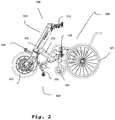
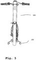
- FIGS. 1 and 2 show an embodiment of a wheelchair team 500 according to the invention, in which an embodiment of a pretensioning steering device 100 according to the invention is coupled ready for operation to a commercially available wheelchair 300.
- FIGS Figures 1 to 9 Details of the embodiment of the prestressing steering device 100 according to the invention, including an embodiment of a stand 200 according to the invention attached to it, are shown in particular in FIGS Figures 1 to 9 shown.
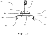
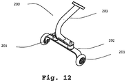
- FIGS Figures 10 to 12 An embodiment of the stand 200 according to the invention is taken on its own in FIGS Figures 10 to 12 shown.
- the preload steering device 100 has a main body 101, which can be designed in monocoque construction and has a steering column part 102 and a connecting part 103.
- a steering column (not shown) is rotatably mounted in the steering column part 102 of the main body 101 a handlebar 110 is attached to its upper end and a fork 104 is attached to its lower end.
- a main wheel 105 is guided in the fork 104 and can be driven by an electric motor 106 and braked by a disc brake 107. Operating elements for the control of the electric motor 106 and the actuation of the disc brake 107 are arranged on the handlebar 110.
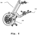
- the preload steering device 100 can be connected via a mounting arrangement 130 to a commercially available wheelchair 300 to form the wheelchair combination 500.
- the mounting arrangement 130 (see in particular Fig. 6 ) is arranged on the outer end of the connecting part 103 of the main body 101 of the prestressing steering device 100 and is designed such that it is adjustable and can be connected to a large number of commercially available wheelchairs 300.
- Fig. 2 As can be seen, in the ready-to-use state of the preload steering device 100 with the wheelchair 300, small front wheels 302 of the wheelchair, which are usually designed as freely pivoting castors, are lifted off the floor on which the wheelchair team 500 is standing, so that the wheelchair team 500 as a tricycle the main wheel 105 of the preload steering device 100 and the two large rear wheels 301 of the wheelchair 300.
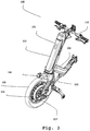
- the preload steering device 100 is provided with a stand 200.
- the stand 200 is attached to the connection part 103 of the main body 101 of the bias steering device 100. It is understood by a person skilled in the art that such a stand 200 can also be attached to other positions of a prestressing steering device.
- the stand 200 is provided with two roller wheels 201 which are arranged on a ground contact section 202 of the stand.
- the stand 200 makes it possible, when it is decoupled from the wheelchair 300, to hold the prestressing steering device 100 in an assembly position in which the prestressing steering device 100 stands on the main wheel 105 and the two roller wheels 201 of the stand 200.
- roller wheels 201 instead of Roller wheels 201 also other components can be used to bring the stand 200 into contact with the ground, which components can be both movable components and rigid components.
- the roller wheels 201 do not touch the ground on which the wheelchair team 500 is standing. They are thus lifted off the floor with respect to the mounting position of the preload steering device 100, just as the front wheels 302 of the wheelchair 300 are lifted off the floor with respect to a position in which the wheelchair, without being coupled to a preload steering device 100, on its front wheels 302 and its rear wheels 301 stands.
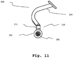
- the stand 200 is connected to the bias steering device 100 at its upper end of the mounting portion.
- the roller wheels 201 are attached to the lower end of the ground contact section 202.
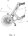
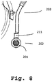
- a spring device 210 is arranged between the ground contact section 202 and the mounting section 203. The spring device 210 enables the ground contact section 202 to pivot elastically with the roller wheels 201 when it comes into contact with an obstacle. In particular, there is an elastic pivoting in the direction of travel, ie in a direction that in the illustration according to Fig. 2 runs from left to right and vice versa.
- the spring device 210 can also be arranged at other locations on the stand, including the upper end of the stand, ie the upper end of the mounting section 203 in the embodiment shown.
- a stator for example, which is otherwise rigid, could thus be connected to a corresponding connecting part of a preload steering device with the interposition of a spring device.
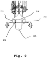
- the spring device 210 has two rubber-metal buffers 211 which are screwed to a first support plate 212 of the ground contact section 202 and a second support plate 213 of the mounting section 203 opposite the first support plate 212.
- These vibrating metal buffers have a circular cylindrical shape and have a spring stiffness in the direction of the cylinder axis which is considerably greater than the spring stiffness in the radial direction.
- two such rubber-metal buffers 211 are arranged spaced apart from one another in an arrangement direction which is perpendicular to the straight-ahead direction of travel of the wheelchair team and parallel to the floor.
- the spring device 210 thus has a spring stiffness in the straight travel direction that is less than in a direction that is perpendicular to the straight travel direction of the wheelchair team and parallel to the floor, the latter spring stiffness being even lower than that in a direction perpendicular to the floor.
Claims (9)
- Support (200) pour un dispositif de précontrainte de direction (100) pour un fauteuil roulant (300), lequel permet un maintien du dispositif de précontrainte de direction (100) dans une position de montage afin de monter le dispositif de précontrainte de direction (100) avec le fauteuil roulant (300) en un attelage de fauteuil roulant (500), dans lequel le support (200) comporte un moyen de ressort (210), lequel permet un pivotement élastique d'au moins une partie (202) du support (200) dans une direction d'avance droite de l'attelage de fauteuil roulant (500),
caractérisé en ce
que, par rapport aux trois axes d'un système de coordonnées cartésiennes, parmi lesquels le premier est la direction d'avance droite de l'attelage de fauteuil roulant (500), la raideur du moyen de ressort (210) dans la direction d'avance droite de l'attelage de fauteuil roulant (500) est plus faible que la raideur du moyen de ressort (210) sur au moins un des deux autres axes. - Support (200) selon la revendication 1, caractérisé en ce que la raideur du moyen de ressort (210) dans la direction d'avance droite de l'attelage de fauteuil roulant (500) est plus faible que la raideur du moyen de ressort (210) sur les deux autres axes.
- Support (200) selon l'une des revendications précédentes, caractérisé en ce que le support (200) comporte une section de montage (203), par le biais de laquelle il peut être fixé sur le dispositif de précontrainte de direction (100), et une section de contact avec le sol (202), laquelle sert à mettre en contact le support (200) avec le sol, et en ce que le moyen de ressort (210) est agencé entre la section de montage (203) et la section de contact avec le sol (202).
- Support (200) selon l'une des revendications précédentes, caractérisé en ce que le moyen de ressort (210) comporte au moins un élément de ressort (211).
- Support (200) selon la revendication 4, caractérisé en ce que le moyen de ressort (210) comporte deux éléments de ressort (211), dans lequel ceux-ci sont agencés à distance l'un de l'autre dans une direction d'agencement perpendiculaire à la direction d'avance droite de l'attelage de fauteuil roulant (500) et parallèle au sol.
- Support (200) selon la revendication 4 ou 5, caractérisé en ce que l'élément de ressort (210) comporte un bloc élastomère ou les éléments de ressort (211) comportent un bloc élastomère.
- Support (200) selon la revendication 6, caractérisé en ce que le bloc élastomère est un amortisseur caoutchouc-métal (211).
- Dispositif de précontrainte de direction (100) pour un fauteuil roulant (300) doté d'un support (200) selon l'une des revendications précédentes 1 à 7.
- Attelage de fauteuil roulant (500) doté d'un dispositif de précontrainte de direction (100) pour un fauteuil roulant (300) selon la revendication 8.
Applications Claiming Priority (1)
| Application Number | Priority Date | Filing Date | Title |
|---|---|---|---|
| DE102017130687.0A DE102017130687A1 (de) | 2017-12-20 | 2017-12-20 | Ständer, Vorspannlenkvorrichtung mit Ständer und Rollstuhlgespann mit Vorspannlenkvorrichtung |
Publications (2)
| Publication Number | Publication Date |
|---|---|
| EP3501469A1 EP3501469A1 (fr) | 2019-06-26 |
| EP3501469B1 true EP3501469B1 (fr) | 2020-03-04 |
Family
ID=63998543
Family Applications (1)
| Application Number | Title | Priority Date | Filing Date |
|---|---|---|---|
| EP18202490.1A Active EP3501469B1 (fr) | 2017-12-20 | 2018-10-25 | Support, dispositif de précontrainte de direction pourvu de support et attelage de fauteuil roulant pourvu de dispositif de précontrainte de direction |
Country Status (2)
| Country | Link |
|---|---|
| EP (1) | EP3501469B1 (fr) |
| DE (1) | DE102017130687A1 (fr) |
Families Citing this family (2)
| Publication number | Priority date | Publication date | Assignee | Title |
|---|---|---|---|---|
| KR20220042693A (ko) * | 2020-09-28 | 2022-04-05 | 현대자동차주식회사 | 퍼스널 모빌리티의 견인모듈 및 이를 포함하는 퍼스널 모빌리티, 퍼스널 모빌리티의 제어방법 |
| WO2023130287A1 (fr) * | 2022-01-06 | 2023-07-13 | 恩比尔(厦门)机械制造有限公司 | Jambe de support de tracteur électrique pour fauteuil roulant avec repose-pied |
Family Cites Families (9)
| Publication number | Priority date | Publication date | Assignee | Title |
|---|---|---|---|---|
| DE1614992U (de) * | 1950-01-02 | 1950-10-19 | Hans Wessel | Staender fuer fahrraeder o. dgl. |
| EP0629390A1 (fr) * | 1993-06-04 | 1994-12-21 | Hendrik Jan Ordelman | Cadre auxiliaire pour fauteuil roulant et fauteuil roulant utilisant ce cadre auxiliaire |
| DE19861127C2 (de) | 1998-03-21 | 2001-02-22 | Alber Ulrich Gmbh & Co Kg | Hilfsantriebsvorrichtung für Selbstfahrer-Rollstühle |
| DE20007793U1 (de) | 2000-05-03 | 2000-09-07 | Speedy Reha Technik Gmbh | Einrad-Rollstuhlgespann |
| DE10102855C1 (de) | 2001-01-23 | 2002-07-25 | Rolf Kuhlmann | Zugmittel für einen Rollstuhl |
| ES2425316B1 (es) | 2013-07-08 | 2014-08-05 | Batec Mobility, S.L. | Sistema auxiliar de movilidad para silla de ruedas |
| ES1089834Y (es) | 2013-07-08 | 2013-12-13 | Batec Mobility S L | Dispositivo de seguridad para un elemento auxiliar de silla de ruedas |
| US9056035B2 (en) * | 2013-09-12 | 2015-06-16 | Cycling & Health Tech Industry R&D Center | Manual tractor assembly for tracking wheel chair |
| KR101598484B1 (ko) * | 2014-06-23 | 2016-03-02 | 한국생산기술연구원 | 착탈 가능한 휠체어 주행보조장치 |
-
2017
- 2017-12-20 DE DE102017130687.0A patent/DE102017130687A1/de not_active Withdrawn
-
2018
- 2018-10-25 EP EP18202490.1A patent/EP3501469B1/fr active Active
Non-Patent Citations (1)
| Title |
|---|
| None * |
Also Published As
| Publication number | Publication date |
|---|---|
| DE102017130687A1 (de) | 2019-06-27 |
| EP3501469A1 (fr) | 2019-06-26 |
Similar Documents
| Publication | Publication Date | Title |
|---|---|---|
| DE602005004182T2 (de) | Anhänger mit heb- und senkbarer Manövrieranordnung | |
| DE2025795B2 (de) | Elektrisch angetriebenes Behindertenfahrzeug | |
| DE10136369C2 (de) | Kleinfahrzeug,insbesondere Rollstuhl | |
| DE102018128803A1 (de) | Antriebsvorrichtung eines rollstuhs zum elektrisch angetriebenen fahren | |
| CH698063B1 (de) | Lenkradeinheit und Rollstuhl mit mindestens einer Lenkradeinheit. | |
| DE10136368A1 (de) | Kleinfahrzeug, insbesondere Rollstuhl | |
| EP3501469B1 (fr) | Support, dispositif de précontrainte de direction pourvu de support et attelage de fauteuil roulant pourvu de dispositif de précontrainte de direction | |
| EP1786663B1 (fr) | Vehicule destine a des personnes handicapees | |
| DE102020208140A1 (de) | Kippstruktur für Mobilitätsvorrichtung und Mobilitätsvorrichtung mit dieser | |
| DE102013013324A1 (de) | Radaufhängung für ein Fahrzeug | |
| DE202018105819U1 (de) | Rollbrett | |
| DE10300513A1 (de) | Kutsche | |
| DE2724106A1 (de) | Bodenzugvorrichtung | |
| DE102008008731A1 (de) | Dreirädriges Fahrzeug mit Neigevorrichtung | |
| CH706683A2 (de) | Rollstuhl. | |
| DE3612891A1 (de) | Rollstuhl | |
| EP3507178B1 (fr) | Voiture porteur enfant | |
| DE102016118018B4 (de) | Chassis für eine Mobilitätshilfe und für einen Elektrorollstuhl | |
| DE102018130969A1 (de) | Antriebsanordnung für ein Fahrzeug und Fahrzeug mit der Antriebsanordnung | |
| DE202014102390U1 (de) | Höhenverstellung für Maschinenträger insbesondere Rasenmäher | |
| DE3127204C2 (fr) | ||
| EP1393703A1 (fr) | Chaise roulante à roues orientables | |
| DE1298013B (de) | Dreirad mit Tretkurbel- oder Kraftantrieb | |
| DE102016124424A1 (de) | Modulare Radanordnung für einen Rollstuhl | |
| DE3902003A1 (de) | Koppelvorrichtung fuer eine landmaschine |
Legal Events
| Date | Code | Title | Description |
|---|---|---|---|
| PUAI | Public reference made under article 153(3) epc to a published international application that has entered the european phase |
Free format text: ORIGINAL CODE: 0009012 |
|
| STAA | Information on the status of an ep patent application or granted ep patent |
Free format text: STATUS: THE APPLICATION HAS BEEN PUBLISHED |
|
| AK | Designated contracting states |
Kind code of ref document: A1 Designated state(s): AL AT BE BG CH CY CZ DE DK EE ES FI FR GB GR HR HU IE IS IT LI LT LU LV MC MK MT NL NO PL PT RO RS SE SI SK SM TR |
|
| AX | Request for extension of the european patent |
Extension state: BA ME |
|
| STAA | Information on the status of an ep patent application or granted ep patent |
Free format text: STATUS: REQUEST FOR EXAMINATION WAS MADE |
|
| 17P | Request for examination filed |
Effective date: 20190704 |
|
| RBV | Designated contracting states (corrected) |
Designated state(s): AL AT BE BG CH CY CZ DE DK EE ES FI FR GB GR HR HU IE IS IT LI LT LU LV MC MK MT NL NO PL PT RO RS SE SI SK SM TR |
|
| GRAP | Despatch of communication of intention to grant a patent |
Free format text: ORIGINAL CODE: EPIDOSNIGR1 |
|
| STAA | Information on the status of an ep patent application or granted ep patent |
Free format text: STATUS: GRANT OF PATENT IS INTENDED |
|
| RIC1 | Information provided on ipc code assigned before grant |
Ipc: A61G 5/04 20130101ALI20191107BHEP Ipc: A61G 5/02 20060101AFI20191107BHEP |
|
| INTG | Intention to grant announced |
Effective date: 20191205 |
|
| GRAS | Grant fee paid |
Free format text: ORIGINAL CODE: EPIDOSNIGR3 |
|
| GRAA | (expected) grant |
Free format text: ORIGINAL CODE: 0009210 |
|
| STAA | Information on the status of an ep patent application or granted ep patent |
Free format text: STATUS: THE PATENT HAS BEEN GRANTED |
|
| AK | Designated contracting states |
Kind code of ref document: B1 Designated state(s): AL AT BE BG CH CY CZ DE DK EE ES FI FR GB GR HR HU IE IS IT LI LT LU LV MC MK MT NL NO PL PT RO RS SE SI SK SM TR |
|
| REG | Reference to a national code |
Ref country code: GB Ref legal event code: FG4D Free format text: NOT ENGLISH |
|
| REG | Reference to a national code |
Ref country code: CH Ref legal event code: EP |
|
| REG | Reference to a national code |
Ref country code: AT Ref legal event code: REF Ref document number: 1239540 Country of ref document: AT Kind code of ref document: T Effective date: 20200315 |
|
| REG | Reference to a national code |
Ref country code: DE Ref legal event code: R096 Ref document number: 502018000889 Country of ref document: DE |
|
| REG | Reference to a national code |
Ref country code: IE Ref legal event code: FG4D Free format text: LANGUAGE OF EP DOCUMENT: GERMAN |
|
| PG25 | Lapsed in a contracting state [announced via postgrant information from national office to epo] |
Ref country code: NO Free format text: LAPSE BECAUSE OF FAILURE TO SUBMIT A TRANSLATION OF THE DESCRIPTION OR TO PAY THE FEE WITHIN THE PRESCRIBED TIME-LIMIT Effective date: 20200604 Ref country code: FI Free format text: LAPSE BECAUSE OF FAILURE TO SUBMIT A TRANSLATION OF THE DESCRIPTION OR TO PAY THE FEE WITHIN THE PRESCRIBED TIME-LIMIT Effective date: 20200304 Ref country code: RS Free format text: LAPSE BECAUSE OF FAILURE TO SUBMIT A TRANSLATION OF THE DESCRIPTION OR TO PAY THE FEE WITHIN THE PRESCRIBED TIME-LIMIT Effective date: 20200304 |
|
| REG | Reference to a national code |
Ref country code: NL Ref legal event code: MP Effective date: 20200304 |
|
| PG25 | Lapsed in a contracting state [announced via postgrant information from national office to epo] |
Ref country code: BG Free format text: LAPSE BECAUSE OF FAILURE TO SUBMIT A TRANSLATION OF THE DESCRIPTION OR TO PAY THE FEE WITHIN THE PRESCRIBED TIME-LIMIT Effective date: 20200604 Ref country code: HR Free format text: LAPSE BECAUSE OF FAILURE TO SUBMIT A TRANSLATION OF THE DESCRIPTION OR TO PAY THE FEE WITHIN THE PRESCRIBED TIME-LIMIT Effective date: 20200304 Ref country code: SE Free format text: LAPSE BECAUSE OF FAILURE TO SUBMIT A TRANSLATION OF THE DESCRIPTION OR TO PAY THE FEE WITHIN THE PRESCRIBED TIME-LIMIT Effective date: 20200304 Ref country code: GR Free format text: LAPSE BECAUSE OF FAILURE TO SUBMIT A TRANSLATION OF THE DESCRIPTION OR TO PAY THE FEE WITHIN THE PRESCRIBED TIME-LIMIT Effective date: 20200605 Ref country code: LV Free format text: LAPSE BECAUSE OF FAILURE TO SUBMIT A TRANSLATION OF THE DESCRIPTION OR TO PAY THE FEE WITHIN THE PRESCRIBED TIME-LIMIT Effective date: 20200304 |
|
| REG | Reference to a national code |
Ref country code: LT Ref legal event code: MG4D |
|
| PG25 | Lapsed in a contracting state [announced via postgrant information from national office to epo] |
Ref country code: NL Free format text: LAPSE BECAUSE OF FAILURE TO SUBMIT A TRANSLATION OF THE DESCRIPTION OR TO PAY THE FEE WITHIN THE PRESCRIBED TIME-LIMIT Effective date: 20200304 |
|
| PG25 | Lapsed in a contracting state [announced via postgrant information from national office to epo] |
Ref country code: ES Free format text: LAPSE BECAUSE OF FAILURE TO SUBMIT A TRANSLATION OF THE DESCRIPTION OR TO PAY THE FEE WITHIN THE PRESCRIBED TIME-LIMIT Effective date: 20200304 Ref country code: PT Free format text: LAPSE BECAUSE OF FAILURE TO SUBMIT A TRANSLATION OF THE DESCRIPTION OR TO PAY THE FEE WITHIN THE PRESCRIBED TIME-LIMIT Effective date: 20200729 Ref country code: IS Free format text: LAPSE BECAUSE OF FAILURE TO SUBMIT A TRANSLATION OF THE DESCRIPTION OR TO PAY THE FEE WITHIN THE PRESCRIBED TIME-LIMIT Effective date: 20200704 Ref country code: SK Free format text: LAPSE BECAUSE OF FAILURE TO SUBMIT A TRANSLATION OF THE DESCRIPTION OR TO PAY THE FEE WITHIN THE PRESCRIBED TIME-LIMIT Effective date: 20200304 Ref country code: SM Free format text: LAPSE BECAUSE OF FAILURE TO SUBMIT A TRANSLATION OF THE DESCRIPTION OR TO PAY THE FEE WITHIN THE PRESCRIBED TIME-LIMIT Effective date: 20200304 Ref country code: CZ Free format text: LAPSE BECAUSE OF FAILURE TO SUBMIT A TRANSLATION OF THE DESCRIPTION OR TO PAY THE FEE WITHIN THE PRESCRIBED TIME-LIMIT Effective date: 20200304 Ref country code: LT Free format text: LAPSE BECAUSE OF FAILURE TO SUBMIT A TRANSLATION OF THE DESCRIPTION OR TO PAY THE FEE WITHIN THE PRESCRIBED TIME-LIMIT Effective date: 20200304 Ref country code: EE Free format text: LAPSE BECAUSE OF FAILURE TO SUBMIT A TRANSLATION OF THE DESCRIPTION OR TO PAY THE FEE WITHIN THE PRESCRIBED TIME-LIMIT Effective date: 20200304 Ref country code: RO Free format text: LAPSE BECAUSE OF FAILURE TO SUBMIT A TRANSLATION OF THE DESCRIPTION OR TO PAY THE FEE WITHIN THE PRESCRIBED TIME-LIMIT Effective date: 20200304 |
|
| REG | Reference to a national code |
Ref country code: DE Ref legal event code: R097 Ref document number: 502018000889 Country of ref document: DE |
|
| PLBE | No opposition filed within time limit |
Free format text: ORIGINAL CODE: 0009261 |
|
| STAA | Information on the status of an ep patent application or granted ep patent |
Free format text: STATUS: NO OPPOSITION FILED WITHIN TIME LIMIT |
|
| PG25 | Lapsed in a contracting state [announced via postgrant information from national office to epo] |
Ref country code: IT Free format text: LAPSE BECAUSE OF FAILURE TO SUBMIT A TRANSLATION OF THE DESCRIPTION OR TO PAY THE FEE WITHIN THE PRESCRIBED TIME-LIMIT Effective date: 20200304 Ref country code: DK Free format text: LAPSE BECAUSE OF FAILURE TO SUBMIT A TRANSLATION OF THE DESCRIPTION OR TO PAY THE FEE WITHIN THE PRESCRIBED TIME-LIMIT Effective date: 20200304 |
|
| 26N | No opposition filed |
Effective date: 20201207 |
|
| PG25 | Lapsed in a contracting state [announced via postgrant information from national office to epo] |
Ref country code: PL Free format text: LAPSE BECAUSE OF FAILURE TO SUBMIT A TRANSLATION OF THE DESCRIPTION OR TO PAY THE FEE WITHIN THE PRESCRIBED TIME-LIMIT Effective date: 20200304 |
|
| PG25 | Lapsed in a contracting state [announced via postgrant information from national office to epo] |
Ref country code: MC Free format text: LAPSE BECAUSE OF FAILURE TO SUBMIT A TRANSLATION OF THE DESCRIPTION OR TO PAY THE FEE WITHIN THE PRESCRIBED TIME-LIMIT Effective date: 20200304 Ref country code: LU Free format text: LAPSE BECAUSE OF NON-PAYMENT OF DUE FEES Effective date: 20201025 |
|
| REG | Reference to a national code |
Ref country code: BE Ref legal event code: MM Effective date: 20201031 |
|
| PG25 | Lapsed in a contracting state [announced via postgrant information from national office to epo] |
Ref country code: BE Free format text: LAPSE BECAUSE OF NON-PAYMENT OF DUE FEES Effective date: 20201031 |
|
| PG25 | Lapsed in a contracting state [announced via postgrant information from national office to epo] |
Ref country code: IE Free format text: LAPSE BECAUSE OF NON-PAYMENT OF DUE FEES Effective date: 20201025 |
|
| REG | Reference to a national code |
Ref country code: CH Ref legal event code: PL |
|
| PG25 | Lapsed in a contracting state [announced via postgrant information from national office to epo] |
Ref country code: TR Free format text: LAPSE BECAUSE OF FAILURE TO SUBMIT A TRANSLATION OF THE DESCRIPTION OR TO PAY THE FEE WITHIN THE PRESCRIBED TIME-LIMIT Effective date: 20200304 Ref country code: MT Free format text: LAPSE BECAUSE OF FAILURE TO SUBMIT A TRANSLATION OF THE DESCRIPTION OR TO PAY THE FEE WITHIN THE PRESCRIBED TIME-LIMIT Effective date: 20200304 Ref country code: CY Free format text: LAPSE BECAUSE OF FAILURE TO SUBMIT A TRANSLATION OF THE DESCRIPTION OR TO PAY THE FEE WITHIN THE PRESCRIBED TIME-LIMIT Effective date: 20200304 |
|
| PG25 | Lapsed in a contracting state [announced via postgrant information from national office to epo] |
Ref country code: MK Free format text: LAPSE BECAUSE OF FAILURE TO SUBMIT A TRANSLATION OF THE DESCRIPTION OR TO PAY THE FEE WITHIN THE PRESCRIBED TIME-LIMIT Effective date: 20200304 Ref country code: AL Free format text: LAPSE BECAUSE OF FAILURE TO SUBMIT A TRANSLATION OF THE DESCRIPTION OR TO PAY THE FEE WITHIN THE PRESCRIBED TIME-LIMIT Effective date: 20200304 |
|
| PG25 | Lapsed in a contracting state [announced via postgrant information from national office to epo] |
Ref country code: LI Free format text: LAPSE BECAUSE OF NON-PAYMENT OF DUE FEES Effective date: 20211031 Ref country code: CH Free format text: LAPSE BECAUSE OF NON-PAYMENT OF DUE FEES Effective date: 20211031 |
|
| P01 | Opt-out of the competence of the unified patent court (upc) registered |
Effective date: 20230504 |
|
| GBPC | Gb: european patent ceased through non-payment of renewal fee |
Effective date: 20221025 |
|
| PG25 | Lapsed in a contracting state [announced via postgrant information from national office to epo] |
Ref country code: SI Free format text: LAPSE BECAUSE OF FAILURE TO SUBMIT A TRANSLATION OF THE DESCRIPTION OR TO PAY THE FEE WITHIN THE PRESCRIBED TIME-LIMIT Effective date: 20200304 |
|
| PG25 | Lapsed in a contracting state [announced via postgrant information from national office to epo] |
Ref country code: GB Free format text: LAPSE BECAUSE OF NON-PAYMENT OF DUE FEES Effective date: 20221025 |
|
| REG | Reference to a national code |
Ref country code: DE Ref legal event code: R082 Ref document number: 502018000889 Country of ref document: DE Representative=s name: RUEGER ABEL PATENTANWAELTE PARTGMBB, DE |
|
| PGFP | Annual fee paid to national office [announced via postgrant information from national office to epo] |
Ref country code: FR Payment date: 20231023 Year of fee payment: 6 Ref country code: DE Payment date: 20231017 Year of fee payment: 6 |