EP3501469B1 - Stand, leader guidance device with stand and wheelchair train with a leader guidance device - Google Patents
Stand, leader guidance device with stand and wheelchair train with a leader guidance device Download PDFInfo
- Publication number
- EP3501469B1 EP3501469B1 EP18202490.1A EP18202490A EP3501469B1 EP 3501469 B1 EP3501469 B1 EP 3501469B1 EP 18202490 A EP18202490 A EP 18202490A EP 3501469 B1 EP3501469 B1 EP 3501469B1
- Authority
- EP
- European Patent Office
- Prior art keywords
- steering device
- wheelchair
- stand
- support
- spring
- Prior art date
- Legal status (The legal status is an assumption and is not a legal conclusion. Google has not performed a legal analysis and makes no representation as to the accuracy of the status listed.)
- Active
Links
- 239000000872 buffer Substances 0.000 claims description 8
- 239000002184 metal Substances 0.000 claims description 8
- 229920001971 elastomer Polymers 0.000 claims description 5
- 239000000806 elastomer Substances 0.000 claims description 4
- 230000036316 preload Effects 0.000 description 38
- 235000004443 Ricinus communis Nutrition 0.000 description 3
- 240000000528 Ricinus communis Species 0.000 description 3
- 230000001419 dependent effect Effects 0.000 description 3
- 230000008878 coupling Effects 0.000 description 2
- 238000010168 coupling process Methods 0.000 description 2
- 238000005859 coupling reaction Methods 0.000 description 2
- 238000009434 installation Methods 0.000 description 2
- 229910001335 Galvanized steel Inorganic materials 0.000 description 1
- 238000010276 construction Methods 0.000 description 1
- 238000006073 displacement reaction Methods 0.000 description 1
- 239000008397 galvanized steel Substances 0.000 description 1
- 239000013589 supplement Substances 0.000 description 1
Images


Classifications
-
- A—HUMAN NECESSITIES
- A61—MEDICAL OR VETERINARY SCIENCE; HYGIENE
- A61G—TRANSPORT, PERSONAL CONVEYANCES, OR ACCOMMODATION SPECIALLY ADAPTED FOR PATIENTS OR DISABLED PERSONS; OPERATING TABLES OR CHAIRS; CHAIRS FOR DENTISTRY; FUNERAL DEVICES
- A61G5/00—Chairs or personal conveyances specially adapted for patients or disabled persons, e.g. wheelchairs
- A61G5/02—Chairs or personal conveyances specially adapted for patients or disabled persons, e.g. wheelchairs propelled by the patient or disabled person
- A61G5/027—Chairs or personal conveyances specially adapted for patients or disabled persons, e.g. wheelchairs propelled by the patient or disabled person by using auxiliary detachable mechanisms
-
- A—HUMAN NECESSITIES
- A61—MEDICAL OR VETERINARY SCIENCE; HYGIENE
- A61G—TRANSPORT, PERSONAL CONVEYANCES, OR ACCOMMODATION SPECIALLY ADAPTED FOR PATIENTS OR DISABLED PERSONS; OPERATING TABLES OR CHAIRS; CHAIRS FOR DENTISTRY; FUNERAL DEVICES
- A61G5/00—Chairs or personal conveyances specially adapted for patients or disabled persons, e.g. wheelchairs
- A61G5/04—Chairs or personal conveyances specially adapted for patients or disabled persons, e.g. wheelchairs motor-driven
- A61G5/047—Chairs or personal conveyances specially adapted for patients or disabled persons, e.g. wheelchairs motor-driven by a modular detachable drive system
Definitions
- the invention relates to a stand for a preload steering device, a preload steering device with stand and a wheelchair team with a preload steering device.
- Wheelchairs for people with disabilities usually have two large rear drive wheels (rear wheels) and two small, freely swiveling front wheels (front wheels), which are also known as castors.
- the rear wheels can generally be driven by hand using a hand ring.
- electrically driven rear wheels can also be used.
- Known rear wheels which are designed as an auxiliary drive device, have both an electric drive motor and a gripping ring for manual drive and in addition a sensor that detects a driving force manually introduced into the gripping ring, and a control device that the electric drive motor depending on size and Direction of the drive force manually introduced into the gripping ring and an adjustable degree of support for delivering a corresponding torque.
- the front wheels of the wheelchair which are designed as free-pivoting castors, ensure high maneuverability, especially when using the wheelchair indoors in closed rooms, is essential.
- the small front wheels are disadvantageous and make operation of the wheelchair impossible even with relatively small bumps.
- small front wheels would be immersed in recesses from which they would not be able to get out due to their small diameter ability to overcome an obstacle, which then makes it impossible to continue driving.
- pre-tensioning steering devices have been developed for wheelchairs in the form of removable additional devices, which make it possible to supplement and change the function of the wheelchair designed for indoor use in such a way that it is more suitable for outdoor use.
- a preload steering device for a wheelchair is for example from the EP 3 020 383 A1 known.
- Such a preload steering device is mounted on a wheelchair in such a way that the preload steering device is first placed in front of the wheelchair as viewed in the direction of travel and the freely pivotable front wheels of the wheelchair are lifted during assembly, so that the wheelchair combination assembled in this way is ready for use Vehicle that only touches the ground on which it is driving with the wheel or wheels of the preload steering device and the two large rear wheels of the wheelchair.
- a preload steering device with a stand that enables the preload steering device to be held in an assembly position, which is explained below, and / or in a standing and thus space-saving position (parking position) when the preload steering device is not used , ie not connected to a wheelchair.
- a bias steering device with a stand is from the EP 3 020 384 A1 known.
- the stand has two rigid, curved frame tubes, each with a small wheel at the lower ends is arranged.
- the assembly position relates to the assembly of the preload steering device on the wheelchair.
- these are automatic, i.e. can be carried out without outside help by a person who needs the wheelchair and is sitting in it.
- the preload steering device For mounting on the wheelchair, the preload steering device must be in an installation position that takes into account the dimensions of the wheelchair and the coupling mechanism between the wheelchair and the preload steering device.
- the operating position of the preload steering device i.e. the position that the preload steering device takes when it is connected to a wheelchair and the wheelchair ready for operation does not deviate too far from the installation position so that the amount of displacement and thus the force to be used during the coupling for the wheelchair user is as small as possible hold.
- Another technical approach is to provide an electrically operated lifting device to raise or lower the stand.
- Such a device is from the DE 200 07 793 U1 known. It has the disadvantage that it is technically complex, heavy and costly.
- the present invention has for its object to improve a stand for a preload steering device for a wheelchair in view of the above and to provide a preload steering device provided with such a stand and a wheelchair team provided with such a preload steering device.
- This object is achieved by a stand for a prestressing steering device with the features of claim 1, a prestressing steering device for a wheelchair with a stand according to claim 8 and a wheelchair combination with a prestressing steering device according to claim 9.
- Advantageous embodiments are the subject of the dependent claims.
- the stand according to the invention for a preload steering device for a wheelchair enables the preload steering device to be held in an assembly position for mounting the preload steering device with a wheelchair, so that the preload steering device is combined with the wheelchair to form a wheelchair team.
- the stand has a spring device which enables resilient pivoting of at least part of the stand in a straight-ahead direction of travel of the wheelchair team.
- the resilient pivoting of the stand makes it possible that when the pretensioning steering device is connected to the wheelchair to form a wheelchair team, that is to say in the ready-to-operate position of the pretensioning steering device, the stand can only have a relatively low ground clearance without the disadvantageous consequences explained in the beginning Purchase must be made.
- the positive consequence of this configuration is that the mounting position of the pretensioning steering device deviates only slightly from the operating position, which simplifies mounting, since only relatively small forces have to be applied due to the small change in position. The disadvantage inherently caused by this is remedied by the resilient pivoting.
- the stand is designed so that, based on the three spatial axes of a Cartesian coordinate system, a first of which is the straight-ahead direction of the wheelchair team, the spring stiffness of the spring device in the straight-ahead direction of the wheelchair team is less than the spring stiffness of the spring device in at least one, preferably both of the two other spatial axes.
- This configuration enables a slight resilient pivoting of the stand or a part of the stand in a straight-ahead direction of travel of the wheelchair team, while, on the other hand, due to the higher spring stiffness in one or two other spatial axes, a stable position of the preload steering device is ensured in the assembly position.
- the stand can have a mounting section, by means of which it can be fastened to the prestressing steering device, and a floor contact section, which serves for the contact of the stand with the floor.
- the spring device can be arranged between the mounting section and the ground contact section. It is also possible that wheels are provided on the ground contact section, which enable the preload steering device to be moved easily in the installed position.
- the spring device can have at least one spring element.
- the spring device has two spring elements. These are preferably arranged at a distance from one another in an arrangement direction, the arrangement direction being perpendicular to the straight travel direction of the wheelchair team and parallel to the floor.
- the spring element or the spring elements can have an elastomer block, for example a rubber-metal buffer.
- the bias steering device according to the invention with a stand can be provided with a drive motor that drives a main or drive wheel of the bias steering device.
- This not only represents a pre-tension steering device, but is also a traction device for the wheelchair.
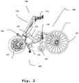
- FIGS. 1 and 2 show an embodiment of a wheelchair team 500 according to the invention, in which an embodiment of a pretensioning steering device 100 according to the invention is coupled ready for operation to a commercially available wheelchair 300.
- FIGS Figures 1 to 9 Details of the embodiment of the prestressing steering device 100 according to the invention, including an embodiment of a stand 200 according to the invention attached to it, are shown in particular in FIGS Figures 1 to 9 shown.
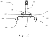
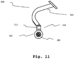
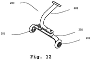
- FIGS Figures 10 to 12 An embodiment of the stand 200 according to the invention is taken on its own in FIGS Figures 10 to 12 shown.
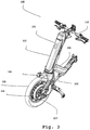
- the preload steering device 100 has a main body 101, which can be designed in monocoque construction and has a steering column part 102 and a connecting part 103.
- a steering column (not shown) is rotatably mounted in the steering column part 102 of the main body 101 a handlebar 110 is attached to its upper end and a fork 104 is attached to its lower end.
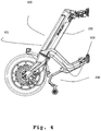
- a main wheel 105 is guided in the fork 104 and can be driven by an electric motor 106 and braked by a disc brake 107. Operating elements for the control of the electric motor 106 and the actuation of the disc brake 107 are arranged on the handlebar 110.
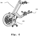
- the preload steering device 100 can be connected via a mounting arrangement 130 to a commercially available wheelchair 300 to form the wheelchair combination 500.
- the mounting arrangement 130 (see in particular Fig. 6 ) is arranged on the outer end of the connecting part 103 of the main body 101 of the prestressing steering device 100 and is designed such that it is adjustable and can be connected to a large number of commercially available wheelchairs 300.
- Fig. 2 As can be seen, in the ready-to-use state of the preload steering device 100 with the wheelchair 300, small front wheels 302 of the wheelchair, which are usually designed as freely pivoting castors, are lifted off the floor on which the wheelchair team 500 is standing, so that the wheelchair team 500 as a tricycle the main wheel 105 of the preload steering device 100 and the two large rear wheels 301 of the wheelchair 300.
- the preload steering device 100 is provided with a stand 200.
- the stand 200 is attached to the connection part 103 of the main body 101 of the bias steering device 100. It is understood by a person skilled in the art that such a stand 200 can also be attached to other positions of a prestressing steering device.
- the stand 200 is provided with two roller wheels 201 which are arranged on a ground contact section 202 of the stand.
- the stand 200 makes it possible, when it is decoupled from the wheelchair 300, to hold the prestressing steering device 100 in an assembly position in which the prestressing steering device 100 stands on the main wheel 105 and the two roller wheels 201 of the stand 200.
- roller wheels 201 instead of Roller wheels 201 also other components can be used to bring the stand 200 into contact with the ground, which components can be both movable components and rigid components.
- the roller wheels 201 do not touch the ground on which the wheelchair team 500 is standing. They are thus lifted off the floor with respect to the mounting position of the preload steering device 100, just as the front wheels 302 of the wheelchair 300 are lifted off the floor with respect to a position in which the wheelchair, without being coupled to a preload steering device 100, on its front wheels 302 and its rear wheels 301 stands.
- the stand 200 is connected to the bias steering device 100 at its upper end of the mounting portion.
- the roller wheels 201 are attached to the lower end of the ground contact section 202.
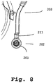
- a spring device 210 is arranged between the ground contact section 202 and the mounting section 203. The spring device 210 enables the ground contact section 202 to pivot elastically with the roller wheels 201 when it comes into contact with an obstacle. In particular, there is an elastic pivoting in the direction of travel, ie in a direction that in the illustration according to Fig. 2 runs from left to right and vice versa.
- the spring device 210 can also be arranged at other locations on the stand, including the upper end of the stand, ie the upper end of the mounting section 203 in the embodiment shown.
- a stator for example, which is otherwise rigid, could thus be connected to a corresponding connecting part of a preload steering device with the interposition of a spring device.
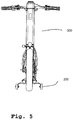
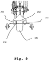
- the spring device 210 has two rubber-metal buffers 211 which are screwed to a first support plate 212 of the ground contact section 202 and a second support plate 213 of the mounting section 203 opposite the first support plate 212.
- These vibrating metal buffers have a circular cylindrical shape and have a spring stiffness in the direction of the cylinder axis which is considerably greater than the spring stiffness in the radial direction.
- two such rubber-metal buffers 211 are arranged spaced apart from one another in an arrangement direction which is perpendicular to the straight-ahead direction of travel of the wheelchair team and parallel to the floor.
- the spring device 210 thus has a spring stiffness in the straight travel direction that is less than in a direction that is perpendicular to the straight travel direction of the wheelchair team and parallel to the floor, the latter spring stiffness being even lower than that in a direction perpendicular to the floor.
Description
Die Erfindung betrifft einen Ständer für eine Vorspannlenkvorichtung, eine Vorspannlenkvorrichtung mit Ständer und ein Rollstuhlgespann mit einer Vorspannlenkvorrichtung.The invention relates to a stand for a preload steering device, a preload steering device with stand and a wheelchair team with a preload steering device.
Rollstühle für Menschen mit Behinderung verfügen üblicherweise über zwei große, in Vorwärtsfahrtrichtung gesehen hinten angeordnete Antriebsräder (Hinterräder) und zwei kleine, frei schwenkbare und in Vorwärtsfahrtrichtung vorne angeordnete Laufräder (Vorderräder), die auch Castoren genannt werden. Die Hinterräder sind bei manuell antreibbaren Rollstühlen in der Regel von Hand über einen Greifring antreibbar. Alternativ können auch elektrisch angetriebene Hinterräder verwendet werden. Zudem sind, beispielsweise aus der
Die als frei schwenkbare Castoren ausgeführten Vorderräder des Rollstuhls gewährleisten eine hohe Manövrierfähigkeit, die insbesondere bei sogenanntem Indoor-Betrieb, das heißt bei einer Verwendung des Rollstuhls in geschlossenen Räumen, unabdingbar ist. Bei Outdoor-Betrieb, das heißt bei Betrieb außerhalb geschlossener Räume und insbesondere auf unebenen Wegen, sind die kleinen Vorderräder hingegen nachteilig und machen schon bei relativ geringen Unebenheiten einen Betrieb des Rollstuhls unmöglich. Beispielsweise würden kleine Vorderräder in Vertiefungen eintauchen, aus denen sie wegen ihrer durch den kleinen Durchmesser deutlich eingeschränkten Fähigkeit zum Überwinden eines Hindernisses nicht herauskommen könnten, was dann ein Weiterfahren unmöglich macht.The front wheels of the wheelchair, which are designed as free-pivoting castors, ensure high maneuverability, especially when using the wheelchair indoors in closed rooms, is essential. In the case of outdoor operation, i.e. when operating outside closed rooms and especially on uneven paths, the small front wheels are disadvantageous and make operation of the wheelchair impossible even with relatively small bumps. For example, small front wheels would be immersed in recesses from which they would not be able to get out due to their small diameter ability to overcome an obstacle, which then makes it impossible to continue driving.
Es sind daher für Rollstühle sogenannte Vorspannlenkvorrichtungen entwickelt worden in Form abnehmbarer Zusatzeinrichtungen, die es ermöglichen, den für den Indoor-Betrieb ausgelegten Rollstuhl funktional so zu ergänzen und zu verändern, dass er für den Outdoor-Betrieb besser geeignet ist. Eine derartige Vorspannlenkvorrichtung für einen Rollstuhl ist beispielsweise aus der
Es ist zudem bekannt, eine derartige Vorspannlenkvorrichtung mit einem Ständer zu versehen, der ein Halten der Vorspannlenkvorrichtung ermöglicht in einer Montagestellung, die nachfolgend erläutert wird, und/oder in einer stehenden und damit platzsparenden Lage (Abstellstellung) dann, wenn die Vorspannlenkvorrichtung nicht gebraucht wird, d.h. nicht mit einem Rollstuhl verbunden ist. Eine derartige Vorspannlenkvorrichtung mit einem Ständer ist aus der
Die Montagestellung betrifft die Montage der Vorspannlenkvorrichtung an dem Rollstuhl. Diesbezüglich ist es erstrebenswert, dass diese selbsttätig, d.h. ohne fremde Hilfe, von einer den Rollstuhl benötigenden und in diesem sitzenden Person durchgeführt werden kann. Zu der Montage an dem Rollstuhl muss sich die Vorspannlenkvorrichtung in einer Montagestellung befinden, die den Abmessungen des Rollstuhls und des Koppelungsmechanismus zwischen Rollstuhl und Vorspannlenkvorrichtung Rechnung trägt.The assembly position relates to the assembly of the preload steering device on the wheelchair. In this regard, it is desirable that these are automatic, i.e. can be carried out without outside help by a person who needs the wheelchair and is sitting in it. For mounting on the wheelchair, the preload steering device must be in an installation position that takes into account the dimensions of the wheelchair and the coupling mechanism between the wheelchair and the preload steering device.
Um die Montage der Vorspannlenkvorrichtung an dem Rollstuhl zu erleichtern ist es zweckdienlich, dass die Betriebsstellung der Vorspannlenkvorrichtung, d.h. die Stellung, die die Vorspannlenkvorrichtung einnimmt, wenn sie betriebsfertig mit dem Rollstuhl zu einem Rollstuhlgespann verbunden ist, nicht zu weit von der Montagestellung abweicht, um so den Verschiebungsbetrag und damit die aufzuwendende Kraft während der Ankoppelung für den Rollstuhlfahrer bzw. die Rollstuhlfahrerin möglichst gering zu halten.In order to facilitate the assembly of the preload steering device on the wheelchair, it is expedient that the operating position of the preload steering device, i.e. the position that the preload steering device takes when it is connected to a wheelchair and the wheelchair ready for operation does not deviate too far from the installation position so that the amount of displacement and thus the force to be used during the coupling for the wheelchair user is as small as possible hold.
Eine solche geringe Abweichung zwischen Montagestellung und Betriebsstellung der Vorspannlenkvorrichtung führt dazu, dass bei bekannten Vorspannlenkvorrichtungen der Ständer in der Betriebsstellung so angeordnet ist, dass er eine nur geringe Bodenfreiheit aufweist. Dies hat zur Folge, dass Teile des Ständers beim Überwinden von Hindernissen wie beispielsweise Bordsteinen leicht mit diesen kollidieren. Da der Ständer zudem eine ausreichende Starrheit aufweisen muss, um die Vorspannlenkvorrichtung in der Abstell- und Montagestellung sicher zu halten, führt dies dazu, dass er bei derartigen Kollisionen beim Überwinden von Hindernissen entweder beschädigt wird oder ein Überwinden dieses Hindernisses verhindert.Such a slight deviation between the assembly position and the operating position of the pretensioning steering device leads to the fact that, in known pretensioning steering devices, the stand is arranged in the operating position such that it has only little ground clearance. As a result, parts of the stand collide easily with obstacles such as curbs. In addition, since the stand must have sufficient rigidity to hold the pretensioning steering device securely in the parking and assembly position, this means that in the event of such collisions, when overcoming obstacles, it is either damaged or prevents this obstacle from being overcome.
Aus der
Ein anderer technischer Ansatz besteht darin, eine elektrisch betriebene Hubvorrichtung vorzusehen, um den Ständer anzuheben bzw. abzusenken. Eine derartige Vorrichtung ist aus der
Weitere Vorspannlenkvorrichtungen sind in
Der vorliegenden Erfindung liegt die Aufgabe zugrunde, einen Ständer für eine Vorspannlenkvorrichtung für einen Rollstuhl im Hinblick auf das vorstehend Dargelegte zu verbessern und eine mit einem derartigen Ständer versehene Vorspannlenkvorrichtung und ein mit einer derartigen Vorspannlenkvorrichtung versehenes Rollstuhlgespann bereitzustellen. Gelöst wird diese Aufgabe durch einen Ständer für eine Vorspannlenkvorrichtung mit den Merkmalen des Patentanspruchs 1, eine Vorspannlenkvorrichtung für einen Rollstuhl mit einem Ständer gemäß Patentanspruch 8 und ein Rollstuhlgespann mit einer Vorspannlenkvorrichtung gemäß Patentanspruch 9. Vorteilhafte Ausgestaltungen sind jeweils Gegenstand der abhängigen Patentansprüche.The present invention has for its object to improve a stand for a preload steering device for a wheelchair in view of the above and to provide a preload steering device provided with such a stand and a wheelchair team provided with such a preload steering device. This object is achieved by a stand for a prestressing steering device with the features of claim 1, a prestressing steering device for a wheelchair with a stand according to claim 8 and a wheelchair combination with a prestressing steering device according to claim 9. Advantageous embodiments are the subject of the dependent claims.
Der erfindungsgemäße Ständer für eine Vorspannlenkvorrichtung für einen Rollstuhl ermöglicht ein Halten der Vorspannlenkvorrichtung in einer Montagestellung zur Montage der Vorspannlenkvorrichtung mit einem Rollstuhl, so dass die Vorspannlenkvorrichtung mit dem Rollstuhl zu einem Rollstuhlgespann zusammengeschlossen werden. Der Ständer weist eine Federeinrichtung auf, die ein federndes Verschwenken von zumindest einem Teil des Ständers in einer Geradeausfahrrichtung des Rollstuhlgespanns ermöglicht.The stand according to the invention for a preload steering device for a wheelchair enables the preload steering device to be held in an assembly position for mounting the preload steering device with a wheelchair, so that the preload steering device is combined with the wheelchair to form a wheelchair team. The stand has a spring device which enables resilient pivoting of at least part of the stand in a straight-ahead direction of travel of the wheelchair team.
Das federnde Verschwenken des Ständers ermöglicht es, dass dann, wenn die Vorspannlenkvorrichtung mit dem Rollstuhl zu einem Rollstuhlgespann verbunden ist, das heißt in der betriebsfertigen Stellung der Vorspannlenkvorrichtung, der Ständer nur eine relative geringe Bodenfreiheit aufweisen kann, ohne dass die eingangs erläuterten nachteiligen Folgen in Kauf genommen werden müssen. Positive Folge dieser Ausgestaltung ist es, dass die Montagestellung der Vorspannlenkvorrichtung nur relativ geringfügig von der Betriebsstellung abweicht, was die Montage vereinfacht, da aufgrund der nur geringen Lageveränderung nur relativ geringe Kräfte aufzubringen sind. Dem prinzipiell hierdurch bedingten Nachteil wird durch das federnde Verschwenken abgeholfen.The resilient pivoting of the stand makes it possible that when the pretensioning steering device is connected to the wheelchair to form a wheelchair team, that is to say in the ready-to-operate position of the pretensioning steering device, the stand can only have a relatively low ground clearance without the disadvantageous consequences explained in the beginning Purchase must be made. The positive consequence of this configuration is that the mounting position of the pretensioning steering device deviates only slightly from the operating position, which simplifies mounting, since only relatively small forces have to be applied due to the small change in position. The disadvantage inherently caused by this is remedied by the resilient pivoting.
Der Ständer ist so ausgeführt, dass, bezogen auf die drei Raumachsen eines kartesischen Koordinatensystems, von denen eine erste die Geradeausfahrrichtung des Rollstuhlgespanns ist, die Federsteifigkeit der Federeinrichtung in der Geradeausfahrrichtung des Rollstuhlgespanns geringer ist als die Federsteifigkeit der Federeinrichtung in mindestens einer, vorzugsweise beiden der beiden anderen Raumachsen.The stand is designed so that, based on the three spatial axes of a Cartesian coordinate system, a first of which is the straight-ahead direction of the wheelchair team, the spring stiffness of the spring device in the straight-ahead direction of the wheelchair team is less than the spring stiffness of the spring device in at least one, preferably both of the two other spatial axes.
Durch diese Ausgestaltung wird ein leichtes federndes Verschwenken des Ständers bzw. eines Teils des Ständers in einer Geradeausfahrrichtung des Rollstuhlgespanns ermöglicht, während andererseits, aufgrund der höheren Federsteifigkeiten in einer der oder beiden anderen Raumachsen, ein stabiler Stand der Vorspannlenkvorrichtung in der Montagestellung gewährleistet ist.This configuration enables a slight resilient pivoting of the stand or a part of the stand in a straight-ahead direction of travel of the wheelchair team, while, on the other hand, due to the higher spring stiffness in one or two other spatial axes, a stable position of the preload steering device is ensured in the assembly position.
Der Ständer kann einen Montageabschnitt aufweisen, über den er an der Vorspannlenkvorrichtung befestigbar ist, sowie einen Bodenberührabschnitt, der dem Kontakt des Ständers mit dem Boden dient. Die Federeinrichtung kann zwischen dem Montageabschnitt und dem Bodenberührabschnitt angeordnet sein. Es ist zudem möglich, dass an dem Bodenberührabschnitt Räder vorgesehen sind, die ein leichtes Verfahren der Vorspannlenkvorrichtung in der Montagestellung ermöglichen.The stand can have a mounting section, by means of which it can be fastened to the prestressing steering device, and a floor contact section, which serves for the contact of the stand with the floor. The spring device can be arranged between the mounting section and the ground contact section. It is also possible that wheels are provided on the ground contact section, which enable the preload steering device to be moved easily in the installed position.
Die Federeinrichtung kann mindestens ein Federelement aufweisen. In einer vorteilhaften Ausführungsform weist die Federeinrichtung zwei Federelemente auf. Diese sind vorzugsweise in einer Anordnungsrichtung beabstandet zueinander angeordnet, wobei die Anordnungsrichtung senkrecht zur Geradeausfahrrichtung des Rollstuhlgespanns und parallel zum Boden verläuft.The spring device can have at least one spring element. In an advantageous embodiment, the spring device has two spring elements. These are preferably arranged at a distance from one another in an arrangement direction, the arrangement direction being perpendicular to the straight travel direction of the wheelchair team and parallel to the floor.
Das Federelement bzw. die Federelemente können einen Elastomerblock aufweisen, beispielsweise einen Gummi-Metall-Puffer.The spring element or the spring elements can have an elastomer block, for example a rubber-metal buffer.
Die erfindungsgemäße Vorspannlenkvorrichtung mit einem Ständer, wie er in der vorliegenden Anmeldung offenbart ist, kann mit einem Antriebsmotor versehen sein, der ein Haupt- bzw. Antriebsrad der Vorspannlenkvorrichtung antreibt. Diese stellt dann nicht nur eine Vorspannlenkvorrichtung dar, sondern ist gleichzeitig ein Zugmittel für den Rollstuhl.The bias steering device according to the invention with a stand, as disclosed in the present application, can be provided with a drive motor that drives a main or drive wheel of the bias steering device. This not only represents a pre-tension steering device, but is also a traction device for the wheelchair.
Die Erfindung sowie das technische Umfeld werden nachfolgend anhand der Figuren näher erläutert. Es ist darauf hinzuweisen, dass die Figuren besonders bevorzugte Ausführungsvarianten der Erfindung zeigen. Die Erfindung ist jedoch nicht auf die gezeigten Ausführungsvarianten beschränkt.The invention and the technical environment are explained in more detail below with reference to the figures. It should be pointed out that the figures show particularly preferred embodiment variants of the invention. However, the invention is not limited to the embodiment variants shown.
Es zeigen:
-
Fig. 1 eine perspektivische Ansicht eines Rollstuhlgespanns, -
Fig. 2 eine Seitenansicht des Rollstuhlgespanns gemäßFig. 1 , -
Fig. 3 eine erste perspektivische Ansicht einer Vorspannlenkvorrichtung, -
Fig. 4 eine Seitenansicht der Vorspannlenkvorrichtung gemäßFig. 3 , -
Fig. 5 eine Frontansicht der Vorspannlenkvorrichtung gemäßFig. 3 , -
Fig. 6 eine zweite perspektivische Ansicht der Vorspannlenkvorrichtung gemäßFig. 3 , -
Fig. 7 eine vergrößerte Teilansicht eines an einer Vorspannlenkvorrichtung montierten Ständers, -
Fig. 8 eine Seitenansicht des Ständers gemäßFig. 7 , -
Fig. 9 eine Rückansicht des Ständers gemäßFig. 7 , -
Fig. 10 eine Einzeldarstellung eines Ständers von hinten, -
Fig. 11 eine Darstellung des Ständers gemäßFig. 10 von der Seite und -
Fig. 12 eine perspektivische Darstellung des Ständers gemäßFig. 10 .
-
Fig. 1 a perspective view of a wheelchair team, -
Fig. 2 a side view of the wheelchair team in accordanceFig. 1 . -
Fig. 3 1 shows a first perspective view of a prestressing steering device, -
Fig. 4 a side view of the bias steering device according toFig. 3 . -
Fig. 5 a front view of the bias steering device according toFig. 3 . -
Fig. 6 a second perspective view of the bias steering device according toFig. 3 . -
Fig. 7 2 shows an enlarged partial view of a stand mounted on a prestressing steering device, -
Fig. 8 a side view of the stand according toFig. 7 . -
Fig. 9 a rear view of the stand according toFig. 7 . -
Fig. 10 a single view of a stand from behind, -
Fig. 11 a representation of the stand accordingFig. 10 from the side and -
Fig. 12 a perspective view of the stand according toFig. 10 ,
Die
Einzelheiten der Ausführungsform der erfindungsgemäßen Vorspannlenkvorrichtung 100 einschließlich einer daran angebrachten Ausführungsform eines erfindungsgemäßen Ständers 200 sind insbesondere in den
Eine Ausführungsform des erfindungsgemäßen Ständers 200 ist für sich genommen in den
Die Vorspannlenkvorrichtung 100 weist einen Hauptkörper 101 auf, der in Monocoquebauweise ausgeführt sein kann und ein Lenksäulenteil 102 sowie ein Verbindungsteil 103 aufweist. In dem Lenksäulenteil 102 des Hauptkörpers 101 ist eine Lenksäule (nicht gezeigt) drehbar gelagert, an deren oberen Ende ein Lenker 110 und an deren unteren Ende eine Gabel 104 befestigt ist. In der Gabel 104 ist ein Hauptrad 105 geführt, das durch einen Elektromotor 106 angetrieben und über eine Scheibenbremse 107 gebremst werden kann. Bedienungselemente für die Ansteuerung des Elektromotors 106 und die Betätigung der Scheibenbremse 107 sind an dem Lenker 110 angeordnet.The
Die Vorspannlenkvorrichtung 100 kann über eine Montageanordnung 130 mit einem handelsüblichen Rollstuhl 300 verbunden werden zu dem Rollstuhlgespann 500. Die Montageanordnung 130 (siehe insbesondere
Wie insbesondere aus
Die Vorspannlenkvorrichtung 100 ist mit einem Ständer 200 versehen. In der dargestellten Ausführungsform ist der Ständer 200 an dem Verbindungsteil 103 des Hauptkörpers 101 der Vorspannlenkvorrichtung 100 befestigt. Es versteht sich für den Fachmann, dass ein derartiger Ständer 200 auch an anderen Positionen einer Vorspannlenkvorrichtung befestigt werden kann.The
Der Ständer 200 ist mit zwei Rollrädern 201 versehen, die an einem Bodenberührabschnitt 202 des Ständers angeordnet sind. Der Ständer 200 ermöglicht es, die Vorspannlenkvorrichtung 100 dann, wenn sie von dem Rollstuhl 300 entkoppelt ist, in einer Montagestellung zu halten, in der die Vorspannlenkvorrichtung 100 auf dem Hauptrad 105 und den beiden Rollrädern 201 des Ständers 200 steht. Es versteht sich, dass statt der Rollräder 201 auch andere Bauteile verwendet werden können, um den Ständer 200 mit dem Boden in Berührung zu bringen, wobei diese Bauteile sowohl bewegliche Bauteile als auch starre Bauteile sein können.The
In der Betriebsstellung der Vorspannlenkvorrichtung 100, d. h. in der Stellung, in der die Vorspannlenkvorrichtung 100 mit dem Rollstuhl 300 zu einem Rollstuhlgespann 500 verbunden ist, wie sie in
Der Ständer 200 ist mit seinem oberen Ende des Montageabschnitts mit der Vorspannlenkvorrichtung 100 verbunden. Wie bereits ausgeführt, sind die Rollräder 201 am unteren Ende des Bodenberührabschnitts 202 befestigt. Zwischen dem Bodenberührabschnitt 202 und dem Montageabschnitt 203 ist eine Federeinrichtung 210 angeordnet. Die Federeinrichtung 210 ermöglicht es, dass der Bodenberührabschnitt 202 mit den Rollrädern 201 elastisch verschwenken kann, wenn er mit einem Hindernis in Berührung kommt. Insbesondere ist ein elastisches Verschwenken in Fahrtrichtung, d. h. in einer Richtung, die bei der Darstellung gemäß
Es versteht sich, dass die Federeinrichtung 210 auch an anderen Stellen des Ständers angeordnet sein kann, einschließlich dem oberen Ende des Ständers, d. h. bei der dargestellten Ausführungsform dem oberen Ende des Montageabschnitts 203. Bei einer derartigen Ausführungsform, die in den Figuren nicht gezeigt ist, könnte somit ein beispielsweise im Übrigen starrer Ständer unter Zwischenschaltung einer Federeinrichtung mit einem entsprechenden Verbindungsteil einer Vorspannlenkvorrichtung verbunden sein.It goes without saying that the
Die Federeinrichtung 210 weist zwei Gummi-Metall-Puffer 211 auf, die mit einer ersten Trägerplatte 212 des Bodenberührabschnitts 202 und einer der ersten Trägerplatte 212 gegenüberliegenden zweiten Trägerplatte 213 des Montageabschnitts 203 verschraubt sind. Gut geeignet als derartige Gummi-Metall-Puffer 211 sind beispielsweise Schwingmetallpuffer der Firma Reiff Technische Produkte GmbH, Reutlingen, Deutschland, bei denen ein Elastomer zwischen zwei Platten aus verzinktem Stahl angeordnet sind. Diese Schwingmetallpuffer weisen eine kreiszylindrische Form auf und haben eine Federsteifigkeit in Richtung der Zylinderachse, die erheblich größer ist als die Federsteifigkeit in radialer Richtung. Bei der in den Figuren gezeigten Ausführungsformen des Ständers 200 sind zwei derartige Gummi-Metall-Puffer 211 zueinander beabstandet in einer Anordnungsrichtung angeordnet, die senkrecht zur Geradeausfahrrichtung des Rollstuhlgespanns und parallel zum Boden verläuft. Die Federeinrichtung 210 weist somit eine Federsteifigkeit in Geradeausfahrrichtung auf, die geringer ist als in einer Richtung, welche senkrecht zur Geradeausfahrrichtung des Rollstuhlgespanns und parallel zum Boden verläuft, wobei die letztgenannte Federsteifigkeit nochmals geringer ist als diejenige in einer Richtung senkrecht zum Boden.The
- 100100
- VorspannlenkvorrichtungPreload steering device
- 101101
- HauptkörperMain body
- 102102
- LenksäulenteilSteering column part
- 103103
- Verbindungsteilconnecting part
- 104104
- Gabelfork
- 105105
- HauptradMain wheel
- 106106
- ElektromotorElectric motor
- 107107
- Scheibenbremsedisc brake
- 110110
- LenkerHandlebars
- 130130
- MontageanordnungAssembly arrangement
- 200200
- StänderStand
- 201201
- RollräderRoller bikes
- 202202
- BodenberührabschnittGround contact section
- 203203
- MontageabschnittAssembly section
- 210210
- FedereinrichtungSpring device
- 211211
- Gummi-Metall-PufferRubber metal buffer
- 212212
- erste Trägerplattefirst carrier plate
- 213213
- zweite Trägerplattesecond carrier plate
- 300300
- Rollstuhlwheelchair
- 301301
- HinterräderRear wheels
- 302302
- VorderräderFront wheels
- 500500
- RollstuhlgespannTeam of wheelchairs
Claims (9)
- Support (200) for a leading steering device (100) for a wheel chair (300) enabling to hold the leading steering device (100) in an assembly position for assembling the leading steering device (100) with the wheel chair (300) to form a wheel chair combination (500) , wherein the support (200) comprises a spring means (210) enabling to resiliently pivot at least a part (202) of the support (200) in a straight travelling direction of the wheel chair combination (500),
characterized in that,
related to the three space axes of a Cartesian coordinate system, of which a first one is the straight travelling direction of the wheel chair combination (500), the spring rigidity of the spring means (210) is, in the straight travelling direction of the wheel chair combination (500), lower than the spring rigidity of the spring means (210) in at least one of the two other space axes. - Support (200) according to claim 1, characterized in that the spring rigidity of the spring means (210) in the straight travelling direction of the wheel chair combination (500) is lower than the spring rigidity of the spring means (210) in the two other space axes.
- Support (200) according to one of the preceding claims, characterized in that the support (200) comprises an assembly portion (203) via which it can be fixed to the leading steering device (100), and a floor contact section (202) which serves the contact between the support (200) and the floor, and that the spring means (210) is disposed between the assembly portion (203) and the floor contact portion (202).
- Support (200) according to one of the preceding claims, characterized in that the spring means (210) comprises at least one spring element (211).
- Support (200) according to claim 4, characterized in that the spring means (210) comprises two spring elements (211), the latter being disposed in an arrangement direction extending perpendicular to the straight travelling direction of the wheel chair combination (500) and parallel to the floor, and spaced apart with respect to each other.
- Support (200) according to claim 4 or 5, characterized in that the spring element (211) or the spring elements (211) comprise(s) an elastomer block.
- Support according to claim 6, characterized in that the elastomer block is a rubber-metal buffer (211).
- Leading steering device (100) for a wheel chair (300) with a support (200) according to one of the preceding claims 1 to 7.
- Wheel chair combination (500) with a leading steering device (100) for a wheel chair (300) according to claim 8.
Applications Claiming Priority (1)
| Application Number | Priority Date | Filing Date | Title |
|---|---|---|---|
| DE102017130687.0A DE102017130687A1 (en) | 2017-12-20 | 2017-12-20 | Stand, preload steering device with stand and wheelchair combination with preload steering device |
Publications (2)
| Publication Number | Publication Date |
|---|---|
| EP3501469A1 EP3501469A1 (en) | 2019-06-26 |
| EP3501469B1 true EP3501469B1 (en) | 2020-03-04 |
Family
ID=63998543
Family Applications (1)
| Application Number | Title | Priority Date | Filing Date |
|---|---|---|---|
| EP18202490.1A Active EP3501469B1 (en) | 2017-12-20 | 2018-10-25 | Stand, leader guidance device with stand and wheelchair train with a leader guidance device |
Country Status (2)
| Country | Link |
|---|---|
| EP (1) | EP3501469B1 (en) |
| DE (1) | DE102017130687A1 (en) |
Families Citing this family (2)
| Publication number | Priority date | Publication date | Assignee | Title |
|---|---|---|---|---|
| KR20220042693A (en) * | 2020-09-28 | 2022-04-05 | 현대자동차주식회사 | Traction module of personal mobility, personal mobility including the same, and control method of personal mobility |
| WO2023130287A1 (en) * | 2022-01-06 | 2023-07-13 | 恩比尔(厦门)机械制造有限公司 | Electric tractor supporting leg for wheelchair with foot rest |
Family Cites Families (9)
| Publication number | Priority date | Publication date | Assignee | Title |
|---|---|---|---|---|
| DE1614992U (en) * | 1950-01-02 | 1950-10-19 | Hans Wessel | STAND FOR BICYCLES OR THE LIKE. |
| EP0629390A1 (en) * | 1993-06-04 | 1994-12-21 | Hendrik Jan Ordelman | Auxiliary frame for a wheelchair and wheelchair for use with an auxiliary frame |
| DE19861127C2 (en) | 1998-03-21 | 2001-02-22 | Alber Ulrich Gmbh & Co Kg | Auxiliary drive device for self-drive wheelchairs |
| DE20007793U1 (en) | 2000-05-03 | 2000-09-07 | Speedy Reha Technik Gmbh | Unicycle wheelchair team |
| DE10102855C1 (en) | 2001-01-23 | 2002-07-25 | Rolf Kuhlmann | Pulley, for wheel-chair, has coupling, frame, pulley wheel , foot and hand crank drives and steering rod |
| ES2425316B1 (en) | 2013-07-08 | 2014-08-05 | Batec Mobility, S.L. | Auxiliary wheelchair mobility system |
| ES1089834Y (en) | 2013-07-08 | 2013-12-13 | Batec Mobility S L | SAFETY DEVICE FOR AN AUXILIARY WHEELCHAIR ELEMENT |
| US9056035B2 (en) * | 2013-09-12 | 2015-06-16 | Cycling & Health Tech Industry R&D Center | Manual tractor assembly for tracking wheel chair |
| KR101598484B1 (en) * | 2014-06-23 | 2016-03-02 | 한국생산기술연구원 | Removable Wheelchair Drive Auxiliary Devices |
-
2017
- 2017-12-20 DE DE102017130687.0A patent/DE102017130687A1/en not_active Withdrawn
-
2018
- 2018-10-25 EP EP18202490.1A patent/EP3501469B1/en active Active
Non-Patent Citations (1)
| Title |
|---|
| None * |
Also Published As
| Publication number | Publication date |
|---|---|
| DE102017130687A1 (en) | 2019-06-27 |
| EP3501469A1 (en) | 2019-06-26 |
Similar Documents
| Publication | Publication Date | Title |
|---|---|---|
| DE602005004182T2 (en) | Trailer with raised and lowered maneuvering arrangement | |
| DE10136369C2 (en) | Small vehicle, especially a wheelchair | |
| DE102018128803A1 (en) | DRIVE DEVICE FOR A WHEELCHAIR FOR ELECTRICALLY DRIVING DRIVING | |
| CH698063B1 (en) | Steering unit and wheelchair with at least one steering wheel unit. | |
| DE10136368A1 (en) | Small vehicle, especially a wheelchair | |
| EP3501469B1 (en) | Stand, leader guidance device with stand and wheelchair train with a leader guidance device | |
| EP1786663B1 (en) | Vehicle for disabled individuals | |
| DE102020208140A1 (en) | Tilting structure for mobility device and mobility device with this | |
| DE102013013324A1 (en) | Suspension for a vehicle | |
| DE10300513A1 (en) | coach | |
| DE2724106A1 (en) | FLOOR PULLING DEVICE | |
| DE102008008731A1 (en) | Three-wheeled vehicle, has rear wheel driven by engine, and connectors sliding into guide shaft, which is fastened at vehicle frame, where wheels are moved up and down with respect to vehicle frame to ensure bending of vehicle | |
| EP2660130A1 (en) | Double-track vehicle with caterpillar tracks | |
| DE202018105819U1 (en) | skateboard | |
| CH706683A2 (en) | Wheelchair. | |
| DE3612891A1 (en) | Wheelchair | |
| EP3507178B1 (en) | Push buggy | |
| DE102016118018B4 (en) | Chassis for a mobility aid and for a power wheelchair | |
| DE102005010511B4 (en) | Shopping venture | |
| DE102018130969A1 (en) | Drive arrangement for a vehicle and vehicle with the drive arrangement | |
| DE202014102390U1 (en) | Height adjustment for machine carriers, in particular lawn mowers | |
| DE3127204C2 (en) | ||
| EP1393703A1 (en) | Wheelchair with steerable wheels | |
| DE1298013B (en) | Tricycle with crank or power drive | |
| DE102016124424A1 (en) | Modular wheel arrangement for a wheelchair |
Legal Events
| Date | Code | Title | Description |
|---|---|---|---|
| PUAI | Public reference made under article 153(3) epc to a published international application that has entered the european phase |
Free format text: ORIGINAL CODE: 0009012 |
|
| STAA | Information on the status of an ep patent application or granted ep patent |
Free format text: STATUS: THE APPLICATION HAS BEEN PUBLISHED |
|
| AK | Designated contracting states |
Kind code of ref document: A1 Designated state(s): AL AT BE BG CH CY CZ DE DK EE ES FI FR GB GR HR HU IE IS IT LI LT LU LV MC MK MT NL NO PL PT RO RS SE SI SK SM TR |
|
| AX | Request for extension of the european patent |
Extension state: BA ME |
|
| STAA | Information on the status of an ep patent application or granted ep patent |
Free format text: STATUS: REQUEST FOR EXAMINATION WAS MADE |
|
| 17P | Request for examination filed |
Effective date: 20190704 |
|
| RBV | Designated contracting states (corrected) |
Designated state(s): AL AT BE BG CH CY CZ DE DK EE ES FI FR GB GR HR HU IE IS IT LI LT LU LV MC MK MT NL NO PL PT RO RS SE SI SK SM TR |
|
| GRAP | Despatch of communication of intention to grant a patent |
Free format text: ORIGINAL CODE: EPIDOSNIGR1 |
|
| STAA | Information on the status of an ep patent application or granted ep patent |
Free format text: STATUS: GRANT OF PATENT IS INTENDED |
|
| RIC1 | Information provided on ipc code assigned before grant |
Ipc: A61G 5/04 20130101ALI20191107BHEP Ipc: A61G 5/02 20060101AFI20191107BHEP |
|
| INTG | Intention to grant announced |
Effective date: 20191205 |
|
| GRAS | Grant fee paid |
Free format text: ORIGINAL CODE: EPIDOSNIGR3 |
|
| GRAA | (expected) grant |
Free format text: ORIGINAL CODE: 0009210 |
|
| STAA | Information on the status of an ep patent application or granted ep patent |
Free format text: STATUS: THE PATENT HAS BEEN GRANTED |
|
| AK | Designated contracting states |
Kind code of ref document: B1 Designated state(s): AL AT BE BG CH CY CZ DE DK EE ES FI FR GB GR HR HU IE IS IT LI LT LU LV MC MK MT NL NO PL PT RO RS SE SI SK SM TR |
|
| REG | Reference to a national code |
Ref country code: GB Ref legal event code: FG4D Free format text: NOT ENGLISH |
|
| REG | Reference to a national code |
Ref country code: CH Ref legal event code: EP |
|
| REG | Reference to a national code |
Ref country code: AT Ref legal event code: REF Ref document number: 1239540 Country of ref document: AT Kind code of ref document: T Effective date: 20200315 |
|
| REG | Reference to a national code |
Ref country code: DE Ref legal event code: R096 Ref document number: 502018000889 Country of ref document: DE |
|
| REG | Reference to a national code |
Ref country code: IE Ref legal event code: FG4D Free format text: LANGUAGE OF EP DOCUMENT: GERMAN |
|
| PG25 | Lapsed in a contracting state [announced via postgrant information from national office to epo] |
Ref country code: NO Free format text: LAPSE BECAUSE OF FAILURE TO SUBMIT A TRANSLATION OF THE DESCRIPTION OR TO PAY THE FEE WITHIN THE PRESCRIBED TIME-LIMIT Effective date: 20200604 Ref country code: FI Free format text: LAPSE BECAUSE OF FAILURE TO SUBMIT A TRANSLATION OF THE DESCRIPTION OR TO PAY THE FEE WITHIN THE PRESCRIBED TIME-LIMIT Effective date: 20200304 Ref country code: RS Free format text: LAPSE BECAUSE OF FAILURE TO SUBMIT A TRANSLATION OF THE DESCRIPTION OR TO PAY THE FEE WITHIN THE PRESCRIBED TIME-LIMIT Effective date: 20200304 |
|
| REG | Reference to a national code |
Ref country code: NL Ref legal event code: MP Effective date: 20200304 |
|
| PG25 | Lapsed in a contracting state [announced via postgrant information from national office to epo] |
Ref country code: BG Free format text: LAPSE BECAUSE OF FAILURE TO SUBMIT A TRANSLATION OF THE DESCRIPTION OR TO PAY THE FEE WITHIN THE PRESCRIBED TIME-LIMIT Effective date: 20200604 Ref country code: HR Free format text: LAPSE BECAUSE OF FAILURE TO SUBMIT A TRANSLATION OF THE DESCRIPTION OR TO PAY THE FEE WITHIN THE PRESCRIBED TIME-LIMIT Effective date: 20200304 Ref country code: SE Free format text: LAPSE BECAUSE OF FAILURE TO SUBMIT A TRANSLATION OF THE DESCRIPTION OR TO PAY THE FEE WITHIN THE PRESCRIBED TIME-LIMIT Effective date: 20200304 Ref country code: GR Free format text: LAPSE BECAUSE OF FAILURE TO SUBMIT A TRANSLATION OF THE DESCRIPTION OR TO PAY THE FEE WITHIN THE PRESCRIBED TIME-LIMIT Effective date: 20200605 Ref country code: LV Free format text: LAPSE BECAUSE OF FAILURE TO SUBMIT A TRANSLATION OF THE DESCRIPTION OR TO PAY THE FEE WITHIN THE PRESCRIBED TIME-LIMIT Effective date: 20200304 |
|
| REG | Reference to a national code |
Ref country code: LT Ref legal event code: MG4D |
|
| PG25 | Lapsed in a contracting state [announced via postgrant information from national office to epo] |
Ref country code: NL Free format text: LAPSE BECAUSE OF FAILURE TO SUBMIT A TRANSLATION OF THE DESCRIPTION OR TO PAY THE FEE WITHIN THE PRESCRIBED TIME-LIMIT Effective date: 20200304 |
|
| PG25 | Lapsed in a contracting state [announced via postgrant information from national office to epo] |
Ref country code: ES Free format text: LAPSE BECAUSE OF FAILURE TO SUBMIT A TRANSLATION OF THE DESCRIPTION OR TO PAY THE FEE WITHIN THE PRESCRIBED TIME-LIMIT Effective date: 20200304 Ref country code: PT Free format text: LAPSE BECAUSE OF FAILURE TO SUBMIT A TRANSLATION OF THE DESCRIPTION OR TO PAY THE FEE WITHIN THE PRESCRIBED TIME-LIMIT Effective date: 20200729 Ref country code: IS Free format text: LAPSE BECAUSE OF FAILURE TO SUBMIT A TRANSLATION OF THE DESCRIPTION OR TO PAY THE FEE WITHIN THE PRESCRIBED TIME-LIMIT Effective date: 20200704 Ref country code: SK Free format text: LAPSE BECAUSE OF FAILURE TO SUBMIT A TRANSLATION OF THE DESCRIPTION OR TO PAY THE FEE WITHIN THE PRESCRIBED TIME-LIMIT Effective date: 20200304 Ref country code: SM Free format text: LAPSE BECAUSE OF FAILURE TO SUBMIT A TRANSLATION OF THE DESCRIPTION OR TO PAY THE FEE WITHIN THE PRESCRIBED TIME-LIMIT Effective date: 20200304 Ref country code: CZ Free format text: LAPSE BECAUSE OF FAILURE TO SUBMIT A TRANSLATION OF THE DESCRIPTION OR TO PAY THE FEE WITHIN THE PRESCRIBED TIME-LIMIT Effective date: 20200304 Ref country code: LT Free format text: LAPSE BECAUSE OF FAILURE TO SUBMIT A TRANSLATION OF THE DESCRIPTION OR TO PAY THE FEE WITHIN THE PRESCRIBED TIME-LIMIT Effective date: 20200304 Ref country code: EE Free format text: LAPSE BECAUSE OF FAILURE TO SUBMIT A TRANSLATION OF THE DESCRIPTION OR TO PAY THE FEE WITHIN THE PRESCRIBED TIME-LIMIT Effective date: 20200304 Ref country code: RO Free format text: LAPSE BECAUSE OF FAILURE TO SUBMIT A TRANSLATION OF THE DESCRIPTION OR TO PAY THE FEE WITHIN THE PRESCRIBED TIME-LIMIT Effective date: 20200304 |
|
| REG | Reference to a national code |
Ref country code: DE Ref legal event code: R097 Ref document number: 502018000889 Country of ref document: DE |
|
| PLBE | No opposition filed within time limit |
Free format text: ORIGINAL CODE: 0009261 |
|
| STAA | Information on the status of an ep patent application or granted ep patent |
Free format text: STATUS: NO OPPOSITION FILED WITHIN TIME LIMIT |
|
| PG25 | Lapsed in a contracting state [announced via postgrant information from national office to epo] |
Ref country code: IT Free format text: LAPSE BECAUSE OF FAILURE TO SUBMIT A TRANSLATION OF THE DESCRIPTION OR TO PAY THE FEE WITHIN THE PRESCRIBED TIME-LIMIT Effective date: 20200304 Ref country code: DK Free format text: LAPSE BECAUSE OF FAILURE TO SUBMIT A TRANSLATION OF THE DESCRIPTION OR TO PAY THE FEE WITHIN THE PRESCRIBED TIME-LIMIT Effective date: 20200304 |
|
| 26N | No opposition filed |
Effective date: 20201207 |
|
| PG25 | Lapsed in a contracting state [announced via postgrant information from national office to epo] |
Ref country code: PL Free format text: LAPSE BECAUSE OF FAILURE TO SUBMIT A TRANSLATION OF THE DESCRIPTION OR TO PAY THE FEE WITHIN THE PRESCRIBED TIME-LIMIT Effective date: 20200304 |
|
| PG25 | Lapsed in a contracting state [announced via postgrant information from national office to epo] |
Ref country code: MC Free format text: LAPSE BECAUSE OF FAILURE TO SUBMIT A TRANSLATION OF THE DESCRIPTION OR TO PAY THE FEE WITHIN THE PRESCRIBED TIME-LIMIT Effective date: 20200304 Ref country code: LU Free format text: LAPSE BECAUSE OF NON-PAYMENT OF DUE FEES Effective date: 20201025 |
|
| REG | Reference to a national code |
Ref country code: BE Ref legal event code: MM Effective date: 20201031 |
|
| PG25 | Lapsed in a contracting state [announced via postgrant information from national office to epo] |
Ref country code: BE Free format text: LAPSE BECAUSE OF NON-PAYMENT OF DUE FEES Effective date: 20201031 |
|
| PG25 | Lapsed in a contracting state [announced via postgrant information from national office to epo] |
Ref country code: IE Free format text: LAPSE BECAUSE OF NON-PAYMENT OF DUE FEES Effective date: 20201025 |
|
| REG | Reference to a national code |
Ref country code: CH Ref legal event code: PL |
|
| PG25 | Lapsed in a contracting state [announced via postgrant information from national office to epo] |
Ref country code: TR Free format text: LAPSE BECAUSE OF FAILURE TO SUBMIT A TRANSLATION OF THE DESCRIPTION OR TO PAY THE FEE WITHIN THE PRESCRIBED TIME-LIMIT Effective date: 20200304 Ref country code: MT Free format text: LAPSE BECAUSE OF FAILURE TO SUBMIT A TRANSLATION OF THE DESCRIPTION OR TO PAY THE FEE WITHIN THE PRESCRIBED TIME-LIMIT Effective date: 20200304 Ref country code: CY Free format text: LAPSE BECAUSE OF FAILURE TO SUBMIT A TRANSLATION OF THE DESCRIPTION OR TO PAY THE FEE WITHIN THE PRESCRIBED TIME-LIMIT Effective date: 20200304 |
|
| PG25 | Lapsed in a contracting state [announced via postgrant information from national office to epo] |
Ref country code: MK Free format text: LAPSE BECAUSE OF FAILURE TO SUBMIT A TRANSLATION OF THE DESCRIPTION OR TO PAY THE FEE WITHIN THE PRESCRIBED TIME-LIMIT Effective date: 20200304 Ref country code: AL Free format text: LAPSE BECAUSE OF FAILURE TO SUBMIT A TRANSLATION OF THE DESCRIPTION OR TO PAY THE FEE WITHIN THE PRESCRIBED TIME-LIMIT Effective date: 20200304 |
|
| PG25 | Lapsed in a contracting state [announced via postgrant information from national office to epo] |
Ref country code: LI Free format text: LAPSE BECAUSE OF NON-PAYMENT OF DUE FEES Effective date: 20211031 Ref country code: CH Free format text: LAPSE BECAUSE OF NON-PAYMENT OF DUE FEES Effective date: 20211031 |
|
| P01 | Opt-out of the competence of the unified patent court (upc) registered |
Effective date: 20230504 |
|
| GBPC | Gb: european patent ceased through non-payment of renewal fee |
Effective date: 20221025 |
|
| PG25 | Lapsed in a contracting state [announced via postgrant information from national office to epo] |
Ref country code: SI Free format text: LAPSE BECAUSE OF FAILURE TO SUBMIT A TRANSLATION OF THE DESCRIPTION OR TO PAY THE FEE WITHIN THE PRESCRIBED TIME-LIMIT Effective date: 20200304 |
|
| PG25 | Lapsed in a contracting state [announced via postgrant information from national office to epo] |
Ref country code: GB Free format text: LAPSE BECAUSE OF NON-PAYMENT OF DUE FEES Effective date: 20221025 |
|
| REG | Reference to a national code |
Ref country code: DE Ref legal event code: R082 Ref document number: 502018000889 Country of ref document: DE Representative=s name: RUEGER ABEL PATENTANWAELTE PARTGMBB, DE |
|
| PGFP | Annual fee paid to national office [announced via postgrant information from national office to epo] |
Ref country code: FR Payment date: 20231023 Year of fee payment: 6 Ref country code: DE Payment date: 20231017 Year of fee payment: 6 |