EP3501467A1 - Motor vehicle comprising a sliding door - Google Patents
Motor vehicle comprising a sliding door Download PDFInfo
- Publication number
- EP3501467A1 EP3501467A1 EP18211293.8A EP18211293A EP3501467A1 EP 3501467 A1 EP3501467 A1 EP 3501467A1 EP 18211293 A EP18211293 A EP 18211293A EP 3501467 A1 EP3501467 A1 EP 3501467A1
- Authority
- EP
- European Patent Office
- Prior art keywords
- sliding door
- motor vehicle
- closed position
- edge
- ramp
- Prior art date
- Legal status (The legal status is an assumption and is not a legal conclusion. Google has not performed a legal analysis and makes no representation as to the accuracy of the status listed.)
- Granted
Links
Images


Classifications
-
- A—HUMAN NECESSITIES
- A61—MEDICAL OR VETERINARY SCIENCE; HYGIENE
- A61G—TRANSPORT, PERSONAL CONVEYANCES, OR ACCOMMODATION SPECIALLY ADAPTED FOR PATIENTS OR DISABLED PERSONS; OPERATING TABLES OR CHAIRS; CHAIRS FOR DENTISTRY; FUNERAL DEVICES
- A61G3/00—Ambulance aspects of vehicles; Vehicles with special provisions for transporting patients or disabled persons, or their personal conveyances, e.g. for facilitating access of, or for loading, wheelchairs
- A61G3/02—Loading or unloading personal conveyances; Facilitating access of patients or disabled persons to, or exit from, vehicles
- A61G3/06—Transfer using ramps, lifts or the like
- A61G3/061—Transfer using ramps, lifts or the like using ramps
-
- B—PERFORMING OPERATIONS; TRANSPORTING
- B60—VEHICLES IN GENERAL
- B60J—WINDOWS, WINDSCREENS, NON-FIXED ROOFS, DOORS, OR SIMILAR DEVICES FOR VEHICLES; REMOVABLE EXTERNAL PROTECTIVE COVERINGS SPECIALLY ADAPTED FOR VEHICLES
- B60J5/00—Doors
- B60J5/04—Doors arranged at the vehicle sides
- B60J5/047—Doors arranged at the vehicle sides characterised by the opening or closing movement
- B60J5/0473—Doors arranged at the vehicle sides characterised by the opening or closing movement the door having a hinge axis in the direction of the vehicle longitudinal axis
Definitions
- the present invention relates to a motor vehicle comprising a sliding door.
- Motor vehicles such as passenger cars and buses, can be equipped, as is known, with sliding doors, so that either a door leaf of the sliding door can be displaced laterally in a vehicle longitudinal direction forward or backward to open the door, or two lateral door leaves can be moved, one in front and one in the back to open the door.
- ramps for example, wheelchair users to facilitate access to a motor vehicle with the door open.
- ramp elements for example, wheelchair users to facilitate access to a motor vehicle with the door open.
- separate ramp elements can be placed with the door open on a floor of the motor vehicle in the door area or pulled out in the ground area pre-assembled ramp parts or swung.
- the EP 3 078 520 A1 discloses a vehicle door system for a caravan or motorcaravan dormitory having at least two door panels, the door panels closing and releasing an entry and / or exit opening of the dwelling in a closed position or releasable in an open position with at least one opening means connected to the door panels; wherein the opening means is configured in such a way in that the door leaves are movable at least in the horizontal direction (x) or at least in the horizontal direction (y).
- another door leaf below the entrance and / or exit opening can be configured as a retractable terrace floor or as an extendable ascent step.
- a motor vehicle comprising a sliding door, the sliding door comprising at least one laterally sliding on the motor vehicle between a closed position and an open position sliding door, wherein the sliding door comprises a lower part of the sliding door leaf, wherein the lower part in the closed position of the sliding door at its upper edge and as far as necessary on its side edges of the remaining sliding door is releasable and is pivotally mounted on its lower edge, so that the lower part can be pivoted in the closed position of the sliding door in a ramp position in which the lower part forms a ramp.
- a ramp function is installed directly in a wing of a sliding door.
- the same sliding door leaves can thus be moved in the usual way in the vehicle longitudinal direction to release access to the motor vehicle in an open position or to close in a closed position, and also includes a lower part of the sliding door, the lower part, struck at its lower edge in a ramp position can be pivoted, so for example a wheelchair access via the ramp is made possible.
- This double use of the sliding door leaves a particularly space-saving design.
- the approach and exit from the motor vehicle on the one hand, the sliding door function and on the other hand, the ramp function can be done easily and the desired position of the sliding door leaf, for example, activated at the touch of a button.
- the lower part can, for example, occupy the entire width of the sliding door leaf, so that the lower part does not include any side edges or possibly only one side edge, which must be released from the remaining sliding door leaf in order to pivot the lower part.
- the release of the side edges means that a possible attachment of the side edge is opened at the surrounding sliding door, so that pivoting of the lower part is made possible alone. If the side edge is not attached to any remaining parts of the sliding door leaf anyway, a release of the side edge is of course not required.
- the lower part can also occupy almost the entire width of the sliding door wing, so that the lower part comprises two side edges - one in front and one in the rear direction of travel, which may be solved as described above, so that the sliding door leaf forms a frame that is not for pivotable lower part heard.
- the lower part can, for example, occupy almost the entire height of the sliding door leaf, so that in the region of the upper edge of the lower part only one frame of the sliding door leaf does not belong to the pivotable lower part.
- the sliding door leaf comprises an upper part of the sliding door leaf, wherein the upper part in the closed position of the sliding door its lower edge and as far as necessary on its side edges of the remaining sliding door is releasable and is pivotally mounted on its upper edge, so that the upper part can be pivoted in the closed position of the sliding door in a roof position in which the upper part forms a roof.
- the pivotable upper part and the lower part can be made shorter and still a good free height for access via the ramp in the closed position of the sliding door can be achieved.
- the lower part and the upper part together form substantially the entire height of the door leaf, whereby a non-swiveling frame can remain at the top and / or at the bottom of the sliding door leaf.
- a sliding door leaf preferably consists exclusively of a lower part and a narrow frame element or exclusively of a lower part and a upper part and additionally a narrow frame element, wherein the frame element may be formed exclusively above and / or below or additionally on the sides of lower part or upper part, So in the direction of travel front and / or rear of the vehicle.
- the upper edge of the lower part and the lower edge of the upper part may preferably be fastened to one another and preferably locked in the position fastened to one another.
- the sliding door comprises two laterally sliding on the motor vehicle between a closed position and an open position sliding door, wherein in the open position one of the sliding door is moved in the direction of travel forward and the other sliding door to the rear.
- Both sliding door leaves are then preferably formed
- each of the two sliding door leaves may each comprise a lower part of the sliding door leaf, wherein the lower part in each case in the closed position of the sliding door at its upper edge and optionally at its side edges of the remaining sliding door is releasable and is pivotally mounted at its lower edge, so that the two lower parts in the closed position of the sliding door can be pivoted to a ramp position.
- the two lower parts of the sliding door wings preferably form a ramp together in the ramp position.
- the rear side edge of the front lower part in the direction of travel may be fixed in the ramp position on the front side edge of the rear lower part, and in particular locked in this attachment.
- the two lower parts are then fastened to each other in the ramp position laterally to form a common ramp.
- Both sliding door leaves may each comprise an upper part of the sliding door leaf, wherein the upper part in the closed position of the sliding door at its lower edge and optionally at its side edges of the remaining sliding door is releasable and is pivotally mounted on its upper edge, so that the respective upper part in the closed position of Sliding door can be pivoted into a roof position in which both tops together form a roof.
- the two tops can again be connected laterally, that is attached to each other or locked to form a common roof.
- Fig. 1 is a motor vehicle according to the invention comprising a sliding door shown.
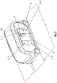
- the sliding door comprises two laterally sliding on the motor vehicle between a closed position and an open position sliding door 1, of which - as in Fig. 2 shown in the open position of one of the sliding door 1 in the direction of travel forward and the other sliding door 1 is moved to the rear.
- the two sliding door leaves 1 therefore together form a sliding door with two wings, which release a central access opening in the open position.
- Both sliding door leaves 1 are functionally the same and geometrically mirror-symmetrical.
- Each sliding door 1 has a lower part 2, wherein the lower part 2 in each case in the closed position of the sliding door at its upper edge 3 of the remaining sliding door is releasable and to its lower edge 5 is pivotally mounted, so that the lower parts 2 can be pivoted in the closed position of the sliding door in a ramp position in which both lower parts together form a ramp 6 (see Fig. 3 ).
- the lower parts 2 are separable from the remaining parts of the sliding door leaf 1 and pivotable at the lower edges 5, the lower parts must also be able to be released as far as necessary on the side edges 4 of other parts of the sliding door leaf 1.
- a release is only necessary insofar as the side edges 4 are not free anyway, because these form, for example, the conclusion of the sliding door leaf 1 or at least not attached to the remaining sliding door 1.
- each of the two sliding door leaves 1 also includes a respective upper part 7 of the sliding door leaf 1 - see in particular Fig. 2 -, Wherein the upper part 7 in the closed position of the sliding door at its lower edge 8 and optionally at its side edges 9 is detachable from the rest of the sliding door and is pivotally mounted on its upper edge 10, so that the respective upper part 7 in the closed position of the sliding door in a Roof position can be pivoted, in which both tops together form a roof 11 - see Fig. 3 ,
- the lower part 2 and the upper part 7 extend together over substantially the entire height of the door leaf 1. For example, only a narrow frame for supporting the pivotable lower parts 2 and upper parts 7 of the door leaf 1 remains, which opens and closes with the sliding door leaf 1 and not part of the lower part 2 or upper part 7 belongs.
- the upper edge 3 of the lower part 2 and the lower edge 8 of the upper part 7 can be fastened to each other and preferably locked.
Abstract
Ein Kraftfahrzeug umfassend eine Schiebetüre, wobei die Schiebetüre zumindest einen seitlich am Kraftfahrzeug zwischen einer Geschlossenstellung und einer Offenstellung verschiebbaren Schiebetürflügel (1) umfasst, wobei der Schiebetürflügel (1) einen Unterteil (2) des Schiebetürflügels (1) umfasst, wobei der Unterteil (2) in der Geschlossenstellung der Schiebetür an seiner Oberkante (3) und soweit erforderlich an seinen Seitenkanten (4) von der restlichen Schiebetür lösbar ist und an seiner Unterkante (5) schwenkbar gelagert ist, so dass der Unterteil (2) in der Geschlossenstellung der Schiebetür in eine Rampenstellung geschwenkt werden kann, in welcher der Unterteil (2) eine Rampe (6) bildet.A motor vehicle comprising a sliding door, the sliding door comprising at least one sliding door wing (1) displaceable laterally on the motor vehicle between a closed position and an open position, the sliding door wing (1) comprising a lower part (2) of the sliding door leaf (1), the lower part (2 ) in the closed position of the sliding door at its upper edge (3) and as far as necessary on its side edges (4) of the remaining sliding door is releasably and at its lower edge (5) is pivotally mounted, so that the lower part (2) in the closed position of the sliding door can be pivoted into a ramp position, in which the lower part (2) forms a ramp (6).
Description
Die vorliegende Erfindung betrifft ein Kraftfahrzeug umfassend eine Schiebetüre.The present invention relates to a motor vehicle comprising a sliding door.
Kraftfahrzeuge, wie Personenkraftwagen und Busse, können wie an sich bekannt mit Schiebetüren ausgestattet sein, so dass entweder ein Türflügel der Schiebetür seitlich in einer Fahrzeuglängsrichtung nach vorn oder nach hinten verschoben werden kann um die Türe zu öffnen, oder zwei seitliche Türflügel verschoben werden können, einer nach vorne und einer nach hinten, um die Tür zu öffnen.Motor vehicles, such as passenger cars and buses, can be equipped, as is known, with sliding doors, so that either a door leaf of the sliding door can be displaced laterally in a vehicle longitudinal direction forward or backward to open the door, or two lateral door leaves can be moved, one in front and one in the back to open the door.
Bekannt ist auch der Einsatz von Rampen um beispielsweise Rollstuhlfahrern den Zutritt in ein Kraftfahrzeug bei geöffneter Tür zu erleichtern. Hierzu können insbesondere im Kraftfahrzeug transportierte separate Rampenelemente bei geöffneter Tür auf einen Boden des Kraftfahrzeugs im Türbereich aufgelegt werden oder auch im Bodenbereich vormontierte Rampenteile ausgezogen oder ausgeschwenkt werden.Also known is the use of ramps for example, wheelchair users to facilitate access to a motor vehicle with the door open. For this purpose, in particular in the motor vehicle transported separate ramp elements can be placed with the door open on a floor of the motor vehicle in the door area or pulled out in the ground area pre-assembled ramp parts or swung.
Die
Es ist eine Aufgabe der Erfindung, ein Kraftfahrzeug umfassend eine Schiebetüre anzugeben, dass einen einfachen und effizienten Zutritt über eine Rampe ermöglicht.It is an object of the invention to provide a motor vehicle comprising a sliding door that allows easy and efficient access via a ramp.
Die Lösung der Aufgabe erfolgt durch ein Kraftfahrzeug umfassend eine Schiebetüre, wobei die Schiebetüre zumindest einen seitlich am Kraftfahrzeug zwischen einer Geschlossenstellung und einer Offenstellung verschiebbaren Schiebetürflügel umfasst, wobei der Schiebetürflügel einen Unterteil des Schiebetürflügels umfasst, wobei der Unterteil in der Geschlossenstellung der Schiebetür an seiner Oberkante und soweit erforderlich an seinen Seitenkanten von der restlichen Schiebetür lösbar ist und an seiner Unterkante schwenkbar gelagert ist, so dass der Unterteil in der Geschlossenstellung der Schiebetür in eine Rampenstellung geschwenkt werden kann, in welcher der Unterteil eine Rampe bildet.The object is achieved by a motor vehicle comprising a sliding door, the sliding door comprising at least one laterally sliding on the motor vehicle between a closed position and an open position sliding door, wherein the sliding door comprises a lower part of the sliding door leaf, wherein the lower part in the closed position of the sliding door at its upper edge and as far as necessary on its side edges of the remaining sliding door is releasable and is pivotally mounted on its lower edge, so that the lower part can be pivoted in the closed position of the sliding door in a ramp position in which the lower part forms a ramp.
Erfindungsgemäß ist eine Rampenfunktion direkt in einen Flügel einer Schiebetür eingebaut. Der selbe Schiebetürflügel kann also in üblicher Weise in Fahrzeuglängsrichtung verschoben werden, um einen Zutritt in das Kraftfahrzeug in einer Offenstellung freizugeben oder in einer Geschlossenstellung zu verschließen, und beinhaltet auch einen unteren Teil des Schiebetürflügels, den Unterteil, der an seiner Unterkante angeschlagen in eine Rampenstellung verschwenkt werden kann, so dass beispielsweise eine Zufahrt mit einem Rollstuhl über die Rampe ermöglicht wird. Diese Doppelnutzung des Schiebetürflügels ermöglicht eine besonders platzsparende Bauweise. Zudem kann der Zustieg und Ausstieg aus dem Kraftfahrzeug über einerseits die Schiebetürfunktion und andererseits die Rampenfunktion bequem erfolgen und die gewünschte Stellung des Schiebetürflügels beispielsweise auf Knopfdruck aktiviert werden.According to the invention a ramp function is installed directly in a wing of a sliding door. The same sliding door leaves can thus be moved in the usual way in the vehicle longitudinal direction to release access to the motor vehicle in an open position or to close in a closed position, and also includes a lower part of the sliding door, the lower part, struck at its lower edge in a ramp position can be pivoted, so for example a wheelchair access via the ramp is made possible. This double use of the sliding door leaves a particularly space-saving design. In addition, the approach and exit from the motor vehicle on the one hand, the sliding door function and on the other hand, the ramp function can be done easily and the desired position of the sliding door leaf, for example, activated at the touch of a button.
Der Unterteil kann beispielsweise die gesamte Breite des Schiebetürflügels einnehmen, so dass der Unterteil keine Seitenkanten oder eventuell nur eine Seitenkante umfasst, die vom restlichen Schiebetürflügel gelöst werden muss, um den Unterteil verschwenken zu können. Das Lösen der Seitenkanten bedeutet dabei, dass eine eventuelle Befestigung der Seitenkante am umgebenden Schiebetürflügel geöffnet wird, so dass ein Verschwenken des Unterteils allein ermöglicht wird. Wenn die Seitenkante ohnehin nicht an restlichen Teilen des Schiebetürflügel befestigt ist, ist ein Lösen der Seitenkante natürlich nicht erforderlich.The lower part can, for example, occupy the entire width of the sliding door leaf, so that the lower part does not include any side edges or possibly only one side edge, which must be released from the remaining sliding door leaf in order to pivot the lower part. The release of the side edges means that a possible attachment of the side edge is opened at the surrounding sliding door, so that pivoting of the lower part is made possible alone. If the side edge is not attached to any remaining parts of the sliding door leaf anyway, a release of the side edge is of course not required.
Der Unterteil kann auch fast die gesamte Breite des Schiebetürflügels einnehmen, so dass das Unterteil zwei Seitenkanten - eine in Fahrtrichtung vorne und eine in Fahrtrichtung hinten - umfasst, die wie oben beschrieben eventuell gelöst werden, so dass der Schiebetürflügel einen Rahmen ausbildet, der nicht zum verschwenkbaren Unterteil gehört.The lower part can also occupy almost the entire width of the sliding door wing, so that the lower part comprises two side edges - one in front and one in the rear direction of travel, which may be solved as described above, so that the sliding door leaf forms a frame that is not for pivotable lower part heard.
Das Unterteil kann beispielsweise fast die gesamte Höhe des Schiebetürflügels einnehmen, so dass im Bereich der Oberkante des Unterteils lediglich ein Rahmen des Schiebetürflügels nicht zum verschwenkbaren Unterteil gehört.The lower part can, for example, occupy almost the entire height of the sliding door leaf, so that in the region of the upper edge of the lower part only one frame of the sliding door leaf does not belong to the pivotable lower part.
Vorzugsweise umfasst der Schiebetürflügel einen Oberteil des Schiebetürflügels, wobei der Oberteil in der Geschlossenstellung der Schiebetür an seiner Unterkante und soweit erforderlich an seinen Seitenkanten von der restlichen Schiebetür lösbar ist und an seiner Oberkante schwenkbar gelagert ist, so dass der Oberteil in der Geschlossenstellung der Schiebetür in eine Dachstellung geschwenkt werden kann, in welcher das Oberteil ein Dach bildet. Durch Verwendung eines derartigen verschwenkbaren Oberteils kann auch der Unterteil kürzer ausgebildet werden und dennoch eine gute freie Höhe für den Zutritt über die Rampe in der Geschlossenstellung der Schiebetür erreicht werden.Preferably, the sliding door leaf comprises an upper part of the sliding door leaf, wherein the upper part in the closed position of the sliding door its lower edge and as far as necessary on its side edges of the remaining sliding door is releasable and is pivotally mounted on its upper edge, so that the upper part can be pivoted in the closed position of the sliding door in a roof position in which the upper part forms a roof. By using such a pivotable upper part and the lower part can be made shorter and still a good free height for access via the ramp in the closed position of the sliding door can be achieved.
Bevorzugt bilden der Unterteil und der Oberteil zusammen im Wesentlichen die gesamte Höhe des Türflügels, wobei auch ein nichtverschwenkbarer Rahmen oben und/oder unten am Schiebetürflügel verbleiben kann.Preferably, the lower part and the upper part together form substantially the entire height of the door leaf, whereby a non-swiveling frame can remain at the top and / or at the bottom of the sliding door leaf.
Bevorzugt besteht ein Schiebetürflügel ausschließlich aus einem Unterteil und einem schmalen Rahmenelement oder ausschließlich aus einem Unterteil und einem Oberteil und zusätzlich einem schmalen Rahmenelement, wobei das Rahmenelement ausschließlich oben und/oder unten oder auch zusätzlich an den Seiten von Unterteil bzw. Oberteil ausgebildet sein kann, also in Fahrtrichtung vorne und/oder hinten am Fahrzeug.A sliding door leaf preferably consists exclusively of a lower part and a narrow frame element or exclusively of a lower part and a upper part and additionally a narrow frame element, wherein the frame element may be formed exclusively above and / or below or additionally on the sides of lower part or upper part, So in the direction of travel front and / or rear of the vehicle.
Die Oberkante des Unterteils und die Unterkante des Oberteils können bevorzugt aneinander befestigt werden und vorzugsweise in der aneinander befestigten Stellung verriegelt werden.The upper edge of the lower part and the lower edge of the upper part may preferably be fastened to one another and preferably locked in the position fastened to one another.
Vorzugsweise umfasst die Schiebetüre zwei seitlich am Kraftfahrzeug zwischen einer Geschlossenstellung und einer Offenstellung verschiebbare Schiebetürflügel, wobei in der Offenstellung einer der Schiebetürflügel in Fahrtrichtung nach vorne und der andere Schiebetürflügel nach hinten verschoben ist. Beide Schiebetürflügel sind dann bevorzugt so ausgebildet wie zuvor beschrieben. Insbesondere kann jeder der beiden Schiebetürflügel jeweils einen Unterteil des Schiebetürflügels umfassen, wobei der Unterteil jeweils in der Geschlossenstellung der Schiebetür an seiner Oberkante und gegebenenfalls an seinen Seitenkanten von der restlichen Schiebetür lösbar ist und an seiner Unterkante schwenkbar gelagert ist, so dass die beiden Unterteile in der Geschlossenstellung der Schiebetür in eine Rampenstellung geschwenkt werden können. Die beiden Unterteile der Schiebetürflügel bilden in der Rampenstellung bevorzugt zusammen eine Rampe.Preferably, the sliding door comprises two laterally sliding on the motor vehicle between a closed position and an open position sliding door, wherein in the open position one of the sliding door is moved in the direction of travel forward and the other sliding door to the rear. Both sliding door leaves are then preferably formed Like previously described. In particular, each of the two sliding door leaves may each comprise a lower part of the sliding door leaf, wherein the lower part in each case in the closed position of the sliding door at its upper edge and optionally at its side edges of the remaining sliding door is releasable and is pivotally mounted at its lower edge, so that the two lower parts in the closed position of the sliding door can be pivoted to a ramp position. The two lower parts of the sliding door wings preferably form a ramp together in the ramp position.
Die in Fahrtrichtung hintere Seitenkante des vorderen Unterteils kann in der Rampenstellung an der vorderen Seitenkante des hinteren Unterteils befestigt sein, und insbesondere in dieser Befestigung verriegelt sein. Die beiden Unterteile sind dann in der Rampenstellung seitlich aneinander befestigt um eine gemeinsame Rampe zu bilden.The rear side edge of the front lower part in the direction of travel may be fixed in the ramp position on the front side edge of the rear lower part, and in particular locked in this attachment. The two lower parts are then fastened to each other in the ramp position laterally to form a common ramp.
Beide Schiebetürflügel können jeweils einen Oberteil des Schiebetürflügels umfassen, wobei der Oberteil jeweils in der Geschlossenstellung der Schiebetür an seiner Unterkante und gegebenenfalls an seinen Seitenkanten von der restlichen Schiebetür lösbar ist und an seiner Oberkante schwenkbar gelagert ist, so dass der jeweilige Oberteil in der Geschlossenstellung der Schiebetür in eine Dachstellung geschwenkt werden kann, in welcher beide Oberteile zusammen ein Dach bilden. Die beiden Oberteile können wieder seitlich verbunden sein, also aneinander befestigt oder auch verriegelt, um ein gemeinsames Dach zu bilden.Both sliding door leaves may each comprise an upper part of the sliding door leaf, wherein the upper part in the closed position of the sliding door at its lower edge and optionally at its side edges of the remaining sliding door is releasable and is pivotally mounted on its upper edge, so that the respective upper part in the closed position of Sliding door can be pivoted into a roof position in which both tops together form a roof. The two tops can again be connected laterally, that is attached to each other or locked to form a common roof.
Die Erfindung wird im Folgenden beispielhaft unter Bezugnahme auf die Zeichnungen beschrieben.
- Fig. 1
- ist eine schematische dreidimensionale Ansicht eines erfindungsgemäßen Kraftfahrzeugs umfassend eine Schiebetüre mit zwei Schiebetürflügeln, wobei sich die Schiebetüre in der Geschlossenstellung befindet.
- Fig. 2
- ist eine schematische dreidimensionale Ansicht eines Kraftfahrzeugs gemäß
Fig. 1 , wobei sich die Schiebetür in der Offenstellung befindet. - Fig. 3
- ist eine schematische dreidimensionale Ansicht eines Kraftfahrzeugs gemäß
Fig. 1 , wobei sich die Schiebetür in der Geschlossenstellung in der Rampenstellung befindet.
- Fig. 1
- is a schematic three-dimensional view of a motor vehicle according to the invention comprising a sliding door with two sliding door wings, wherein the sliding door is in the closed position.
- Fig. 2
- is a schematic three-dimensional view of a motor vehicle according to
Fig. 1 , wherein the sliding door is in the open position. - Fig. 3
- is a schematic three-dimensional view of a motor vehicle according to
Fig. 1 , wherein the sliding door is in the closed position in the ramp position.
In
Beide Schiebetürflügel 1 sind funktional gleich und geometrisch spiegelsymmetrisch ausgebildet. Jeder Schiebetürflügel 1 weist einen Unterteil 2 auf, wobei der Unterteil 2 jeweils in der Geschlossenstellung der Schiebetür an seiner Oberkante 3 von der restlichen Schiebetür lösbar ist und an seiner Unterkante 5 schwenkbar gelagert ist, so dass die Unterteile 2 in der Geschlossenstellung der Schiebetür in eine Rampenstellung geschwenkt werden können, in welcher beide Unterteile zusammen eine Rampe 6 bilden (siehe
Damit die Unterteile 2 von den restlichen Teilen der Schiebetürflügel 1 trennbar und an deren Unterkanten 5 schwenkbar werden, müssen die Unterteile auch soweit erforderlich an deren Seitenkanten 4 von anderen Teilen des Schiebetürflügels 1 gelöst werden können. Ein Lösen ist dabei nur insoweit nötig, als die Seitenkanten 4 nicht ohnehin frei stehen, weil diese beispielsweise den Abschluss des Schiebetürflügels 1 bilden oder jedenfalls nicht am restlichen Schiebetürflügel 1 befestigt sind.So that the lower parts 2 are separable from the remaining parts of the sliding door leaf 1 and pivotable at the
Ferner umfasst jeder der beiden Schiebetürflügel 1 auch jeweils einen Oberteil 7 des Schiebetürflügels 1 - siehe insbesondere
Der Unterteil 2 und der Oberteil 7 erstrecken sich zusammen über im Wesentlichen die gesamte Höhe des Türflügels 1. Dabei verbleibt beispielsweise lediglich ein schmaler Rahmen zur Lagerung der schwenkbaren Unterteile 2 und Oberteile 7 des Türflügels 1, der sich mit dem Schiebetürflügel 1 mit öffnet und schließt und nicht zum Unterteil 2 oder Oberteil 7 gehört.The lower part 2 and the upper part 7 extend together over substantially the entire height of the door leaf 1. For example, only a narrow frame for supporting the pivotable lower parts 2 and upper parts 7 of the door leaf 1 remains, which opens and closes with the sliding door leaf 1 and not part of the lower part 2 or upper part 7 belongs.
Die Oberkante 3 des Unterteils 2 und die Unterkante 8 des Oberteils 7 können aneinander befestigt und vorzugsweise verriegelt werden.The
In der Rampenstellung -
- 11
- Schiebetürflügelsliding wing
- 22
- Unterteillower part
- 33
- Oberkante UnterteilTop edge lower part
- 44
- Seitenkante UnterteilSide edge lower part
- 55
- Unterkante UnterteilLower edge lower part
- 66
- Ramperamp
- 77
- Oberteiltop
- 88th
- Unterkante OberteilLower edge upper part
- 99
- Seitenkante OberteilSide edge upper part
- 1010
- Oberkante OberteilTop edge upper part
- 1111
- Dachtop, roof
Claims (7)
dadurch gekennzeichnet, dass der Schiebetürflügel (1) einen Unterteil (2) des Schiebetürflügels (1) umfasst, wobei der Unterteil (2) in der Geschlossenstellung der Schiebetür an seiner Oberkante (3) und soweit erforderlich an seinen Seitenkanten (4) von der restlichen Schiebetür lösbar ist und an seiner Unterkante (5) schwenkbar gelagert ist, so dass der Unterteil (2) in der Geschlossenstellung der Schiebetür in eine Rampenstellung geschwenkt werden kann, in welcher der Unterteil (2) eine Rampe (6) bildet.Motor vehicle comprising a sliding door, wherein the sliding door comprises at least one laterally sliding on the motor vehicle between a closed position and an open position sliding door leaves (1),
characterized in that the sliding door leaf (1) comprises a lower part (2) of the sliding door leaf (1), wherein the lower part (2) in the closed position of the sliding door at its upper edge (3) and if necessary at its side edges (4) of the remaining Sliding door is detachable and is pivotally mounted on its lower edge (5), so that the lower part (2) can be pivoted in the closed position of the sliding door in a ramp position in which the lower part (2) forms a ramp (6).
dadurch gekennzeichnet, dass der Schiebetürflügel (1) einen Oberteil (7) des Schiebetürflügels (1) umfasst, wobei der Oberteil (7) in der Geschlossenstellung der Schiebetür an seiner Unterkante (8) und soweit erforderlich an seinen Seitenkanten (9) von der restlichen Schiebetür lösbar ist und an seiner Oberkante (10) schwenkbar gelagert ist, so dass der Oberteil in der Geschlossenstellung der Schiebetür in eine Dachstellung geschwenkt werden kann, in welcher das Oberteil ein Dach (11) bildet.Motor vehicle according to claim 1,
characterized in that the sliding door leaf (1) comprises an upper part (7) of the sliding door leaf (1), wherein the upper part (7) in the closed position of the sliding door at its lower edge (8) and if necessary at its side edges (9) of the remaining Sliding door is detachable and is pivotally mounted on its upper edge (10), so that the upper part can be pivoted in the closed position of the sliding door in a roof position in which the upper part forms a roof (11).
dadurch gekennzeichnet, dass der Unterteil (2) und der Oberteil (7) zusammen die gesamte Höhe des Türflügels (1) bilden.Motor vehicle according to claim 2,
characterized in that the lower part (2) and the upper part (7) together form the entire height of the door leaf (1).
dadurch gekennzeichnet, dass die Oberkante (3) des Unterteils (2) und die Unterkante (8) des Oberteils (7) aneinander befestigt und vorzugsweise verriegelt werden können.Motor vehicle according to claim 2 or 3,
characterized in that the upper edge (3) of the lower part (2) and the lower edge (8) of the upper part (7) are secured together and preferably can be locked.
dadurch gekennzeichnet, dass die Schiebetüre zwei seitlich am Kraftfahrzeug zwischen einer Geschlossenstellung und einer Offenstellung verschiebbare Schiebetürflügel (1) umfasst, wobei in der Offenstellung einer der Schiebetürflügel (1) in Fahrtrichtung nach vorne und der andere Schiebetürflügel (1) nach hinten verschoben ist, wobei beide Schiebetürflügel (1) jeweils einen Unterteil (2) des Schiebetürflügels (1) umfassen, wobei der Unterteil (2) jeweils in der Geschlossenstellung der Schiebetür an seiner Oberkante (3) und gegebenenfalls an seinen Seitenkanten (4) von der restlichen Schiebetür lösbar ist und an seiner Unterkante (5) schwenkbar gelagert ist, so dass die beiden Unterteile (2) in der Geschlossenstellung der Schiebetür in eine Rampenstellung geschwenkt werden können, in welcher beide Unterteile zusammen eine Rampe (6) bilden.Motor vehicle according to at least one of the preceding claims,
characterized in that the sliding door comprises two laterally sliding on the motor vehicle between a closed position and an open position sliding door (1), wherein in the open position of the sliding door (1) in the direction of travel forward and the other sliding door (1) is moved backwards, wherein both sliding door leaves (1) each comprise a lower part (2) of the sliding door leaf (1), wherein the lower part (2) in the closed position of the sliding door on its upper edge (3) and optionally on its side edges (4) from the remaining sliding door is solvable and is pivotally mounted on its lower edge (5), so that the two lower parts (2) can be pivoted in the closed position of the sliding door into a ramp position in which both lower parts together form a ramp (6).
dadurch gekennzeichnet , dass in der Rampenstellung die in Fahrtrichtung hintere Seitenkante (4) des vorderen Unterteils (2) an der vorderen Seitenkante (4) des hinteren Unterteils (2) befestigt, insbesondere verriegelt, ist.Motor vehicle according to claim 5,
characterized in that in the ramp position in the direction of travel rear side edge (4) of the front lower part (2) on the front side edge (4) of the rear lower part (2) attached, in particular locked, is.
dadurch gekennzeichnet , dass beide Schiebetürflügel (1) jeweils einen Oberteil (7) des Schiebetürflügels (1) umfassen, wobei der Oberteil (7) jeweils in der Geschlossenstellung der Schiebetür an seiner Unterkante (8) und gegebenenfalls an seinen Seitenkanten (9) von der restlichen Schiebetür lösbar ist und an seiner Oberkante (10) schwenkbar gelagert ist, so dass der jeweilige Oberteil (7) in der Geschlossenstellung der Schiebetür in eine Dachstellung geschwenkt werden kann, in welcher beide Oberteile zusammen ein Dach (11) bilden.Motor vehicle according to at least one of claims 5 or 6,
characterized in that both sliding door leaves (1) each comprise an upper part (7) of the sliding door leaf (1), wherein the upper part (7) in each case in the closed position of the sliding door at its lower edge (8) and optionally at its side edges (9) of the remaining sliding door is releasable and is pivotally mounted on its upper edge (10), so that the respective upper part (7) can be pivoted in the closed position of the sliding door in a roof position, in which both upper parts together form a roof (11).
Applications Claiming Priority (1)
| Application Number | Priority Date | Filing Date | Title |
|---|---|---|---|
| EP17208962 | 2017-12-20 |
Publications (2)
| Publication Number | Publication Date |
|---|---|
| EP3501467A1 true EP3501467A1 (en) | 2019-06-26 |
| EP3501467B1 EP3501467B1 (en) | 2020-01-22 |
Family
ID=60813617
Family Applications (1)
| Application Number | Title | Priority Date | Filing Date |
|---|---|---|---|
| EP18211293.8A Active EP3501467B1 (en) | 2017-12-20 | 2018-12-10 | Motor vehicle comprising a sliding door |
Country Status (1)
| Country | Link |
|---|---|
| EP (1) | EP3501467B1 (en) |
Cited By (9)
| Publication number | Priority date | Publication date | Assignee | Title |
|---|---|---|---|---|
| IT201900007977A1 (en) * | 2019-06-04 | 2020-12-04 | Iveco France Sas | PUBLIC TRANSPORT VEHICLE INCLUDING AN IMPROVED HOLD SYSTEM |
| DE102019135081A1 (en) * | 2019-08-28 | 2021-03-04 | Man Truck & Bus Se | Vehicle door construction with integrated ramp |
| DE102019132142A1 (en) * | 2019-11-27 | 2021-05-27 | Volkswagen Aktiengesellschaft | Vehicle with a vehicle door that can be used as a ramp |
| DE102020212484B3 (en) * | 2020-10-02 | 2021-07-08 | Volkswagen Aktiengesellschaft | Support structure for a vehicle and vehicle with such |
| DE102020204322A1 (en) | 2020-04-02 | 2021-10-07 | Volkswagen Aktiengesellschaft | Vehicle with a ramp arrangement |
| DE102020204674A1 (en) | 2020-04-14 | 2021-10-14 | Volkswagen Aktiengesellschaft | Vehicle with an in-vehicle ramp arrangement |
| WO2022084251A1 (en) * | 2020-10-19 | 2022-04-28 | Brose Fahrzeugteile Se & Co. Kommanditgesellschaft, Bamberg | Vehicle with platform unit on a body opening |
| WO2023009316A1 (en) * | 2021-07-29 | 2023-02-02 | Termson Management Llc | Body and closures |
| DE102021212984A1 (en) | 2021-11-18 | 2023-05-25 | Bode-Die Tür GmbH | Vehicle with a ramp part on a body opening |
Citations (3)
| Publication number | Priority date | Publication date | Assignee | Title |
|---|---|---|---|---|
| US5577793A (en) * | 1993-04-21 | 1996-11-26 | Kobasic; Richard A. | Multipurpose highway vehicle |
| US7322636B1 (en) * | 2007-01-05 | 2008-01-29 | Ford Global Technologies, Llc | Vehicle side-entry door assembly |
| EP3078520A1 (en) | 2015-04-09 | 2016-10-12 | Designquadrat Gbr | Vehicle door system |
-
2018
- 2018-12-10 EP EP18211293.8A patent/EP3501467B1/en active Active
Patent Citations (3)
| Publication number | Priority date | Publication date | Assignee | Title |
|---|---|---|---|---|
| US5577793A (en) * | 1993-04-21 | 1996-11-26 | Kobasic; Richard A. | Multipurpose highway vehicle |
| US7322636B1 (en) * | 2007-01-05 | 2008-01-29 | Ford Global Technologies, Llc | Vehicle side-entry door assembly |
| EP3078520A1 (en) | 2015-04-09 | 2016-10-12 | Designquadrat Gbr | Vehicle door system |
Cited By (10)
| Publication number | Priority date | Publication date | Assignee | Title |
|---|---|---|---|---|
| IT201900007977A1 (en) * | 2019-06-04 | 2020-12-04 | Iveco France Sas | PUBLIC TRANSPORT VEHICLE INCLUDING AN IMPROVED HOLD SYSTEM |
| EP3747679A1 (en) * | 2019-06-04 | 2020-12-09 | Iveco France S.A.S. | Public transport vehicle comprising an improved door system |
| DE102019135081A1 (en) * | 2019-08-28 | 2021-03-04 | Man Truck & Bus Se | Vehicle door construction with integrated ramp |
| DE102019132142A1 (en) * | 2019-11-27 | 2021-05-27 | Volkswagen Aktiengesellschaft | Vehicle with a vehicle door that can be used as a ramp |
| DE102020204322A1 (en) | 2020-04-02 | 2021-10-07 | Volkswagen Aktiengesellschaft | Vehicle with a ramp arrangement |
| DE102020204674A1 (en) | 2020-04-14 | 2021-10-14 | Volkswagen Aktiengesellschaft | Vehicle with an in-vehicle ramp arrangement |
| DE102020212484B3 (en) * | 2020-10-02 | 2021-07-08 | Volkswagen Aktiengesellschaft | Support structure for a vehicle and vehicle with such |
| WO2022084251A1 (en) * | 2020-10-19 | 2022-04-28 | Brose Fahrzeugteile Se & Co. Kommanditgesellschaft, Bamberg | Vehicle with platform unit on a body opening |
| WO2023009316A1 (en) * | 2021-07-29 | 2023-02-02 | Termson Management Llc | Body and closures |
| DE102021212984A1 (en) | 2021-11-18 | 2023-05-25 | Bode-Die Tür GmbH | Vehicle with a ramp part on a body opening |
Also Published As
| Publication number | Publication date |
|---|---|
| EP3501467B1 (en) | 2020-01-22 |
Similar Documents
| Publication | Publication Date | Title |
|---|---|---|
| EP3501467B1 (en) | Motor vehicle comprising a sliding door | |
| DE60128199T2 (en) | delivery trucks | |
| DE102016202395B3 (en) | Passenger vehicle with a side door | |
| DE1183388B (en) | Cab appearance, especially for commercial vehicles | |
| DE2620683C3 (en) | Entrance arrangement for a local transport vehicle, in particular a rail vehicle | |
| DE102005059413A1 (en) | Hinge for door of motor vehicle, has first fixing element and second fixing element, whereby hinge makes movement of door in arbitrary positions, comparable to robot arm | |
| DE102015012144A1 (en) | Fastening device for storing and moving at least one vehicle door on a motor vehicle | |
| DE4008145C2 (en) | ||
| DE3537304A1 (en) | STRUCTURE FOR CARS | |
| DE102015210564A1 (en) | Vehicle with at least one window opening for a window pane | |
| EP1752325B1 (en) | Roof system for a car | |
| DE202009007273U1 (en) | Passenger cars | |
| DE102019124071A1 (en) | Vehicle with folding sunroof and retractable rear window | |
| DE102007028283A1 (en) | Omnibus i.e. coach, has two folding doors provided at rear end serving as emergency exits, part of last seat row detachable with opened door and hauled from inside, and emergency chute connecting corridor section with base lying outside | |
| DE10219394B4 (en) | Tailgate for motor vehicles with a movably held tailgate part | |
| EP1671873B1 (en) | Device for releasably fastening a structure which is pivotably mounted relative to a support element | |
| DE102019132138B4 (en) | Vehicle and multifunctional vehicle door for one vehicle | |
| DE2927180A1 (en) | Luggage space for hatchback motor car - has central cover with pivoted supports and hinged side flaps over wheel arches | |
| DE202006008079U1 (en) | Retractable access ramp for public transport vehicles | |
| DE4200300C2 (en) | Passenger car with wing roof | |
| DE4328886C2 (en) | Cabriolet with a rear storage space | |
| EP3606806B1 (en) | Rear spolier for a vehicle | |
| DE102007033646A1 (en) | Driver's cab of a vehicle | |
| DE3814628C2 (en) | ||
| DE10062156A1 (en) | Vehicle roof has rear element that can be moved from closed position with rear edge above level of fixed roof wall into spoiler position |
Legal Events
| Date | Code | Title | Description |
|---|---|---|---|
| PUAI | Public reference made under article 153(3) epc to a published international application that has entered the european phase |
Free format text: ORIGINAL CODE: 0009012 |
|
| STAA | Information on the status of an ep patent application or granted ep patent |
Free format text: STATUS: THE APPLICATION HAS BEEN PUBLISHED |
|
| STAA | Information on the status of an ep patent application or granted ep patent |
Free format text: STATUS: REQUEST FOR EXAMINATION WAS MADE |
|
| AK | Designated contracting states |
Kind code of ref document: A1 Designated state(s): AL AT BE BG CH CY CZ DE DK EE ES FI FR GB GR HR HU IE IS IT LI LT LU LV MC MK MT NL NO PL PT RO RS SE SI SK SM TR |
|
| AX | Request for extension of the european patent |
Extension state: BA ME |
|
| 17P | Request for examination filed |
Effective date: 20190523 |
|
| RBV | Designated contracting states (corrected) |
Designated state(s): AL AT BE BG CH CY CZ DE DK EE ES FI FR GB GR HR HU IE IS IT LI LT LU LV MC MK MT NL NO PL PT RO RS SE SI SK SM TR |
|
| RIC1 | Information provided on ipc code assigned before grant |
Ipc: B60J 5/04 20060101ALI20190816BHEP Ipc: A61G 3/06 20060101AFI20190816BHEP |
|
| GRAP | Despatch of communication of intention to grant a patent |
Free format text: ORIGINAL CODE: EPIDOSNIGR1 |
|
| STAA | Information on the status of an ep patent application or granted ep patent |
Free format text: STATUS: GRANT OF PATENT IS INTENDED |
|
| INTG | Intention to grant announced |
Effective date: 20190927 |
|
| GRAS | Grant fee paid |
Free format text: ORIGINAL CODE: EPIDOSNIGR3 |
|
| GRAA | (expected) grant |
Free format text: ORIGINAL CODE: 0009210 |
|
| STAA | Information on the status of an ep patent application or granted ep patent |
Free format text: STATUS: THE PATENT HAS BEEN GRANTED |
|
| AK | Designated contracting states |
Kind code of ref document: B1 Designated state(s): AL AT BE BG CH CY CZ DE DK EE ES FI FR GB GR HR HU IE IS IT LI LT LU LV MC MK MT NL NO PL PT RO RS SE SI SK SM TR |
|
| REG | Reference to a national code |
Ref country code: GB Ref legal event code: FG4D Free format text: NOT ENGLISH |
|
| REG | Reference to a national code |
Ref country code: CH Ref legal event code: EP |
|
| REG | Reference to a national code |
Ref country code: AT Ref legal event code: REF Ref document number: 1226462 Country of ref document: AT Kind code of ref document: T Effective date: 20200215 |
|
| REG | Reference to a national code |
Ref country code: IE Ref legal event code: FG4D Free format text: LANGUAGE OF EP DOCUMENT: GERMAN |
|
| REG | Reference to a national code |
Ref country code: DE Ref legal event code: R096 Ref document number: 502018000663 Country of ref document: DE |
|
| REG | Reference to a national code |
Ref country code: NL Ref legal event code: MP Effective date: 20200122 |
|
| REG | Reference to a national code |
Ref country code: LT Ref legal event code: MG4D |
|
| PG25 | Lapsed in a contracting state [announced via postgrant information from national office to epo] |
Ref country code: PT Free format text: LAPSE BECAUSE OF FAILURE TO SUBMIT A TRANSLATION OF THE DESCRIPTION OR TO PAY THE FEE WITHIN THE PRESCRIBED TIME-LIMIT Effective date: 20200614 Ref country code: NL Free format text: LAPSE BECAUSE OF FAILURE TO SUBMIT A TRANSLATION OF THE DESCRIPTION OR TO PAY THE FEE WITHIN THE PRESCRIBED TIME-LIMIT Effective date: 20200122 Ref country code: FI Free format text: LAPSE BECAUSE OF FAILURE TO SUBMIT A TRANSLATION OF THE DESCRIPTION OR TO PAY THE FEE WITHIN THE PRESCRIBED TIME-LIMIT Effective date: 20200122 Ref country code: RS Free format text: LAPSE BECAUSE OF FAILURE TO SUBMIT A TRANSLATION OF THE DESCRIPTION OR TO PAY THE FEE WITHIN THE PRESCRIBED TIME-LIMIT Effective date: 20200122 Ref country code: NO Free format text: LAPSE BECAUSE OF FAILURE TO SUBMIT A TRANSLATION OF THE DESCRIPTION OR TO PAY THE FEE WITHIN THE PRESCRIBED TIME-LIMIT Effective date: 20200422 |
|
| PG25 | Lapsed in a contracting state [announced via postgrant information from national office to epo] |
Ref country code: IS Free format text: LAPSE BECAUSE OF FAILURE TO SUBMIT A TRANSLATION OF THE DESCRIPTION OR TO PAY THE FEE WITHIN THE PRESCRIBED TIME-LIMIT Effective date: 20200522 Ref country code: SE Free format text: LAPSE BECAUSE OF FAILURE TO SUBMIT A TRANSLATION OF THE DESCRIPTION OR TO PAY THE FEE WITHIN THE PRESCRIBED TIME-LIMIT Effective date: 20200122 Ref country code: LV Free format text: LAPSE BECAUSE OF FAILURE TO SUBMIT A TRANSLATION OF THE DESCRIPTION OR TO PAY THE FEE WITHIN THE PRESCRIBED TIME-LIMIT Effective date: 20200122 Ref country code: BG Free format text: LAPSE BECAUSE OF FAILURE TO SUBMIT A TRANSLATION OF THE DESCRIPTION OR TO PAY THE FEE WITHIN THE PRESCRIBED TIME-LIMIT Effective date: 20200422 Ref country code: HR Free format text: LAPSE BECAUSE OF FAILURE TO SUBMIT A TRANSLATION OF THE DESCRIPTION OR TO PAY THE FEE WITHIN THE PRESCRIBED TIME-LIMIT Effective date: 20200122 Ref country code: GR Free format text: LAPSE BECAUSE OF FAILURE TO SUBMIT A TRANSLATION OF THE DESCRIPTION OR TO PAY THE FEE WITHIN THE PRESCRIBED TIME-LIMIT Effective date: 20200423 |
|
| REG | Reference to a national code |
Ref country code: DE Ref legal event code: R097 Ref document number: 502018000663 Country of ref document: DE |
|
| PG25 | Lapsed in a contracting state [announced via postgrant information from national office to epo] |
Ref country code: DK Free format text: LAPSE BECAUSE OF FAILURE TO SUBMIT A TRANSLATION OF THE DESCRIPTION OR TO PAY THE FEE WITHIN THE PRESCRIBED TIME-LIMIT Effective date: 20200122 Ref country code: EE Free format text: LAPSE BECAUSE OF FAILURE TO SUBMIT A TRANSLATION OF THE DESCRIPTION OR TO PAY THE FEE WITHIN THE PRESCRIBED TIME-LIMIT Effective date: 20200122 Ref country code: SM Free format text: LAPSE BECAUSE OF FAILURE TO SUBMIT A TRANSLATION OF THE DESCRIPTION OR TO PAY THE FEE WITHIN THE PRESCRIBED TIME-LIMIT Effective date: 20200122 Ref country code: ES Free format text: LAPSE BECAUSE OF FAILURE TO SUBMIT A TRANSLATION OF THE DESCRIPTION OR TO PAY THE FEE WITHIN THE PRESCRIBED TIME-LIMIT Effective date: 20200122 Ref country code: LT Free format text: LAPSE BECAUSE OF FAILURE TO SUBMIT A TRANSLATION OF THE DESCRIPTION OR TO PAY THE FEE WITHIN THE PRESCRIBED TIME-LIMIT Effective date: 20200122 Ref country code: RO Free format text: LAPSE BECAUSE OF FAILURE TO SUBMIT A TRANSLATION OF THE DESCRIPTION OR TO PAY THE FEE WITHIN THE PRESCRIBED TIME-LIMIT Effective date: 20200122 Ref country code: CZ Free format text: LAPSE BECAUSE OF FAILURE TO SUBMIT A TRANSLATION OF THE DESCRIPTION OR TO PAY THE FEE WITHIN THE PRESCRIBED TIME-LIMIT Effective date: 20200122 Ref country code: SK Free format text: LAPSE BECAUSE OF FAILURE TO SUBMIT A TRANSLATION OF THE DESCRIPTION OR TO PAY THE FEE WITHIN THE PRESCRIBED TIME-LIMIT Effective date: 20200122 |
|
| PLBE | No opposition filed within time limit |
Free format text: ORIGINAL CODE: 0009261 |
|
| STAA | Information on the status of an ep patent application or granted ep patent |
Free format text: STATUS: NO OPPOSITION FILED WITHIN TIME LIMIT |
|
| 26N | No opposition filed |
Effective date: 20201023 |
|
| PG25 | Lapsed in a contracting state [announced via postgrant information from national office to epo] |
Ref country code: IT Free format text: LAPSE BECAUSE OF FAILURE TO SUBMIT A TRANSLATION OF THE DESCRIPTION OR TO PAY THE FEE WITHIN THE PRESCRIBED TIME-LIMIT Effective date: 20200122 |
|
| PG25 | Lapsed in a contracting state [announced via postgrant information from national office to epo] |
Ref country code: PL Free format text: LAPSE BECAUSE OF FAILURE TO SUBMIT A TRANSLATION OF THE DESCRIPTION OR TO PAY THE FEE WITHIN THE PRESCRIBED TIME-LIMIT Effective date: 20200122 |
|
| PG25 | Lapsed in a contracting state [announced via postgrant information from national office to epo] |
Ref country code: MC Free format text: LAPSE BECAUSE OF FAILURE TO SUBMIT A TRANSLATION OF THE DESCRIPTION OR TO PAY THE FEE WITHIN THE PRESCRIBED TIME-LIMIT Effective date: 20200122 |
|
| REG | Reference to a national code |
Ref country code: BE Ref legal event code: MM Effective date: 20201231 |
|
| PG25 | Lapsed in a contracting state [announced via postgrant information from national office to epo] |
Ref country code: LU Free format text: LAPSE BECAUSE OF NON-PAYMENT OF DUE FEES Effective date: 20201210 Ref country code: IE Free format text: LAPSE BECAUSE OF NON-PAYMENT OF DUE FEES Effective date: 20201210 |
|
| PG25 | Lapsed in a contracting state [announced via postgrant information from national office to epo] |
Ref country code: TR Free format text: LAPSE BECAUSE OF FAILURE TO SUBMIT A TRANSLATION OF THE DESCRIPTION OR TO PAY THE FEE WITHIN THE PRESCRIBED TIME-LIMIT Effective date: 20200122 Ref country code: MT Free format text: LAPSE BECAUSE OF FAILURE TO SUBMIT A TRANSLATION OF THE DESCRIPTION OR TO PAY THE FEE WITHIN THE PRESCRIBED TIME-LIMIT Effective date: 20200122 Ref country code: CY Free format text: LAPSE BECAUSE OF FAILURE TO SUBMIT A TRANSLATION OF THE DESCRIPTION OR TO PAY THE FEE WITHIN THE PRESCRIBED TIME-LIMIT Effective date: 20200122 |
|
| PG25 | Lapsed in a contracting state [announced via postgrant information from national office to epo] |
Ref country code: MK Free format text: LAPSE BECAUSE OF FAILURE TO SUBMIT A TRANSLATION OF THE DESCRIPTION OR TO PAY THE FEE WITHIN THE PRESCRIBED TIME-LIMIT Effective date: 20200122 Ref country code: AL Free format text: LAPSE BECAUSE OF FAILURE TO SUBMIT A TRANSLATION OF THE DESCRIPTION OR TO PAY THE FEE WITHIN THE PRESCRIBED TIME-LIMIT Effective date: 20200122 |
|
| PG25 | Lapsed in a contracting state [announced via postgrant information from national office to epo] |
Ref country code: BE Free format text: LAPSE BECAUSE OF NON-PAYMENT OF DUE FEES Effective date: 20201231 |
|
| REG | Reference to a national code |
Ref country code: CH Ref legal event code: PL |
|
| REG | Reference to a national code |
Ref country code: DE Ref legal event code: R081 Ref document number: 502018000663 Country of ref document: DE Owner name: MAGNA STEYR FAHRZEUGTECHNIK GMBH & CO KG, AT Free format text: FORMER OWNER: MAGNA STEYR FAHRZEUGTECHNIK AG & CO KG, GRAZ, AT |
|
| PG25 | Lapsed in a contracting state [announced via postgrant information from national office to epo] |
Ref country code: LI Free format text: LAPSE BECAUSE OF NON-PAYMENT OF DUE FEES Effective date: 20211231 Ref country code: CH Free format text: LAPSE BECAUSE OF NON-PAYMENT OF DUE FEES Effective date: 20211231 |
|
| PG25 | Lapsed in a contracting state [announced via postgrant information from national office to epo] |
Ref country code: SI Free format text: LAPSE BECAUSE OF FAILURE TO SUBMIT A TRANSLATION OF THE DESCRIPTION OR TO PAY THE FEE WITHIN THE PRESCRIBED TIME-LIMIT Effective date: 20200122 |
|
| PGFP | Annual fee paid to national office [announced via postgrant information from national office to epo] |
Ref country code: GB Payment date: 20231220 Year of fee payment: 6 |
|
| PGFP | Annual fee paid to national office [announced via postgrant information from national office to epo] |
Ref country code: FR Payment date: 20231222 Year of fee payment: 6 Ref country code: DE Payment date: 20231214 Year of fee payment: 6 |