EP3499132A1 - Führungsvorrichtung zur führung eines gutträgers - Google Patents
Führungsvorrichtung zur führung eines gutträgers Download PDFInfo
- Publication number
- EP3499132A1 EP3499132A1 EP18209064.7A EP18209064A EP3499132A1 EP 3499132 A1 EP3499132 A1 EP 3499132A1 EP 18209064 A EP18209064 A EP 18209064A EP 3499132 A1 EP3499132 A1 EP 3499132A1
- Authority
- EP
- European Patent Office
- Prior art keywords
- guide
- housing
- pivot
- guide device
- arms
- Prior art date
- Legal status (The legal status is an assumption and is not a legal conclusion. Google has not performed a legal analysis and makes no representation as to the accuracy of the status listed.)
- Granted
Links
Images




Classifications
-
- F—MECHANICAL ENGINEERING; LIGHTING; HEATING; WEAPONS; BLASTING
- F24—HEATING; RANGES; VENTILATING
- F24C—DOMESTIC STOVES OR RANGES ; DETAILS OF DOMESTIC STOVES OR RANGES, OF GENERAL APPLICATION
- F24C15/00—Details
- F24C15/16—Shelves, racks or trays inside ovens; Supports therefor
- F24C15/162—Co-operating with a door, e.g. operated by the door
-
- F—MECHANICAL ENGINEERING; LIGHTING; HEATING; WEAPONS; BLASTING
- F24—HEATING; RANGES; VENTILATING
- F24C—DOMESTIC STOVES OR RANGES ; DETAILS OF DOMESTIC STOVES OR RANGES, OF GENERAL APPLICATION
- F24C15/00—Details
- F24C15/16—Shelves, racks or trays inside ovens; Supports therefor
- F24C15/168—Shelves, racks or trays inside ovens; Supports therefor with telescopic rail systems
-
- A—HUMAN NECESSITIES
- A47—FURNITURE; DOMESTIC ARTICLES OR APPLIANCES; COFFEE MILLS; SPICE MILLS; SUCTION CLEANERS IN GENERAL
- A47B—TABLES; DESKS; OFFICE FURNITURE; CABINETS; DRAWERS; GENERAL DETAILS OF FURNITURE
- A47B57/00—Cabinets, racks or shelf units, characterised by features for adjusting shelves or partitions
- A47B57/06—Cabinets, racks or shelf units, characterised by features for adjusting shelves or partitions with means for adjusting the height of the shelves
-
- F—MECHANICAL ENGINEERING; LIGHTING; HEATING; WEAPONS; BLASTING
- F24—HEATING; RANGES; VENTILATING
- F24C—DOMESTIC STOVES OR RANGES ; DETAILS OF DOMESTIC STOVES OR RANGES, OF GENERAL APPLICATION
- F24C15/00—Details
- F24C15/02—Doors specially adapted for stoves or ranges
- F24C15/023—Mounting of doors, e.g. hinges, counterbalancing
-
- F—MECHANICAL ENGINEERING; LIGHTING; HEATING; WEAPONS; BLASTING
- F24—HEATING; RANGES; VENTILATING
- F24C—DOMESTIC STOVES OR RANGES ; DETAILS OF DOMESTIC STOVES OR RANGES, OF GENERAL APPLICATION
- F24C15/00—Details
- F24C15/16—Shelves, racks or trays inside ovens; Supports therefor
Definitions
- the invention relates to a guide device for guiding a Gutmois in a housing, with at least two guide units, each attached to the housing with transverse spacing on the one hand to the housing and on the other hand coupled to the crop and the goods carrier by a movement between an inserted operating position and an at least partially lead the pull out position pulled out of the housing.
- the object of the invention is therefore to provide a guide device of the type mentioned above, with which it is guided at least one good carrier reliable and reliable between an operating position and an extended pull-out position.
- the guide device is characterized in that a synchronization device for synchronizing the movement of the guide units in the movement of the coupled to the guide units Gutmés is present.
- the synchronization unit thus ensures the synchronization of the guide units when removing the Gutmés, whereby an inclination of the Gutieris or tilting on side walls of the housing is avoided.
- the guide units are fastened by means of fastening means on a rear wall of the housing.
- fastening means on a rear wall of the housing.
- an attachment in both directions of the rear wall middle portion of the rear wall is provided.
- the guide units each have a guide rod consisting of a plurality of guide arms, which is movable in the manner of a concertina and thereby guides the goods carrier between the operating and Ausziehposition.
- a telescopic guide conceivable, are provided in the linear telescopically telescoping arms.
- the guide arms prefferably be designed as swivel arms which are pivotally connected to one another and pivotable on the upper side and / or the good-carrier-side pivot axes.
- the guide linkage in each case two pivot arms, of which a first pivot arm about a housing-side first pivot axis and a second pivot arm about a good carrier side second pivot axis is pivotally mounted and wherein the two pivot arms are pivotally connected to each other via a third pivot axis.
- the guide rods can thus each form a knee joint with such a configuration.
- the synchronization device has synchronization means via which the guide units are positively coupled together. A movement of a guide unit is thus inevitably transferred into a movement of the other guide unit, so that the guide units in the movement between the operating and the pull-out of the Gutieris are in synchronization.
- the guide units are coupled by means of coupling means to a coupling interface with the product carrier, wherein the synchronization means are arranged in the region of the coupling interface.
- the synchronization means on the one hand on the good carrier side guide arm, in particular pivot arm, a guide unit and on the other hand on good carrier side guide arm, in particular pivot arm, the other guide unit arranged.
- these synchronization means are expediently arranged on the good carrier side pivot axes.
- the synchronization means are designed as toothed segments, toothed racks, threaded rods, cables and / or belts.
- synchronization means are arranged on the good carrier side pivot arm in the guide unit, such that they are in meshing engagement with each other.
- the coupling means for coupling the guide unit to the product carrier are constructed as a bulkhead which is movably mounted by means of the guide units between an operating position located in the region of the rear wall and a closure position pulled out in the region of a housing opening of the housing.
- the invention further comprises a heating device, in particular a furnace, with a housing enclosing a heatable interior, wherein the interior is bounded on the rear side by a rear wall and on the front by a door which closes an access to the interior permitting housing opening at a closed position, wherein in the housing at least received after opening the door from the housing removable Gutong for heating the good, which is characterized by a guide device according to one of claims 1 to 11.
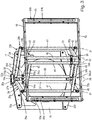
- FIGS. 1 to 7 show preferred embodiment of the guide device 11 according to the invention when used on a heating device 12 in the form of a baking oven. It would also be conceivable to use the guide device 11 in other heating devices 12, for example in a steamer or a microwave.
- the oven has a housing 13 which is cuboid in the example.
- the housing 13 encloses a heatable interior 14, which is bounded on the rear side by a rear wall 15 and on the front side by a door 16.
- the door 16 closes in a closed position access to the interior 14.
- the door is designed as a flap and can be folded down when opening forward down.
- the housing has two opposite side walls 17a, 17b, a bottom 18 and a top wall 19 opposite thereto.
- the goods carrier is designed as a food support, for example in the form of a baking tray or grate.
- the creditor is according to FIG. 1 by way of example in the form of a baking sheet, which has a support section 21 and a raised edge section 22 which delimits the support section all around.
- the guide device 11 has two guide units 23a, 23b, which are each attached to the housing 13 with transverse spacing on the one hand and on the other hand coupled to the crop support 20 and the goods by a movement movement between an inserted operating position 24 (FIG. FIG. 4 ) and an at least partially pulled out of the housing 13 pull-out position 25 lead.
- the guide units 23a, 23b each have a consisting of a plurality of guide arms guide linkage 26a, 26b, which is movable in the manner of a concertina, thereby guiding the crop support 20 between the operating and the pull-25.
- two guide units 23a, 23b are provided, each consisting of guide arms and each having a guide rod 26a, 26b, wherein the guide rods together form a kind of accordion guide.
- the guide rods 26a, 26b each have two pivot arms 27a, 27b; 28a, 28b, of which a first pivot arm 27a, 28a about a housing-side first pivot axis 29 and a second pivot arm 27b, 28b is pivotally mounted about a good carrier-side pivot axis 30.
- the two pivot arms 27a, 27b; 28a, 28b of a respective guide linkage 26a, 26b are over a third Swivel axis 31, which could also be referred to as a connection joint, pivotally connected to each other.
- the two guide rods 26a, 26b are fastened by means of fastening means on the rear wall 15 of the housing 13 of the oven.
- the attachment means include an upper yoke 32a and a lower yoke 32b respectively secured to the rear wall 15 of the housing 13, but the upper yoke 32a in the region of the upper wall 19 and the lower yoke 32b in the region of the bottom 18 of the housing, respectively the rear wall 15.
- the two yokes 32a, 32b extend substantially over the entire width of the rear wall 15th
- an upper swivel arm support 33a is attached to the upper yoke 32a and a lower swivel arm support 33b is attached to the lower yoke 32b, pointing towards the inner space 14 at the front of the associated yokes 32a, 32b.
- each lugs 34 a, 34 b are provided which protrude from the front of the respective yoke 32 a, 32 b forward toward the interior 14.
- the upper Schwenkachslic 33a sitting on the upper nose 34a, while the lower Schwenkarmarni 33b is overlapped by the lower nose 34b.
- the Schwenkarm portions 33a, 33b each have two mutually transverse bearing openings 35a, 35b; 36a, 36b, of which first bearing openings 35a, 36a on the upper and lower Schwenkarmyes 33a, 33b are aligned with each other and forms a receptacle for a vertical strut 37 of the first pivot arm 27a of the first guide linkage 26a.
- the vertical strut 37 is running The housing-side first pivot axis 29.
- the two Schwenkarmarrin 33a, 33b second bearing apertures 35b, 36b also aligned and recordings for another vertical strut 38 of the first pivot arm 28a of the second guide linkage 26b forms.
- the housing-side first pivot axis 29 of the first pivot arm of the second guide linkage 26b runs.
- the two first pivot arms 27a, 28a of the two guide rods 26a, 26b constructed by vertical and horizontal struts.
- the above-mentioned vertical struts 37, 38 are rotatably arranged in the associated bearing openings 35a, 35b and 36a, 36b.
- the two first pivot arms 27a, 28a each have an upper horizontal strut 39, each projecting from the vertical struts 37, 38 obliquely forward and are rigidly connected to the associated vertical struts 37, 38. Further, the first pivot arms 27a, 28a still have a lower horizontal strut 40, which is arranged parallel to the upper horizontal strut 39 and also rigid with the associated vertical struts 37, 38 is formed.
- the upper horizontal struts 39 and the lower horizontal struts 40 of the two pivot arms 27a, 28a are connected to each other at their free ends by a connecting strut 41, which is also designed as a vertical strut.
- the connecting strut 41 is on the one hand pivotally mounted on the upper horizontal strut and on the other hand pivotally mounted on the lower horizontal strut 40, whereby the third pivot axis 31 is formed.
- the respective connecting struts 41 in turn extend an upper and a lower horizontal strut 42, 43, which belong to the respective second pivot arms 27b, 28b of the guide rods 26a, 26b.
- the upper and lower horizontal struts 42, 43 are rigidly arranged on the connecting struts 41 and extend in contrast to the other upper and lower horizontal struts 39, 40 from outside to inside, so that the horizontal struts 39, 40, 42, 43 form the overall shape of a rhombus.
- the upper and lower horizontal struts 42, 43 of the respective second pivot arms 27b, 28b are rigidly connected to vertical struts 44, 45, which in turn are pivotally mounted on a bulkhead 46.
- the bulkhead 46 is disposed in the interior 14 and is movably guided via the guide device 11 between an operating position located in the region of the rear wall 15 and a withdrawn in the region of a housing opening 47, the housing opening 47 substantially completely occlusive closure position.
- the bulkhead 46 comprises a frame 49 which has an upper and a lower horizontally extending frame part 49, 50.
- the two vertical struts 44, 45 are on the one hand rotatably mounted on the upper and on the other hand rotatably mounted on the lower frame part 49, 50.
- the guide device 11 further comprises a synchronization device 51 for synchronizing the movement of the guide units 23a, 23b during the movement of the goods carrier 20 coupled to the guide units 23a, 23b.
- the two vertical struts 37, 38 form a first coupling interface 52 in the region of the rear wall 15 of the housing 13, while the two vertical struts 44, 45 form a second coupling interface 53 in the region of the bulkhead 46, via which the guide units 23 a, 23b are coupled, on the one hand, to the oven rear wall and, on the other hand, to the product carrier 20.
- the synopsis of Figures 3 . 4 . 5 and 6 shows the synchronization means 51 synchronization means over which the guide units 23a, 23b are positively coupled together.
- the synchronization means are exemplary in the form of toothed segments 54a, 54b; 55a, 55b.
- the first toothed segments 54a, 55a each have a cylindrical base portion 56 with a central through-opening 57, the cylindrical base portion 56 having a radially extending radial slot 58 through which mounting from the side of the associated vertical struts 37, 38 is possible.
- the radial slot 58 thus enables a lateral insertion of the toothed segments 54a, 55a to the vertical strut 37, 38.
- the two legs, the cylindrical base portion, which are separated by the radial slot 58, connected to each other by means of a fastening screw 59, that is tightening the fastening screw can narrow the radial slot 58, whereby the previously introduced toothed segment 54a, 55a in the desired Height along the vertical strut 37, 38 is fixed.
- the cylindrical base portion 56 has on its outer surface a tooth portion 60 with a row of teeth in the circumferential direction successively arranged teeth 61.
- the tooth portions 60 mesh with the teeth of the first toothed segment 54a on the first pivot axis 27a of the first guide linkage 26a Tooth portion or the teeth 61 on the first toothed segment 55a of the first pivot arm 28a of the second guide linkage 26b.
- two mutually engaged toothed segments 54b, 55b which are identical to the above-described toothed segments 54a, 55a, are also provided on the second coupling interface 53.
- the further toothed segments 54b, 55b are located in the region of the lower horizontal sections 43.
- the toothed sections mesh with the teeth 61 of the one toothed segment 54b on the second pivoting arm 27b of the first guide linkage 26a with the tooth sections or the teeth 61 of the second pivot arm 28b of the second guide linkage 26b.
- the bulkhead 46 is coupled by coupling means with the at least one crop rack 20, which is exemplified in the form of a baking sheet such that the bulkhead 46 is movable by pulling the Gutmés 20 of the operating in the closed position 48.
- the coupling means comprise at least one hook element 62 and at least one hook holder 63 for releasably holding the at least one hook element.
- the hook brackets 63 each include a support slot 64 extending in the height direction of the bulkhead, and suspension members superimposed with height clearance in the height direction 65, which enforce the slot width of the associated mounting slot. The hook elements 62 or hooks on the back of the baking sheet can then be hung in the associated suspension members 65 at the desired height on the bulkhead.
- FIG. 4 shows the bulkhead 46 and the goods carrier 20 coupled thereto in the form of the baking tray in a rear operating position 24, in which the bulkhead 46 is disposed near the rear wall 15 of the housing 13.
- the two guide rods 26a, 26b are maximally folded, wherein the two pivot axes 31 on the first guide linkage 26a and the second guide linkage 26b outside the outer ends of the yokes 32a, 32b.
- the connecting struts 37, 38 on the housing-side first coupling interface 52 and the vertical struts 44, 45 on the second good carrier-side coupling interface 53 are aligned with minimal distance from each other.
- the door 16 After completing a cooking process located on the baking tray Garguts the door 16 is opened and the baking sheet is pulled out in its pull-out position 25. In this case, the bulkhead 46 moves forward and closes the housing opening 47 substantially completely.
- the two guide rods 26a, 26b are unfolded, so that the two coupling interfaces 52, 53 occupy the maximum distance from each other.
- the two third pivot axes 31 are displaced in the direction of the center.
- the movement of a guide linkage 26a is synchronously transferred to a movement of the other guide linkage 26b, that is, for example, the baking tray by handling on a left or right corner of the baking sheet, prevents the synchronization of the two guide rods 26a, 26b via the toothed segments 54a, 54b; 55a, 55b that the baking sheet is tilted or even comes into contact with the side walls of the housing.
- the bulkhead 46 In addition to the task of providing a substantially complete closure of the housing opening 47, the bulkhead 46 also has the task of protecting the lifting mechanism of the guide device 11, ie the two guide rods 26a, 26b, so that they are not damaged or contaminated.
Landscapes
- Engineering & Computer Science (AREA)
- Chemical & Material Sciences (AREA)
- Combustion & Propulsion (AREA)
- Mechanical Engineering (AREA)
- General Engineering & Computer Science (AREA)
- Baking, Grill, Roasting (AREA)
- Chain Conveyers (AREA)
Abstract
Description
- Die Erfindung betrifft eine Führungsvorrichtung zur Führung eines Gutträgers in einem Gehäuse, mit wenigstens zwei Führungseinheiten, die jeweils mit Querabstand zueinander einerseits am Gehäuse befestigt und andererseits an den Gutträger gekoppelt sind und die den Gutträger durch eine Verfahrbewegung zwischen einer eingeschobenen Betriebsposition und einer mindestens teilweise aus dem Gehäuse herausgezogenen Ausziehposition führen.
- Es ist aus druckschriftlich nicht verfügbarem Stand der Technik bekannt, Führungsvorrichtungen zur Führung eines Gutträgers in einem Gehäuse einer Erhitzungsvorrichtung, beispielsweise Backofen zu verwenden. In ganz herkömmlicher Weise befinden sich an den einander gegenüberliegenden Seitenwänden des Gehäuses eines Backofens Einschubleisten, die zur Halterung eines Gutträgers, beispielsweise in Form eines Backblechs oder Gitterrosts dienen. Zum Entnehmen des Gutträgers aus dem Gehäuse ist es notwendig, diesen an einer Vorderkante zu fassen und ihn aus dem Gehäuse herauszuziehen. Ferner sind Führungsvorrichtungen bekannt, die einerseits am Gehäuse befestigt und andererseits an den Gutträger gekoppelt sind und den Gutträger durch eine Verfahrbewegung zwischen der Betriebsposition und der Ausziehposition führen. Jedoch kann es sowohl bei den herkömmlichen Einschubleisten als auch bei der Führungseinrichtung mit den beiden Führungseinheiten vorkommen, dass sich der Gutträger beim Herausziehen schräg stellt oder an den Seitenwänden verkantet.
- Aufgabe der Erfindung ist es daher, eine Führungsvorrichtung der eingangs erwähnten Art zu schaffen, mit der der daran geführte wenigstens eine Gutträger zuverlässig und betriebssicher zwischen einer Betriebsposition und einer herausgezogenen Ausziehposition geführt wird.
- Diese Aufgabe wird durch eine Führungsposition mit den Merkmalen des unabhängigen Anspruchs 1 gelöst. Weiterbildungen der Erfindung sind in den Unteransprüchen dargestellt.
- Die erfindungsgemäße Führungsvorrichtung zeichnet sich dadurch aus, dass eine Synchronisationseinrichtung zur Synchronisation der Bewegung der Führungseinheiten bei der Verfahrbewegung des an die Führungseinheiten angekoppelten Gutträgers vorhanden ist. Die Synchronisationseinheit sorgt also für den Gleichlauf der Führungseinheiten beim Ausziehen des Gutträgers, wodurch eine Schrägstellung des Gutträgers oder ein Verkanten an Seitenwänden des Gehäuses vermieden wird.
- Bei einer Weiterbildung der Erfindung sind die Führungseinheiten mittels Befestigungsmitteln an einer Rückwand des Gehäuses befestigt. Zweckmäßigerweise ist eine Befestigung im in beiden Richtungen der Rückwand mittleren Bereich der Rückwand vorgesehen.
- In besonders bevorzugter Weise weisen die Führungseinheiten jeweils ein aus mehreren Führungsarmen bestehendes Führungsgestänge auf, das nach Art einer Ziehharmonika beweglich ist und dabei den Gutträger zwischen der Betriebs- und Ausziehposition führt. Als Alternative zur Ziehharmonika-Führung ist auch eine Teleskopführung denkbar, bei der linear miteinander teleskopierbare Teleskoparme vorgesehen sind.
- Es ist möglich, dass die Führungsarme als schwenkbar miteinander verbundene und oberseitige und/oder gutträgerseitige Schwenkachsen schwenkbare Schwenkarme ausgebildet sind.
- In besonders bevorzugter Weise weisen die Führungsgestänge jeweils zwei Schwenkarme auf, von denen ein erster Schwenkarm um eine gehäuseseitige erste Schwenkachse und ein zweiter Schwenkarm um eine gutträgerseitige zweite Schwenkachse schwenkbar gelagert ist und wobei die beiden Schwenkarme über eine dritte Schwenkachse schwenkbar miteinander verbunden sind. Die Führungsgestänge können mit einer derartigen Ausgestaltung folglich jeweils ein Kniegelenk bilden.
- In besonders bevorzugter Weise weist die Synchronisationseinrichtung Synchronisationsmittel auf, über die die Führungseinheiten miteinander zwangsgekoppelt sind. Eine Bewegung der einen Führungseinheit wird damit auch zwangsläufig in eine Bewegung der anderen Führungseinheit überführt, sodass die Führungseinheiten bei der Verfahrbewegung zwischen der Betriebs- und der Ausziehposition des Gutträgers im Gleichlauf sind.
- Bei einer Weiterbildung der Erfindung sind die Führungseinheiten mittels Kopplungsmitteln an einer Kopplungs-Schnittstelle mit dem Gutträger gekoppelt, wobei die Synchronisationsmittel im Bereich der Kopplungs-Schnittstelle angeordnet sind.
- In besonders bevorzugter Weise sind die Synchronisationsmittel einerseits am gutträgerseitigen Führungsarm, insbesondere Schwenkarm, der einen Führungseinheit und andererseits am gutträgerseitigen Führungsarm, insbesondere Schwenkarm, der anderen Führungseinheit angeordnet. Bei Ausbildung der Führungsarme als Schwenkarme sind diese Synchronisationsmittel zweckmäßigerweise an dem gutträgerseitigen Schwenkachsen angeordnet.
- Bei einer Weiterbildung der Erfindung sind die Synchronisationsmittel als Zahnsegmente, Zahnstangen, Gewindestangen, Seilzüge und/oder Riemen ausgebildet.
- In besonders bevorzugter Weise sind als Zahnsegmente ausgebildete Synchronisationsmittel an dem gutträgerseitigen Schwenkarm in der Führungseinheit angeordnet, derart, dass sie in kämmendem Eingriff miteinander stehen.
- In besonders bevorzugter Weise sind die Kopplungsmittel zur Ankopplung der Führungseinheit an den Gutträger als Schottwand ausgebildet, die mittels der Führungseinheiten zwischen einer im Bereich der Rückwand befindlichen Betriebsposition und einer in dem Bereich eine Gehäuseöffnung des Gehäuses herausgezogenen Verschlussposition beweglich gelagert ist.
- Die Erfindung umfasst ferner eine Erhitzungsvorrichtung, insbesondere Ofen, mit einem einen aufheizbaren Innenraum umschließenden Gehäuse, wobei der Innenraum rückseitig von einer Rückwand und vorderseitig von einer Tür begrenzt ist, die an einer Schließstellung einen Zugang zu dem Innenraum gestattende Gehäuseöffnung verschließt, wobei im Gehäuse wenigstens ein nach dem Öffnen der Tür aus dem Gehäuse entnehmbarer Gutträger zum Erhitzen des Gut aufgenommen ist, die sich durch eine Führungsvorrichtung nach einem der Ansprüche 1 bis 11 auszeichnet.
- Ein bevorzugtes Ausführungsbeispiel der Erfindung ist in der Zeichnung dargestellt und wird im Folgenden näher erläutert. In der Zeichnung zeigen:
- Figur 1
- eine perspektivische Darstellung auf eine Erhitzungsvorrichtung mit einem bevorzugten Ausführungsbeispiel der erfindungsgemäßen Führungsvorrichtung (nicht dargestellt),
- Figur 2
- eine perspektivische Darstellung der Erhitzungsvorrichtung von
Figur 1 ohne Gehäuse, bei der die erfindungsgemäße Führungsvorrichtung gezeigt ist, - Figur 3
- eine perspektivische Darstellung des bevorzugten Ausführungsbeispiel der erfindungsgemäßen Führungsvorrichtung,
- Figur 4
- eine Draufsicht auf die Führungsvorrichtung von Figur 1, wobei sich der Gutträger in der Betriebsposition befindet,
- Figur 5
- eine vergrößerte Darstellung der Einzelheit X aus
Figur 4 , bei der die Synchronisationseinrichtung deutlicher dargestellt ist, - Figur 6
- eine Draufsicht auf die Führungsvorrichtung von Figur 3, wobei sich der Gutträger in der herausgezogenen Herausziehposition befindet und
- Figur 7
- eine vergrößerte Darstellung der Einzelheit Y aus
Figur 6 , wobei die Synchronisationseinrichtung deutlicher gezeigt ist. - Die
Figuren 1 bis 7 zeigen bevorzugtes Ausführungsbeispiel der erfindungsgemäßen Führungsvorrichtung 11 beim Einsatz an einer Erhitzungsvorrichtung 12 in Form eines Backofens. Es wäre auch denkbar die Führungsvorrichtung 11 in anderen Erhitzungsvorrichtungen 12 einzusetzen, beispielsweise in einen Dampfgarer oder einer Mikrowelle. - Im Folgenden wird die erfindungsgemäße Führungsvorrichtung 11 jedoch am Beispielsfall Backofen erläutert.
- Wie insbesondere in
Figur 1 gezeigt, besitzt der Backofen ein Gehäuse 13, das im Beispielsfall quaderförmig ausgebildet ist. - Das Gehäuse 13 umschließt einen aufheizbaren Innenraum 14, der rückseitig von einer Rückwand 15 und vorderseitig von einer Tür 16 begrenzt ist.
- Die Tür 16 verschließt in einer Schließstellung einen Zugang zu dem Innenraum 14. Zweckmäßigerweise ist die Tür als Klappe ausgebildet und lässt sich beim Öffnen nach vorne unten wegklappen.
- Ferner besitzt das Gehäuse zwei einander gegenüberliegende Seitenwände 17a, 17b, einen Boden 18 und einer diesem gegenüberliegende Oberwand 19.
- Im Gehäuse 13 ist wenigstens ein nach dem Öffnen der Tür 16 aus dem Gehäuse 12 entnehmbarer Gutträger 20 zur Erhitzung von Gut aufgenommen. Im Beispielsfall Backofen ist der Gutträger als Gargutträger ausgebildet, beispielsweise in Form eines Backblechs oder Gitterrosts.
- Der Gutträger ist gemäß
Figur 1 beispielhaft in Form eines Backblechs gezeigt, das einen Auflagenabschnitt 21 und einen den Auflageabschnitt rundum begrenzenden, erhöhten Randabschnitt 22 aufweist. - Wie insbesondere in
Figur 2 und besser noch inFigur 3 gezeigt, besitzt die Führungsvorrichtung 11 zwei Führungseinheiten 23a, 23b, die jeweils mit Querabstand zueinander einerseits am Gehäuse 13 befestigt und andererseits an den Gutträger 20 gekoppelt sind und die den Gutträger durch eine Verfahrbewegung zwischen einer eingeschobenen Betriebsposition 24 (Figur 4 ) und einer zumindest teilweise aus dem Gehäuse 13 herausgezogenen Ausziehposition 25 führen. - Wie insbesondere die Zusammenschau der
Figuren 4 und6 zeigt, weisen die Führungseinheiten 23a, 23b jeweils eine aus mehreren Führungsarmen bestehendes Führungsgestänge 26a, 26b auf, das nach Art einer Ziehharmonika beweglich ist und dabei den Gutträger 20 zwischen der Betriebs- und der Ausziehposition 25 führt. - Im gezeigten Beispielsfall sind zwei Führungseinheiten 23a, 23b vorgesehen, die jeweils aus Führungsarmen bestehen und jeweils ein Führungsgestänge 26a, 26b aufweisen, wobei die Führungsgestänge gemeinsam eine Art Ziehharmonika-Führung bilden.
- Wie insbesondere in
Figur 3 gezeigt, weisen die Führungsgestänge 26a, 26b jeweils zwei Schwenkarme 27a, 27b; 28a, 28b auf, von denen ein erster Schwenkarm 27a, 28a um eine gehäuseseitige erste Schwenkachse 29 und ein zweiter Schwenkarm 27b, 28b um eine gutträgerseitige Schwenkachse 30 schwenkbar gelagert ist. Die beiden Schwenkarme 27a, 27b; 28a, 28b eines jeweiligen Führungsgestänges 26a, 26b sind über eine dritte Schwenkachse 31, die auch als Verbindungsgelenk bezeichnet werden könnte, schwenkbar miteinander verbunden. - Wie insbesondere in
Figur 3 gezeigt, sind die beiden Führungsgestänge 26a, 26b mittels Befestigungsmitteln an der Rückwand 15 des Gehäuses 13 des Backofens befestigt. Zu den Befestigungsmitteln zählen ein oberes Joch 32a und ein unteres Joch 32b, die jeweils an der Rückwand 15 des Gehäuses 13 befestigt sind, das obere Joch 32a im Bereich der Oberwand 19 und das untere Joch 32b im Bereich des Bodens 18 des Gehäuses jedoch jeweils an der Rückwand 15. Die beiden Joche 32a, 32b erstrecken sich im Wesentlichen über die gesamte Breite der Rückwand 15. - Wie insbesondere in den
Figuren 2 und3 gezeigt, ist am oberen Joch 32a ein oberer Schwenkarmträger 33a und am unteren Joch 32b ein unterer Schwenkarmträger 33b befestigt und zwar an der Vorderseite der zugeordneten Joche 32a, 32b in Richtung zum Innenraum 14 hinweisend. Zur Befestigung der Schwenkarmträger 33a, 33b sind jeweils Nasen 34a, 34b vorgesehen, die von der Vorderseite des jeweiligen Jochs 32a, 32b nach vorne in Richtung Innenraum 14 vorstehen. Der obere Schwenkachsträger 33a sitzt auf der oberen Nase 34a, während der untere Schwenkarmträger 33b von der unteren Nase 34b übergriffen wird. - Wie insbesondere in
Figur 3 gezeigt besitzen die Schwenkarmträger 33a, 33b jeweils zwei mit Querabstand zueinander liegende Lageröffnungen 35a, 35b; 36a, 36b, von denen erste Lageröffnungen 35a, 36a am oberen und unteren Schwenkarmträger 33a, 33b zueinander fluchten und eine Aufnahme für eine Vertikalstrebe 37 des ersten Schwenkarms 27a des ersten Führungsgestänges 26a bildet. Durch die Vertikalstrebe 37 läuft die gehäuseseitige erste Schwenkachse 29. Mit Abstand zu den ersten Lageröffnungen 35a, 36a befinden sich an den beiden Schwenkarmträgern 33a, 33b zweite Lageröffnungen 35b, 36b die ebenfalls zueinander fluchten und Aufnahmen für eine weitere Vertikalstrebe 38 des ersten Schwenkarms 28a des zweiten Führungsgestänges 26b bildet. Durch die Vertikalstrebe 38 läuft die gehäuseseitige erste Schwenkachse 29 des ersten Schwenkarms des zweiten Führungsgestänges 26b. Wie insbesondere inFigur 3 dargestellt, sind die beiden ersten Schwenkarme 27a, 28a der beiden Führungsgestänge 26a, 26b durch Vertikal- und Horizontalstreben aufgebaut. Die vorstehend erwähnten Vertikalstreben 37, 38 sind drehbar in den zugeordneten Lageröffnungen 35a, 35b beziehungsweise 36a, 36b angeordnet. Die beiden ersten Schwenkarme 27a, 28a besitzen jeweils eine obere Horizontalstrebe 39, die jeweils von den Vertikalstreben 37, 38 nach schräg vorne abstehen und starr mit den zugeordneten Vertikalstreben 37, 38 verbunden sind. Ferner besitzen die ersten Schwenkarme 27a, 28a noch eine untere Horizontalstrebe 40, die parallel zur oberen Horizontalstrebe 39 angeordnet ist und ebenfalls starr mit den zugeordneten Vertikalstreben 37, 38 ausgebildet ist. Die oberen Horizontalstreben 39 und die unteren Horizontalstreben 40 der beiden Schwenkarme 27a, 28a werden durch eine Verbindungsstrebe 41, die ebenfalls als Vertikalstrebe ausgebildet ist, miteinander an ihren freien Enden verbunden. Dabei ist die Verbindungsstrebe 41 einerseits schwenkbar an der oberen Horizontalstrebe und andererseits schwenkbar an der unteren Horizontalstrebe 40 gelagert, wodurch die dritte Schwenkachse 31 gebildet ist. Von den jeweiligen Verbindungsstreben 41 erstrecken sich wiederum eine obere und eine untere Horizontalstrebe 42, 43, die zum jeweiligen zweiten Schwenkarme 27b, 28b der Führungsgestänge 26a, 26b gehören. Die oberen und unteren Horizontalstreben 42, 43 sind starr an den Verbindungsstreben 41 angeordnet und erstrecken sich im Gegensatz zu den anderen oberen und unteren Horizontalstreben 39, 40 von außen nach innen, sodass die Horizontalstreben 39, 40, 42, 43 insgesamt die Form einer Raute bilden. Die oberen und unteren Horizontalstreben 42, 43 der jeweiligen zweiten Schwenkarme 27b, 28b sind andererseits starr mit Vertikalstreben 44, 45 verbunden, die ihrerseits schwenkbar an einer Schottwand 46 gelagert sind. - Wie insbesondere in
Figur 1 gezeigt, ist die Schottwand 46 im Innenraum 14 angeordnet und wird über die Führungsvorrichtung 11 zwischen einer im Bereich der Rückwand 15 befindliche Betriebsposition und einer in dem Bereich einer Gehäuseöffnung 47 herausgezogenen, die Gehäuseöffnung 47 im Wesentlichen vollständig verschließenden Verschlussposition 48 beweglich geführt. - Wie insbesondere in
Figur 3 gezeigt, umfasst die Schottwand 46 einen Rahmen 49, der ein oberes und ein unteres horizontal verlaufendes Rahmenteil 49, 50 besitzt. Die beiden Vertikalstreben 44, 45 sind einerseits drehbar am oberen und andererseits drehbar am unteren Rahmenteil 49, 50 gelagert. - Die Führungsvorrichtung 11 umfasst ferner eine Synchronisationseinrichtung 51 zur Synchronisation der Bewegung der Führungseinheiten 23a, 23b bei der Verfahrbewegung des an die Führungseinheiten 23a, 23b angekoppelten Gutträgers 20.
- Wie insbesondere in
Figur 3 gezeigt, bilden die beiden Vertikalstreben 37, 38 im Bereich der Rückwand 15 des Gehäuses 13 eine erste Kopplungs-Schnittstelle 52, während die beiden Vertikalstreben 44, 45 im Bereich der Schottwand 46 eine zweite Kopplungs-Schnittstelle 53 bilden, über die die Führungseinheiten 23a, 23b einerseits an der Backofen-Rückwand und andererseits am Gutträger 20 angekoppelt sind. Wie insbesondere die Zusammenschau derFiguren 3 ,4 ,5 und6 zeigt, umfasst die Synchronisationseinrichtung 51 Synchronisationsmittel, über die die Führungseinheiten 23a, 23b miteinander zwangsgekoppelt sind. - Die Synchronisationsmittel sind beispielhaft in Form von Zahnsegmenten 54a, 54b; 55a, 55b gezeigt. Wie insbesondere in
Figur 5 gezeigt, sind den Schwenkarmen 27a, 28a der Führungsgestänge 26a, 26b erste Zahnsegmente 54a, 55a zugeordnet, die jeweils im Bereich der gehäuseseitigen ersten Kopplungs-Schnittstelle 52 angeordnet sind. - Die ersten Zahnsegmente 54a, 55a besitzen jeweils einen zylindrischen Basisabschnitt 56 mit einer zentralen Durchgangsöffnung 57, wobei der zylindrische Basisabschnitt 56 einen in Radialrichtung verlaufenden Radialschlitz 58 aufweist, über die eine Montage von der Seite der zugeordneten Vertikalstreben 37, 38 möglich ist. Der Radialschlitz 58 ermöglicht also ein seitliches Einführen der Zahnsegmente 54a, 55a an die Vertikalstrebe 37, 38. Wie insbesondere in
Figur 5 gezeigt, sind die beiden Schenkel, des zylindrischen Basisabschnitts, die durch den Radialschlitz 58 getrennt sind, mittels einer Befestigungsschraube 59 miteinander verbunden, das heißt durch Anziehen der Befestigungsschraube lässt sich der Radialschlitz 58 verengen, wodurch das zuvor eingeführte Zahnsegment 54a, 55a in der gewünschten Höhe entlang der Vertikalstrebe 37, 38 fixiert ist. Wie insbesondere inFigur 5 gezeigt, besitzt der zylindrische Basisabschnitt 56 an seiner Mantelfläche einen Zahnabschnitt 60 mit einer Zahnreihe aus in Umfangsrichtung hintereinander angeordneten Zähnen 61. Wie insbesondere inFigur 5 gezeigt, kämmen die Zahnabschnitte 60 also die Zähne des ersten Zahnsegments 54a an der ersten Schwenkachse 27a des ersten Führungsgestänges 26a mit dem Zahnabschnitt beziehungsweise den Zähnen 61 am ersten Zahnsegment 55a des ersten Schwenkarms 28a des zweiten Führungsgestänges 26b. - Wie ferner in
Figur 3 dargestellt, sind auch an der zweiten Kopplungs-Schnittstelle 53 zwei miteinander in Eingriff stehende Zahnsegmente 54b, 55b vorgesehen, die identisch zu den zuvor beschriebenen Zahnsegmenten 54a, 55a ausgebildet sind. Im Gegensatz zu dem zuvor beschriebenen Zahnsegmenten 54a, 55a befinden sich die weiteren Zahnsegmente 54b, 55b im Bereich der unteren Horizontalabschnitte 43. Auch hier kämmen die Zahnabschnitte mit den Zähnen 61 des einen Zahnsegments 54b am zweiten Schwenkarm 27b des ersten Führungsgestänges 26a mit den Zahnabschnitten beziehungsweise den Zähnen 61 des zweiten Schwenkarms 28b des zweiten Führungsgestänges 26b. - Wie insbesondere in
Figur 1 gezeigt, ist die Schottwand 46 mittels Kopplungsmitteln mit dem wenigstens einen Gutträger 20, der beispielhaft in Form eines Backblechs dargestellt ist derart gekoppelt, dass die Schottwand 46 durch Herausziehen des Gutträgers 20 von der Betriebs- in die Verschlussposition 48 bewegbar ist. - Die Kopplungsmittel umfassen wenigstens ein Hakenelement 62 und wenigstens eine Hakenhalterung 63 zur lösbaren Halterung des wenigstens eines Hakenelements. Im Beispielsfall befinden sich an der Rückwand des Backblechs zwei von der rückseitigen Kante des Backblechs nach hinten abragende Hakenelemente 62, während sich die zugeordneten Hakenhalterungen an den beiden äußeren Randbereichen der Schottwand 46 befindet. Die Hakenhalterungen 63 umfassen jeweils eine sich in Höhenrichtung der Schottwand verlaufenden Halterungsschlitz 64, und mit Höhenabstand in Höhenrichtung übereinanderliegende Einhängeglieder 65, die die Schlitzbreite des zugeordneten Halterungsschlitzes durchsetzen. Die Hakenelemente 62 beziehungsweise Einhängehaken an der Rückseite des Backblechs können dann in die zugeordneten Einhängeglieder 65 in der gewünschten Höhe an der Schottwand eingehängt werden.
- Die
Figur 4 zeigt die Schottwand 46 und den daran angekoppelten Gutträger 20 in Form des Backblechs in einer hinteren Betriebsposition 24, in der die Schottwand 46 nahe der Rückwand 15 des Gehäuses 13 angeordnet ist. Die beiden Führungsgestänge 26a, 26b sind dabei maximal zusammengefaltet, wobei die beiden Schwenkachsen 31 am ersten Führungsgestänge 26a und am zweiten Führungsgestänge 26b außerhalb der äußeren Enden der Joche 32a, 32b liegen. Die Verbindungsstreben 37, 38 an der gehäuseseitigen ersten Kopplungsschnittstelle 52 und die Vertikalstreben 44, 45 an der zweiten gutträgerseitigen Kopplungs-Schnittstelle 53 sind mit minimalen Abstand zueinander ausgerichtet. - Nach Abschluss eines Garvorgangs von auf dem Backblech befindlichen Garguts wird die Tür 16 geöffnet und das Backblech wird in seine Ausziehposition 25 herausgezogen. Dabei bewegt sich die Schottwand 46 nach vorne und verschließt die Gehäuseöffnung 47 im Wesentlichen vollständig. Die beiden Führungsgestänge 26a, 26b werden aufgefaltet, sodass die beiden Kopplungs-Schnittstellen 52, 53 den Maximalabstand zueinander einnehmen. Die beiden dritten Schwenkachsen 31 werden in Richtung Mitte verlagert. Durch die Zahnsegmente 54a, 54b; 55a, 55b sowohl an der ersten Kopplungs-Schnittstelle 52 als auch an der zweiten Kopplungsschnitt 53 wird die Bewegung eines Führungsgestänges 26a synchron in eine Bewegung des anderen Führungsgestänges 26b überführt, das heißt, wenn beispielsweise das Backblech durch Handhabung an einer linken oder rechten Ecke des Backblechs herausgezogen wird, verhindert die Synchronisation der beiden Führungsgestänge 26a, 26b über die Zahnsegmente 54a, 54b; 55a, 55b, dass das Backblech verkantet oder gar in Kontakt mit den Seitenwänden des Gehäuses kommt.
- Die Schottwand 46 hat neben der Aufgabe für ein im Wesentlichen vollständigen Verschluss der Gehäuseöffnung 47 zu sorgen darüber hinaus die Aufgabe, die Hebemechanik der Führungsvorrichtung 11 also die beiden Führungsgestänge 26a, 26b zu schützen, sodass diese nicht beschädigt oder verschmutzt werden.
Claims (12)
- Führungsvorrichtung zur Führung eines Gutträgers (20) in einem Gehäuse (13), mit wenigstens zwei Führungseinheiten (23a, 23b), die jeweils mit Querabstand zueinander einerseits am Gehäuse (13) befestigt und andererseits an den Gutträger (20) gekoppelt sind und die den Gutträger (20) durch eine Verfahrbewegung zwischen einer eingeschobenen Betriebsposition (24) und einer mindestens teilweise aus dem Gehäuse (13) herausgezogenen Ausziehposition (25) führen, dadurch gekennzeichnet, dass eine Synchronisationseinrichtung (51) zur Synchronisation der Bewegung der Führungseinheiten (23a, 23b) bei der Verfahrbewegung des an die Führungseinheiten (23a, 23b) angekoppelten Gutträgers (20) vorhanden ist.
- Führungsvorrichtung nach Anspruch 1, dadurch gekennzeichnet, dass die Führungseinheiten (23a, 23b) mittels Befestigungsmitteln an einer Rückwand (15) des Gehäuses (13) befestigt sind, wobei vorzugsweise eine Befestigung im in Breitenrichtung der Rückwand (15) mittleren Bereich der Rückwand (15) vorgesehen ist.
- Führungsvorrichtung nach Anspruch 1 oder 2, dadurch gekennzeichnet, dass die Führungseinheiten (23a, 23b) jeweils eine aus mehreren Führungsarmen bestehendes Führungsgestänge (26a, 26b) aufweisen, das nach Art einer Ziehharmonika beweglich ist und dabei den Gutträger zwischen der Betriebs- und der Ausziehposition (25) führt.
- Führungsvorrichtung nach Anspruch 3, dadurch gekennzeichnet, dass die Führungsarme als schwenkbar miteinander verbundene, um korpusseitige und/oder gutträgerseitige Schwenkachsen (29, 30) schwenkbare Schwenkarme (27a, 27b; 28a, 28b) ausgebildet sind.
- Führungsvorrichtung nach Anspruch 4, dadurch gekennzeichnet, dass die Führungsgestänge (26a, 26b) jeweils zwei Schwenkarme (27a, 27b; 28a, 28b) aufweisen, von denen ein erster Schwenkarm (27a, 28a) um eine gehäuseseitige erste Schwenkachse (29) und ein zweiter Schwenkarm (27b, 28b) um eine gutträgerseitige zweite Schwenkachse (30) schwenkbar gelagert ist und wobei die beiden Schwenkarme (27a, 27b; 28a, 28b) über eine dritte Schwenkachse (31) schwenkbar miteinander verbunden sind.
- Führungsvorrichtung nach einem der vorhergehenden Ansprüche, dadurch gekennzeichnet, dass die Synchronisationseinrichtung (51) Synchronisationsmittel aufweist, über die die Führungseinheiten (23a, 23b) miteinander zwangsgekoppelt sind.
- Führungsvorrichtung nach Anspruch 6, dadurch gekennzeichnet, dass die Führungseinheiten (23a, 23b) mittels Kopplungsmitteln an einer Kopplungs-Schnittstelle (53) mit dem Gutträger (20) gekoppelt sind und die Synchronisationsmittel im Bereich der Kopplungs-Schnittstelle (53) angeordnet sind.
- Führungsvorrichtung nach Anspruch 6 oder 7, dadurch gekennzeichnet, dass die Synchronisationsmittel einerseits am gutträgerseitigen Führungsarm, insbesondere Schwenkarm (27b, 28b), der einen Führungseinheit (23a) und andererseits am gutträgerseitigen Führungsarm, insbesondere Schwenkarm (28b), der anderen Führungseinheit (23b) angeordnet sind, wobei vorzugsweise bei Ausbildung der Führungsarme als Schwenkarme die Synchronisationsmittel an den gutträgerseitigen Schwenkachsen (30) angeordnet sind.
- Führungsvorrichtung nach Anspruch 8, dadurch gekennzeichnet, dass die Synchronisationsmittel als Zahnsegmente (54a, 54b; 55a, 55b), Zahnstangen, Gewindestangen, Seilzüge und/oder Riemen ausgebildet sind.
- Führungsvorrichtung nach Anspruch 9, dadurch gekennzeichnet, dass als Zahnsegmente (54a, 54b; 55a, 55b) ausgebildete Synchronisationsmittel an den gutträgerseitigen Schwenkarmen (27b, 28b) der Führungseinheiten (26a, 26b) angeordnet sind, derart, dass sie in kämmenden Eingriff miteinander stehen.
- Führungsvorrichtung nach einem der Ansprüche 7 bis 10, dadurch gekennzeichnet, dass die Kopplungsmittel zur Ankopplung der Führungseinheiten (23a, 23b) an den Gutträger (20) als Schottwand (46) ausgebildet ist, die mittels der Führungseinheiten (23a, 23b) zwischen einer im Bereich der Rückwand (15) befindlichen Betriebsposition und einer in den Bereich einer Gehäuseöffnung (47) herausgezogenen Verschlussposition (48) beweglich gelagert ist.
- Erhitzungsvorrichtung, insbesondere Ofen, mit einen einen aufheizbaren Innenraum (14) umschließenden Gehäuse (13), wobei der Innenraum (14) rückseitig von einer Rückwand (15) und vorderseitig von einer Tür (16) begrenzt ist, die in einer Schließstellung einen Zugang zu dem Innenraum (14) gestattenden Gehäuseöffnung (47) verschließt, wobei im Gehäuse wenigstens ein nach dem Öffnen der Tür (16) aus dem Gehäuse (12) entnehmbarer Gutträger (20) für zu erhitzendes Gut aufgenommen ist, gekennzeichnet durch eine Führungsvorrichtung (11) nach einem der Ansprüche 1 bis 11.
Priority Applications (1)
| Application Number | Priority Date | Filing Date | Title |
|---|---|---|---|
| SI201830735T SI3499132T1 (sl) | 2017-12-14 | 2018-11-29 | Grelna naprava, zlasti pečica |
Applications Claiming Priority (1)
| Application Number | Priority Date | Filing Date | Title |
|---|---|---|---|
| DE202017006449.9U DE202017006449U1 (de) | 2017-12-14 | 2017-12-14 | Führungsvorrichtung zur Führung eines Gutträgers |
Publications (2)
| Publication Number | Publication Date |
|---|---|
| EP3499132A1 true EP3499132A1 (de) | 2019-06-19 |
| EP3499132B1 EP3499132B1 (de) | 2022-05-11 |
Family
ID=64559490
Family Applications (1)
| Application Number | Title | Priority Date | Filing Date |
|---|---|---|---|
| EP18209064.7A Active EP3499132B1 (de) | 2017-12-14 | 2018-11-29 | Erhitzungsvorrichtung, insbesondere ofen |
Country Status (7)
| Country | Link |
|---|---|
| US (1) | US10976056B2 (de) |
| EP (1) | EP3499132B1 (de) |
| KR (1) | KR102166397B1 (de) |
| DE (1) | DE202017006449U1 (de) |
| ES (1) | ES2914302T3 (de) |
| PL (1) | PL3499132T3 (de) |
| SI (1) | SI3499132T1 (de) |
Citations (6)
| Publication number | Priority date | Publication date | Assignee | Title |
|---|---|---|---|---|
| US1936124A (en) * | 1930-09-12 | 1933-11-21 | Wilson Ernest Lodge | Oven, cupboard, and other similar apparatus |
| EP1258686A1 (de) * | 2001-05-18 | 2002-11-20 | BSH Bosch und Siemens Hausgeräte GmbH | Haushaltsgerät, insbesondere Backhofen |
| JP2005030717A (ja) * | 2003-07-09 | 2005-02-03 | Rinnai Corp | グリル装置 |
| WO2014082828A1 (en) * | 2012-11-30 | 2014-06-05 | Arcelik Anonim Sirketi | Oven comprising telescopic rails |
| EP3181012A1 (de) * | 2015-12-18 | 2017-06-21 | Grass GmbH | Führungsvorrichtung zur führung eines relativ zu einem möbelkorpus bewegbaren möbelteils |
| EP3358258A1 (de) * | 2017-02-06 | 2018-08-08 | Grass GmbH | Vorrichtung zur anbringung eines trägerelements für gegenstände in einem korpus |
Family Cites Families (5)
| Publication number | Priority date | Publication date | Assignee | Title |
|---|---|---|---|---|
| US2069706A (en) * | 1936-03-11 | 1937-02-02 | Gerwig Christian Harley | Operating device for oven shelves |
| US3059634A (en) * | 1960-01-20 | 1962-10-23 | Susan B Brinkman | Power operated oven rack |
| JPH0736780B2 (ja) * | 1992-03-13 | 1995-04-26 | 幸男 金沢 | 支持台 |
| DE19825323C5 (de) * | 1998-06-05 | 2009-09-03 | BSH Bosch und Siemens Hausgeräte GmbH | Backofen mit einem Laufwagen für ein Halterungsteil für Gargutträger |
| DE102009000305B4 (de) * | 2009-01-19 | 2021-05-12 | BSH Hausgeräte GmbH | Pyrolysefeste Gargerätevorrichtung |
-
2017
- 2017-12-14 DE DE202017006449.9U patent/DE202017006449U1/de not_active Expired - Lifetime
-
2018
- 2018-11-29 EP EP18209064.7A patent/EP3499132B1/de active Active
- 2018-11-29 PL PL18209064.7T patent/PL3499132T3/pl unknown
- 2018-11-29 SI SI201830735T patent/SI3499132T1/sl unknown
- 2018-11-29 ES ES18209064T patent/ES2914302T3/es active Active
- 2018-12-12 US US16/217,782 patent/US10976056B2/en active Active
- 2018-12-13 KR KR1020180161226A patent/KR102166397B1/ko active Active
Patent Citations (6)
| Publication number | Priority date | Publication date | Assignee | Title |
|---|---|---|---|---|
| US1936124A (en) * | 1930-09-12 | 1933-11-21 | Wilson Ernest Lodge | Oven, cupboard, and other similar apparatus |
| EP1258686A1 (de) * | 2001-05-18 | 2002-11-20 | BSH Bosch und Siemens Hausgeräte GmbH | Haushaltsgerät, insbesondere Backhofen |
| JP2005030717A (ja) * | 2003-07-09 | 2005-02-03 | Rinnai Corp | グリル装置 |
| WO2014082828A1 (en) * | 2012-11-30 | 2014-06-05 | Arcelik Anonim Sirketi | Oven comprising telescopic rails |
| EP3181012A1 (de) * | 2015-12-18 | 2017-06-21 | Grass GmbH | Führungsvorrichtung zur führung eines relativ zu einem möbelkorpus bewegbaren möbelteils |
| EP3358258A1 (de) * | 2017-02-06 | 2018-08-08 | Grass GmbH | Vorrichtung zur anbringung eines trägerelements für gegenstände in einem korpus |
Also Published As
| Publication number | Publication date |
|---|---|
| EP3499132B1 (de) | 2022-05-11 |
| KR102166397B1 (ko) | 2020-10-16 |
| DE202017006449U1 (de) | 2019-03-15 |
| PL3499132T3 (pl) | 2022-09-19 |
| US10976056B2 (en) | 2021-04-13 |
| KR20190071617A (ko) | 2019-06-24 |
| US20190186757A1 (en) | 2019-06-20 |
| SI3499132T1 (sl) | 2022-10-28 |
| ES2914302T3 (es) | 2022-06-09 |
Similar Documents
| Publication | Publication Date | Title |
|---|---|---|
| EP3499131B1 (de) | Backofen | |
| DE102014223373B3 (de) | Spülgutaufnahme und Haushaltsgeschirrspülmaschine | |
| DE102012204236A1 (de) | Gargutträger sowie Gargerät mit einem Gargutträger | |
| DE102016006219A1 (de) | Eierablage | |
| DE102014210721A1 (de) | Geschirrspülmaschine, insbesondere Haushaltsgeschirrspülmaschine | |
| EP3232859B1 (de) | Liftbeschlag für einrichtungsgegenstände von möbeln | |
| EP2615380B1 (de) | Garraumeinschub | |
| DE19947152B4 (de) | Spülgutträger zur Aufnahme von Spülgut | |
| DE102013103707A1 (de) | Besteckkorb | |
| EP3358258B1 (de) | Möbel | |
| EP2353437A1 (de) | Beschlag für Eckschränke, insbesondere Kücheneckschränke | |
| DE4014823C2 (de) | Herd mit einer Backmuffel und mit einem auf Teleskopauszügen verschiebbaren Tragrahmen | |
| EP3641619B1 (de) | Haushaltsgeschirrspülmaschine | |
| DE102008043889B4 (de) | Versenkbare Griffvorrichtung für eine Tür eines Hausgeräts und Tür für ein Hausgerät mit einer derartigen Griffvorrichtung | |
| DE102017102892A1 (de) | Grillgerät | |
| EP3499132B1 (de) | Erhitzungsvorrichtung, insbesondere ofen | |
| DE102017205726B4 (de) | Besteckkorb und Haushaltsgeschirrspülmaschine | |
| BE1030427B1 (de) | Korbeinrichtung | |
| DE4243364A1 (de) | Backofen | |
| DE60302213T2 (de) | Geschirrkorb für Geschirrspülmaschinen | |
| EP3338613B1 (de) | Haushaltsgeschirrspülmaschine | |
| EP3499130B1 (de) | Erhitzungsvorrichtung, insbesondere ofen, mit einem gutträger | |
| DE102012204226A1 (de) | Schienenauszugsvorrichtung für einen Gargutträger sowie Haushaltsgerät zum Zubereiten von Lebensmitteln mit einer Schienenauszugsvorrichtung | |
| DE102012222142A1 (de) | Trägergestell für Gargutträger sowie Haushaltsgerät zum Zubereiten von Lebensmitteln mit einem derartigen Trägergestell | |
| DE102015206597A1 (de) | Adapterschiene zum Koppeln eines Gargutträgers mit einer Laufschiene einer Schienenauszugseinrichtung sowie Anordnung mit einer derartigen Adapterschiene |
Legal Events
| Date | Code | Title | Description |
|---|---|---|---|
| PUAI | Public reference made under article 153(3) epc to a published international application that has entered the european phase |
Free format text: ORIGINAL CODE: 0009012 |
|
| STAA | Information on the status of an ep patent application or granted ep patent |
Free format text: STATUS: THE APPLICATION HAS BEEN PUBLISHED |
|
| AK | Designated contracting states |
Kind code of ref document: A1 Designated state(s): AL AT BE BG CH CY CZ DE DK EE ES FI FR GB GR HR HU IE IS IT LI LT LU LV MC MK MT NL NO PL PT RO RS SE SI SK SM TR |
|
| AX | Request for extension of the european patent |
Extension state: BA ME |
|
| STAA | Information on the status of an ep patent application or granted ep patent |
Free format text: STATUS: REQUEST FOR EXAMINATION WAS MADE |
|
| 17P | Request for examination filed |
Effective date: 20191217 |
|
| RBV | Designated contracting states (corrected) |
Designated state(s): AL AT BE BG CH CY CZ DE DK EE ES FI FR GB GR HR HU IE IS IT LI LT LU LV MC MK MT NL NO PL PT RO RS SE SI SK SM TR |
|
| STAA | Information on the status of an ep patent application or granted ep patent |
Free format text: STATUS: EXAMINATION IS IN PROGRESS |
|
| 17Q | First examination report despatched |
Effective date: 20200722 |
|
| GRAP | Despatch of communication of intention to grant a patent |
Free format text: ORIGINAL CODE: EPIDOSNIGR1 |
|
| STAA | Information on the status of an ep patent application or granted ep patent |
Free format text: STATUS: GRANT OF PATENT IS INTENDED |
|
| INTG | Intention to grant announced |
Effective date: 20211215 |
|
| GRAS | Grant fee paid |
Free format text: ORIGINAL CODE: EPIDOSNIGR3 |
|
| GRAA | (expected) grant |
Free format text: ORIGINAL CODE: 0009210 |
|
| STAA | Information on the status of an ep patent application or granted ep patent |
Free format text: STATUS: THE PATENT HAS BEEN GRANTED |
|
| AK | Designated contracting states |
Kind code of ref document: B1 Designated state(s): AL AT BE BG CH CY CZ DE DK EE ES FI FR GB GR HR HU IE IS IT LI LT LU LV MC MK MT NL NO PL PT RO RS SE SI SK SM TR |
|
| REG | Reference to a national code |
Ref country code: GB Ref legal event code: FG4D Free format text: NOT ENGLISH |
|
| REG | Reference to a national code |
Ref country code: CH Ref legal event code: EP |
|
| REG | Reference to a national code |
Ref country code: AT Ref legal event code: REF Ref document number: 1491708 Country of ref document: AT Kind code of ref document: T Effective date: 20220515 |
|
| REG | Reference to a national code |
Ref country code: DE Ref legal event code: R096 Ref document number: 502018009623 Country of ref document: DE |
|
| REG | Reference to a national code |
Ref country code: IE Ref legal event code: FG4D Free format text: LANGUAGE OF EP DOCUMENT: GERMAN |
|
| REG | Reference to a national code |
Ref country code: ES Ref legal event code: FG2A Ref document number: 2914302 Country of ref document: ES Kind code of ref document: T3 Effective date: 20220609 |
|
| REG | Reference to a national code |
Ref country code: LT Ref legal event code: MG9D |
|
| REG | Reference to a national code |
Ref country code: NL Ref legal event code: MP Effective date: 20220511 |
|
| PG25 | Lapsed in a contracting state [announced via postgrant information from national office to epo] |
Ref country code: SE Free format text: LAPSE BECAUSE OF FAILURE TO SUBMIT A TRANSLATION OF THE DESCRIPTION OR TO PAY THE FEE WITHIN THE PRESCRIBED TIME-LIMIT Effective date: 20220511 Ref country code: PT Free format text: LAPSE BECAUSE OF FAILURE TO SUBMIT A TRANSLATION OF THE DESCRIPTION OR TO PAY THE FEE WITHIN THE PRESCRIBED TIME-LIMIT Effective date: 20220912 Ref country code: NO Free format text: LAPSE BECAUSE OF FAILURE TO SUBMIT A TRANSLATION OF THE DESCRIPTION OR TO PAY THE FEE WITHIN THE PRESCRIBED TIME-LIMIT Effective date: 20220811 Ref country code: NL Free format text: LAPSE BECAUSE OF FAILURE TO SUBMIT A TRANSLATION OF THE DESCRIPTION OR TO PAY THE FEE WITHIN THE PRESCRIBED TIME-LIMIT Effective date: 20220511 Ref country code: LT Free format text: LAPSE BECAUSE OF FAILURE TO SUBMIT A TRANSLATION OF THE DESCRIPTION OR TO PAY THE FEE WITHIN THE PRESCRIBED TIME-LIMIT Effective date: 20220511 Ref country code: HR Free format text: LAPSE BECAUSE OF FAILURE TO SUBMIT A TRANSLATION OF THE DESCRIPTION OR TO PAY THE FEE WITHIN THE PRESCRIBED TIME-LIMIT Effective date: 20220511 Ref country code: GR Free format text: LAPSE BECAUSE OF FAILURE TO SUBMIT A TRANSLATION OF THE DESCRIPTION OR TO PAY THE FEE WITHIN THE PRESCRIBED TIME-LIMIT Effective date: 20220812 Ref country code: FI Free format text: LAPSE BECAUSE OF FAILURE TO SUBMIT A TRANSLATION OF THE DESCRIPTION OR TO PAY THE FEE WITHIN THE PRESCRIBED TIME-LIMIT Effective date: 20220511 Ref country code: BG Free format text: LAPSE BECAUSE OF FAILURE TO SUBMIT A TRANSLATION OF THE DESCRIPTION OR TO PAY THE FEE WITHIN THE PRESCRIBED TIME-LIMIT Effective date: 20220811 |
|
| PG25 | Lapsed in a contracting state [announced via postgrant information from national office to epo] |
Ref country code: RS Free format text: LAPSE BECAUSE OF FAILURE TO SUBMIT A TRANSLATION OF THE DESCRIPTION OR TO PAY THE FEE WITHIN THE PRESCRIBED TIME-LIMIT Effective date: 20220511 Ref country code: LV Free format text: LAPSE BECAUSE OF FAILURE TO SUBMIT A TRANSLATION OF THE DESCRIPTION OR TO PAY THE FEE WITHIN THE PRESCRIBED TIME-LIMIT Effective date: 20220511 Ref country code: IS Free format text: LAPSE BECAUSE OF FAILURE TO SUBMIT A TRANSLATION OF THE DESCRIPTION OR TO PAY THE FEE WITHIN THE PRESCRIBED TIME-LIMIT Effective date: 20220911 |
|
| PG25 | Lapsed in a contracting state [announced via postgrant information from national office to epo] |
Ref country code: SM Free format text: LAPSE BECAUSE OF FAILURE TO SUBMIT A TRANSLATION OF THE DESCRIPTION OR TO PAY THE FEE WITHIN THE PRESCRIBED TIME-LIMIT Effective date: 20220511 Ref country code: SK Free format text: LAPSE BECAUSE OF FAILURE TO SUBMIT A TRANSLATION OF THE DESCRIPTION OR TO PAY THE FEE WITHIN THE PRESCRIBED TIME-LIMIT Effective date: 20220511 Ref country code: RO Free format text: LAPSE BECAUSE OF FAILURE TO SUBMIT A TRANSLATION OF THE DESCRIPTION OR TO PAY THE FEE WITHIN THE PRESCRIBED TIME-LIMIT Effective date: 20220511 Ref country code: EE Free format text: LAPSE BECAUSE OF FAILURE TO SUBMIT A TRANSLATION OF THE DESCRIPTION OR TO PAY THE FEE WITHIN THE PRESCRIBED TIME-LIMIT Effective date: 20220511 Ref country code: DK Free format text: LAPSE BECAUSE OF FAILURE TO SUBMIT A TRANSLATION OF THE DESCRIPTION OR TO PAY THE FEE WITHIN THE PRESCRIBED TIME-LIMIT Effective date: 20220511 Ref country code: CZ Free format text: LAPSE BECAUSE OF FAILURE TO SUBMIT A TRANSLATION OF THE DESCRIPTION OR TO PAY THE FEE WITHIN THE PRESCRIBED TIME-LIMIT Effective date: 20220511 |
|
| REG | Reference to a national code |
Ref country code: DE Ref legal event code: R097 Ref document number: 502018009623 Country of ref document: DE |
|
| PLBE | No opposition filed within time limit |
Free format text: ORIGINAL CODE: 0009261 |
|
| STAA | Information on the status of an ep patent application or granted ep patent |
Free format text: STATUS: NO OPPOSITION FILED WITHIN TIME LIMIT |
|
| PG25 | Lapsed in a contracting state [announced via postgrant information from national office to epo] |
Ref country code: AL Free format text: LAPSE BECAUSE OF FAILURE TO SUBMIT A TRANSLATION OF THE DESCRIPTION OR TO PAY THE FEE WITHIN THE PRESCRIBED TIME-LIMIT Effective date: 20220511 |
|
| 26N | No opposition filed |
Effective date: 20230214 |
|
| P01 | Opt-out of the competence of the unified patent court (upc) registered |
Effective date: 20230519 |
|
| PG25 | Lapsed in a contracting state [announced via postgrant information from national office to epo] |
Ref country code: MC Free format text: LAPSE BECAUSE OF FAILURE TO SUBMIT A TRANSLATION OF THE DESCRIPTION OR TO PAY THE FEE WITHIN THE PRESCRIBED TIME-LIMIT Effective date: 20220511 |
|
| REG | Reference to a national code |
Ref country code: CH Ref legal event code: PL |
|
| GBPC | Gb: european patent ceased through non-payment of renewal fee |
Effective date: 20221129 |
|
| REG | Reference to a national code |
Ref country code: BE Ref legal event code: MM Effective date: 20221130 |
|
| PG25 | Lapsed in a contracting state [announced via postgrant information from national office to epo] |
Ref country code: LI Free format text: LAPSE BECAUSE OF NON-PAYMENT OF DUE FEES Effective date: 20221130 Ref country code: CH Free format text: LAPSE BECAUSE OF NON-PAYMENT OF DUE FEES Effective date: 20221130 |
|
| PG25 | Lapsed in a contracting state [announced via postgrant information from national office to epo] |
Ref country code: LU Free format text: LAPSE BECAUSE OF NON-PAYMENT OF DUE FEES Effective date: 20221129 |
|
| PG25 | Lapsed in a contracting state [announced via postgrant information from national office to epo] |
Ref country code: IE Free format text: LAPSE BECAUSE OF NON-PAYMENT OF DUE FEES Effective date: 20221129 Ref country code: GB Free format text: LAPSE BECAUSE OF NON-PAYMENT OF DUE FEES Effective date: 20221129 |
|
| PG25 | Lapsed in a contracting state [announced via postgrant information from national office to epo] |
Ref country code: BE Free format text: LAPSE BECAUSE OF NON-PAYMENT OF DUE FEES Effective date: 20221130 |
|
| PG25 | Lapsed in a contracting state [announced via postgrant information from national office to epo] |
Ref country code: HU Free format text: LAPSE BECAUSE OF FAILURE TO SUBMIT A TRANSLATION OF THE DESCRIPTION OR TO PAY THE FEE WITHIN THE PRESCRIBED TIME-LIMIT; INVALID AB INITIO Effective date: 20181129 |
|
| PG25 | Lapsed in a contracting state [announced via postgrant information from national office to epo] |
Ref country code: CY Free format text: LAPSE BECAUSE OF FAILURE TO SUBMIT A TRANSLATION OF THE DESCRIPTION OR TO PAY THE FEE WITHIN THE PRESCRIBED TIME-LIMIT Effective date: 20220511 |
|
| PG25 | Lapsed in a contracting state [announced via postgrant information from national office to epo] |
Ref country code: MK Free format text: LAPSE BECAUSE OF FAILURE TO SUBMIT A TRANSLATION OF THE DESCRIPTION OR TO PAY THE FEE WITHIN THE PRESCRIBED TIME-LIMIT Effective date: 20220511 |
|
| PG25 | Lapsed in a contracting state [announced via postgrant information from national office to epo] |
Ref country code: MT Free format text: LAPSE BECAUSE OF FAILURE TO SUBMIT A TRANSLATION OF THE DESCRIPTION OR TO PAY THE FEE WITHIN THE PRESCRIBED TIME-LIMIT Effective date: 20220511 |
|
| PG25 | Lapsed in a contracting state [announced via postgrant information from national office to epo] |
Ref country code: BG Free format text: LAPSE BECAUSE OF FAILURE TO SUBMIT A TRANSLATION OF THE DESCRIPTION OR TO PAY THE FEE WITHIN THE PRESCRIBED TIME-LIMIT Effective date: 20220511 |
|
| PG25 | Lapsed in a contracting state [announced via postgrant information from national office to epo] |
Ref country code: BG Free format text: LAPSE BECAUSE OF FAILURE TO SUBMIT A TRANSLATION OF THE DESCRIPTION OR TO PAY THE FEE WITHIN THE PRESCRIBED TIME-LIMIT Effective date: 20220511 |
|
| PGFP | Annual fee paid to national office [announced via postgrant information from national office to epo] |
Ref country code: DE Payment date: 20251118 Year of fee payment: 8 |
|
| PGFP | Annual fee paid to national office [announced via postgrant information from national office to epo] |
Ref country code: AT Payment date: 20251119 Year of fee payment: 8 |
|
| PGFP | Annual fee paid to national office [announced via postgrant information from national office to epo] |
Ref country code: IT Payment date: 20251119 Year of fee payment: 8 |
|
| PGFP | Annual fee paid to national office [announced via postgrant information from national office to epo] |
Ref country code: FR Payment date: 20251126 Year of fee payment: 8 |
|
| PGFP | Annual fee paid to national office [announced via postgrant information from national office to epo] |
Ref country code: TR Payment date: 20251106 Year of fee payment: 8 |
|
| PGFP | Annual fee paid to national office [announced via postgrant information from national office to epo] |
Ref country code: PL Payment date: 20251002 Year of fee payment: 8 |
|
| PGFP | Annual fee paid to national office [announced via postgrant information from national office to epo] |
Ref country code: SI Payment date: 20251114 Year of fee payment: 8 Ref country code: ES Payment date: 20251208 Year of fee payment: 8 |