EP3498569B1 - Zugsteuerungssystem - Google Patents
Zugsteuerungssystem Download PDFInfo
- Publication number
- EP3498569B1 EP3498569B1 EP17839678.4A EP17839678A EP3498569B1 EP 3498569 B1 EP3498569 B1 EP 3498569B1 EP 17839678 A EP17839678 A EP 17839678A EP 3498569 B1 EP3498569 B1 EP 3498569B1
- Authority
- EP
- European Patent Office
- Prior art keywords
- unattended ground
- train
- unattended
- sensors
- control system
- Prior art date
- Legal status (The legal status is an assumption and is not a legal conclusion. Google has not performed a legal analysis and makes no representation as to the accuracy of the status listed.)
- Active
Links
Images

Classifications
-
- B—PERFORMING OPERATIONS; TRANSPORTING
- B61—RAILWAYS
- B61L—GUIDING RAILWAY TRAFFIC; ENSURING THE SAFETY OF RAILWAY TRAFFIC
- B61L1/00—Devices along the route controlled by interaction with the vehicle or train
- B61L1/02—Electric devices associated with track, e.g. rail contacts
-
- B—PERFORMING OPERATIONS; TRANSPORTING
- B61—RAILWAYS
- B61L—GUIDING RAILWAY TRAFFIC; ENSURING THE SAFETY OF RAILWAY TRAFFIC
- B61L23/00—Control, warning or like safety means along the route or between vehicles or trains
- B61L23/04—Control, warning or like safety means along the route or between vehicles or trains for monitoring the mechanical state of the route
- B61L23/041—Obstacle detection
-
- B—PERFORMING OPERATIONS; TRANSPORTING
- B61—RAILWAYS
- B61L—GUIDING RAILWAY TRAFFIC; ENSURING THE SAFETY OF RAILWAY TRAFFIC
- B61L25/00—Recording or indicating positions or identities of vehicles or trains or setting of track apparatus
- B61L25/02—Indicating or recording positions or identities of vehicles or trains
- B61L25/026—Relative localisation, e.g. using odometer
-
- B—PERFORMING OPERATIONS; TRANSPORTING
- B61—RAILWAYS
- B61L—GUIDING RAILWAY TRAFFIC; ENSURING THE SAFETY OF RAILWAY TRAFFIC
- B61L27/00—Central railway traffic control systems; Trackside control; Communication systems specially adapted therefor
-
- B—PERFORMING OPERATIONS; TRANSPORTING
- B61—RAILWAYS
- B61L—GUIDING RAILWAY TRAFFIC; ENSURING THE SAFETY OF RAILWAY TRAFFIC
- B61L27/00—Central railway traffic control systems; Trackside control; Communication systems specially adapted therefor
- B61L27/70—Details of trackside communication
-
- G—PHYSICS
- G01—MEASURING; TESTING
- G01H—MEASUREMENT OF MECHANICAL VIBRATIONS OR ULTRASONIC, SONIC OR INFRASONIC WAVES
- G01H17/00—Measuring mechanical vibrations or ultrasonic, sonic or infrasonic waves, not provided for in the other groups of this subclass
-
- B—PERFORMING OPERATIONS; TRANSPORTING
- B61—RAILWAYS
- B61L—GUIDING RAILWAY TRAFFIC; ENSURING THE SAFETY OF RAILWAY TRAFFIC
- B61L27/00—Central railway traffic control systems; Trackside control; Communication systems specially adapted therefor
- B61L27/20—Trackside control of safe travel of vehicle or train, e.g. braking curve calculation
- B61L2027/202—Trackside control of safe travel of vehicle or train, e.g. braking curve calculation using European Train Control System [ETCS]
Definitions
- the present disclosure relates to a train control system.
- ECS European train control system
- a train control system that relates to ETCS is disclosed in Korean Patent Application Publication No. 10-2016-0001852 (Patent Document 1) entitled "ETCS Based Automatic Train Operation Signaling System” filed on June 27, 2014 and published on January 7, 2016 by Hyundai Rotem Company .
- Patent Document 1 entitled "ETCS Based Automatic Train Operation Signaling System” filed on June 27, 2014 and published on January 7, 2016 by Hyundai Rotem Company .
- Another train control system is known from US 2012 325 979 A1 .
- Detecting a position of a train is one of the most important issues in a train control process. To this end, various techniques have been developed and used to detect the position of the train.
- Patent Document 2 Korean Patent No. 10-1374350 (Patent Document 2), entitled “Train Position Detecting Apparatus” filed on December 4, 2012 and registered on March 7, 2014 by Korea Railroad Research Institute , there has been proposed a conventional train control system using a technique for detecting the position of the train.
- Patent Document 1 or Patent Document 2 discloses a configuration in which a vehicle on-board controller equipped in a train detects a position of a train through, e.g., an axle-mounted tachometer, a configuration in which a position of a train is detected through a global positioning system (GPS) receiver equipped in the train, and a configuration in which a position of a train is detected by reading radio frequency identification (RFID) tags installed along a train line.
- GPS global positioning system
- railway casualty accidents may occur when a train enters and passes a train line during maintenance operations on the train line or in a state where a passenger has fallen on the train line.
- Patent Document 3 entitled "Train Line Monitoring System” filed on June 30, 2009 and registered on November 29, 2010 by ARTech Co., Ltd.
- Patent Document 3 entitled "Train Line Monitoring System” filed on June 30, 2009 and registered on November 29, 2010 by ARTech Co., Ltd.
- the configuration for detecting the position of the train and the configuration for preventing the safety-related accidents are implemented in a completely different manner from each other. Thus, it is required to install the above configurations independently of each other.
- Patent Document 1 or Patent Document 2 has a further problem that the maintenance cost becomes high and the reliability of the position detection is not guaranteed.
- the position of the train is detected by detecting the RFID tags. Therefore, if there are defective tags among a large number of RFID tags installed along the train line, the position of the train cannot be detected at the places where the defective tags are disposed. This requires maintenance operations for the large number of RFID tags installed along the train line. In addition, it is also necessary to periodically check the failure or the malfunction of antennas in each of the trains running on the train line. Therefore, there also arises a significant cost increase for maintenance in the configuration for detecting the position of the train using the RFID tags.
- an object of the present disclosure is to provide a train control system capable of efficiently and accurately detecting a position of a train by using a plurality of unattended ground sensors while minimizing a cost required for maintenance.
- Another object of the present disclosure is to provide the train control system capable of detecting an obstacle or the presence of a human being around a train line by using the plurality of unattended ground sensors installed to detect the position of the train, thereby preventing railway casualty accidents.
- a train control system including: a plurality of unattended ground sensors installed along a train line; and a control device configured to perform a third control mode for performing one mode selected, according to a predetermined criterion, from a first operation mode and a second operation mode, wherein in the first operation mode, a first control mode for detecting a position of a train based on data transmitted from the unattended ground sensors when the train travels on the train line is performed together with a second control mode for detecting safety information around the train line based on the data transmitted from the unattended ground sensors when vibrations around the train line is detected, and in the second operation mode, one of the first control mode and the second control mode is performed.
- the control device may detect a current position of the train based on time (T1) at which a seismic wave generated by the train arrives at a first unattended ground sensor of the unattended ground sensors, time (T2) at which the seismic wave arrives at a second unattended ground sensor of the unattended ground sensors, a propagation velocity (v) of the seismic wave and a distance (D) between the first unattended ground sensor and the second unattended ground sensor.
- one or more of the unattended ground sensors may be connected to the train line through sensing lines, respectively.
- a distance between two adjacent unattended ground sensors of the unattended ground sensors installed along the train line may be set to be equal to or greater than 1/10 but equal to or less than 1/2 of a maximum sensing distance of each of the unattended ground sensors.
- control device may be further configured to perform a fourth control mode for dynamically selecting the first unattended ground sensor and the second unattended ground sensor based on an operating state of each of the unattended ground sensors.
- control device may be further configured to perform a fifth control mode for detecting a maintenance-required unattended ground sensor among the unattended ground sensors based on an operating state of each of the unattended ground sensors.
- the unattended ground sensors may communicate with one another through an ad-hoc wireless network.
- the train control system may further include at least one gateway configured to enable communication between the unattended ground sensors and the control device.
- the train control system capable of efficiently and accurately detecting the position of the train by using the plurality of unattended ground sensors while minimizing the cost required for maintenance.
- the train control system capable of detecting an obstacle or the presence of a human being around a train line by using the plurality of unattended ground sensors installed to detect the position of the train, thereby preventing railway casualty accidents.
- FIG. 1 is a block diagram showing an exemplary configuration of a train control system according to the present invention.
- the train control system includes a plurality of unattended ground sensors 100 and a control device 200, and may further include a gateway 300.
- the configurations of the train control system are not limited thereto, and the train control system may further include various configurations for the train control in addition to the unattended ground sensors 100, the control device 200 and the gateway 300.
- two or more unattended ground sensors 100 are provided.
- an unattended ground sensor 100-1, an unattended ground sensor 100-2, and an unattended ground sensor 100-3 up to an unattended ground sensor 100-n are provided.
- all of the unattended ground sensor 100-1, the unattended ground sensor 100-2 and the unattended ground sensor 100-3 up to the unattended ground sensor 100-n have the same configuration. However, it may be possible for some of the unattended ground sensors 100 to have a configuration different from that of the other unattended ground sensors 100.
- Each of the unattended ground sensors 100 is a sensor for detecting vibrations, e.g., seismic waves caused by an earthquake or the like.
- Each of the unattended ground sensors 100 is configured to detect the seismic waves and transmit the detected data to the control device 200 through a wired or wireless communication network.
- each of the unattended ground sensors 100 may transmit data directly to the control device 200, or some of the unattended ground sensors 100 may collect data from other unattended ground sensors 100 and transmit the collected data to the control device 200.
- each of the unattended ground sensors 100 may transmit data to the control device 200 through the gateway 300, which will be described later.
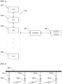
- FIG. 2 shows an example of an arrangement of the unattended ground sensors 100 in the train control system according to the present invention.
- the unattended ground sensors 100 i.e., the unattended ground sensor 100-1, the unattended ground sensor 100-2, the unattended ground sensor 100-3 and the unattended ground sensor 100-4 are shown for the sake of explanation. However, the number of the unattended ground sensors 100 is not limited thereto.
- the unattended ground sensor 100-1, the unattended ground sensor 100-2, the unattended ground sensor 100-3 and the unattended ground sensor 100-4 are respectively installed along a train line 400.
- the unattended ground sensor 100-1, the unattended ground sensor 100-2, the unattended ground sensor 100-3 and the unattended ground sensor 100-4 may be installed to be spaced apart from the train line 400 by predetermined intervals.
- the unattended ground sensor 100-1, the unattended ground sensor 100-2, the unattended ground sensor 100-3 and the unattended ground sensor 100-4 may be connected to the train line 400 through sensing lines 110-1 to 110-4, respectively.
- the unattended ground sensor 100-1, the unattended ground sensor 100-2, the unattended ground sensor 100-3 and the unattended ground sensor 100-4 may be connected to the train line 400 through the sensing lines 110-1 to 110-4, respectively.
- a positional distance between two adjacent unattended ground sensors, e.g., the unattended ground sensor 100-1 and the unattended ground sensor 100-2 among the plurality of unattended ground sensors 100 is determined based on the maximum sensing distance of each of the unattended ground sensors 100.
- the positional distance may be determined to be equal to or greater than 1/10 but equal to or less than 1/2 of the maximum sensing distance of each of the unattended ground sensor 100-1 and the unattended ground sensor 100-2.
- the positional distance between the unattended ground sensor 100-1 and the unattended ground sensor 100-2 is equal to or greater than 40 m but equal to or less than 200 m.
- the maximum sensing distance of each of the unattended ground sensors 100 is determined based on the case where the seismic waves generated from a large-size object such as a train are to be detected.
- the seismic waves can be normally detected by using the other one of the two unattended ground sensors.
- a position of a train is detected by using RFID tags
- the position of the train cannot be detected at a position where the RFID tag having the error is installed.
- the position of the train can be normally detected by using other unattended ground sensors.
- the unattended ground sensors 100 when a movement of a human being, instead of the large-size object such as the train, is to be detected by using the unattended ground sensors 100, a sensing distance of each of the unattended ground sensors 100 can be reduced.
- Each of the unattended ground sensors 100 is configured to detect the movement of the human being, e.g., within a range of 100 m therearound. Therefore, in the train control system according to the present invention, when the control device 200 performs a second control mode to be described later, the positional distance between the unattended ground sensor 100-1 and the unattended ground sensor 100-2 is set to be further reduced. In this case, the positional distance between the unattended ground sensor 100-1 and the unattended ground sensor 100-2 may be set to 50 m or more, and more preferably set to 40 m or more considering the difference in weight of a human being.
- the positional distance between the two adjacent unattended ground sensors 100-1 and 100-2 among the unattended ground sensors 100 is set to be equal to or greater than 1/10 but equal to or less than 1/2 of the maximum sensing distance of each of the unattended ground sensor 100-1 and the unattended ground sensor 100-2.
- the unattended ground sensor 100-1, the unattended ground sensor 100-2, the unattended ground sensor 100-3 and the unattended ground sensor 100-4 may communicate with one another through an ad-hoc wireless network.
- the unattended ground sensors 100 can be more efficiently and flexibly installed by allowing the unattended ground sensors 100 to communicate with one another through the ad-hoc wireless network without the aid of an access point (AP).
- AP access point
- the control device 200 is configured to at least perform a first control mode for detecting a position of the train based on the data transmitted from the unattended ground sensors.
- the control device 200 will be described in detail later.
- the gateway 300 is configured to enable communication between the unattended ground sensors 100 and the control device 200. For example, the gateway 300 receives data transmitted directly from each of the unattended ground sensors 100 or data transmitted from one or more of the unattended ground sensors 100 serving to collect data of other unattended ground sensors 100. Then, the gateway 300 transmits the received data to the control device 200.
- a plurality of the gateways 300 may be disposed. That is, the gateways 300 are disposed at different distances, and each of the gateways 300 preferably enables communication between the control device 200 and those of the unattended ground sensors 100 which are arranged within an area where the corresponding gateway is disposed.
- control device 200 is configured to at least perform the first control mode for detecting the position of the train based on the data transmitted from the unattended ground sensors 100.
- FIG. 3 shows an example in which the control device detects the position of the train based on the data transmitted from the unattended ground sensors in the train control system according to the present invention.
- FIG. 3 there is shown a configuration in which the position of the train is detected in real time by a first unattended ground sensor and a second unattended ground sensor while the train 500 is traveling on the train line 400.
- the first unattended ground sensor and the second unattended ground sensor are designated among the unattended ground sensors 100, and may be, e.g., the unattended ground sensor 100-1 and the unattended ground sensor 100-2 adjacent to each other or the unattended ground sensor 100-1 and the unattended ground sensor 100-3 that are not adjacent to each other.
- the first unattended ground sensor is the unattended ground sensor 100-1 and the second unattended ground sensor is the unattended ground sensor 100-2.
- the control device 200 is configured to perform the first control mode in which the position of the train is detected.
- a seismic wave is generated when the train 500 travels on the train line 400.
- the seismic wave is transmitted to each of the unattended ground sensors 100, i.e., each of the unattended ground sensor 100-1 and the unattended ground sensor 100-2 through the ground surface.
- a distance D between the unattended ground sensor 100-1 and the unattended ground sensor 100-2 is inputted in advance. Further, a propagation velocity v of the seismic wave is also inputted in advance. Since the propagation velocity v of the seismic wave may vary depending on the state of the medium between the unattended ground sensor 100-1 and the unattended ground sensor 100-2, it is preferable that the propagation velocity v is inputted in advance by obtaining it through the measurement.
- the control device 200 receives data from each of the unattended ground sensor 100-1 and the unattended ground sensor 100-2 and, based on the received data, calculates time T1 at which the seismic wave generated by the train 500 arrives at the unattended ground sensor 100-1 and time T2 at which the seismic wave generated by the train 500 arrives at the unattended ground sensor 100-2.
- the distance D1 between the train 500 and the unattended ground sensor 100-1 can be calculated on the basis of the distance D between the unattended ground sensor 100-1 and the unattended ground sensor 100-2; the propagation velocity v of the seismic wave; and the difference between the time T2 at which the seismic wave arrives at the unattended ground sensor 100-2 and the time T1 at which the seismic wave arrives at the unattended ground sensor 100-1.
- the unattended ground sensors 100-1 and 100-2 may be connected to the train line 400 through the sensing lines 110-1 and 110-2, respectively.
- the propagation velocity v of the seismic wave can be inputted in advance by obtaining it through the measurement using train line 400 as the medium.
- the distance D1 between the train 500 and the unattended ground sensor 100-1 can also be calculated on the basis of the distance D between the unattended ground sensor 100-1 and the unattended ground sensor 100-2; the propagation velocity v of the seismic wave; and the difference between the time T2 at which the seismic wave arrives at the unattended ground sensor 100-2 and the time T1 at which the seismic wave arrives at the unattended ground sensor 100-1.
- the control device 200 of the train control system according to the present invention may be configured to further perform other control modes as well as the first control mode for detecting the position of the train.
- FIG. 4 shows examples of control modes that can be performed by the control device of the train control system according to the present invention.
- control device 200 may be configured to perform the second control mode, a third control mode, a fourth control mode, and a fifth control mode in addition to the first control mode.
- the third control mode includes a first operation mode and a second operation mode.
- control device 200 may be configured to perform the second control mode in which safety information around the train line 400 is detected based on data transmitted from the unattended ground sensors 100.
- the risk of railway casualty accidents is high when an operator performs railway maintenance operation on the train line 400 or a person moves around the train line 400.
- the control device 200 detects vibrations around the train line 400 based on the data transmitted from the unattended ground sensors 100, and then detects the safety information based on the detected results. For example, in Fig. 3 , when the control device 200 receives data from each of the unattended ground sensor 100-1 and the unattended ground sensor 100-2, the position where the vibration has occurred can be detected as described with reference to Fig. 3 . Therefore, it is possible to easily detect a specific position around the train line 400 where the safety-related problem has currently occurred.
- the second control mode may be used to monitor the presence of an intruder around the train line 400. For example, after the train operation is stopped, the control device 200 performs the second control mode to detect the vibration in the vicinity of the train line 200. If the vibration is detected in the vicinity of the train line 200, there is a possibility that the safety-related problem has occurred. Therefore, the system manager is able to monitor the train line 200 based on the second control mode.
- an additional monitoring system for monitoring an intruder is required to be provided.
- the additional monitoring system since such vibration can be detected through the second control mode.
- the control device 200 is configured to perform the third control mode.
- the third control mode includes the first operation mode in which the first control mode and the second control mode are performed together and the second operation mode in which one of the first control mode and the second control mode is performed, and the control device 200 performs the third control mode by selecting one of the first operation mode and the second operation mode according to a predetermined criterion.
- the second control mode is performed together with the first control mode even while the train 500 is in operation.
- the safety information can also be detected by detecting another vibration around the train line 400.
- one of the first control mode and the second control mode is selected based on whether or not the train 500 is in operation, so that the first control mode is performed during which the train 500 is in operation and the second control mode is performed during which the train 500 is not in operation.
- control device 200 may be configured to perform the fourth control mode for dynamically selecting the first unattended ground sensor and the second unattended ground sensor based on the operating state of each of the unattended ground sensors 100.
- the unattended ground sensors 100 i.e., the unattended ground sensor 100-1, the unattended ground sensor 100-2, the unattended ground sensor 100-3 and the unattended ground sensor 100-4 are provided.
- the position of the train 200 may be detected by using the unattended ground sensor 100-1 as the first unattended ground sensor and the unattended ground sensor 100-2 as the second unattended ground sensor, respectively, as shown in FIG. 3 .
- the control device 100 may not normally receive data from the unattended ground sensor 100-2.
- control device 200 may detect the position of the train 500 by using other unattended ground sensors that are in normal operation.
- control device 200 may be configured to perform the fifth control mode for detecting a maintenance-required unattended ground sensor among the unattended ground sensors 100 based on the operating state of each of the unattended ground sensors 100.
- control device 200 receives data directly from each of the unattended ground sensors 100 or from some of the unattended ground sensors that collect the data from other unattended ground sensors 100, or the control device 200 receives data through the gateway 300.
- control device 200 may detect unattended ground sensors that are unable to generate data among the unattended ground sensors 100 and set such unattended ground sensor as the maintenance-required unattended ground sensors.
- the system manager may perform the maintenance operation for the detected unattended ground sensors through the fifth control mode.
- a train control system capable of efficiently and accurately detecting a position of a train by using a plurality of unattended ground sensors while minimizing a cost required for maintenance.
- the train control system capable of detecting an obstacle or the presence of a human being around a train line by using the plurality of unattended ground sensors installed to detect the position of the train, thereby preventing railway casualty accidents.
Landscapes
- Engineering & Computer Science (AREA)
- Mechanical Engineering (AREA)
- Automation & Control Theory (AREA)
- Physics & Mathematics (AREA)
- General Physics & Mathematics (AREA)
- Train Traffic Observation, Control, And Security (AREA)
- Geophysics And Detection Of Objects (AREA)
Claims (8)
- Zugsteuersystem, das Folgendes umfasst:eine Vielzahl von unbeaufsichtigten Bodensensoren (100), die entlang einer Zugstrecke (400) installiert sind; und eine Steuervorrichtung (200), die dazu ausgelegt ist, zum Durchführen von einem gemäß einem vorbestimmten Kriterium aus einem ersten Betriebsmodus und einem zweiten Betriebsmodus ausgewählten Betriebsmodus einen dritten Steuermodus durchzuführen,wobei im ersten Betriebsmodus zum Detektieren einer Position eines Zugs (500) auf Basis von Daten, die von den unbeaufsichtigten Bodensensoren (100) übertragen werden, wenn der Zug (500) auf der Zugstrecke (400) fährt, ein erster Steuermodus zusammen mit einem zweiten Steuermodus zum Detektieren von Sicherheitsinformationen um die Zugstrecke (400) auf Basis der Daten, die von den unbeaufsichtigten Bodensensoren (100) übertragen werden, wenn Vibrationen um die Zugstrecke (400) detektiert werden, durchgeführt wird und im zweiten Betriebsmodus entweder der erste Steuermodus oder der zweite Steuermodus durchgeführt wird.
- Zugsteuersystem nach Anspruch 1, wobei die Steuervorrichtung (200) eine aktuelle Position des Zugs (500) auf Basis einer Zeit, T1, zu der eine seismische Welle, die vom Zug (500) erzeugt wird, an einem ersten unbeaufsichtigten Bodensensor (100-1) der unbeaufsichtigten Bodensensoren (100) ankommt, einer Zeit, T2, zu der die seismische Welle an einem zweiten unbeaufsichtigten Bodensensor (100-2) der unbeaufsichtigten Bodensensoren (100) ankommt, einer Ausbreitungsgeschwindigkeit, v, der seismischen Welle und einem Abstand, D, zwischen dem ersten unbeaufsichtigten Bodensensor (100-1) und dem zweiten unbeaufsichtigten Bodensensor (100-2) detektiert.
- Zugsteuersystem nach Anspruch 1, wobei ein oder mehrere der unbeaufsichtigten Bodensensoren (100) über Erfassungsleitungen (110-1-110-4) mit der Zugstrecke (400) verbunden sind.
- Zugsteuersystem nach Anspruch 1, wobei ein Abstand zwischen zwei benachbarten unbeaufsichtigten Bodensensoren (100-1, 100-2) der unbeaufsichtigten Bodensensoren (100), die entlang der Zugstrecke (400) installiert sind, derart eingestellt ist, dass er gleich oder größer als 1/10, aber gleich oder kleiner als 1/2 eines maximalen Erfassungsabstandes von jedem der unbeaufsichtigten Bodensensoren ist.
- Zugsteuersystem nach Anspruch 2, wobei die Steuervorrichtung (200) ferner dazu ausgelegt ist, zum dynamischen Auswählen des ersten unbeaufsichtigten Bodensensors (100-1) und des zweiten unbeaufsichtigten Bodensensors (100-2) auf Basis eines Betriebszustands von jedem der unbeaufsichtigten Bodensensoren (100) einen vierten Steuermodus durchzuführen.
- Zugsteuersystem nach Anspruch 1, wobei die Steuervorrichtung (200) ferner dazu ausgelegt ist, zum Detektieren eines Wartungsbedarfs eines unbeaufsichtigten Bodensensors (100-1) unter den unbeaufsichtigten Bodensensoren (100) auf Basis eines Betriebszustands von jedem der unbeaufsichtigten Bodensensoren (100) einen fünften Steuermodus durchzuführen.
- Zugsteuersystem nach Anspruch 1, wobei die unbeaufsichtigten Bodensensoren (100) über ein drahtloses Ad-hoc-Netzwerk miteinander kommunizieren.
- Zugsteuersystem nach Anspruch 1, wobei das Zugsteuersystem ferner mindestens ein Gateway (300) umfasst, das dazu ausgelegt ist, eine Kommunikation zwischen den unbeaufsichtigten Bodensensoren (100) und der Steuervorrichtung (200) zu ermöglichen.
Applications Claiming Priority (2)
| Application Number | Priority Date | Filing Date | Title |
|---|---|---|---|
| KR1020160101087A KR101686458B1 (ko) | 2016-08-09 | 2016-08-09 | 열차 관제 시스템 |
| PCT/KR2017/007662 WO2018030660A1 (ko) | 2016-08-09 | 2017-07-17 | 열차 관제 시스템 |
Publications (4)
| Publication Number | Publication Date |
|---|---|
| EP3498569A1 EP3498569A1 (de) | 2019-06-19 |
| EP3498569A4 EP3498569A4 (de) | 2020-04-08 |
| EP3498569B1 true EP3498569B1 (de) | 2024-12-11 |
| EP3498569C0 EP3498569C0 (de) | 2024-12-11 |
Family
ID=57575362
Family Applications (1)
| Application Number | Title | Priority Date | Filing Date |
|---|---|---|---|
| EP17839678.4A Active EP3498569B1 (de) | 2016-08-09 | 2017-07-17 | Zugsteuerungssystem |
Country Status (3)
| Country | Link |
|---|---|
| EP (1) | EP3498569B1 (de) |
| KR (1) | KR101686458B1 (de) |
| WO (1) | WO2018030660A1 (de) |
Families Citing this family (1)
| Publication number | Priority date | Publication date | Assignee | Title |
|---|---|---|---|---|
| KR102167543B1 (ko) * | 2020-04-08 | 2020-10-19 | (주)케이디티콘트롤 | 지하철 관제 시스템의 병행 운전 절체기 |
Family Cites Families (10)
| Publication number | Priority date | Publication date | Assignee | Title |
|---|---|---|---|---|
| JPH06183346A (ja) * | 1992-12-21 | 1994-07-05 | Toei Denki Kogyo Kk | 列車接近検知方式及び列車接近検知装置 |
| JP2009132244A (ja) * | 2007-11-29 | 2009-06-18 | Akebono Brake Ind Co Ltd | 列車接近検知装置 |
| KR100998339B1 (ko) | 2009-06-30 | 2010-12-03 | (주)에이알텍 | 선로 감시 시스템 |
| KR20130001652A (ko) * | 2011-06-27 | 2013-01-04 | 엘에스산전 주식회사 | 무선열차검지유닛을 이용한 열차위치 검지 시스템 |
| JP5922954B2 (ja) * | 2012-03-06 | 2016-05-24 | 日本信号株式会社 | 列車検知装置 |
| KR101374350B1 (ko) | 2012-12-04 | 2014-03-19 | 한국철도기술연구원 | 열차 위치 검출 장치 |
| KR101458043B1 (ko) * | 2013-06-28 | 2014-11-04 | 한국철도기술연구원 | 열차 운행 환경 측정 장치 |
| KR101532960B1 (ko) * | 2013-11-01 | 2015-07-03 | 한국철도기술연구원 | 거리 센서를 이용한 열차 위치 검지 시스템 |
| US9919769B2 (en) | 2014-07-07 | 2018-03-20 | Anchor Bridle Pty Ltd | Device for interconnecting a first tether and a second tether |
| CA2870425C (en) * | 2014-11-12 | 2015-12-29 | Frank C. Van Der Merwe | Automated in motion railway seismic wheel failure detection system |
-
2016
- 2016-08-09 KR KR1020160101087A patent/KR101686458B1/ko active Active
-
2017
- 2017-07-17 EP EP17839678.4A patent/EP3498569B1/de active Active
- 2017-07-17 WO PCT/KR2017/007662 patent/WO2018030660A1/ko not_active Ceased
Also Published As
| Publication number | Publication date |
|---|---|
| KR101686458B1 (ko) | 2016-12-14 |
| WO2018030660A1 (ko) | 2018-02-15 |
| EP3498569A4 (de) | 2020-04-08 |
| EP3498569A1 (de) | 2019-06-19 |
| EP3498569C0 (de) | 2024-12-11 |
Similar Documents
| Publication | Publication Date | Title |
|---|---|---|
| US12214815B2 (en) | Method and monitoring system for determining a position of a rail vehicle | |
| EP2548784B1 (de) | Zugsteuersystem | |
| KR20160102533A (ko) | 위치 측정 방법, 자기 위치 측정 장치 및 차량 탑재 기기 | |
| US11325623B2 (en) | Rail breakage detection device and rail breakage detection system | |
| EP2614983A2 (de) | Zugsteuersystem | |
| EP3925853B1 (de) | System und verfahren zur erkennung von fehlerhaften standortdaten, die von einem zug gemeldet werden | |
| JP4945286B2 (ja) | 列車位置検知装置 | |
| EP2687419B1 (de) | Vorrichtung und Verfahren zur Überprüfung des Zustandes von Eisenbahngleisen | |
| PT2924662T (pt) | Onboard-unit e método para a vigilância de funcionamento num sistema rodoviário de portagens | |
| KR20180090745A (ko) | 열차 접근 경보 시스템 | |
| JP5225197B2 (ja) | 車両位置検知装置 | |
| US10101432B2 (en) | System and method for position and proximity detection | |
| KR20110101951A (ko) | 열차제어시스템 | |
| JP6494420B2 (ja) | 鉄道沿線監視システム、監視装置および鉄道沿線監視方法 | |
| EP3498569B1 (de) | Zugsteuerungssystem | |
| JP4912939B2 (ja) | 列車位置異常検知システム | |
| JPWO2018092307A1 (ja) | 通信制御装置、料金収受システム、通信制御方法及びプログラム | |
| KR100751057B1 (ko) | 무선통신을 이용한 열차 자동제어시스템 및 그 제어방법 | |
| KR101238702B1 (ko) | 디텍터를 이용한 철도건널목 지장물 검지장치 및 동 장치를 이용한 검지방법 | |
| US20240319380A1 (en) | Systems and methods for determining vehicle position | |
| JP2011124783A (ja) | 検知システム | |
| JPH1159419A (ja) | 列車接近警報装置 | |
| JP7300960B2 (ja) | センサ健全性確認システム及び鉄道車両 | |
| KR101855088B1 (ko) | 비콘을 활용한 gps 음영지역 해소 방법 및 시스템 | |
| JP2013130502A (ja) | 航法支援装置および航法装置 |
Legal Events
| Date | Code | Title | Description |
|---|---|---|---|
| STAA | Information on the status of an ep patent application or granted ep patent |
Free format text: STATUS: THE INTERNATIONAL PUBLICATION HAS BEEN MADE |
|
| PUAI | Public reference made under article 153(3) epc to a published international application that has entered the european phase |
Free format text: ORIGINAL CODE: 0009012 |
|
| STAA | Information on the status of an ep patent application or granted ep patent |
Free format text: STATUS: REQUEST FOR EXAMINATION WAS MADE |
|
| 17P | Request for examination filed |
Effective date: 20190206 |
|
| AK | Designated contracting states |
Kind code of ref document: A1 Designated state(s): AL AT BE BG CH CY CZ DE DK EE ES FI FR GB GR HR HU IE IS IT LI LT LU LV MC MK MT NL NO PL PT RO RS SE SI SK SM TR |
|
| AX | Request for extension of the european patent |
Extension state: BA ME |
|
| DAV | Request for validation of the european patent (deleted) | ||
| DAX | Request for extension of the european patent (deleted) | ||
| A4 | Supplementary search report drawn up and despatched |
Effective date: 20200305 |
|
| RIC1 | Information provided on ipc code assigned before grant |
Ipc: G01H 17/00 20060101ALI20200228BHEP Ipc: B61L 23/04 20060101ALI20200228BHEP Ipc: B61L 1/02 20060101ALI20200228BHEP Ipc: B61L 25/02 20060101AFI20200228BHEP Ipc: B61L 27/00 20060101ALI20200228BHEP |
|
| STAA | Information on the status of an ep patent application or granted ep patent |
Free format text: STATUS: EXAMINATION IS IN PROGRESS |
|
| 17Q | First examination report despatched |
Effective date: 20220421 |
|
| REG | Reference to a national code |
Ref country code: DE Ref legal event code: R079 Free format text: PREVIOUS MAIN CLASS: B61L0025020000 Ref country code: DE Ref legal event code: R079 Ref document number: 602017086740 Country of ref document: DE Free format text: PREVIOUS MAIN CLASS: B61L0025020000 Ipc: B61L0027200000 |
|
| RIC1 | Information provided on ipc code assigned before grant |
Ipc: B61L 1/02 20060101ALI20240617BHEP Ipc: G01H 17/00 20060101ALI20240617BHEP Ipc: B61L 23/04 20060101ALI20240617BHEP Ipc: B61L 25/02 20060101ALI20240617BHEP Ipc: B61L 27/00 20060101ALI20240617BHEP Ipc: B61L 27/20 20220101AFI20240617BHEP |
|
| GRAP | Despatch of communication of intention to grant a patent |
Free format text: ORIGINAL CODE: EPIDOSNIGR1 |
|
| STAA | Information on the status of an ep patent application or granted ep patent |
Free format text: STATUS: GRANT OF PATENT IS INTENDED |
|
| INTG | Intention to grant announced |
Effective date: 20240829 |
|
| GRAS | Grant fee paid |
Free format text: ORIGINAL CODE: EPIDOSNIGR3 |
|
| GRAA | (expected) grant |
Free format text: ORIGINAL CODE: 0009210 |
|
| STAA | Information on the status of an ep patent application or granted ep patent |
Free format text: STATUS: THE PATENT HAS BEEN GRANTED |
|
| RAP3 | Party data changed (applicant data changed or rights of an application transferred) |
Owner name: UNIONPLACE CO., LTD. |
|
| RIN1 | Information on inventor provided before grant (corrected) |
Inventor name: BANG, SEONGCHEOL Inventor name: JUN, JONGUK |
|
| AK | Designated contracting states |
Kind code of ref document: B1 Designated state(s): AL AT BE BG CH CY CZ DE DK EE ES FI FR GB GR HR HU IE IS IT LI LT LU LV MC MK MT NL NO PL PT RO RS SE SI SK SM TR |
|
| REG | Reference to a national code |
Ref country code: GB Ref legal event code: FG4D |
|
| REG | Reference to a national code |
Ref country code: CH Ref legal event code: EP |
|
| REG | Reference to a national code |
Ref country code: IE Ref legal event code: FG4D |
|
| REG | Reference to a national code |
Ref country code: DE Ref legal event code: R096 Ref document number: 602017086740 Country of ref document: DE |
|
| U01 | Request for unitary effect filed |
Effective date: 20250107 |
|
| U07 | Unitary effect registered |
Designated state(s): AT BE BG DE DK EE FI FR IT LT LU LV MT NL PT RO SE SI Effective date: 20250127 |
|
| PG25 | Lapsed in a contracting state [announced via postgrant information from national office to epo] |
Ref country code: HR Free format text: LAPSE BECAUSE OF FAILURE TO SUBMIT A TRANSLATION OF THE DESCRIPTION OR TO PAY THE FEE WITHIN THE PRESCRIBED TIME-LIMIT Effective date: 20241211 |
|
| PG25 | Lapsed in a contracting state [announced via postgrant information from national office to epo] |
Ref country code: ES Free format text: LAPSE BECAUSE OF FAILURE TO SUBMIT A TRANSLATION OF THE DESCRIPTION OR TO PAY THE FEE WITHIN THE PRESCRIBED TIME-LIMIT Effective date: 20241211 |
|
| PG25 | Lapsed in a contracting state [announced via postgrant information from national office to epo] |
Ref country code: NO Free format text: LAPSE BECAUSE OF FAILURE TO SUBMIT A TRANSLATION OF THE DESCRIPTION OR TO PAY THE FEE WITHIN THE PRESCRIBED TIME-LIMIT Effective date: 20250311 |
|
| PG25 | Lapsed in a contracting state [announced via postgrant information from national office to epo] |
Ref country code: GR Free format text: LAPSE BECAUSE OF FAILURE TO SUBMIT A TRANSLATION OF THE DESCRIPTION OR TO PAY THE FEE WITHIN THE PRESCRIBED TIME-LIMIT Effective date: 20250312 |
|
| PG25 | Lapsed in a contracting state [announced via postgrant information from national office to epo] |
Ref country code: RS Free format text: LAPSE BECAUSE OF FAILURE TO SUBMIT A TRANSLATION OF THE DESCRIPTION OR TO PAY THE FEE WITHIN THE PRESCRIBED TIME-LIMIT Effective date: 20250311 |
|
| PG25 | Lapsed in a contracting state [announced via postgrant information from national office to epo] |
Ref country code: SM Free format text: LAPSE BECAUSE OF FAILURE TO SUBMIT A TRANSLATION OF THE DESCRIPTION OR TO PAY THE FEE WITHIN THE PRESCRIBED TIME-LIMIT Effective date: 20241211 |
|
| PG25 | Lapsed in a contracting state [announced via postgrant information from national office to epo] |
Ref country code: PL Free format text: LAPSE BECAUSE OF FAILURE TO SUBMIT A TRANSLATION OF THE DESCRIPTION OR TO PAY THE FEE WITHIN THE PRESCRIBED TIME-LIMIT Effective date: 20241211 |
|
| PG25 | Lapsed in a contracting state [announced via postgrant information from national office to epo] |
Ref country code: IS Free format text: LAPSE BECAUSE OF FAILURE TO SUBMIT A TRANSLATION OF THE DESCRIPTION OR TO PAY THE FEE WITHIN THE PRESCRIBED TIME-LIMIT Effective date: 20250411 |
|
| PG25 | Lapsed in a contracting state [announced via postgrant information from national office to epo] |
Ref country code: SK Free format text: LAPSE BECAUSE OF FAILURE TO SUBMIT A TRANSLATION OF THE DESCRIPTION OR TO PAY THE FEE WITHIN THE PRESCRIBED TIME-LIMIT Effective date: 20241211 |
|
| PG25 | Lapsed in a contracting state [announced via postgrant information from national office to epo] |
Ref country code: CZ Free format text: LAPSE BECAUSE OF FAILURE TO SUBMIT A TRANSLATION OF THE DESCRIPTION OR TO PAY THE FEE WITHIN THE PRESCRIBED TIME-LIMIT Effective date: 20241211 |
|
| U20 | Renewal fee for the european patent with unitary effect paid |
Year of fee payment: 9 Effective date: 20250725 |
|
| PLBE | No opposition filed within time limit |
Free format text: ORIGINAL CODE: 0009261 |
|
| STAA | Information on the status of an ep patent application or granted ep patent |
Free format text: STATUS: NO OPPOSITION FILED WITHIN TIME LIMIT |
|
| REG | Reference to a national code |
Ref country code: CH Ref legal event code: L10 Free format text: ST27 STATUS EVENT CODE: U-0-0-L10-L00 (AS PROVIDED BY THE NATIONAL OFFICE) Effective date: 20251022 |
|
| 26N | No opposition filed |
Effective date: 20250912 |
|
| REG | Reference to a national code |
Ref country code: CH Ref legal event code: H13 Free format text: ST27 STATUS EVENT CODE: U-0-0-H10-H13 (AS PROVIDED BY THE NATIONAL OFFICE) Effective date: 20260224 |
|
| GBPC | Gb: european patent ceased through non-payment of renewal fee |
Effective date: 20250717 |
|
| PG25 | Lapsed in a contracting state [announced via postgrant information from national office to epo] |
Ref country code: GB Free format text: LAPSE BECAUSE OF NON-PAYMENT OF DUE FEES Effective date: 20250717 |