EP3498381A1 - Brenner - Google Patents
Brenner Download PDFInfo
- Publication number
- EP3498381A1 EP3498381A1 EP18212926.2A EP18212926A EP3498381A1 EP 3498381 A1 EP3498381 A1 EP 3498381A1 EP 18212926 A EP18212926 A EP 18212926A EP 3498381 A1 EP3498381 A1 EP 3498381A1
- Authority
- EP
- European Patent Office
- Prior art keywords
- burner
- spray
- medium
- burner head
- nozzle
- Prior art date
- Legal status (The legal status is an assumption and is not a legal conclusion. Google has not performed a legal analysis and makes no representation as to the accuracy of the status listed.)
- Ceased
Links
Images
Classifications
-
- F—MECHANICAL ENGINEERING; LIGHTING; HEATING; WEAPONS; BLASTING
- F23—COMBUSTION APPARATUS; COMBUSTION PROCESSES
- F23D—BURNERS
- F23D14/00—Burners for combustion of a gas, e.g. of a gas stored under pressure as a liquid
- F23D14/02—Premix gas burners, i.e. in which gaseous fuel is mixed with combustion air upstream of the combustion zone
-
- B—PERFORMING OPERATIONS; TRANSPORTING
- B05—SPRAYING OR ATOMISING IN GENERAL; APPLYING FLUENT MATERIALS TO SURFACES, IN GENERAL
- B05B—SPRAYING APPARATUS; ATOMISING APPARATUS; NOZZLES
- B05B1/00—Nozzles, spray heads or other outlets, with or without auxiliary devices such as valves, heating means
- B05B1/14—Nozzles, spray heads or other outlets, with or without auxiliary devices such as valves, heating means with multiple outlet openings; with strainers in or outside the outlet opening
- B05B1/20—Perforated pipes or troughs, e.g. spray booms; Outlet elements therefor
-
- F—MECHANICAL ENGINEERING; LIGHTING; HEATING; WEAPONS; BLASTING
- F23—COMBUSTION APPARATUS; COMBUSTION PROCESSES
- F23J—REMOVAL OR TREATMENT OF COMBUSTION PRODUCTS OR COMBUSTION RESIDUES; FLUES
- F23J7/00—Arrangement of devices for supplying chemicals to fire
-
- F—MECHANICAL ENGINEERING; LIGHTING; HEATING; WEAPONS; BLASTING
- F23—COMBUSTION APPARATUS; COMBUSTION PROCESSES
- F23L—SUPPLYING AIR OR NON-COMBUSTIBLE LIQUIDS OR GASES TO COMBUSTION APPARATUS IN GENERAL ; VALVES OR DAMPERS SPECIALLY ADAPTED FOR CONTROLLING AIR SUPPLY OR DRAUGHT IN COMBUSTION APPARATUS; INDUCING DRAUGHT IN COMBUSTION APPARATUS; TOPS FOR CHIMNEYS OR VENTILATING SHAFTS; TERMINALS FOR FLUES
- F23L7/00—Supplying non-combustible liquids or gases, other than air, to the fire, e.g. oxygen, steam
- F23L7/002—Supplying water
-
- B—PERFORMING OPERATIONS; TRANSPORTING
- B05—SPRAYING OR ATOMISING IN GENERAL; APPLYING FLUENT MATERIALS TO SURFACES, IN GENERAL
- B05B—SPRAYING APPARATUS; ATOMISING APPARATUS; NOZZLES
- B05B1/00—Nozzles, spray heads or other outlets, with or without auxiliary devices such as valves, heating means
- B05B1/14—Nozzles, spray heads or other outlets, with or without auxiliary devices such as valves, heating means with multiple outlet openings; with strainers in or outside the outlet opening
- B05B1/20—Perforated pipes or troughs, e.g. spray booms; Outlet elements therefor
- B05B1/205—Perforated pipes or troughs, e.g. spray booms; Outlet elements therefor characterised by the longitudinal shape of the elongated body
- B05B1/207—Perforated pipes or troughs, e.g. spray booms; Outlet elements therefor characterised by the longitudinal shape of the elongated body the elongated body being a closed loop
-
- F—MECHANICAL ENGINEERING; LIGHTING; HEATING; WEAPONS; BLASTING
- F23—COMBUSTION APPARATUS; COMBUSTION PROCESSES
- F23D—BURNERS
- F23D2900/00—Special features of, or arrangements for burners using fluid fuels or solid fuels suspended in a carrier gas
- F23D2900/00016—Preventing or reducing deposit build-up on burner parts, e.g. from carbon
-
- F—MECHANICAL ENGINEERING; LIGHTING; HEATING; WEAPONS; BLASTING
- F23—COMBUSTION APPARATUS; COMBUSTION PROCESSES
- F23J—REMOVAL OR TREATMENT OF COMBUSTION PRODUCTS OR COMBUSTION RESIDUES; FLUES
- F23J2215/00—Preventing emissions
- F23J2215/10—Nitrogen; Compounds thereof
- F23J2215/101—Nitrous oxide (N2O)
Definitions
- the invention relates to a burner for generating a burner flame for heating or melting a good, such as scrap, ore or slag, z. B. in a metallurgical vessel.
- Such burners are basically known in the art, for. B. from the German patent application DE 10 2015 220 305 A1 ,
- the known burners have the disadvantage that they offer no protection against caking on the burner head.
- they offer no possibility for supplying liquid or gaseous catalysts to reduce emissions and to influence the thermochemical reactions in the area of the burner flame or the combustion zone.
- the invention is therefore the object of developing a known burner to the effect that it is protected from caking and / or offers the possibility of feeding catalysts into the combustion zone.
- the burner according to the invention is characterized by a third supply line for a spray medium and a fluidically connected to the third supply line and arranged on the burner head spray nozzle with at least one nozzle opening for atomizing the supplied spray medium to a spray and for dispensing the spray in the burner head and / or burner flame.
- the spray medium used may be liquid or gaseous. Especially in the use of liquid spray medium speaks the present Description of spray mist. When using a gaseous spray medium typically produces a spray fog. In the context of the present description, however, for the sake of simplicity, only spray mist is discussed.
- spray therefore also includes the term “spray fog”, ie the use of gaseous spray media.
- the claimed spray nozzle has the advantage that it allows a supply of the spray medium in the atomized state in the region of the burner head and / or in the region of the burner flame or the combustion zone. This offers the advantage that caking on the burner head can be prevented. Alternatively or simultaneously, the atomized spray medium in the combustion zone acts as a catalyst for the thermochemical reactions taking place there.
- the prerequisite is that the spray medium is supplied in the correct composition and in the correct amount.
- Sprühmedium own z.
- liquid NUx reducing agents such as selective non-catalytic reduction (SNCR), or water or reaction gases such as carbon monoxide.
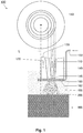
- FIG. 1 shows the burner according to the invention in particular in a cross-sectional view and in a radial sectional view.
- FIG. 1 shows the burner 100 according to the invention.
- the concentric circles in the upper part of FIG. 1 show a cross section through the burner 100, in particular by its rotationally symmetrical burner head 140.
- a first feeder 110 for an energy carrier medium and a second feeder 120 for an oxidation medium are arranged on the longitudinal axis L of the burner head.
- FIG. 3 shows a longitudinal section through the burner head 140, again with the first feed 110 and the second feed 120.
- the adjusting devices 130 are located in the FIG. 1 shown embodiment in the direction of the longitudinal axis L, see the two double arrows, relative to each other displaceable, whereby the cross sections of the first and second feed are individually adjustable.
- the energy carrier medium and / or the oxidation medium can be metered individually.
- the in FIG. 1 shown adjusting means 130 shown only by way of example; the object of the invention is not contrary, if any other adjustment or no adjustment for the energy carrier medium and / or the oxidation medium are provided.
- the special feature of the present invention is to be recognized, namely a spray nozzle 160 arranged at the burner head with at least one nozzle opening 162 for atomizing a spray medium supplied via a third feed line 150 into a spray 400.
- the spray nozzle 160 is formed in the form of a spray ring extending around the outlet opening 145 of the burner head 140 with a plurality of nozzle openings 162.
- the nozzle openings 162 are preferably aligned such that the spray mist is directed in the exit direction R of the nozzle Burner flame and / or sprayed with a radial component to the outlet direction R radially outward. Irrespective of the direction of exit of the nozzle openings 162, however, the mist has the property of spreading in an undirected manner in the region of the burner head and / or in the region of the burner flame or in the combustion zone defined by the burner flame.
- This third supply line 150 may be in the form of a channel in the interior of the burner 100 or, in particular, in the interior of the burner head 140. Alternatively, it may also be designed in the form of a line outside the burner head and guided to the nozzle 160.
- the spray forms in the area of the burner flame or the combustion zone it acts there - depending on the nature of its chemical composition - as a catalyst for the reduction of immissions or generally for influencing the thermochemical reactions taking place there.
- the burner flame 200 impinges on a to be heated or melted Good 300.
Landscapes
- Engineering & Computer Science (AREA)
- Mechanical Engineering (AREA)
- General Engineering & Computer Science (AREA)
- Chemical & Material Sciences (AREA)
- Combustion & Propulsion (AREA)
Abstract
Description
- Die Erfindung betrifft einen Brenner zum Erzeugen einer Brennerflamme zum Aufheizen oder Schmelzen eines Gutes, beispielsweise Schrott, Erz oder Schlacke, z. B. in einem metallurgischen Gefäß.
- Derartige Brenner sind im Stand der Technik grundsätzlich bekannt, z. B. aus der deutschen Offenlegungsschrift
DE 10 2015 220 305 A1 . Die bekannten Brenner haben jedoch den Nachteil, dass sie keinen Schutz vor Anbackungen am Brennerkopf bieten. Außerdem bieten sie keine Möglichkeit zum Zuführen von flüssigen oder gasförmigen Katalysatoren zur Reduktion von Emissionen und zur Beeinflussung der thermochemischen Reaktionen im Bereich der Brennerflamme bzw. der Verbrennungszone. - Der Erfindung liegt deshalb die Aufgabe zugrunde, einen bekannten Brenner dahingehend weiterzubilden, dass er vor Anbackungen geschützt wird und/oder die Möglichkeit zum Zuführen von Katalysatoren in die Verbrennungszone bietet.
- Diese Aufgabe wird durch den Gegenstand des Patentanspruchs 1 gelöst. Der erfindungsgemäße Brenner ist gekennzeichnet durch eine dritte Zuleitung für ein Sprühmedium und eine mit der dritten Zuleitung fluidleitend verbundene und am Brennerkopf angeordnete Sprühdüse mit mindestens einer Düsenöffnung zum Zerstäuben des zugeführten Sprühmediums zu einem Sprühnebel und zum Ausgeben des Sprühnebels im Bereich des Brennerkopfes und/oder der Brennerflamme.
- Das verwendete Sprühmedium kann flüssig oder gasförmig sein. Insbesondere bei der Verwendung von flüssigem Sprühmedium spricht die vorliegende Beschreibung von Sprühnebel. Bei Verwendung eines gasförmigen Sprühmediums entsteht typischerweise ein Sprühschleier. Im Rahmen der vorliegenden Beschreibung wird jedoch vereinfachend nur von Sprühnebel gesprochen. Der Begriff "Sprühnebel" schließt deshalb auch den Begriff "Sprühschleier", d. h. die Verwendung von gasförmigen Sprühmedien mit ein.
- Die beanspruchte Sprühdüse bietet den Vorteil, dass sie eine Zuführung des Sprühmediums im zerstäubten Zustand in den Bereich des Brennerkopfes und/oder in den Bereich der Brennerflamme bzw. der Verbrennungszone ermöglicht. Dies bietet den Vorteil, dass Anbackungen am Brennerkopf verhindert werden. Alternativ oder gleichzeitig wirkt das zerstäubte Sprühmedium in der Verbrennungszone als Katalysator für die dort stattfindenden thermochemischen Reaktionen.
- Voraussetzung ist, dass das Sprühmedium in der richtigen Zusammensetzung und in der richtigen Menge zugeführt wird. Als Sprühmedium eigenen sich z. B. flüssige NUx-Reduktionsmittel, wie beispielsweise Selectiv-Non-Catalytic Reduction (SNCR), oder Wasser oder Reaktionsgase wie beispielsweise Kohlenmonoxyd.
- Besondere Ausgestaltungen des erfindungsgemäßen Brenners sind Gegenstand der abhängigen Ansprüche.
- Der Beschreibung ist eine
Figur 1 beigefügt, welche den erfindungsgemäßen Brenner insbesondere in einer Querschnittsansicht und in einer radialen Schnittdarstellung zeigt. - Die Erfindung wird nachfolgend unter Bezugnahme auf diese
Figur 1 in Form von Ausführungsbeispielen näher beschrieben. -
Figur 1 zeigt den erfindungsgemäßen Brenner 100. Die konzentrischen Kreise im oberen Teil derFigur 1 zeigen einen Querschnitt durch den Brenner 100, insbesondere durch dessen rotationssymmetrischen Brennerkopf 140. Zu erkennen ist, dass im Inneren des Brennerkopfes eine erste Zuführung 110 für ein Energieträger-Medium und eine zweite Zuführung 120 für ein Oxidationsmedium, vorzugsweise jeweils koaxial zueinander und koaxial in Bezug auf die Längsachse L des Brennerkopfes angeordnet sind. - Im mittleren Teil der
Figur 1 ist ein Längsschnitt durch den Brennerkopf 140 gezeigt, wiederum mit der ersten Zuführung 110 und der zweiten Zuführung 120. Diese beiden Zuführungen werden begrenzt bzw. aufgespannt insbesondere durch Verstelleinrichtungen 130 und den Brennerkopf 140. Die Verstelleinrichtungen 130 sind in dem inFigur 1 gezeigten Ausführungsbeispiel in Richtung der Längsachse L, siehe die beiden Doppelpfeile, relativ zueinander verschiebbar, wodurch die Querschnitte der ersten und der zweiten Zuführung individuell einstellbar sind. Dadurch lassen sich das Energieträger-Medium und/oder das Oxidationsmedium individuell dosieren. Selbstverständlich sind die inFigur 1 gezeigten Verstelleinrichtungen 130 lediglich beispielhaft gezeigt; dem Gegenstand der Erfindung steht es nicht entgegen, wenn auch beliebige andere Verstelleinrichtungen oder gar keine Verstelleinrichtungen für das Energieträger-Medium und/oder das Oxidationsmedium vorgesehen sind. - In
Figur 1 ist weiterhin das besondere Merkmal der vorliegenden Erfindung zu erkennen, nämlich eine am Brennerkopf angeordnete Sprühdüse 160 mit mindestens einer Düsenöffnung 162 zum Zerstäuben eines über eine dritte Zuleitung 150 zugeführten Sprühmediums zu einem Sprühnebel 400. - Vorteilhafterweise ist die Sprühdüse 160 ausgebildet in Form eines um die Auslassöffnung 145 des Brennerkopfes 140 herum verlaufenden Sprührings mit einer Mehrzahl von Düsenöffnungen 162. Die Düsenöffnungen 162 sind vorzugsweise so ausgerichtet, dass der Sprühnebel in die Austrittsrichtung R der Brennerflamme und/oder mit einer radialen Komponente zu der Austrittsrichtung R nach radial Außen gesprüht wird. Ungeachtet von der Austrittsrichtung der Düsenöffnungen 162 hat der Nebel jedoch die Eigenschaft, sich ungerichtet im Bereich des Brennerkopfes und/oder im Bereich der Brennerflamme bzw. in der durch die Brennerflamme definierten Verbrennungszone gasförmig auszubreiten.
- Die Zuführung des Sprühmediums zu der Düse bzw. dem Sprühring 160 erfolgt über eine dritte separate Zuleitung 150 speziell für das Sprühmedium. Diese dritte Zuleitung 150 kann in Form eines Kanals im Inneren des Brenners 100 bzw. insbesondere im Inneren des Brennerkopfes 140 ausgebildet sein. Alternativ kann sie auch in Form einer Leitung außerhalb des Brennerkopfes ausgebildet und zu der Düse 160 geführt sein.
- Soweit sich der Nebel im Bereich des Brennerkopfes 140 ausbreitet und diesen umgibt bzw. umnebelt, verhindert er dort die Ausbildung von Anbackungen. Soweit sich der Sprühnebel im Bereich der Brennerflamme bzw. der Verbrennungszone ausbildet, fungiert er dort - je nach Art seiner chemischen Zusammensetzung - als Katalysator zur Reduktion von Immissionen oder allgemein zur Beeinflussung der dort stattfindenden thermochemischen Reaktionen. Im unteren Teil der
Figur 1 ist gezeigt, dass die Brennerflamme 200 auf ein aufzuheizendes oder aufzuschmelzendes Gut 300 auftrifft. -
- 100
- Brenner
- 110
- erste Zuführung für Energieträger-Medium
- 120
- zweite Zuführung für Oxidationsmedium
- 140
- Brennerkopf
- 145
- Auslassöffnung am Brennerkopf
- 150
- dritte Zuleitung für ein Sprühmedium
- 160
- Sprühdüse
- 162
- Düsenöffnung
- 200
- Brennerflamme
- 300
- aufzuheizendes bzw. einzuschmelzendes Gut, insbesondere Schrottschüttung
- 400
- Sprühnebel
- R
- Austrittsrichtung des Energiemediums und des Oxidationsmediums aus dem Brennerkopf
- L
- Längsachse des Brennerkopfes
Claims (4)
- Brenner (100) aufweisend:eine erste Zuführung (110) für ein Energieträger-Medium und eine zweite Zuführung (120) für ein Oxidationsmedium; undeinen Brennerkopf (140) mit einer Auslassöffnung (145) zum Austragen des Energiemediums und des Oxidationsmediums, vorzugsweise miteinander vermischt, in einer Austrittsrichtung (R) zum Erzeugen einer Brennerflamme (200) ;gekennzeichnet durcheine dritte Zuleitung (150) für ein Sprühmedium; undeine mit der dritten Zuleitung fluidleitend verbundene und am Brennerkopf angeordnete Sprühdüse (160) mit mindestens einer Düsenöffnung (162) zum Zerstäuben des zugeführten Sprühmediums zu einem Sprühnebel und zum Ausgeben des Sprühnebels (400) im Bereich des Brennerkopfes (140) und/oder der Brennerflamme (200).
- Brenner (100) nach Anspruch 1;
dadurch gekennzeichnet,
dass die Sprühdüse (160) ausgebildet ist in Form eines um die Auslassöffnung (145) des Brennerkopfes (140) herum verlaufenden Sprührings mit einer Mehrzahl von Düsenöffnungen (162) zum Ausgeben des Sprühnebels, vorzugsweise über den Umfang des Brennerkopfes verteilt. - Brenner (100) nach einem der vorangegangenen Ansprüche,
dadurch gekennzeichnet,
dass die dritte Zuleitung (150) für das Sprühmedium in Form eines Kanals im Innern des Brenners oder in Form einer Leitung außerhalb des Brenners ausgebildet und zu der Düse geführt ist. - Brenner nach einem der vorangegangenen Ansprüche,
dadurch gekennzeichnet,
dass Verstelleinrichtungen (130) vorgesehen sind zum individuellen Dosieren des Energieträger-Mediums und/oder des Oxidationsmediums.
Applications Claiming Priority (1)
| Application Number | Priority Date | Filing Date | Title |
|---|---|---|---|
| DE102017223113.0A DE102017223113A1 (de) | 2017-12-18 | 2017-12-18 | Brenner |
Publications (1)
| Publication Number | Publication Date |
|---|---|
| EP3498381A1 true EP3498381A1 (de) | 2019-06-19 |
Family
ID=64744370
Family Applications (1)
| Application Number | Title | Priority Date | Filing Date |
|---|---|---|---|
| EP18212926.2A Ceased EP3498381A1 (de) | 2017-12-18 | 2018-12-17 | Brenner |
Country Status (2)
| Country | Link |
|---|---|
| EP (1) | EP3498381A1 (de) |
| DE (1) | DE102017223113A1 (de) |
Citations (4)
| Publication number | Priority date | Publication date | Assignee | Title |
|---|---|---|---|---|
| US4785748A (en) * | 1987-08-24 | 1988-11-22 | The Marquardt Company | Method sudden expansion (SUE) incinerator for destroying hazardous materials & wastes |
| US5199255A (en) * | 1991-04-03 | 1993-04-06 | Nalco Fuel Tech | Selective gas-phase nox reduction in gas turbines |
| US6234092B1 (en) * | 1998-12-16 | 2001-05-22 | Basf Aktiengesellschaft | Thermal treatment of incombustible liquids |
| US20140209310A1 (en) * | 2010-03-08 | 2014-07-31 | World Energy Systems Incorporated | Downhole steam generator and method of use |
Family Cites Families (6)
| Publication number | Priority date | Publication date | Assignee | Title |
|---|---|---|---|---|
| DE3121370A1 (de) * | 1981-05-29 | 1983-05-19 | Korel Korrosionsschutz-Elektronik Gmbh & Co Kg, 4030 Ratingen | Pressluft-gasbrenner zum betrieb von flammspritzpistolen und als trockner |
| CZ282294A3 (en) * | 1990-06-29 | 1997-07-16 | Babcock Hitachi Kk | Burner for combustion conjointly gaseous and pulverulent fuels |
| US5129818A (en) * | 1990-09-14 | 1992-07-14 | Benno Balsiger | Method of feeding back exhaust gases in oil and gas burners |
| US5525053A (en) * | 1994-12-01 | 1996-06-11 | Wartsila Diesel, Inc. | Method of operating a combined cycle power plant |
| ITMI991204A1 (it) * | 1999-05-31 | 2000-12-01 | Nuovo Pignone Spa | Iniettore di combustibile liquido per bruciatori in turbine a gas |
| DE102015220305A1 (de) | 2015-10-19 | 2017-04-20 | Sms Group Gmbh | Brenner |
-
2017
- 2017-12-18 DE DE102017223113.0A patent/DE102017223113A1/de not_active Withdrawn
-
2018
- 2018-12-17 EP EP18212926.2A patent/EP3498381A1/de not_active Ceased
Patent Citations (4)
| Publication number | Priority date | Publication date | Assignee | Title |
|---|---|---|---|---|
| US4785748A (en) * | 1987-08-24 | 1988-11-22 | The Marquardt Company | Method sudden expansion (SUE) incinerator for destroying hazardous materials & wastes |
| US5199255A (en) * | 1991-04-03 | 1993-04-06 | Nalco Fuel Tech | Selective gas-phase nox reduction in gas turbines |
| US6234092B1 (en) * | 1998-12-16 | 2001-05-22 | Basf Aktiengesellschaft | Thermal treatment of incombustible liquids |
| US20140209310A1 (en) * | 2010-03-08 | 2014-07-31 | World Energy Systems Incorporated | Downhole steam generator and method of use |
Also Published As
| Publication number | Publication date |
|---|---|
| DE102017223113A1 (de) | 2019-06-19 |
Similar Documents
| Publication | Publication Date | Title |
|---|---|---|
| EP0902233B1 (de) | Kombinierte Druckzerstäuberdüse | |
| DE3933050A1 (de) | Verfahren zum betreiben eines brenners fuer drehrohroefen und brenner hierfuer | |
| DE69409075T2 (de) | Vorrichtung und Verfahren zur Verbrennung | |
| DE1551638A1 (de) | Brenner | |
| DE1906895A1 (de) | Verfahren und Vorrichtung zur direkten Heizung von Wirbelschichtreaktoren | |
| DE2659170A1 (de) | Verfahren und brenner zur teilverbrennung eines fluessigen oder gasfoermigen brennstoffes | |
| DE3006558C2 (de) | ||
| DE4239903C1 (de) | Injektor-Mundstück für Brenneraggregate | |
| DE2204715A1 (de) | Verfahren und vorrichtung zum abkuehlen der flamme eines industrie-gasbrenners | |
| EP0057747A2 (de) | Brenner für die Verbrennung staubförmiger Brennstoffe | |
| DE102017223113A1 (de) | Brenner | |
| AT504732B1 (de) | Brenner | |
| EP0458018A2 (de) | Verfahren und Vorrichtung zum Hochgeschwindigkeitsflammspritzen von hochschmelzenden draht- und pulverförmigen Zusatzwerkstoffen zum Beschichten von Oberflächen | |
| DE2309821C2 (de) | Verfahren und Brenner zur Herstellung einer hauptsächlich Wasserstoff und Kohlenmonoxid enthaltenden Gasmischung | |
| DE1937254B2 (de) | Zerstaeubungsbrenner fuer fluessigen brennstoff | |
| DE2138746A1 (de) | Brenner für flüssigen Brennstoff | |
| DE2150112C3 (de) | Brenner mit Brennkammer und koaxial in der Oxidationsmittelzufuhrleitung gehaltertem Brennstoffverteilerrohr | |
| DE10224350B3 (de) | Zerstäuberbrenner mit einem Venturirohr für ein Heizgerät | |
| DE4007080C2 (de) | Vorrichtung zum Einbringen und Zerstäuben von förderbaren Medien, insbesondere in Feuerungsräume | |
| DE2819146C2 (de) | Vorrichtung zum Markieren von Werkstucken mittels Pulver | |
| DE4229525A1 (de) | Mischeinrichtung für Ölzerstäubungsbrenner | |
| DE2715456A1 (de) | Mischkopf fuer brenner kleiner heizleistungen | |
| DE3824887C2 (de) | ||
| DE2743567A1 (de) | Brennerduese fuer flammspritzgeraete | |
| DE371456C (de) | Verfahren und Vorrichtung zum Emaillieren, Verglasen und Verquarzen sowie zum Aufschweissen von pulverfoermigen Hartmetallen |
Legal Events
| Date | Code | Title | Description |
|---|---|---|---|
| PUAI | Public reference made under article 153(3) epc to a published international application that has entered the european phase |
Free format text: ORIGINAL CODE: 0009012 |
|
| 17P | Request for examination filed |
Effective date: 20181217 |
|
| AK | Designated contracting states |
Kind code of ref document: A1 Designated state(s): AL AT BE BG CH CY CZ DE DK EE ES FI FR GB GR HR HU IE IS IT LI LT LU LV MC MK MT NL NO PL PT RO RS SE SI SK SM TR |
|
| AX | Request for extension of the european patent |
Extension state: BA ME |
|
| RBV | Designated contracting states (corrected) |
Designated state(s): AL AT BE BG CH CY CZ DE DK EE ES FI FR GB GR HR HU IE IS IT LI LT LU LV MC MK MT NL NO PL PT RO RS SE SI SK SM TR |
|
| STAA | Information on the status of an ep patent application or granted ep patent |
Free format text: STATUS: THE APPLICATION HAS BEEN REFUSED |
|
| 18R | Application refused |
Effective date: 20191124 |