EP3498375B1 - Fluidverarbeitung und -steuerung - Google Patents
Fluidverarbeitung und -steuerung Download PDFInfo
- Publication number
- EP3498375B1 EP3498375B1 EP19156251.1A EP19156251A EP3498375B1 EP 3498375 B1 EP3498375 B1 EP 3498375B1 EP 19156251 A EP19156251 A EP 19156251A EP 3498375 B1 EP3498375 B1 EP 3498375B1
- Authority
- EP
- European Patent Office
- Prior art keywords
- fluid
- processing
- chambers
- region
- chamber
- Prior art date
- Legal status (The legal status is an assumption and is not a legal conclusion. Google has not performed a legal analysis and makes no representation as to the accuracy of the status listed.)
- Expired - Lifetime
Links
Images














Classifications
-
- B—PERFORMING OPERATIONS; TRANSPORTING
- B01—PHYSICAL OR CHEMICAL PROCESSES OR APPARATUS IN GENERAL
- B01L—CHEMICAL OR PHYSICAL LABORATORY APPARATUS FOR GENERAL USE
- B01L3/00—Containers or dishes for laboratory use, e.g. laboratory glassware; Droppers
- B01L3/50—Containers for the purpose of retaining a material to be analysed, e.g. test tubes
- B01L3/502—Containers for the purpose of retaining a material to be analysed, e.g. test tubes with fluid transport, e.g. in multi-compartment structures
-
- B—PERFORMING OPERATIONS; TRANSPORTING
- B01—PHYSICAL OR CHEMICAL PROCESSES OR APPARATUS IN GENERAL
- B01L—CHEMICAL OR PHYSICAL LABORATORY APPARATUS FOR GENERAL USE
- B01L3/00—Containers or dishes for laboratory use, e.g. laboratory glassware; Droppers
- B01L3/50—Containers for the purpose of retaining a material to be analysed, e.g. test tubes
- B01L3/502—Containers for the purpose of retaining a material to be analysed, e.g. test tubes with fluid transport, e.g. in multi-compartment structures
- B01L3/5027—Containers for the purpose of retaining a material to be analysed, e.g. test tubes with fluid transport, e.g. in multi-compartment structures by integrated microfluidic structures, i.e. dimensions of channels and chambers are such that surface tension forces are important, e.g. lab-on-a-chip
- B01L3/502715—Containers for the purpose of retaining a material to be analysed, e.g. test tubes with fluid transport, e.g. in multi-compartment structures by integrated microfluidic structures, i.e. dimensions of channels and chambers are such that surface tension forces are important, e.g. lab-on-a-chip characterised by interfacing components, e.g. fluidic, electrical, optical or mechanical interfaces
-
- B—PERFORMING OPERATIONS; TRANSPORTING
- B01—PHYSICAL OR CHEMICAL PROCESSES OR APPARATUS IN GENERAL
- B01L—CHEMICAL OR PHYSICAL LABORATORY APPARATUS FOR GENERAL USE
- B01L3/00—Containers or dishes for laboratory use, e.g. laboratory glassware; Droppers
- B01L3/50—Containers for the purpose of retaining a material to be analysed, e.g. test tubes
- B01L3/502—Containers for the purpose of retaining a material to be analysed, e.g. test tubes with fluid transport, e.g. in multi-compartment structures
- B01L3/5027—Containers for the purpose of retaining a material to be analysed, e.g. test tubes with fluid transport, e.g. in multi-compartment structures by integrated microfluidic structures, i.e. dimensions of channels and chambers are such that surface tension forces are important, e.g. lab-on-a-chip
- B01L3/50273—Containers for the purpose of retaining a material to be analysed, e.g. test tubes with fluid transport, e.g. in multi-compartment structures by integrated microfluidic structures, i.e. dimensions of channels and chambers are such that surface tension forces are important, e.g. lab-on-a-chip characterised by the means or forces applied to move the fluids
-
- B—PERFORMING OPERATIONS; TRANSPORTING
- B01—PHYSICAL OR CHEMICAL PROCESSES OR APPARATUS IN GENERAL
- B01L—CHEMICAL OR PHYSICAL LABORATORY APPARATUS FOR GENERAL USE
- B01L3/00—Containers or dishes for laboratory use, e.g. laboratory glassware; Droppers
- B01L3/50—Containers for the purpose of retaining a material to be analysed, e.g. test tubes
- B01L3/502—Containers for the purpose of retaining a material to be analysed, e.g. test tubes with fluid transport, e.g. in multi-compartment structures
- B01L3/5027—Containers for the purpose of retaining a material to be analysed, e.g. test tubes with fluid transport, e.g. in multi-compartment structures by integrated microfluidic structures, i.e. dimensions of channels and chambers are such that surface tension forces are important, e.g. lab-on-a-chip
- B01L3/502738—Containers for the purpose of retaining a material to be analysed, e.g. test tubes with fluid transport, e.g. in multi-compartment structures by integrated microfluidic structures, i.e. dimensions of channels and chambers are such that surface tension forces are important, e.g. lab-on-a-chip characterised by integrated valves
-
- G—PHYSICS
- G01—MEASURING; TESTING
- G01N—INVESTIGATING OR ANALYSING MATERIALS BY DETERMINING THEIR CHEMICAL OR PHYSICAL PROPERTIES
- G01N1/00—Sampling; Preparing specimens for investigation
- G01N1/02—Devices for withdrawing samples
- G01N1/10—Devices for withdrawing samples in the liquid or fluent state
- G01N1/18—Devices for withdrawing samples in the liquid or fluent state with provision for splitting samples into portions
-
- G—PHYSICS
- G01—MEASURING; TESTING
- G01N—INVESTIGATING OR ANALYSING MATERIALS BY DETERMINING THEIR CHEMICAL OR PHYSICAL PROPERTIES
- G01N1/00—Sampling; Preparing specimens for investigation
- G01N1/28—Preparing specimens for investigation including physical details of (bio-)chemical methods covered elsewhere, e.g. G01N33/50, C12Q
-
- G—PHYSICS
- G01—MEASURING; TESTING
- G01N—INVESTIGATING OR ANALYSING MATERIALS BY DETERMINING THEIR CHEMICAL OR PHYSICAL PROPERTIES
- G01N1/00—Sampling; Preparing specimens for investigation
- G01N1/28—Preparing specimens for investigation including physical details of (bio-)chemical methods covered elsewhere, e.g. G01N33/50, C12Q
- G01N1/40—Concentrating samples
- G01N1/405—Concentrating samples by adsorption or absorption
-
- B—PERFORMING OPERATIONS; TRANSPORTING
- B01—PHYSICAL OR CHEMICAL PROCESSES OR APPARATUS IN GENERAL
- B01L—CHEMICAL OR PHYSICAL LABORATORY APPARATUS FOR GENERAL USE
- B01L2200/00—Solutions for specific problems relating to chemical or physical laboratory apparatus
- B01L2200/06—Fluid handling related problems
-
- B—PERFORMING OPERATIONS; TRANSPORTING
- B01—PHYSICAL OR CHEMICAL PROCESSES OR APPARATUS IN GENERAL
- B01L—CHEMICAL OR PHYSICAL LABORATORY APPARATUS FOR GENERAL USE
- B01L2200/00—Solutions for specific problems relating to chemical or physical laboratory apparatus
- B01L2200/10—Integrating sample preparation and analysis in single entity, e.g. lab-on-a-chip concept
-
- B—PERFORMING OPERATIONS; TRANSPORTING
- B01—PHYSICAL OR CHEMICAL PROCESSES OR APPARATUS IN GENERAL
- B01L—CHEMICAL OR PHYSICAL LABORATORY APPARATUS FOR GENERAL USE
- B01L2200/00—Solutions for specific problems relating to chemical or physical laboratory apparatus
- B01L2200/16—Reagents, handling or storing thereof
-
- B—PERFORMING OPERATIONS; TRANSPORTING
- B01—PHYSICAL OR CHEMICAL PROCESSES OR APPARATUS IN GENERAL
- B01L—CHEMICAL OR PHYSICAL LABORATORY APPARATUS FOR GENERAL USE
- B01L2300/00—Additional constructional details
- B01L2300/06—Auxiliary integrated devices, integrated components
-
- B—PERFORMING OPERATIONS; TRANSPORTING
- B01—PHYSICAL OR CHEMICAL PROCESSES OR APPARATUS IN GENERAL
- B01L—CHEMICAL OR PHYSICAL LABORATORY APPARATUS FOR GENERAL USE
- B01L2300/00—Additional constructional details
- B01L2300/06—Auxiliary integrated devices, integrated components
- B01L2300/0627—Sensor or part of a sensor is integrated
- B01L2300/0645—Electrodes
-
- B—PERFORMING OPERATIONS; TRANSPORTING
- B01—PHYSICAL OR CHEMICAL PROCESSES OR APPARATUS IN GENERAL
- B01L—CHEMICAL OR PHYSICAL LABORATORY APPARATUS FOR GENERAL USE
- B01L2300/00—Additional constructional details
- B01L2300/06—Auxiliary integrated devices, integrated components
- B01L2300/0681—Filter
-
- B—PERFORMING OPERATIONS; TRANSPORTING
- B01—PHYSICAL OR CHEMICAL PROCESSES OR APPARATUS IN GENERAL
- B01L—CHEMICAL OR PHYSICAL LABORATORY APPARATUS FOR GENERAL USE
- B01L2300/00—Additional constructional details
- B01L2300/08—Geometry, shape and general structure
- B01L2300/0848—Specific forms of parts of containers
-
- B—PERFORMING OPERATIONS; TRANSPORTING
- B01—PHYSICAL OR CHEMICAL PROCESSES OR APPARATUS IN GENERAL
- B01L—CHEMICAL OR PHYSICAL LABORATORY APPARATUS FOR GENERAL USE
- B01L2300/00—Additional constructional details
- B01L2300/08—Geometry, shape and general structure
- B01L2300/0861—Configuration of multiple channels and/or chambers in a single devices
-
- B—PERFORMING OPERATIONS; TRANSPORTING
- B01—PHYSICAL OR CHEMICAL PROCESSES OR APPARATUS IN GENERAL
- B01L—CHEMICAL OR PHYSICAL LABORATORY APPARATUS FOR GENERAL USE
- B01L2300/00—Additional constructional details
- B01L2300/08—Geometry, shape and general structure
- B01L2300/0861—Configuration of multiple channels and/or chambers in a single devices
- B01L2300/0877—Flow chambers
-
- B—PERFORMING OPERATIONS; TRANSPORTING
- B01—PHYSICAL OR CHEMICAL PROCESSES OR APPARATUS IN GENERAL
- B01L—CHEMICAL OR PHYSICAL LABORATORY APPARATUS FOR GENERAL USE
- B01L2300/00—Additional constructional details
- B01L2300/12—Specific details about materials
- B01L2300/123—Flexible; Elastomeric
-
- B—PERFORMING OPERATIONS; TRANSPORTING
- B01—PHYSICAL OR CHEMICAL PROCESSES OR APPARATUS IN GENERAL
- B01L—CHEMICAL OR PHYSICAL LABORATORY APPARATUS FOR GENERAL USE
- B01L2300/00—Additional constructional details
- B01L2300/14—Means for pressure control
-
- B—PERFORMING OPERATIONS; TRANSPORTING
- B01—PHYSICAL OR CHEMICAL PROCESSES OR APPARATUS IN GENERAL
- B01L—CHEMICAL OR PHYSICAL LABORATORY APPARATUS FOR GENERAL USE
- B01L2400/00—Moving or stopping fluids
- B01L2400/04—Moving fluids with specific forces or mechanical means
- B01L2400/0403—Moving fluids with specific forces or mechanical means specific forces
- B01L2400/0415—Moving fluids with specific forces or mechanical means specific forces electrical forces, e.g. electrokinetic
- B01L2400/0421—Moving fluids with specific forces or mechanical means specific forces electrical forces, e.g. electrokinetic electrophoretic flow
-
- B—PERFORMING OPERATIONS; TRANSPORTING
- B01—PHYSICAL OR CHEMICAL PROCESSES OR APPARATUS IN GENERAL
- B01L—CHEMICAL OR PHYSICAL LABORATORY APPARATUS FOR GENERAL USE
- B01L2400/00—Moving or stopping fluids
- B01L2400/04—Moving fluids with specific forces or mechanical means
- B01L2400/0475—Moving fluids with specific forces or mechanical means specific mechanical means and fluid pressure
- B01L2400/0478—Moving fluids with specific forces or mechanical means specific mechanical means and fluid pressure pistons
-
- B—PERFORMING OPERATIONS; TRANSPORTING
- B01—PHYSICAL OR CHEMICAL PROCESSES OR APPARATUS IN GENERAL
- B01L—CHEMICAL OR PHYSICAL LABORATORY APPARATUS FOR GENERAL USE
- B01L2400/00—Moving or stopping fluids
- B01L2400/04—Moving fluids with specific forces or mechanical means
- B01L2400/0475—Moving fluids with specific forces or mechanical means specific mechanical means and fluid pressure
- B01L2400/0487—Moving fluids with specific forces or mechanical means specific mechanical means and fluid pressure fluid pressure, pneumatics
-
- B—PERFORMING OPERATIONS; TRANSPORTING
- B01—PHYSICAL OR CHEMICAL PROCESSES OR APPARATUS IN GENERAL
- B01L—CHEMICAL OR PHYSICAL LABORATORY APPARATUS FOR GENERAL USE
- B01L2400/00—Moving or stopping fluids
- B01L2400/06—Valves, specific forms thereof
- B01L2400/0633—Valves, specific forms thereof with moving parts
- B01L2400/0644—Valves, specific forms thereof with moving parts rotary valves
-
- Y—GENERAL TAGGING OF NEW TECHNOLOGICAL DEVELOPMENTS; GENERAL TAGGING OF CROSS-SECTIONAL TECHNOLOGIES SPANNING OVER SEVERAL SECTIONS OF THE IPC; TECHNICAL SUBJECTS COVERED BY FORMER USPC CROSS-REFERENCE ART COLLECTIONS [XRACs] AND DIGESTS
- Y10—TECHNICAL SUBJECTS COVERED BY FORMER USPC
- Y10T—TECHNICAL SUBJECTS COVERED BY FORMER US CLASSIFICATION
- Y10T436/00—Chemistry: analytical and immunological testing
- Y10T436/25—Chemistry: analytical and immunological testing including sample preparation
- Y10T436/25375—Liberation or purification of sample or separation of material from a sample [e.g., filtering, centrifuging, etc.]
- Y10T436/255—Liberation or purification of sample or separation of material from a sample [e.g., filtering, centrifuging, etc.] including use of a solid sorbent, semipermeable membrane, or liquid extraction
-
- Y—GENERAL TAGGING OF NEW TECHNOLOGICAL DEVELOPMENTS; GENERAL TAGGING OF CROSS-SECTIONAL TECHNOLOGIES SPANNING OVER SEVERAL SECTIONS OF THE IPC; TECHNICAL SUBJECTS COVERED BY FORMER USPC CROSS-REFERENCE ART COLLECTIONS [XRACs] AND DIGESTS
- Y10—TECHNICAL SUBJECTS COVERED BY FORMER USPC
- Y10T—TECHNICAL SUBJECTS COVERED BY FORMER US CLASSIFICATION
- Y10T436/00—Chemistry: analytical and immunological testing
- Y10T436/25—Chemistry: analytical and immunological testing including sample preparation
- Y10T436/2575—Volumetric liquid transfer
Definitions
- the present invention relates generally to fluid manipulation and, more particularly, to a system and method for metering and distributing fluid for processing and analysis.
- the analysis of fluids such as clinical or environmental fluids generally involves a series of processing steps, which may include chemical, optical, electrical, mechanical, thermal, or acoustical processing of the fluid samples. Whether incorporated into a bench-top instrument, a disposable cartridge, or a combination of the two, such processing typically involves complex fluidic assemblies and processing algorithms.
- US 5,731,212 discloses a device comprising a cuvette defining at least one conduit. Reagents to be mixed with a fluid sample introduced thereto are disposed within the conduits. A pneumatic pump draws the fluid sample into the conduits to contact and mix the fluid sample with the various reagents. Mixing is conducted by moving the fluid sample across an obstruction in the conduit, which obstruction causes turbulent flow in the fluid sample. A point of the cuvette is disposed below a detector used to measure a characteristic of the fluid sample.
- US 4,726,237 discloses a transfer value system, method and apparatus having a three element valve. A central element is sandwiched between front and rear outer elements. Specific movement of these elements is described with respect to the other elements. In an aspiration position, two sample segments are contained in series within the valve.
- WO 02/18902 A1 discloses fluid control and processing systems that facilitate processing of a fluid sample according to different protocols using the same apparatus. This document is comprised in the state of the art only under Art. 54(3) EPC.
- the present invention provides an apparatus and method for manipulating fluids, for instance, to determine the presence or absence of an analyte in a sample.
- the apparatus employs a rotary valve configuration that allows fluidic communication between a fluid processing region selectively with a plurality of chambers including, for example, a sample chamber, a waste chamber, a wash chamber, a lysis chamber, and a mastermix or reagent chamber.
- the fluid flow among the fluid processing region and the chambers is controlled by adjusting the position of the rotary valve.
- the metering and distribution of fluids in the apparatus can be varied depending on the specific protocol. Unlike conventional devices, the fluid flow is no longer limited to a specific protocol.
- a fluid control and processing system comprises a housing having a plurality of chambers, and a valve body including a first fluid processing region continuously coupled fluidicly with a fluid displacement region.
- the fluid displacement region is depressurizable to draw fluid into the fluid displacement region and pressurizable to expel fluid from the fluid displacement region.
- the valve body includes a plurality of external ports.
- the first fluid processing region is fluidicly coupled with at least two of the external ports.
- the fluid displacement region is fluidicly coupled with at least one of the external ports of the valve body.
- the valve body is adjustable with respect to the housing to allow the external ports to be placed selectively in fluidic communication with the plurality of chambers.
- At least one of the plurality of chambers is a processing chamber including a first port and a second port for selectively communicating with at least one of the external ports of the valve body.
- the processing chamber provides an additional fluid processing region.
- At least one of the fluid processing regions in the valve body or in the processing chamber contains a fluid processing material which is an enrichment material or a depletion material.
- the fluid processing material may comprise at least one solid phase material.
- the solid phase material may comprise at least one of beads, fibers, membranes, filter paper, glass wool, polymers, and gels.
- the fluid processing material may comprise a filter and beads, or at least two types of beads.
- a single type of beads is used to perform at least two different functions which are selected from the group consisting of cell capture, cell lysis, binding of analyte, and binding of unwanted material.
- the processing chamber includes a receiving area for receiving a processing module containing an enrichment material or a depletion material.
- at least one of the chambers is a reagent chamber containing dried or lyophilized reagents.
- the fluid processing material comprises at least one liquid phase material, such as ficoll, dextran, polyethylene glycol, and sucrose.
- the fluid processing material is contained in the fluid processing region by one or more frits.
- the external ports are disposed on a generally planar external port surface of the valve body.
- a fluid control and processing system comprises a housing having a plurality of chambers and at least one separation channel (e.g., for performing capillary electrophoresis or isoelectric focusing), and a valve body including a fluid processing region continuously coupled fluidicly with a fluid displacement region.
- the fluid displacement region is depressurizable to draw fluid into the fluid displacement region and pressurizable to expel fluid from the fluid displacement region.
- the valve body includes at least one external port, the fluid processing region is fluidicly coupled with the at least one external port, and the fluid displacement region is fluidicly coupled with at least one external port of the valve body.
- the valve body is adjustable with respect to the housing to allow the at least one external port to be placed selectively in fluidic communication with the plurality of chambers and with the at least one separation channel.
- a plurality of electrodes are coupled to the housing to apply an electric field across at least a portion of the separation channel.
- the electrodes preferably comprise a pair of metal tubes at the two opposite ends of the separation channel.
- Reservoirs are provided at both ends of the separation channel, and a reservoir port is provided at one of the reservoirs for communicating with the at least one external port of the valve body.
- Another aspect of the present invention is directed to a method for controlling fluid flow between a valve, a plurality of chambers, and at least one separation channel, wherein the valve includes at least one external port and a fluid displacement region continuously coupled fluidicly with a fluid processing region which is fluidicly coupled with the at least one external port.
- the method comprises adjusting the valve. with respect to the plurality of chambers and the at least one separation channel to place the at least one external port selectively in fluidic communication with the plurality of chambers and the at least one separation channel.
- an electric field is applied across at least a portion of the separation channel.
- the method may comprise optically detecting species bands in the separation channel.
- a fluid control and processing system comprises a housing having a plurality of chambers, and a valve body including a fluid processing region continuously coupled fluidicly with a fluid displacement region.
- the fluid displacement region is depressurizable to draw fluid into the fluid displacement region and pressurizable to expel fluid from the fluid displacement region.
- the valve body includes an external port.
- the fluid processing region is fluidicly coupled with the external port.
- the fluid displacement region is fluidicly coupled with the external port of the valve body.
- the valve body is adjustable with respect to the housing to allow the external port to be placed selectively in fluidic communication with the plurality of chambers.
- the valve body is adjustable with respect to the housing to close the external port so that the fluid displacement region and the fluid processing region are fluidicly isolated from the chambers.
- At least one of the chambers and the fluid processing region may contain an enrichment material or a depletion material.
- the fluid displacement region is depressurizable by increasing in volume and is pressurizable by decreasing in volume.
- a fluid displacement member is disposed in the fluid displacement region, and is movable to adjust the volume of the fluid displacement region.
- An energy transmitting member is operatively coupled with the fluid processing region for transmitting energy thereto to process fluid contained therein.
- the valve body includes a crossover channel.
- the valve body is adjustable with respect to the housing to place the crossover channel in fluidic communication with an aspiration chamber and a source chamber to permit aspiration of a fluid from the source chamber through the crossover channel to the aspiration chamber.
- the body is rotatably adjustable around an axis.
- the at least one external port is disposed within a range of external port radii from the axis and the crossover channel is disposed within a range of crossover channel radii from the axis.
- the range of external port radii and the range of crossover channel radii are non-overlapping.
- the crossover channel may be a circular arc lying on a common crossover channel radius from the axis.
- a fluid control and processing system for controlling fluid flow among a plurality of chambers comprises a body including a fluid processing region continuously coupled fluidicly with a fluid displacement region.
- the fluid displacement region is depressurizable to draw fluid into the fluid displacement region and pressurizable to expel fluid from the fluid displacement region, the body including at least one external port.
- the fluid processing region is fluidicly coupled with the at least one external port.
- the fluid displacement region is fluidicly coupled with at least one external port of the valve body.
- the body is rotatably adjustable and relative to the plurality of chambers to place the at least one external port selectively in fluidic communication with the plurality of chambers
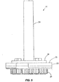
- Figs. 1-4 show a fluid control and processing system 10 including a housing 12 having a plurality of chambers 13.
- Fig. 1 shows the chambers 13 exposed for illustrative purposes.
- a top cover will typically be provided to enclose the chambers 13.
- a fluid control device 16 and a reaction vessel 18 are connected to different portions of the housing 12.
- the fluid control device in the embodiment shown is a rotary fluid control valve 16.
- the valve 16 includes a valve body 20 having a disk portion 22 and a tubular portion 24.
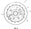
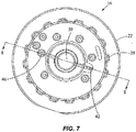
- the disk portion 22 has a generally planar external port surface 23, as best seen in Fig. 3 .
- the valve 16 is rotatable relative to the housing 12.
- the housing 12 includes a plurality of chamber ports 25 facing the external port surface 23 of the disk portion 22 of the valve 16 ( Fig. 4 ) to permit fluidic communication between the chambers 13 and the valve 16.
- An optional seal or gasket 26 is disposed between the disk portion 22 and the housing 12.
- the disk portion 22 further includes a filter or a filter stack 27 and an outer cover 28, and a toothed periphery 29.
- the cover 28 may be a rigid shell or a flexible film.
- the disk portion 22 includes a fluid processing region 30.
- the term "fluid processing region" refers to a region in which a fluid is subject to processing including, without limitation, chemical, optical, electrical, mechanical, thermal, or acoustical processing.
- chemical processing may include a catalyst; optical processing may include U.V. activation; electrical processing may include electroporation or electrophoresis or isoelectric focusing; mechanical processing may include mixing, filtering, pressurization, and cell disruption; thermal processing may include heating or cooling; and acoustical processing may include the use of ultrasound.
- the fluid processing region may include an active member, such as the filter 27, to facilitate processing of the fluid.
- active members include a microfluidic chip, a solid phase material, a filter or a filter stack, an affinity matrix, a magnetic separation matrix, a size exclusion column, a capillary tube, or the like.
- Suitable solid phase materials include, without limitation, beads, fibers, membranes, filter paper, lysis paper impregnated with a lysing agent, glass wool, polymers, or gels.
- the fluid processing region is used to prepare a sample for further processing, for instance, in the reaction vessel 18.
- the outer cover 28 encloses the fluid processing region 30 and the bottom end of the disk portion 22 of the valve 16.
- the processing region 30 includes a first fluid processing port 32 coupled to a first fluid processing channel 34, and a second fluid processing port 36 coupled to a second fluid processing channel 38.
- the first fluid processing channel 34 is coupled to a first outer conduit 40 ending at a first external port 42 at the external port surface 23, while the second fluid processing channel 38 is coupled to a second outer conduit 44 ending at a second external port 46 at the external port surface 23.
- a fluid displacement channel 48 is coupled to the first fluid processing channel 34 and first conduit 40 near one end, and to a fluid displacement region 50 at the other end.
- the first outer conduit 40 serves as a common conduit for allowing fluidic communication between the first external port 42 and either or both of the first fluid processing channel 34 and the fluid displacement channel 48.
- the processing region 30 is in continuous fluidic communication with the fluid displacement region 50.
- the external ports 42, 46 are angularly spaced from one another relative to the axis 52 of the valve 16 by about 180°.
- the external ports 42, 46 are spaced radially by the same distance from the axis 52.
- the axis 52 is perpendicular to the external port surface 23.
- the angular spacing between the external ports 42, 46 may be different.
- the configuration of the channels in the disk portion 22 may also be different in another embodiment.
- the first fluid processing channel 34 and the first outer conduit 40 may be slanted and coupled directly with the fluid displacement region 50, thereby eliminating the fluid displacement channel 48.
- the second fluid displacement channel 38 may also be slanted and extend between the second fluid processing port 36 and the second external port 46 via a straight line, thereby eliminating the second outer conduit 44.
- more channels and external ports may be provided in the valve 16.
- a crossover channel or groove 56 is desirably provided on the external port surface 23.
- the groove 56 is curved and desirably is spaced from the axis 52 by a constant radius.
- the groove 56 is a circular arc lying on a common radius from the axis 52. As discussed in more detail below, the groove 56 is used for filling the vessel.
- the fluid displacement region 50 is disposed substantially within the tubular portion 24 of the valve 16 and extends partially into the disk portion 22.
- the fluid displacement region 50 is a pumping channel or chamber.
- a fluid displacement member in the form of a plunger or piston 54 is movably disposed in the pumping chamber 50. When the piston 54 moves upward, it expands the volume of the pumping chamber 50 to produce a suction for drawing fluid into the pumping chamber 50. When the piston 54 moves downward, it decreases the volume of the pumping chamber 50 to drive fluid out of the chamber 50.
- pressurization and depressurization of the displacement region 50 may be carried out using a diaphragm, an external pneumatic or pressure control system, or the like.
- one of the external ports 42, 46 may be open and fluidicly coupled with one of the chambers 13 or reaction vessel 18, or both external ports 42, 46 may be blocked or closed. In this embodiment, at most only one of the external ports 42, 46 is fluidicly coupled with one of the chambers or reaction vessel 18. Other embodiments may be configured to permit both external ports 42, 46 to be fluidicly coupled with separate chambers or the reaction vessel 18.
- the valve 16 is rotatable with respect to the housing 12 to allow the external ports 42, 46 to be placed selectively in fluidic communication with a plurality of chambers which include the chambers 13 and the reaction vessel 18.
- the external ports 42, 46 can each switch from being an inlet port to an outlet port, and the fluid flow may pass through the processing region 30 or bypass the processing region 30.
- the first external port 42 is the inlet port so that the inlet side of the processing region 30 is closer to the fluid displacement region 50 than the outlet side of the processing region 30.
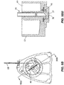
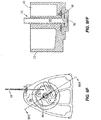
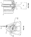
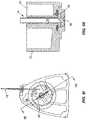
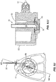
- FIGs. 9A-9LL illustrate the operation of the valve 16 for a specific protocol.
- the first external port 42 is placed in fluidic communication with a sample chamber 60 by rotating the valve 16, and the piston 54 is pulled upward to draw a fluid sample from the sample chamber 60 through the first outer conduit 40 and fluid displacement channel 48 to the fluid displacement region 50, bypassing the processing region 30.
- the.piston 54 is not shown in Figs. 9A-9LL .
- the valve 16 is then rotated to place the second external port 46 in fluidic communication with a waste chamber 64 as shown in Figs. 9B and 9BB .
- the fluid processing region 30 includes a filter or a filter stack 27 for capturing sample components (e.g., cells, spores, microorganisms, viruses, proteins, or the like) from the fluid sample as it passes therethrough.
- sample components e.g., cells, spores, microorganisms, viruses, proteins, or the like
- FIG. 09/584,327 An example of a filter stack is described in commonly assigned, copending U.S. Patent Application No. 09/584,327 , entitled “Apparatus and Method for Cell Disruption,” filed May 30, 2000.
- other active members may be provided in the processing region 30. These first two steps of capturing sample components may be repeated as desired.
- valve 16 is rotated to place the first external port 42 in fluidic communication with a wash chamber 66, and the piston 54 is pulled upward to draw a wash fluid from the wash chamber 66 into the fluid displacement region 50, bypassing the processing region 30.
- the valve 16 is then rotated to place the second external port 46 in fluidic communication with the waste chamber 64 as shown in Figs. 9D and 9DD .
- the piston 54 is pushed downward to drive the wash fluid through the fluid processing region 30 to the waste chamber 64.
- the above washing steps may be repeated as desired.
- the intermediate washing is used to remove unwanted residue within the valve 16.
- Figs. 9E and 9EE the valve 16 is rotated to place the first external port 42 in fluidic communication with a lysis chamber 70, and the piston 54 is pulled upward to draw a lysing fluid (e.g., a lysing reagent or buffer) from the lysis chamber 70 into the fluid displacement region 50, bypassing the processing region 30.
- the valve 16 is then rotated to place the second external port 46 in fluidic communication with the waste chamber 64 as shown in Figs. 9F and 9FF .
- the piston 54 is pushed downward to drive the lysing fluid through the fluid processing region 30 to the waste chamber 64.
- Figs. 9G, and 9GG the valve 16 is rotated to close the external ports 42, 46.
- the piston 54 is pushed downward to pressurize the remaining lysing fluid and the sample components captured in the fluid processing region 30. Additional energy may be applied to the mixture in the processing region 30.
- a sonic member 76 such as an ultrasonic horn may be placed in contact with the outer cover 28 to transmit sonic energy into the processing region 30 to facilitate lysing of the sample components.
- the outer cover 28 is made of a flexible film which is stretched under pressure to contact the sonic member 76 during lysing to allow transmission of the sonic energy into the processing region 30.
- the cover 28 in one embodiment is a flexible film of polymeric material such as polypropylene, polyethylene, polyester, or other polymers.
- the film may either be layered, e.g., laminates, or the films may be homogeneous. Layered films are preferred because they generally have better strength and structural integrity than homogeneous films.
- layered polypropylene films are presently preferred because polypropylene is not inhibitory to polymerase chain reaction (PCR).
- the cover 28 may comprise other materials such as a rigid piece of plastic.
- the cover 28 is an interface wall which is dome-shaped or includes stiffening ribs as shown, for example, in PCT Publication WO 00/73413 entitled “Apparatus and Method for Cell Disruption,” or commonly assigned, copending U.S. Patent Application No. 09/972,221 , entitled “Apparatus and Method for Rapid Disruption of Cells or Viruses,” filed October 4, 2001.
- the energy transmitting member that is operatively coupled to the processing region 30 for transmitting energy thereto may be an ultrasonic, piezoelectric, magnetostrictive, or electrostatic transducer.
- the energy transmitting member may also be an electromagnetic device having a wound coil, such as a voice coil motor or a solenoid device.
- the energy transmitting member be a sonic member, such as an ultrasonic horn. Suitable horns are commercially available from Sonics & Materials, Inc. having an office at 53 Church Hill, Newton, Connecticut 06470-1614, U.S.A.
- the sonic member may comprise a piezoelectric disk or any other type of ultrasonic transducer that may be coupled to the cover 28.
- the energy transmitting member may be a thermal element (e.g., a heater) for transmitting thermal energy to the processing region 30 or an electrical element for transmitting electrical energy to the processing region 30.
- multiple energy transmitting members may be employed simultaneously, e.g., simultaneously heating and sonicating the processing region to effect lysis of cells, spores, viruses, or microorganisms trapped in the processing region.
- reagent chamber 78 typically contains reagents (e.g., nucleic acid amplification reagents and probes) to be mixed with the sample. Any excess mixture is dispensed into the waste chamber 64 via the second external port 46 after rotating the valve 16 to place the port 46 in fluidic communication with the waste chamber 64, as shown in Figs. 9I and 9II . The mixture is then mixed in the reagent chamber 78 by toggling.
- reagents e.g., nucleic acid amplification reagents and probes
- the reagent chamber 78 may contain dried or lyophilized reagents that are reconstituted when mixed with fluid.
- the valve 16 is rotated to place the first external port 42 in fluidic communication with a first branch 84 coupled to the reaction vessel 18, while the second branch 86 which is coupled to the reaction vessel 18 is placed in fluidic communication with the crossover groove 56.
- the first branch 84 and second branch 86 are disposed at different radii from the axis 52 of the valve 16, with the first branch 84 having a common radius with the first external port 42 and the second branch 86 having a common radius with the crossover groove 56.
- the crossover groove 56 is also in fluidic communication with the reagent chamber 78 ( Fig. 9K ), and serves to bridge the gap between the reagent chamber 78 and the second branch 86 to provide crossover flow therebetween.
- the external ports are disposed within a range of external port radii from the axis and the crossover groove is disposed within a range of crossover groove radii from the axis, where the range of external port radii and the range of crossover groove radii are non-overlapping. Placing the crossover groove 56 at a different radius from the radius of the external ports 42, 46 is advantageous because it avoids cross-contamination of the crossover groove 56 by contaminants that may be present in the area near the surfaces between the valve 16 and the housing 12 at the radius of the external ports 42, 46 as a result of rotational movement of the valve 16.
- crossover groove 56 is a preferred arrangement that isolates the crossover groove 56 from contamination from the area near the surfaces between the valve 16 and the housing 12 at the radius of the external ports 42, 46.
- the piston 54 is pulled upward to draw the mixture in the reagent chamber 78 through the crossover groove 56 and the second branch 86 into the reaction vessel 18.
- the reaction vessel 18 is the aspiration chamber or referred to as the first chamber
- the reagent chamber 78 is the source chamber or referred to as the second chamber.
- the valve 16 is then rotated to place the second external port 46 in fluidic communication with the first branch 84 and to close the first external port 42, as shown in Figs. 9L and 9LL .
- the piston 54 is pushed downward to pressurize the mixture inside the reaction vessel 18.
- the reaction vessel 18 may be inserted into a thermal reaction chamber for performing nucleic acid amplification and/or detection.
- the two branches 84, 86 allow filling and evacuation of the reaction chamber of the reaction vessel 18.
- the vessel maybe connected to the housing 12 by ultrasonic welding, mechanical coupling, or the like, or be integrally formed with the housing 12 such as by molding.
- the use of a reaction vessel for analyzing a fluid sample is described in commonly assigned, copending U.S. Patent Application No. 09/584,328 , entitled “Cartridge for Conducting a Chemical Reaction,” filed May 30, 2000.
- a motor such as a stepper motor is typically coupled to the toothed periphery 29 of the disk portion 22 to rotate the valve 16 relative to the housing 12 for distributing fluid with high precision.
- the motor can be computer-controlled according to the desired protocol.
- a linear motor or the like is typically used to drive the piston 54 up and down with precision to provide accurate metering, and may also be computer-controlled according to the desired protocol.
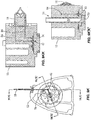
- Fig. 10 shows another valve 100 which is rotatably coupled to a fluid control channel housing or block 102.
- a reaction vessel 104 is detachably coupled to the housing 102.
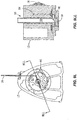
- the valve 100 is a generally tubular member with a longitudinal axis 105 as shown in Fig. 11 .
- a piston 106 is movably connected to the valve 100 to change the volume of the fluid displacement region 108 as the piston 106 is moved up and down.
- a cover 109 is placed near the bottom of the valve 100.
- a fluid processing region 110 is disposed in the valve 100 and is in continuous fluidic communication with the fluid displacement region 108.
- the valve 100 includes a pair of apertures serving as a first port 111 and a second port 112, as best seen in Fig. 11 .
- the ports 111, 112 are angularly spaced by about 120°, but the spacing may be different in alternate embodiments.
- a crossover channel or groove 114 is formed on the external surface 116 of the valve 100 and extends generally in the longitudinal direction, as seen in Fig. 10 .
- the two ports 111, 112 are disposed at different levels longitudinally offset from one another along the longitudinal axis 105, and the crossover groove 114 extends in the longitudinal direction of the axis 105 bridging the two levels of the ports 111,112.
- the housing 102 has an opening 118 for receiving the portion of the valve 100 having the ports 111, 112 and groove 114.
- the internal surface 120 around the opening 118 is shaped to cooperate with the external surface 116 of the valve 100.
- a gasket may be placed between the internal surface 120 and the external surface 116, a preferred embodiment employs tapered or conical surfaces 120, 116 that produce a sealing effect without the use of an additional gasket.
- the housing 102 includes a plurality of channels and ports and the valve 100 is rotatable around its axis 105 to allow the ports 111, 112 to be placed selectively in fluidic communication with the plurality of channels in the housing 102.
- the fluid flow in the valve 100 can change directions, and the ports 111, 112 can each switch from being an inlet port to an outlet port.
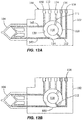
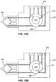
- Figs. 12A-12N illustrate the operation of the valve 100 for a specific protocol.
- the housing 102 includes a plurality of fluid channels.
- the channels are labeled as follows: reagent channel 130, lysing channel 132, sample channel 134, wash channel 136, waste channel 138, first branch 140, and second branch 142.
- the channels 130-138 extend from the internal surface 120 to one external surface 144 which is generally planar, and the branches 140, 142 extend from the internal surface 120 to another external surface 146 which is also generally planar ( Fig. 10 ).
- the first port 111 and the channels 130-134 lie on a first transverse plane that is perpendicular to the longitudinal axis 105, while the second port 112, the channels 136, 138, and the two branches 140, 142 lie on a second transverse plane that is perpendicular to the longitudinal axis 105.
- the second transverse plane is longitudinally offset from the first transverse plane.
- the second port 112, the channels 136, 138, and the branches 140, 142 are shaded to indicate that they are longitudinally offset from the first port 111 and the channels 130-134.
- the crossover groove 114 extends longitudinally to bridge the offset between the first and second transverse planes.
- a chamber body 150 is connected to the housing 102 ( Fig. 10 ), and includes the reagent chamber, lysis chamber, sample chamber, wash chamber, and waste chamber that are respectively coupled fluidicly with the channels 130-138.
- the first and second branches 140, 142 are fluidicly coupled with the reaction vessel 104.
- Fig. 12A the first port 111 is placed in fluidic communication with the sample channel 134 and the piston 106 is pulled upward to draw a fluid sample into the fluid displacement region 108 ( Fig. 11 ).
- the valve 100 is then rotated to place the second port 112 in fluidic communication with the waste channel 138 and the piston 106 is pushed downward to drive the fluid sample from the displacement region 108 through the processing region 110, and out through the waste channel 138, as shown in Fig. 12B .
- These steps are typically repeated until an entire sample is processed through the processing region 110, for instance, to capture sample components on a trapping member such as a filter.
- valve 100 is rotated to place the second port 112 in fluidic communication with the wash channel 136 to aspirate a wash fluid into the processing region 110 by pulling the piston 106 upward.
- the valve 100 is then rotated to place the second port 112 in fluidic communication with the waste channel 138 and the piston 106 is pushed downward to drive the wash fluid from the processing region 110 out through the waste channel 138.
- the above washing steps can be repeated as desired to remove unwanted residue inside the valve 100.
- the valve 100 is rotated to place the first port 111 in fluidic communication with the lysing channel 132 and the piston 106 is pulled upward to draw a lysing fluid into the fluid displacement region 108, as shown in Fig. 12E .
- the valve 110 is rotated to close both ports 111, 112.
- the piston 106 is pushed downward to push the lysing fluid into the processing region 110 and to pressurize the lysing fluid and the sample components captured in the fluid processing region 110.
- Additional energy may be applied to the mixture in the processing region 110 including, for instance, sonic energy transmitted into the processing region 110 by operatively coupling a sonic member with the cover 109 ( Fig. 11 ).
- a desired preset amount of wash fluid is aspirated into the processing region 110 from the wash channel 136 through the second port 112 to dilute the mixture.
- the valve 100 is then rotated to place the first port 111 in fluidic communication with the reagent channel 130 to discharge a preset amount of the mixture from the processing region 110 to the reagent chamber, as shown in Fig. 12H .
- the piston 106 is moved up and down to agitate and mix the mixture by toggling.
- the balance of the mixture is discharged through the second port 112 to the waste channel 138, as shown in Fig. 12I .
- Another wash is performed by drawing a wash fluid from the wash channel 136 through the second port 112 into the processing region 110 ( Fig. 12J ), and discharging the wash fluid from the processing region 110 through the second port 112 to the waste channel 138 ( Fig. 12K ).
- the valve 100 is rotated to place the second port 112 in fluidic communication with the first branch 140 coupled to the reaction vessel 104, while the second branch 142 which is coupled to the reaction vessel 104 is placed in fluidic communication with the crossover groove 114.
- the second branch 142 is longitudinal offset from the reagent channel 130.
- the crossover groove 114 extends longitudinally to bridge the offset between the second branch 142 and the reagent channel 130 to place them in fluidic communication with one another.
- the fluid processing region 110 is in fluidic communication, through the first branch 140, the reaction vessel 104, the second branch 142, and the crossover groove 114, with the reagent channel 130.
- the piston 106 By pulling the piston 106 upward, the mixture in the reagent chamber is drawn from the reagent channel 130 through the crossover groove 114 and the second branch 142 into the reaction vessel 104.
- the valve 100 is then rotated to place the second port 112 in fluidic communication with the second branch 142 and to close the first port 111, as shown in Fig. 12M .
- the piston 106 is pushed downward to pressurize the mixture inside the reaction vessel 104.
- the valve 100 In Fig. 12N , the valve 100 is rotated to close the ports 111, 112 and isolate the reaction vessel 104.
- the reaction vessel 104 may be inserted into a thermal reaction chamber for performing nucleic acid amplification and/or detection.
- the fluid control and processing system is advantageously a fully contained system that is versatile and adaptable.
- the fluid displacement region is the motivating force for moving fluid in the system.
- the fluid displacement region (motivating force) also acts as a temporary storage area for the fluid being driven through the system. While the embodiments shown employ a moving piston in the fluid displacement region as the motivating force, other mechanisms may be used including, e.g., pneumatic pump mechanisms or the like which use pressure as the motivating force without a change in volume of the fluid displacement region.
- the inlet or outlet side of the fluid processing region can address any of the chambers to permit random access to reagents and other fluids.
- Complex protocols can be programmed relatively easily into a computer controller and then executed using the versatile fluid control and processing system. A myriad of different protocols can be performed using a single platform.
- the fluid control occurs by addressing a pair of ports in the valve to place only one port at a time selectively in fluidic communication with the chambers. This is accomplished by keeping the pair of ports out of phase relative to the chambers.
- a crossover or bypass channel provides additional fluid control capability (e.g., allowing convenient filling and emptying of the reaction vessel within the closed system).
- different porting schemes may be used to achieve the desired fluid control in other embodiments.
- each include a single fluid processing region in the valve body, additional processing regions can be located in the valve body if desired. Generally, the valve body needs (n+1) ports per n processing regions.
- the use of a single valve produces high manufacturing yields due to the presence of only one failure element.
- the concentration of the fluid control and processing components results in a compact apparatus (e.g., in the form of a small cartridge) and facilitates automated molding and assembly.
- the system advantageously includes dilution and mixing capability, intermediate wash capability, and positive pressurization capability.
- the fluid paths inside the system are normally closed to minimize contamination and facilitate containment and control of fluids within the system.
- the reaction vessel is conveniently detachable and replaceable, and may be disposable in some embodiments.
- the components of the fluid control and processing system may be made of a variety of materials that are compatible with the fluids being used.
- suitable materials include polymeric materials such as polypropylene, polyethylene, polycarbonate, acrylic, or nylon.
- the various chambers, channels, ports, and the like in the system may have various shapes and sizes.
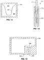
- Fig. 13 shows a soft-walled chamber 200 that may be incorporated into the fluid control and processing system.
- an on-board reagent style cartridge requires a total fluid volume of at least twice the total volume of reagents and sample combined in rigid systems.
- the use of soft-walled chambers can reduce the required volume.
- These chambers have flexible walls, and can typically be formed using films and thermoforming. An added advantage of soft walls is that venting need not be provided if the walls are sufficiently flexible to allow them to collapse when the chamber is emptied.
- a flexible sidewall 202 separates a reagent chamber 204 and a waste chamber 206.
- the volume required for waste is no more than the sum of the sample and reagents.
- the reagent chamber 204 contracts while the waste chamber 206 expands, and vice versa. This can be a closed system with no connection to the exterior.
- the configuration can reduce the overall size of the cartridge, and can allow fast change-overs of chamber volumes. It can also eliminate venting, and can cut costs by reducing the number of platforms that would otherwise need to be built with hard tooling.
- at least two of the plurality of chambers in the system are separated by a flexible wall to permit change-over of chamber volumes between the chambers.
- Fig. 14 shows a piston assembly 210 including a piston rod 212 connected to a piston shaft 214 having a smaller cross-section than the rod 212 for driving small amounts of fluids.
- the thin piston shaft 214 may bend under an applied force if it is too long.
- the piston rod 212 moves along the upper portion of the barrel or housing 216, while the piston shaft 214 moves along the lower portion of the barrel 216.
- the movement of the piston rod 212 guides the movement of the piston shaft 214, and absorbs much of the applied force so that very little bending force is transmitted to the thin piston shaft 214.
- Fig. 15 shows a side chamber 220 that may be incorporated into the system.
- the side chamber 220 includes an inlet port 222 and an outlet port 224.
- the side chamber 220 includes a filter 226 disposed at the inlet port 222. Fluid is directed to flow via the inlet port 222 into the side chamber 220 and out via the outlet port 224 for side filtering.
- the fluid may be recirculated to achieve better filtering by the filter 226.
- This prefiltering is useful to remove particles before introducing the fluid into the main chambers of the system to prevent clogging.
- the use of a side chamber is advantageous, for instance, to avoid contaminating the valve and the main chambers in the system.
- a fluid sample may be introduced into the housing 12 of the fluid control and processing system 10, which may be configured as a cartridge, by a variety of mechanisms, manual or automated.
- a measured volume of material may be placed into a receiving area of the housing 12 (e.g., one of the plurality of chambers) through an input port and a cap is then placed over the port.
- the receiving area may be covered by a rubber or similar barrier and the sample is injected into the receiving area by puncturing the barrier with a needle and injecting the sample through the needle.
- a greater amount of sample material than required for the analysis can be added to the housing 12 and mechanisms within the housing 12 can effect the precise measuring and aliquoting of the sample needed for the specified protocol.
- tissue biopsy material such as tissue biopsy material, soil, feces, exudates, and other complex material
- secondary device or accessory into the housing causing a mechanical action which effects a function such as mixing, dividing, or extraction.
- tissue biopsy material such as tissue biopsy material, soil, feces, exudates, and other complex material
- tissue biopsy material such as soil, feces, exudates, and other complex material
- a piece of tissue may be placed into the lumen of a secondary device that serves as the input port cap. When the cap is pressed into the port, the tissue is forced through a mesh that slices or otherwise divides the tissue.
- a syringe or sipper may be integrated into the device to provide a means for moving a sample directly into the housing.
- the device may include a venous puncture needle and a tube forming an assembly that can be used to acquire a sample. After collection, the tube and needle are removed and discarded, and the housing 12 is then placed in an instrument to effect processing. The advantage of such an approach is that the operator or the environment is not exposed to pathogens.
- the input port can be designed with a consideration of appropriate human factors as a function of the nature of the intended specimen.
- respiratory specimens may be acquired from the lower respiratory tract as expectorants from coughing, or as swab or brush samples from the back of the throat or the nares.
- the input port can be designed to allow the patient to cough directly into the housing 12 or to otherwise facilitate spitting of the expectorated sample into the housing.
- brush or swab specimens the specimen is placed into the input port where features of the port and closure facilitate the breaking off and retaining of the end of the swab or brush in the cartridge receiving area.
- the housing 12 includes one or more input tubes or sippers that may be positioned in a sample pool so that the sample material flows into the housing 12.
- a hydrophilic wicking material can function to draw a sample into the device.
- the entire cartridge can be immersed directly into the sample, and a sufficient amount of sample is absorbed into the wicking material and wicks into the housing 12.
- the housing is then removed, and can be transported to the laboratory or analyzed directly using a portable instrument.
- tubing can be utilized so that one end of the tube is in direct communication with the housing to provide a fluidic interface with at least one chamber and the other end is accessible to the external environment to serve as a receiver for sample.
- the tube can then be placed into a sample and serve as a sipper.
- the device may include a variety of features for collecting a sample from various different sources and for moving the sample into the housing 12, thereby reducing handling and inconvenience.
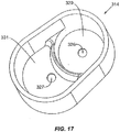
- Fig. 16 shows a fluid control and processing system 310 including a housing 312 having a plurality of chambers 313 wherein one of the chambers is a processing chamber 314.
- the housing 312 includes a plurality of chamber ports 325 configured to communicate with a fluid control device such as a rotary fluid control valve similar to the rotary valve 16 in the system 10 of Figs. 1-4 .
- the valve has a fluid displacement region similar to the fluid displacement region 50 in the system 10.
- the chambers 313 may include the same chambers as in the embodiment of Figs. 1-4 (i.e., sample chamber 60, waste chamber 64, wash chamber 66, lysis chamber 70, reagent chamber 78, and reaction vessel 18).
- the housing 312 also includes a fluid processing region or active region similar to the fluid processing region 30 of system 10 in Figs. 1-4 . In such a configuration, the chamber ports 325 will face the external port surface of the disk portion of a rotary fluid control valve
- the processing chamber 314 has a first port 326 and a second port 327.
- the first port 326 may be an inlet port for taking in fluid
- the second port 327 may be an outlet port for discharging fluid from the processing chamber 314.
- the processing chamber 314 typically is integrally formed or built into the main body of the housing 312, so that the inlet and outlet ports of the processing chamber are two of the chamber ports.
- the processing chamber 314 may be formed as a separate member that can be inserted into the main body of the housing 312, the inserted member having inlet and outlet ports that align with two of the chamber ports.
- the processing chamber 314 may contain a processing chamber material, such as an enrichment material or medium or a depletion material or medium.
- An enrichment material captures a target such as an analyte from the fluid that passes through the processing chamber 314.
- a depletion material traps or retains unwanted material from the fluid that passes through the processing chamber 314.
- the enrichment or depletion material may comprise one or more solid phase materials.
- the solid phase materials may include beads, fibers, membranes, filter paper, glass wool, polymers, and gels.
- enrichment materials may include chromatographic materials, more particularly absorptive phase materials, such as reverse phase materials, ion-exchange materials, or affinity chromatographic materials in which a binding member is covalently bound to an insoluble matrix.
- the binding member may be group specific (e.g., a lectin, enzyme cofactor, Protein A and the like) or substance specific (e.g., antibody or binding fragment thereof, antigen for a particular antibody of interest, oligonucleotide and the like).
- the insoluble matrix to which the binding member is bound may be particles, such as porous glass or polymeric beads, networks of glass strands or filaments, a plurality of narrow rods or capillaries, and the like.
- the insoluble matrix may include beads functionalized with antibodies for capturing antigens or haptens for an immunoassay procedure.
- coated particles or other insoluble matrices may employ a coated/impregnated membrane which provides for selective retention of the analyte comprising fraction of a fluid sample while allowing the remainder of the sample to flow through the membrane and out of the processing chamber.
- a coated/impregnated membrane which provides for selective retention of the analyte comprising fraction of a fluid sample while allowing the remainder of the sample to flow through the membrane and out of the processing chamber.
- an enrichment material is a gel medium, which can be used to provide for a diversity of different sieving capabilities.
- the enrichment channel through the processing chamber 314 serves to enrich a particular analyte comprising fraction of a liquid sample.
- Frits such as glass frits may be used to retain the material in the processing chamber.
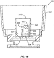
- Figs. 18-23 show two frits 330, 332 disposed inside the processing chamber 314. In the embodiment shown, the frits 330, 332 are held in place by a retaining structure or member 336.
- the retaining member 336 may be configured as a processing module or an insert that can be easily snapped into place in a receiving area of the processing chamber 314 and can be conveniently removed as desired. As shown in Fig.
- the processing chamber 314 includes a receiving area 329 for receiving a processing module containing an enrichment material or a depletion material.
- the processing module may comprise a column containing a separation material or a structure containing a separation channel for capillary electrophoresis or isoelectric focusing.
- the processing chamber 314 has a collection area 331 for receiving fluid that has flowed through the processing module 336.
- the processing module 336 preferably includes a spout 333 that directs the fluid into the collection area 331.
- the processing module includes a first frit 330 that is disposed adjacent the first port 326, and the second frit 332 is spaced from the first frit 330 to provide a space 338 for the enrichment material or depletion material.
- the fluid enters the processing chamber 314 through the first port 326, passes through the first frit 330, the enrichment material or depletion material in the space 338, and the second frit 332, and then by gravity flows to the collection area 331 of the processing chamber above the second port 327 and exits the processing chamber 314 through the port 327.
- the space 338 serves as another fluid processing region.
- a sample fluid is drawn from the sample chamber by rotating the valve to place the fluid displacement region in fluidic communication with the sample chamber via the first external port.
- This is illustrated for the system 10 of Figs. 1-4 in Figs. 9A and 9AA , which is generally the same as the system 310 of Figs. 16-23 except for the additional processing chamber 314 in the system 310.
- the sample fluid bypasses the fluid processing region (region 30 in system 10), and enters the fluid displacement region (region 50 in system 10).
- the valve (valve 16 in system 10) is rotated to place the first external port in fluidic communication with the processing chamber 314.
- the sample fluid is driven from the fluid displacement region into the processing chamber 314 via the inlet port 326, bypassing the fluid processing region.
- the analyte comprising sample fraction will be retained by the enrichment material such as a chromatographic material in the processing chamber 314.
- the remaining waste portion of the fluid is drawn out of the processing chamber 314 through the outlet port 327 and into the fluid displacement region of the valve by rotating the valve to place the first external port in fluidic communication with the outlet port 327 of the processing chamber 314.
- the valve is then rotated to place the first external port in fluidic communication with the waste chamber (chamber 64 in system 10), and the waste fluid is driven from the fluid displacement region into the waste chamber.
- An elution liquid may then flow through the enrichment material in the processing chamber 314 to release the enriched sample fraction from the enrichment material and carry it from the processing chamber 314 to another chamber or another region such as an active region.
- the elution liquid may be first drawn into the fluid displacement region of the valve from another chamber, and then driven from the fluid displacement region into the inlet port 326 of the processing chamber 314 by manipulating the rotary valve.
- the elution liquid and the released enriched sample fraction may be drawn from the processing chamber 314 via the outlet port 327, either into the fluid displacement region through the first external port (port 42 in system 10) bypassing the fluid processing region, or through the fluid processing region (region 30 in system 10) and into the fluid displacement region through the second external port (port 46 in system 10).
- the rotary valve may be further manipulated to transfer the fluid to other chambers or regions of the system 310.
- a depletion material is provided in the processing chamber 314 for trapping or removing unwanted material from a sample fluid.
- the valve can be used to transfer the sample fluid from the sample chamber to the processing chamber 314 as described above.
- the unwanted materials such as cellular debris, contaminants, or amplification inhibitors are depleted from the fluid.
- the remaining fluid is drawn out of the processing chamber 314 through the outlet port 327 by rotating the valve to place the fluid displacement region in fluidic communication with the outlet port 327.
- the fluid may be drawn through the second external port (port 46 in system 10) first into the fluid processing region (region 30 in system 10) and then into the fluid displacement region of the valve.
- the fluid may be drawn through the first external port (port 42 in system 10) into the fluid displacement region bypassing the fluid processing region.
- the fluid may subsequently be driven from the fluid displacement region into another chamber or region of the system 310 by manipulating the rotary valve.
- the processing chamber 314 may house liquid phase materials such as, for example, ficoll, dextran, polyethylene glycol (PEG), sucrose, and the like.
- liquid phase materials such as, for example, ficoll, dextran, polyethylene glycol (PEG), sucrose, and the like.
- the system 310 becomes more versatile, and is capable of performing additional steps of sample preparation other than those performed in the active region or processing region in the valve body (e.g., processing region 30 in Fig. 8 ), to achieve multi-staged filtration, consecutive functions, and the like in a single device.
- the processing chamber may be fluidicly coupled with an external fluid volume to facilitate large volume processing.
- the processing chamber may also be fluidicly coupled with an external chamber that contains materials that are not desirable inside the main body 312 of the fluid processing system 310.
- each processing region in the processing chambers may each contain enrichment materials or depletion materials.
- each processing region may contain one or more such materials.
- a filter e.g., the filter or filter stack 27 in Fig. 8
- beads may be placed in a processing region to remove unwanted materials such as cellular debris from the sample or for accomplishing concentration of cells.
- the filter or beads may be used to bind specific targets such as particular molecules in the sample, or to remove specific targets such as proteins, inhibitors, or the like.
- a processing region includes a filter and another solid phase material such as beads, fibers, or wool, for molecular isolation of molecular targets or molecular removal of molecular materials.
- a processing region may include different types of beads such as magnetic beads, glass beads, polymeric beads, and the like.
- the beads can be used for cell capture, cell lysis, binding of analyte, binding of unwanted material, or the like.
- a single type of beads may be used to perform two or more of the functions of cell capture, cell lysis, binding of analyte, and binding of unwanted material.
- cells can be adhered to the beads and lysed to release their nucleic acid content, and the lysate together with the released nucleic acid can be moved to a separate region or chamber for further processing, leaving behind the beads and their adherent cellular debris.
- a separation channel is provided for performing capillary electrophoresis (CE), isoelectric focusing (IEF), or the like. This may be done before or after nucleic acid amplification.
- CE capillary electrophoresis
- IEF isoelectric focusing
- the separation channel may be a separate member that is inserted into a chamber of the fluid processing system, may be formed as a microchannel in the housing of the system, or may be built into one of the chambers of the system.
- Fig. 24 shows a separation channel or region 350 in the fluid control and processing system 354.
- the separation channel 350 is typically formed as a separate member that is assembled into the system 354 and may in some embodiments be disposed in a chamber 352. Alternatively, the separation channel 350 may be integrally formed or built into the system 354.
- the separation channel 350 may be a thin channel or a capillary coupled between at least two electrodes, which in the specific embodiment shown include two metal tubes 356, 358.
- the lower end of the channel 350 is fluidicly coupled to a lower reservoir 361 which is fluidicly coupled to a chamber port or reservoir port 360, while the upper end of the channel 350 is fluidicly coupled to a vented reservoir 362 provided in a support structure 366 for supporting the separation channel 350.
- the metal tubes 356, 358 serve as electrodes to receive electrical energy and apply an electric field to the fluid in the separation channel 350.
- Conductive wires in contact with the metal tubes 356, 358 may be molded into plastic and lead to respective contact areas on the external surface of the housing of the system 354.
- a voltage source may then be connected to the contact areas to apply a voltage difference between the contact areas and thus between the electrodes.
- electrodes may be provided as part of an external instrument for applying the electric field, and be dipped into reservoirs at the ends of the separation channel 350.
- the sample fluid is typically pumped by the piston 368 of the valve 370 from the fluid displacement region 372 through one of the external ports of the valve body (e.g., the external port 342) to the separation channel 350 via the reservoir port 360 and reservoir 361.
- a sample plug is injected into the separation channel 350, and the remaining portion of the sample fluid in the reservoir 361 may then be drawn via the chamber port 360 into the fluid displacement region 372 of the valve 370 by the piston 368.
- the reservoir 362 may be used to introduce buffer, elution solvent, reagent, rinse and wash solutions, or the like into the electrophoretic flow path of the separation channel 350.
- Entities in the sample plug such as molecules, particles, cells, and the like are moved through a medium contained in the separation channel 350 under the influence of the applied electric field.
- the entities may be moved through the medium under the direct influence of the applied electric field or as a result of bulk fluid flow through the pathway resulting from the application of the electric field such as an electroosmotic flow.
- the bands are detected, for instance, optically by a single point detector disposed at a fixed location or by a scanning detector that scans along the length of the channel 350.
- a portion of the housing may be optically transmissive or transparent.
- the detector may be inserted into the housing and placed adjacent the channel 350 (e.g., in a chamber which houses the channel 350).
- an amplified product e.g., nucleic acid amplified by PCR
- the separation channel 350 is prefilled with a separation material such a gel or buffer.
- a voltage is applied via the electrodes 356, 358 to inject a sample plug from the reservoir 361.
- the rest of the sample is then removed from the reservoir 361.
- a buffer such as an electrolyte solution is introduced into the reservoir 361.
- a voltage difference is applied between the electrodes 356, 358 to form an electric field that induces flow of a sample plug through the separation channel 350 and separates the sample plug therein into species bands, which are detected using, for instance, a single-point optical detector or a scanning detector.
- Fig. 25 shows the valve 416 of another system 410 which has a housing with a plurality of chambers similar to the system 10 of Figs. 1-4 , except that the valve 416 has only one external port 442.
- the valve 416 includes a valve body 420 having a disk portion 422 and a tubular portion 424.
- the disk portion 422 has a generally planar external port surface 423.
- the valve 416 is rotatable relative to the housing 412 of the system 410 (see Fig. 26A and 26AA ).
- the housing 412 includes a plurality of chamber ports facing the external port surface 423 of the disk portion 422 of the valve 416 to permit fluidic communication between the chambers of the housing 412 and the valve 416.
- the disk portion 422 includes a fluid processing region 430, a first flow channel 440 extending between the external port 442 and the fluid processing region 430, and a second flow channel 438 extending between the fluid processing region 430 and a fluid displacement region 450 in the tubular portion 424 of the valve 416.
- the fluid processing region 430 is in continuous fluidic communication with the fluid displacement region 450.
- An outer cover 428 is placed over the fluid processing region 430.
- the fluid processing region 430 may be used to subject a fluid flowing therethrough to various acoustical, optical, thermal, electrical, mechanical, or chemical processing.
- a fluid displacement member in the form of a plunger or piston 454 is movably disposed in the displacement region 450 of the tubular portion 424 to move up and down along the axis 452.
- the piston 454 moves upward, it expands the volume of the displacement region 450 to produce a suction for drawing fluid into the region 450.
- the piston 454 moves downward, it decreases the volume of the displacement region 450 to drive fluid out of the region 450.
- the external port 442 may be fluidicly coupled with one of the chambers or reaction vessel in the housing 412.
- the external port 442 is either an inlet port or an outlet port.
- FIGs. 26A-26EE illustrate the operation of the valve 416 for a specific protocol.
- the external port 442 is placed in fluidic communication with a sample chamber 460 by rotating the valve 416, and the piston 454 is pulled upward to draw a fluid sample from the sample chamber 460 through the first flow channel 440, the fluid processing region 430, and the second flow channel 438 and into the fluid displacement region 450.
- the piston 454 is not shown in Figs. 26A-26EE .
- the valve 416 is then rotated to place the external port 442 in fluidic communication with a storage chamber 470 which contains a lysing fluid (e.g., a lysing reagent or buffer).
- a lysing fluid e.g., a lysing reagent or buffer.
- the piston 454 is pushed downward to transfer the fluid sample from the fluid displacement region 450 to the storage chamber 470.
- the piston 454 is then pulled upward to draw the fluid sample and lysing fluid from the storage chamber 470 to the fluid displacement region 450.
- the lysing fluid mixes with the sample and effects lysis of cell or viruses in the sample. Additional energy may be applied to the processing region 430 to assist the lysing process.
- a sonic member 476 such as an ultrasonic horn may be placed in contact with the outer cover 428 to transmit ultrasonic energy into the processing region 430 to facilitate lysing of cells or viruses of the fluid sample as the fluid flows from the fluid displacement region 450 to the storage chamber 470 and/or from the storage chamber 470 back to the fluid displacement region 450.
- the outer cover 428 in one preferred embodiment is an interface wall which is dome-shaped or includes stiffening ribs.
- valve 416 is rotated to place the external port 442 in fluidic communication with a reagent chamber 478, and the piston 454 is pushed downward to force the lysate to flow from the fluid processing region 430 to the reagent chamber 478.
- the reagent chamber 478 typically contains reagents (e.g., PCR reagents and fluorescent probes) to be mixed with the fluid sample. The fluids are then mixed in the reagent chamber 478 by toggling the mixture between the fluid displacement region 450 and the reagent chamber 478 as the piston 454 is moved up and down.
- the valve 416 is rotated to place the external port 442 in fluidic communication with a first branch 484 coupled to the reaction vessel 418, while the second branch 486 which is coupled to the reaction vessel 418 is placed in fluidic communication with the crossover groove 456.
- the first branch 484 and second branch 486 are disposed at different radii from the axis 452 of the valve 416, with the first branch 484 having a common radius with the external port 442 and the second branch 486 having a common radius with the crossover groove 456.
- the crossover groove 456 is also in fluidic communication with the reagent chamber 478 ( Fig.
- the external port is disposed within a range of external port radii from the axis and the crossover groove is disposed within a range of crossover groove radii from the axis, where the range of external port radii and the range of crossover groove radii are non-overlapping. Placing the crossover groove 456 at a different radius from the radius of the external port 442 is advantageous because it avoids cross-contamination of the crossover groove 456 by contaminants that may be present in the area near the surfaces between the valve 416 and the housing 412 at the radius of the external port 442 as a result of rotational movement of the valve 416.
- the piston 454 is pulled upward to draw the mixture in the reagent chamber 478 through the crossover groove 456 and the second branch 486 into the reaction vessel 418.
- the reaction vessel 418 is the aspiration chamber or referred to as the first chamber
- the reagent chamber 478 is the source chamber or referred to as the second chamber.
- the valve 416 is then rotated to place the external port in fluidic communication with the first branch 484, as shown in Figs. 26E and 26EE .
- the piston 454 is pushed downward to pressurize the mixture inside the reaction vessel 418.
- the reaction vessel 418 may be inserted into a thermal reaction chamber for performing nucleic acid amplification and/or detection.
- the two branches 484, 486 allow filling and evacuation of the reaction chamber of the reaction vessel 418.
- the fluid control and processing system 410 of Figs. 26-26EE is modified from the system 10 of Figs. 1-9LL to provide only one external port.
- the valve 100 of Figs. 10-12 may also be modified to provide only one external port by removing one of the two external ports 111, 112 and reconfiguring the fluid channels 130-138 and branches 140, 142 between the valve 100 and the various chambers and reaction vessel 104.
Landscapes
- Chemical & Material Sciences (AREA)
- Health & Medical Sciences (AREA)
- Analytical Chemistry (AREA)
- General Health & Medical Sciences (AREA)
- Hematology (AREA)
- Clinical Laboratory Science (AREA)
- Chemical Kinetics & Catalysis (AREA)
- Life Sciences & Earth Sciences (AREA)
- Physics & Mathematics (AREA)
- Biochemistry (AREA)
- General Physics & Mathematics (AREA)
- Immunology (AREA)
- Pathology (AREA)
- Dispersion Chemistry (AREA)
- Hydrology & Water Resources (AREA)
- Automatic Analysis And Handling Materials Therefor (AREA)
- Sampling And Sample Adjustment (AREA)
- Apparatus Associated With Microorganisms And Enzymes (AREA)
Claims (28)
- Fluidsteuerungs- und -verarbeitungssystem (310) zur Steuerung eines Fluidflusses einer Fluidprobe zwischen einer Vielzahl von Kammern (313), wobei das System Folgendes umfasst:ein Gehäuse (312), das die Vielzahl von Kammern (313) enthält;einen Ventilkörper (20), der einen Einzel-Hauptfluidverarbeitungsbereich (30) umfasst, der kontinuierlich mit einem Einzel-Fluidverdrängungsbereich (50) fluidverbunden ist, wobei der Fluidverdrängungsbereich (50) dekomprimierbar ist, um Fluid in den Fluidverdrängungsbereich (50) zu saugen, und komprimierbar ist, um Fluid aus dem Fluidverdrängungsbereich (50) auszustoßen, wobei der Ventilkörper (20) eine Vielzahl externer Anschlüsse (42, 46) umfasst, wobei der Hauptfluidverarbeitungsbereich (30) mit zumindest einem externen Anschluss fluidverbunden ist, wobei der Fluidverdrängungsbereich (50) mit zumindest einem externen Anschluss (42, 46) des Ventilkörpers (20) fluidverbunden ist, und der Ventilkörper (20) in Bezug auf die Vielzahl von Kammern (313) drehbar einstellbar ist, um zumindest einen externen Anschluss wahlweise mit der Vielzahl von Kammern (313) in Fluidkommunikation zu setzen, wobei der Ventilkörper (20) einen Scheibenabschnitt (22) und einen Rohrabschnitt (24) umfasst, wobei der Einzel-Hauptfluidverarbeitungsbereich (30) in dem Scheibenabschnitt (22) enthalten ist, und der Fluidverdrängungsbereich (50) in dem Rohrabschnitt (24) enthalten ist, wobei der Scheibenabschnitt (22) eine planare externe Anschlussoberfläche (23) aufweist,wobei zumindest eine aus der Vielzahl von Kammern (313) eine Verarbeitungskammer (314) ist, wobei die Verarbeitungskammer (314) einen ersten Anschluss (326) und einen zweiten Anschluss (327) umfasst, um mit zumindest einem der externen Anschlüsse (42, 46) des Ventilkörpers (20) wahlweise zu kommunizieren, wobei die Verarbeitungskammer (314) einen zusätzlichen Fluidverarbeitungsbereich bereitstellt, wobei die Verarbeitungskammer (314) ein Fluidverarbeitungsmaterial enthält, das ein Anreicherungsmaterial, das ein Target von der Fluidprobe einfängt, oder ein Abreicherungsmaterial ist, das ungewolltes Material von der Fluidprobe fängt.
- System nach Anspruch 1, wobei der Hauptfluidverarbeitungsbereich (30) mit zumindest zwei der externen Anschlüsse (42, 46) fluidverbunden ist, und der Ventilkörper (20) in Bezug auf das Gehäuse (312) drehbar einstellbar ist, so dass die externen Anschlüsse (42, 46) mit der Vielzahl von Kammern (313) wahlweise in Fluidkommunikation gesetzt werden können.
- System nach Anspruch 1, wobei das Gehäuse außerdem Folgendes umfasst:
zumindest einen Trennkanal und wobei der Ventilkörper (20) in Bezug auf das Gehäuse (312) drehbar einstellbar ist, so dass zumindest ein externer Anschluss (42, 46) mit der Vielzahl von Kammern (313) und mit dem zumindest einen Trennkanal wahlweise in Fluidkommunikation gesetzt werden kann. - System nach Anspruch 1, wobei das Fluidverarbeitungsmaterial zumindest ein Festphasenmaterial umfasst.
- System nach Anspruch 4, wobei das Festphasenmaterial zumindest eines aus Kügelchen, Fasern, Membranen, Filterpapier, Glaswolle, Polymeren und Gelen umfasst.
- System nach Anspruch 1, wobei das Fluidverarbeitungsmaterial ein Filter und Kügelchen umfasst.
- System nach Anspruch 6, wobei das Fluidverarbeitungsmaterial zumindest zwei Typen von Kügelchen umfasst.
- System nach Anspruch 7, wobei die zumindest zwei Typen von Kügelchen zumindest zwei verschiedenen Funktionen ausführen, die aus der aus Zelleinfang, Zelllyse, Analytenbindung und Bindung von ungewünschtem Material bestehenden Gruppe ausgewählt sind.
- System nach Anspruch 1, wobei der Hauptfluidverarbeitungsbereich (30) ein Festphasenmaterial enthält, das zumindest zwei verschiedene Funktionen ausführt, die aus der aus Zelleinfang, Zelllyse, Analytenbindung und Bindung von ungewünschtem Material bestehenden Gruppe ausgewählt sind.
- System nach Anspruch 9, wobei das Fluidverarbeitungsmaterial zumindest ein Flüssigphasenmaterial umfasst.
- System nach Anspruch 10, wobei das Flüssigphasenmaterial zumindest eines aus Ficoll, Dextran, Polyethylenglykol und Saccharose umfasst.
- System nach Anspruch 9, wobei das Fluidverarbeitungsmaterial in dem zusätzlichen Fluidverarbeitungsbereich durch eine oder mehrere Fritten enthalten ist.
- System nach Anspruch 2, wobei die externen Anschlüsse (42, 46) auf einer im Allgemeinen planaren externen Anschlussoberfläche (23) des Ventilkörpers (20) angeordnet sind, und wobei der Ventilkörper (20) um eine Achse (52) und in Bezug auf die Vielzahl von Kammern (313) drehbar ist, so dass die externen Anschlüsse (42, 46) mit der Vielzahl von Kammern (313) wahlweise in Fluidkommunikation gesetzt werden können, wobei die Achse (52) normal auf die externe Anschlussoberfläche (23) steht und die externen Anschlüsse (42, 46) von der Achse (52) durch einen gemeinsamen Radius beabstandet sind.
- System nach Anspruch 1, wobei der Hauptfluidverarbeitungsbereich (30) einen Typ Kügelchen enthält, der zumindest zwei verschiedene Funktionen ausführt, die aus der aus Zelleinfang, Zelllyse, Analytenbindung und Bindung von ungewünschtem Material bestehenden Gruppe ausgewählt sind.
- System nach Anspruch 1, wobei die Verarbeitungskammer (314) einen Aufnahmebereich (329) umfasst, um ein Verarbeitungsmodul (336) aufzunehmen, das ein Anreicherungsmaterial, das ein Target von der Fluidprobe einfängt, oder ein Abreicherungsmaterial, das ungewolltes Material von der Fluidprobe fängt, enthält.
- System nach Anspruch 15, wobei die Verarbeitungskammer außerdem einen Sammelbereich (331) umfasst, um Fluid, das durch das Verarbeitungsmodul (336) geflossen ist, aufzunehmen, und wobei das Verarbeitungsmodul (336) Mittel zum Halten des Anreicherungs- oder Abreicherungsmaterials in dem Verarbeitungsmodul (336) und einen Ausguss (333) zum Lenken des Fluids in den Sammelbereich (331) umfasst.
- System nach einem der Ansprüche 1 bis 3, wobei zumindest eine der Kammern (313) eine Reagenskammer (78) ist, die getrocknete oder gefriergetrocknete Reagenzien umfasst.
- Fluidsteuerungs- und -verarbeitungssystem (354) zur Steuerung eines Fluidflusses einer Fluidprobe unter einer Vielzahl von Kammern, das Folgendes umfasst:ein Gehäuse, das eine Vielzahl von Kammern und zumindest einen Trennkanal (350) aufweist; undeinen Ventilkörper, der einen Einzel-Hauptfluidverarbeitungsbereich umfasst, der kontinuierlich mit einem Einzel-Fluidverdrängungsbereich (372) fluidverbunden ist, wobei der Fluidverdrängungsbereich (372) dekomprimierbar ist, um Fluid in den Fluidverdrängungsbereich (372) zu saugen, und komprimierbar ist, um Fluid aus dem Fluidverdrängungsbereich (372) auszustoßen, wobei der Ventilkörper zumindest einen externen Anschluss (342) umfasst, wobei der Hauptfluidverarbeitungsbereich mit dem zumindest einen externen Anschluss (342) fluidverbunden ist, wobei der Fluidverdrängungsbereich (372) mit dem zumindest einen externen Anschluss (342) des Ventilkörpers fluidverbunden ist, und der Ventilkörper in Bezug auf das Gehäuse drehbar einstellbar ist, so dass der zumindest eine externe Anschluss (342) wahlweise mit der Vielzahl von Kammern und mit dem zumindest einen Trennkanal (350) in Fluidkommunikation gesetzt werden kann, wobei der Ventilkörper einen Scheibenabschnitt und einen Rohrabschnitt aufweist, wobei der Einzel-Hauptfluidverarbeitungsbereich in dem Scheibenabschnitt enthalten ist, und der Fluidverdrängungsbereich (372) in dem Rohrabschnitt enthalten ist, wobei der Scheibenabschnitt (22) eine planare externe Anschlussoberfläche (23) aufweist.
- System (310) nach Anspruch 3 oder 18, das außerdem eine Vielzahl von Elektroden umfasst, die mit dem Gehäuse verbunden sind, um über zumindest einen Abschnitt des Trennkanals (350) ein elektrisches Feld anzulegen.
- System nach Anspruch 19, wobei die Elektroden ein Paar Metallrohre (356, 358) an den zwei entgegengesetzten Enden des Trennkanals (350) umfassen.
- System nach Anspruch 3 oder 18, das außerdem Sammelbehälter (361, 362), die mit entgegengesetzten Enden des Trennkanals (350) fluidverbunden sind, und einen Sammelbehälteranschluss (360) umfasst, der mit einem der Sammelbehälter (361, 362) fluidverbunden ist, um mit dem zumindest einen externen Anschluss (342) des Ventilkörpers zu kommunizieren.
- System nach Anspruch 18, wobei zumindest eine der Kammern eine Reagenskammer ist, die getrocknete oder gefriergetrocknete Reagenzien enthält.
- Verfahren zur Steuerung eines Fluidflusses zwischen dem Ventilkörper (20) und der Vielzahl von Kammern (313) eines Systems (310), wie in einem der Ansprüche 1 bis 17 beschrieben, wobei das Verfahren Folgendes umfasst:
das drehbare Einstellen des Ventilkörpers (20) in Bezug auf die Vielzahl von Kammern (313), um zumindest einen externen Anschluss (42, 46) mit der Vielzahl von Kammern (313) wahlweise in Fluidkommunikation zu setzen. - Verfahren zur Steuerung des Fluidflusses der Fluidprobe eines Systems nach Anspruch 18, zwischen einem Ventil (370), der Vielzahl von Kammern und dem zumindest einen Trennkanal (350), wobei das Ventil (370) den zumindest einen externen Anschluss (342) und den Einzel-Fluidverdrängungsbereich (372) umfasst, der kontinuierlich mit dem Einzel-Hauptfluidverarbeitungsbereich fluidverbunden ist, der mit dem zumindest einen externen Anschluss (342) fluidverbunden ist, wobei das Ventil (370) den Scheibenabschnitt und den Rohrabschnitt aufweist, wobei der Einzel-Hauptfluidverarbeitungsbereich in dem Scheibenabschnitt enthalten ist und der Fluidverdrängungsbereich (372) in dem Rohrabschnitt enthalten ist, wobei das Verfahren Folgendes umfasst:
das drehbare Einstellen des Ventils (370) in Bezug auf die Vielzahl von Kammern und den zumindest einen Trennkanal (350), um den zumindest einen externen Anschluss (342) mit der Vielzahl von Kammern und dem Trennkanal (350) wahlweise in Fluidkommunikation zu setzen. - Verfahren nach Anspruch 24, das außerdem das Anlegen eines elektrischen Felds über zumindest einen Abschnitt des Trennkanals (350) umfasst.
- Verfahren nach Anspruch 24, wobei der externe Anschluss (342) mit dem Trennkanal (350) über einen Sammelbehälter (361) in Fluidkommunikation gesetzt wird, der mit einem Ende des Trennkanals (350) fluidverbunden ist, wobei der Sammelbehälter (361) einen Sammelbehälteranschluss (360) zum Kommunizieren mit dem zumindest einen externen Anschluss (342) des Ventils aufweist.
- Verfahren nach Anspruch 24, das außerdem das optische Detektieren von Speziesbanden in dem Trennkanal (350) umfasst.
- Verfahren nach Anspruch 24, wobei das Ventil (370), die Vielzahl von Kammern und der zumindest eine Trennkanal (350) einem System (354) wie in einem der Ansprüche 18 bis 22 definiert angehören.
Applications Claiming Priority (3)
| Application Number | Priority Date | Filing Date | Title |
|---|---|---|---|
| US10/084,409 US8048386B2 (en) | 2002-02-25 | 2002-02-25 | Fluid processing and control |
| EP03711029.3A EP1487579B1 (de) | 2002-02-25 | 2003-02-14 | Fluidverarbeitung und -steuerung |
| PCT/US2003/004352 WO2003072253A1 (en) | 2002-02-25 | 2003-02-14 | Fluid processing and control |
Related Parent Applications (2)
| Application Number | Title | Priority Date | Filing Date |
|---|---|---|---|
| EP03711029.3A Division EP1487579B1 (de) | 2002-02-25 | 2003-02-14 | Fluidverarbeitung und -steuerung |
| EP03711029.3A Division-Into EP1487579B1 (de) | 2002-02-25 | 2003-02-14 | Fluidverarbeitung und -steuerung |
Publications (2)
| Publication Number | Publication Date |
|---|---|
| EP3498375A1 EP3498375A1 (de) | 2019-06-19 |
| EP3498375B1 true EP3498375B1 (de) | 2021-04-21 |
Family
ID=27753470
Family Applications (2)
| Application Number | Title | Priority Date | Filing Date |
|---|---|---|---|
| EP19156251.1A Expired - Lifetime EP3498375B1 (de) | 2002-02-25 | 2003-02-14 | Fluidverarbeitung und -steuerung |
| EP03711029.3A Expired - Lifetime EP1487579B1 (de) | 2002-02-25 | 2003-02-14 | Fluidverarbeitung und -steuerung |
Family Applications After (1)
| Application Number | Title | Priority Date | Filing Date |
|---|---|---|---|
| EP03711029.3A Expired - Lifetime EP1487579B1 (de) | 2002-02-25 | 2003-02-14 | Fluidverarbeitung und -steuerung |
Country Status (8)
| Country | Link |
|---|---|
| US (8) | US8048386B2 (de) |
| EP (2) | EP3498375B1 (de) |
| JP (9) | JP4648627B2 (de) |
| CN (1) | CN1325167C (de) |
| AU (1) | AU2003215214B2 (de) |
| CA (3) | CA3052389C (de) |
| ES (1) | ES2732956T3 (de) |
| WO (1) | WO2003072253A1 (de) |
Families Citing this family (200)
| Publication number | Priority date | Publication date | Assignee | Title |
|---|---|---|---|---|
| US8048386B2 (en) * | 2002-02-25 | 2011-11-01 | Cepheid | Fluid processing and control |
| US7214320B1 (en) | 2002-08-08 | 2007-05-08 | Nanostream, Inc. | Systems and methods for high throughput sample analysis |
| US6812458B2 (en) * | 2002-08-08 | 2004-11-02 | Nanostream, Inc. | Systems and methods for high-throughput microfluidic sample analysis |
| US20040120861A1 (en) * | 2002-10-11 | 2004-06-24 | Affymetrix, Inc. | System and method for high-throughput processing of biological probe arrays |
| US6936167B2 (en) * | 2002-10-31 | 2005-08-30 | Nanostream, Inc. | System and method for performing multiple parallel chromatographic separations |
| US20040157336A1 (en) * | 2002-11-14 | 2004-08-12 | Affymetrix, Inc. | Automated fluid control system and process |
| US6929945B2 (en) * | 2002-12-09 | 2005-08-16 | Advanced Fluidix Laboratories Llc | Male fertility assay method and device |
| US6987263B2 (en) * | 2002-12-13 | 2006-01-17 | Nanostream, Inc. | High throughput systems and methods for parallel sample analysis |
| US20060076482A1 (en) * | 2002-12-13 | 2006-04-13 | Hobbs Steven E | High throughput systems and methods for parallel sample analysis |
| CA2772050C (en) * | 2002-12-26 | 2016-09-06 | Meso Scale Technologies, Llc. | Assay cartridges and methods of using the same |
| US7012088B2 (en) * | 2003-02-24 | 2006-03-14 | Pharmacia & Upjohn Company | Indolone oxazolidinones and derivatives thereof |
| WO2004101151A1 (en) | 2003-05-08 | 2004-11-25 | Nanostream, Inc. | Sample preparation for parallel chromatography |
| US7824857B2 (en) | 2003-12-02 | 2010-11-02 | Musc Foundation For Research Development | Methods and compositions for diagnosing epithelial cell cancer |
| SE0400181D0 (sv) | 2004-01-29 | 2004-01-29 | Gyros Ab | Segmented porous and preloaded microscale devices |
| US7981616B2 (en) | 2004-02-27 | 2011-07-19 | Musc Foundation For Research Development | Enhanced detection of RNA using a panel of truncated gene-specific primers for reverse transcription |
| CA2571642A1 (en) | 2004-07-09 | 2006-02-16 | University Of Pittsburgh - Of The Commonwealth System Of Higher Educatio N | Identification of markers in lung and breast cancer |
| WO2006039293A2 (en) * | 2004-09-29 | 2006-04-13 | University Of Virginia Patent Foundation | Localized control of thermal properties on microdevices and applications thereof |
| WO2006044458A2 (en) | 2004-10-13 | 2006-04-27 | University Of Virginia Patent Foundation | Electrostatic actuation for management of flow |
| CA2594277A1 (en) * | 2004-12-22 | 2006-06-29 | University Of Virginia Patent Foundation | The use of microwaves for thermal and non-thermal applications in micro and nanoscale devices |
| US20060246576A1 (en) * | 2005-04-06 | 2006-11-02 | Affymetrix, Inc. | Fluidic system and method for processing biological microarrays in personal instrumentation |
| WO2007030240A2 (en) * | 2005-08-01 | 2007-03-15 | University Of Virginia Patent Foundation | Microdevices for chemical sensing and chemical actuation |
| TW200714898A (en) * | 2005-08-02 | 2007-04-16 | 3M Innovative Properties Co | Apparatus and method for detecting an analyte |
| AU2006283177B2 (en) * | 2005-08-23 | 2011-11-17 | University Of Virginia Patent Foundation | Passive components for micro-fluidic flow profile shaping and related method thereof |
| WO2007041671A2 (en) * | 2005-10-04 | 2007-04-12 | University Of Virginia Patent Foundation | Microchip-based acoustic trapping or capture of cells for forensic analysis and related method thereof |
| US8916375B2 (en) * | 2005-10-12 | 2014-12-23 | University Of Virginia Patent Foundation | Integrated microfluidic analysis systems |
| US7727473B2 (en) | 2005-10-19 | 2010-06-01 | Progentech Limited | Cassette for sample preparation |
| US7754148B2 (en) | 2006-12-27 | 2010-07-13 | Progentech Limited | Instrument for cassette for sample preparation |
| EP1979079A4 (de) | 2006-02-03 | 2012-11-28 | Integenx Inc | Mikrofluidische vorrichtungen |
| US11287421B2 (en) * | 2006-03-24 | 2022-03-29 | Labrador Diagnostics Llc | Systems and methods of sample processing and fluid control in a fluidic system |
| US8119352B2 (en) | 2006-06-20 | 2012-02-21 | Cepheld | Multi-stage amplification reactions by control of sequence replication times |
| ES2688281T3 (es) | 2006-07-28 | 2018-10-31 | Diagnostics For The Real World, Ltd | Dispositivo, sistema y método para procesar una muestra |
| GB2456079B (en) | 2007-08-17 | 2010-07-14 | Diagnostics For The Real World | Device, system and method for processing a sample |
| KR20110030415A (ko) * | 2008-01-22 | 2011-03-23 | 인터젠엑스 인크. | 만능 샘플 제조 시스템 및 집적 분석 시스템에서의 용도 |
| EP2128617A1 (de) | 2008-05-27 | 2009-12-02 | Koninklijke Philips Electronics N.V. | Vorrichtung und Verfahren zur Feststellung von Analyten in der Spucke |
| US8110148B2 (en) * | 2008-11-06 | 2012-02-07 | Siemens Medical Solutions Usa, Inc. | Apparatus and method using rotary flow distribution mechanisms |
| JP5653930B2 (ja) * | 2008-12-04 | 2015-01-14 | オールテック・アソシエイツ・インコーポレーテッド | 流体のアリコットサンプルを移動させるための方法および装置 |
| US8448499B2 (en) | 2008-12-23 | 2013-05-28 | C A Casyso Ag | Cartridge device for a measuring system for measuring viscoelastic characteristics of a sample liquid, a corresponding measuring system, and a corresponding method |
| US9033898B2 (en) | 2010-06-23 | 2015-05-19 | Seventh Sense Biosystems, Inc. | Sampling devices and methods involving relatively little pain |
| US9041541B2 (en) | 2010-01-28 | 2015-05-26 | Seventh Sense Biosystems, Inc. | Monitoring or feedback systems and methods |
| US9295417B2 (en) | 2011-04-29 | 2016-03-29 | Seventh Sense Biosystems, Inc. | Systems and methods for collecting fluid from a subject |
| WO2010101626A1 (en) | 2009-03-02 | 2010-09-10 | Seventh Sense Biosystems, Inc. | Techniques and devices associated with blood sampling |
| EP3586945A3 (de) | 2009-06-05 | 2020-03-04 | IntegenX Inc. | Universelles probenvorbereitungssystem und verwendung in einem integrierten analysesystem |
| EP2477744A1 (de) * | 2009-09-18 | 2012-07-25 | Minifab (Australia) Pty Ltd | Instrumentierte pipette |
| AU2011220873B2 (en) | 2010-02-23 | 2014-07-10 | Luminex Corporation | Apparatus and methods for integrated sample preparation, reaction and detection |
| US20130158482A1 (en) | 2010-07-26 | 2013-06-20 | Seventh Sense Biosystems, Inc. | Rapid delivery and/or receiving of fluids |
| US20120039809A1 (en) | 2010-08-13 | 2012-02-16 | Seventh Sense Biosystems, Inc. | Systems and techniques for monitoring subjects |
| EP2606154B1 (de) | 2010-08-20 | 2019-09-25 | Integenx Inc. | Integriertes analysesystem |
| WO2012064802A1 (en) | 2010-11-09 | 2012-05-18 | Seventh Sense Biosystems, Inc. | Systems and interfaces for blood sampling |
| US20130158468A1 (en) | 2011-12-19 | 2013-06-20 | Seventh Sense Biosystems, Inc. | Delivering and/or receiving material with respect to a subject surface |
| JP6121400B2 (ja) | 2011-04-29 | 2017-04-26 | セブンス センス バイオシステムズ,インコーポレーテッド | 流体の送達および/または受け取り |
| EP3236259A1 (de) * | 2011-04-29 | 2017-10-25 | Seventh Sense Biosystems, Inc. | Plasma- oder serumherstellung und entfernung von flüssigkeiten bei reduziertem druck |
| CN104023834B (zh) | 2011-05-04 | 2016-09-28 | 卢米耐克斯公司 | 用于集成的样品制备、反应和检测的设备与方法 |
| US8695414B2 (en) * | 2011-07-12 | 2014-04-15 | Halliburton Energy Services, Inc. | High pressure and flow rate pump useful in formation fluid sample testing |
| ITTO20110854A1 (it) | 2011-09-23 | 2013-03-24 | St Microelectronics Srl | Dispositivo e metodo per misurare la concentrazione di materiali biologici, in particolare l'ormone di stimolazione della tiroide, in un campione |
| US10865440B2 (en) | 2011-10-21 | 2020-12-15 | IntegenX, Inc. | Sample preparation, processing and analysis systems |
| US20150136604A1 (en) | 2011-10-21 | 2015-05-21 | Integenx Inc. | Sample preparation, processing and analysis systems |
| WO2013078194A2 (en) * | 2011-11-22 | 2013-05-30 | Covaris, Inc. | Sample holder and method for fragmenting sample material |
| US11648561B2 (en) | 2012-02-13 | 2023-05-16 | Neumodx Molecular, Inc. | System and method for processing and detecting nucleic acids |
| US9604213B2 (en) | 2012-02-13 | 2017-03-28 | Neumodx Molecular, Inc. | System and method for processing and detecting nucleic acids |
| US9738887B2 (en) | 2012-02-13 | 2017-08-22 | Neumodx Molecular, Inc. | Microfluidic cartridge for processing and detecting nucleic acids |
| US9637775B2 (en) | 2012-02-13 | 2017-05-02 | Neumodx Molecular, Inc. | System and method for processing biological samples |
| US11485968B2 (en) | 2012-02-13 | 2022-11-01 | Neumodx Molecular, Inc. | Microfluidic cartridge for processing and detecting nucleic acids |
| EP2825309B1 (de) | 2012-03-16 | 2018-05-16 | Stat-Diagnostica & Innovation, S.L. | Messkartousche mit trasportmodul |
| DE102012205171B3 (de) | 2012-03-29 | 2013-09-12 | Fraunhofer-Gesellschaft zur Förderung der angewandten Forschung e.V. | Integriertes Einweg-Chipkartuschensystem für mobile Multiparameteranalysen chemischer und/oder biologischer Substanzen |
| NL2017959B1 (en) * | 2016-12-08 | 2018-06-19 | Illumina Inc | Cartridge assembly |
| US20140098252A1 (en) * | 2012-09-05 | 2014-04-10 | Cepheid | Universal Docking Bay and Data Door in a Fluidic Analysis System |
| US9914968B2 (en) | 2012-09-26 | 2018-03-13 | Cepheid | Honeycomb tube |
| WO2014066376A1 (en) | 2012-10-25 | 2014-05-01 | Neumodx Molecular, Inc. | Method and materials for isolation of nucleic acid materials |
| WO2014093360A1 (en) | 2012-12-10 | 2014-06-19 | Landers James P | Frequency-based filtering of mechanical actuation using fluidic device |
| EP2789388A1 (de) | 2013-04-12 | 2014-10-15 | Biocartis SA | Verteilerantrieb |
| CN110694700A (zh) * | 2013-05-23 | 2020-01-17 | Qorvo美国公司 | 两部分总成 |
| US9440233B2 (en) * | 2013-08-09 | 2016-09-13 | Shark Kabushiki Kaisha | Microfluidic device for serial fluidic operations |
| CN114471756B (zh) | 2013-11-18 | 2024-04-16 | 尹特根埃克斯有限公司 | 用于样本分析的卡盒和仪器 |
| EP2878375A1 (de) | 2013-11-29 | 2015-06-03 | Genewave | Mikrofluidische Kartusche für molekulare Diagnose, Andockstation mit solch einer mikrofluidischen Kartusche und Verfahren zur Analyse einer biologischen Probe |
| EP3079822B1 (de) * | 2013-12-12 | 2019-05-08 | 3M Innovative Properties Company | Verfahren zur vorbereitung einer biologischen probe zur analyse |
| WO2015138343A1 (en) | 2014-03-10 | 2015-09-17 | Click Diagnostics, Inc. | Cartridge-based thermocycler |
| WO2015179098A1 (en) | 2014-05-21 | 2015-11-26 | Integenx Inc. | Fluidic cartridge with valve mechanism |
| PT3669985T (pt) | 2014-06-05 | 2022-05-06 | Illumina Inc | Sistemas incluindo uma válvula rotativa para pelo menos uma de preparação de amostra ou análise de amostras |
| US10816559B2 (en) | 2014-09-29 | 2020-10-27 | Ca Casyso Ag | Blood testing system and method |
| US10539579B2 (en) | 2014-09-29 | 2020-01-21 | C A Casyso Gmbh | Blood testing system and method |
| US11587686B2 (en) | 2014-10-16 | 2023-02-21 | Cepheid | Biosecurity screening system and method |
| CN107106983B (zh) | 2014-10-22 | 2021-04-16 | 尹特根埃克斯有限公司 | 用于样品制备、处理和分析的系统和方法 |
| EP3237936B1 (de) * | 2014-12-23 | 2021-05-26 | ENI S.p.A. | Optisches faservibrationsmesssystem in mehrphasenströmungen mit zugehörigem verfahren zur überwachung von mehrphasenströmungen |
| FR3031186B1 (fr) * | 2014-12-30 | 2017-02-10 | Technip France | Procede de controle d'une ligne flexible et installation associee |
| ES2898103T3 (es) | 2014-12-31 | 2022-03-03 | Visby Medical Inc | Dispositivos para pruebas de diagnóstico molecular |
| CA2980481A1 (en) | 2015-04-02 | 2016-10-06 | Cepheid | Fluidic bridge device and sample processing methods |
| WO2016166089A1 (en) * | 2015-04-14 | 2016-10-20 | Keofitt A/S | Sampling device for withdrawing fluid samples from a fluid container |
| KR101653661B1 (ko) * | 2015-04-20 | 2016-09-02 | 주식회사 위코테크 | 실린지 펌프 모듈 |
| EP3325161B1 (de) | 2015-07-23 | 2020-10-14 | Cepheid | Wärmeregelungsvorrichtung und verfahren zur verwendung |
| EA039230B1 (ru) * | 2015-07-24 | 2021-12-21 | Сифиид | Система для выполнения молекулярных диагностических анализов |
| CN105135051B (zh) * | 2015-09-30 | 2019-06-18 | 博奥生物集团有限公司 | 一种微流控阀门和微流控芯片 |
| KR101642434B1 (ko) * | 2016-01-21 | 2016-07-25 | 주식회사 랩 지노믹스 | 카트리지를 포함한 체외 진단 장치 |
| KR101683437B1 (ko) * | 2016-01-21 | 2016-12-07 | 주식회사 랩 지노믹스 | 바이오 물질의 체외 진단 장치 |
| US10987674B2 (en) | 2016-04-22 | 2021-04-27 | Visby Medical, Inc. | Printed circuit board heater for an amplification module |
| WO2017197040A1 (en) | 2016-05-11 | 2017-11-16 | Click Diagnostics, Inc. | Devices and methods for nucleic acid extraction |
| US10222307B2 (en) * | 2016-05-18 | 2019-03-05 | Credo Biomedical Pte Ltd. | Mixing and transfer device for materials used in biological and biochemical assays |
| JP2017225366A (ja) * | 2016-06-21 | 2017-12-28 | 大研医器株式会社 | 遺伝子検査装置 |
| WO2018005710A1 (en) | 2016-06-29 | 2018-01-04 | Click Diagnostics, Inc. | Devices and methods for the detection of molecules using a flow cell |
| USD800331S1 (en) | 2016-06-29 | 2017-10-17 | Click Diagnostics, Inc. | Molecular diagnostic device |
| USD800913S1 (en) | 2016-06-30 | 2017-10-24 | Click Diagnostics, Inc. | Detection window for molecular diagnostic device |
| USD800914S1 (en) | 2016-06-30 | 2017-10-24 | Click Diagnostics, Inc. | Status indicator for molecular diagnostic device |
| US10850281B2 (en) * | 2016-09-12 | 2020-12-01 | Delta Electronics Int'l (Singapore) Pte Ltd | Nucleic acid analysis apparatus |
| US11376581B2 (en) | 2016-09-12 | 2022-07-05 | Delta Electronics Int'l (Singapore) Pte Ltd | Flow control and processing cartridge |
| SG10201913814QA (en) * | 2016-09-12 | 2020-03-30 | Delta Electronics Intl Singapore Pte Ltd | Nucleic Acid Analysis Apparatus |
| US11426735B2 (en) | 2016-09-12 | 2022-08-30 | Delta Electronics Int'l (Singapore) Pte Ltd | Nucleic acid analysis apparatus |
| US11478791B2 (en) | 2016-09-12 | 2022-10-25 | Delta Electronics Int'l (Singapore) Pte Ltd | Flow control and processing cartridge |
| GB2554377A (en) | 2016-09-23 | 2018-04-04 | Dnanudge Ltd | Method and apparatus for analysing a biological sample |
| CN106423315B (zh) * | 2016-09-26 | 2019-05-21 | 东北大学 | 一种基于微流控芯片的多物质梯度混合液滴形成装置 |
| MY194951A (en) * | 2016-10-14 | 2022-12-28 | Illumina Inc | Cartridge assembly |
| MX2019005731A (es) | 2016-11-18 | 2019-10-21 | Cepheid | Sistema y métodos de manejo de arreglo de módulos de procesamiento de muestras. |
| US10436697B2 (en) | 2016-11-19 | 2019-10-08 | Cytek Biosciences, Inc. | Flow cytometery system with fluidics control system |
| EP4390369A3 (de) | 2016-11-19 | 2025-01-01 | Cytek Biosciences, Inc. | Durchflusszytometriesysteme mit schrittdurchflussregelventil |
| TWI611171B (zh) | 2016-12-14 | 2018-01-11 | 財團法人工業技術研究院 | 生物樣品處理裝置 |
| EP3354342A1 (de) * | 2017-01-26 | 2018-08-01 | Eidgenössische Anstalt für Wasserversorgung, Abwasserreinigung und Gewässerschutz, Eawag | Vorrichtung und verfahren zur herstellung von individuell verarbeiteten flüssigkeitsproben |
| AU2018243360B2 (en) | 2017-03-29 | 2023-10-26 | Cornell University | Devices, processes, and systems for determination of nucleic acid sequence, expression, copy number, or methylation changes using combined nuclease, ligase, polymerase, and sequencing reactions |
| WO2018187013A1 (en) | 2017-04-04 | 2018-10-11 | Omniome, Inc. | Fluidic apparatus and methods useful for chemical and biological reactions |
| CN107012083B (zh) * | 2017-05-24 | 2023-10-17 | 厦门宝太生物科技股份有限公司 | 一种用于临床即时检测仪上的样品处理组合盒 |
| DE102017211693A1 (de) * | 2017-07-07 | 2019-01-10 | Resuscitec Gmbh | Fluidanalysemodul sowie Fluidanalysator |
| US20190134634A1 (en) | 2017-08-09 | 2019-05-09 | Shazi Iqbal | Reagent Storage Device for Storing a Target-Specific Reagent |
| KR20200079264A (ko) | 2017-11-09 | 2020-07-02 | 비스비 메디컬, 인코포레이티드 | 표적 바이러스 검출을 위한 휴대용 분자 진단 디바이스 및 방법 |
| CN107782724A (zh) * | 2017-12-04 | 2018-03-09 | 深圳市朗诚科技股份有限公司 | 一种营养盐原位分析仪及营养盐含量分析方法 |
| KR102263976B1 (ko) * | 2017-12-15 | 2021-06-14 | 프리시젼바이오 주식회사 | 진단 시스템 |
| KR102076220B1 (ko) * | 2017-12-28 | 2020-02-11 | 에스디 바이오센서 주식회사 | 핵산 추출용 카트리지의 유로 구조 |
| KR102065650B1 (ko) * | 2017-12-28 | 2020-02-11 | 에스디 바이오센서 주식회사 | 카트리지를 이용한 핵산 추출 방법 |
| KR101989920B1 (ko) * | 2017-12-28 | 2019-06-17 | 에스디 바이오센서 주식회사 | 핵산 추출용 카트리지 |
| KR102065649B1 (ko) | 2017-12-28 | 2020-01-13 | 에스디 바이오센서 주식회사 | 핵산 추출용 카트리지의 피스톤 |
| US10527192B2 (en) | 2018-02-15 | 2020-01-07 | Talis Biomedical Corporation | Rotary valve |
| GB201806505D0 (en) | 2018-04-20 | 2018-06-06 | Q Linea Ab | Analysis instrument and sample preparation cartridge |
| DE102018111822B4 (de) | 2018-05-16 | 2021-10-07 | Microfluidic Chipshop Gmbh | Fluidisches System zur Aufnahme, Abgabe und Bewegung von Flüssigkeiten, Verfahren zur Verarbeitung von Fluiden in einem fluidischen System |
| DE102018111834A1 (de) * | 2018-05-16 | 2019-11-21 | Mildendo Gesellschaft für mikrofluidische Systeme mbH | Mikrofluidische Vorrichtung und Verfahren zur Nutzung derselben zur Trennung, Aufreinigung und Konzentration von Komponenten von fluidischen Medien, |
| AU2019337088A1 (en) | 2018-09-03 | 2021-05-06 | Visby Medical, Inc. | Devices and methods for antibiotic susceptibility testing |
| CN109027335B (zh) * | 2018-09-06 | 2020-05-12 | 浙江大学 | 一种微型单向阀 |
| US10467679B1 (en) | 2019-04-15 | 2019-11-05 | Dnanudge Limited | Product recommendation device and method |
| CN117286021A (zh) | 2018-09-20 | 2023-12-26 | 塞弗德公司 | 使用半导体检测芯片的样品处理系统、装置及方法 |
| CN111218383B (zh) * | 2018-11-26 | 2025-09-09 | 杭州比格飞序生物科技有限公司 | 一种核酸提取装置及其方法 |
| CN116273223A (zh) | 2018-12-14 | 2023-06-23 | 塞弗德公司 | 诊断检测芯片装置以及制造和组装方法 |
| US12390812B2 (en) | 2018-12-19 | 2025-08-19 | Nuclein, Llc | Apparatus and methods for molecular diagnostics |
| US10811140B2 (en) | 2019-03-19 | 2020-10-20 | Dnanudge Limited | Secure set-up of genetic related user account |
| US10699806B1 (en) | 2019-04-15 | 2020-06-30 | Dnanudge Limited | Monitoring system, wearable monitoring device and method |
| WO2020223257A1 (en) | 2019-04-28 | 2020-11-05 | Visby Medical, Inc. | Molecular diagnostic devices with digital detection capability and wireless connectivity |
| WO2021000750A1 (zh) | 2019-07-01 | 2021-01-07 | 申翌生物科技(杭州)有限公司 | 利用pcr综合反应系统进行pcr反应的新方法 |
| CN211339446U (zh) * | 2019-07-01 | 2020-08-25 | 申翌生物科技(杭州)有限公司 | Pcr反应系统 |
| EP3766578A1 (de) | 2019-07-18 | 2021-01-20 | Blink AG | Flüssigkeitshandhabungs- und behandlungswerkzeug zur analyse einer biologischen probe |
| US11008627B2 (en) | 2019-08-15 | 2021-05-18 | Talis Biomedical Corporation | Diagnostic system |
| CN110596102A (zh) * | 2019-09-09 | 2019-12-20 | 暨南大学 | 富集细胞并对细胞着色的流体控制装置及方法 |
| IL284063B2 (en) * | 2019-09-18 | 2026-01-01 | Illumina Inc | Systems and manifolds loading associated examples |
| US12510555B2 (en) | 2019-09-18 | 2025-12-30 | Illumina, Inc. | Systems and related pump manifold assemblies |
| CN112940061B (zh) | 2019-12-10 | 2024-05-03 | 财团法人工业技术研究院 | 核酸萃取装置 |
| US11730193B2 (en) | 2019-12-15 | 2023-08-22 | Shaheen Innovations Holding Limited | Hookah device |
| US11254979B2 (en) * | 2020-06-01 | 2022-02-22 | Shaheen Innovations Holding Limited | Systems and devices for infectious disease screening |
| FR3105016B1 (fr) | 2019-12-23 | 2022-01-14 | Commissariat Energie Atomique | Dispositifs et procédés de mélange de liquides par va-et-vient entre pompe et cellule de mesure, et analyse physico-chimique des liquides ainsi mélangés |
| US11352675B2 (en) | 2020-01-03 | 2022-06-07 | Visby Medical, Inc. | Devices and methods for antibiotic susceptability testing |
| KR20220148179A (ko) | 2020-01-29 | 2022-11-04 | 세페이드 | 앱솔루트 인코더를 구비한 통합식 액츄에이터를 구비한 모터 및 이용 방법 |
| CN111187718B (zh) * | 2020-02-21 | 2021-02-09 | 厦门大学 | 核酸提取装置以及核酸检测系统 |
| CN111394221A (zh) * | 2020-04-14 | 2020-07-10 | 无锡科智达科技有限公司 | 全密闭多指标核酸检测装置 |
| WO2021245391A1 (en) | 2020-06-01 | 2021-12-09 | Shaheen Innovations Holding Limited | An infectious disease screening device |
| CA3180786A1 (en) | 2020-06-01 | 2021-05-28 | Imad Lahoud | An infectious disease screening system |
| DE102020209001B4 (de) * | 2020-07-17 | 2024-04-18 | Hahn-Schickard-Gesellschaft für angewandte Forschung e.V. | Lyse einer Probe mittels Magnetelementen und rotatorischer Relativbewegung |
| EP4220185A4 (de) * | 2020-09-28 | 2024-10-23 | Sekisui Chemical Co., Ltd. | Inspektionschip |
| CN112501007A (zh) * | 2020-12-01 | 2021-03-16 | 杭州康金来技术有限公司 | 一种核酸提取装置的旋转式结构 |
| KR20220081789A (ko) * | 2020-12-09 | 2022-06-16 | (주)오상헬스케어 | 분자 진단 카트리지 및 이를 이용하는 분자 진단 장치 |
| CN117203501A (zh) | 2021-01-13 | 2023-12-08 | 塞弗德公司 | n相位置编码器及相关的信号处理方法和校准方法 |
| EP4278241B1 (de) | 2021-01-13 | 2026-04-01 | Cepheid | Wärmesteuerungsvorrichtung und verfahren mit temperaturverteilungsmodellierung |
| AU2022207990A1 (en) | 2021-01-13 | 2023-08-17 | Cepheid | Lossy mechatronic systems and methods of estimation |
| CN117500598A (zh) * | 2021-05-12 | 2024-02-02 | 北京卡尤迪生物科技股份有限公司 | 样品处理装置及样品处理方法 |
| KR102293717B1 (ko) * | 2021-06-29 | 2021-08-26 | 에스디바이오센서 주식회사 | 플로우 커버를 포함하는 유전체 추출 장치 |
| CN117999128A (zh) | 2021-07-01 | 2024-05-07 | 塞弗德公司 | 通用分析盒和使用方法 |
| KR20240033032A (ko) | 2021-07-09 | 2024-03-12 | 세페이드 | 높은 수준의 다중화 반응 용기, 시약 점적 장치 및 관련 방법 |
| WO2023284624A1 (en) * | 2021-07-12 | 2023-01-19 | Sansure Biotech Inc. | Detection device |
| JP2023026238A (ja) * | 2021-08-13 | 2023-02-24 | 株式会社Mirai Genomics | 流体処理カートリッジ並びに核酸の回収及び増幅方法 |
| USD1064314S1 (en) | 2021-08-13 | 2025-02-25 | Visby Medical, Inc. | Molecular diagnostic device |
| EP4388298A1 (de) | 2021-08-20 | 2024-06-26 | Cepheid | Diagnostisches testinstrument mit stabilisierter led-beleuchtungseinheit und entsprechendes verfahren |
| CN118234843A (zh) * | 2021-09-26 | 2024-06-21 | 约翰·理查德·诺比尔 | 自动化样品核酸提取装置和方法 |
| CN116135313B (zh) * | 2021-11-17 | 2025-02-14 | 厦门大学 | 微流控芯片及微流控芯片检测系统 |
| KR102879715B1 (ko) | 2021-12-27 | 2025-11-03 | 주식회사 케이에이치메디칼 | 자성 비드를 이용한 핵산 추출 및 핵산 증폭 방법 |
| US20230330665A1 (en) * | 2022-03-15 | 2023-10-19 | Douglas B. Dority | Unitary cartridge body and associated components and methods of manufacture |
| AU2023263416A1 (en) | 2022-04-29 | 2024-11-07 | Cepheid | Nucleic acid extraction and isolation with heat labile silanes and chemically modified solid supports |
| KR20250017227A (ko) | 2022-05-19 | 2025-02-04 | 세페이드 | Mvp 카트리지 및 사용 및 제조 방법 |
| WO2023247569A1 (en) * | 2022-06-20 | 2023-12-28 | Testmate Health Sa | Method for dna or rna amplification from urine, saliva and/or mouthwash samples |
| WO2024050127A1 (en) | 2022-09-01 | 2024-03-07 | Cepheid | Faulty unit detection system and methods |
| CN120188031A (zh) | 2022-09-01 | 2025-06-20 | 塞弗德公司 | 密封缺陷检测系统和方法 |
| WO2024050125A1 (en) | 2022-09-01 | 2024-03-07 | Cepheid | Transfer learning methods and models facilitating defect detection |
| KR20250072703A (ko) | 2022-09-28 | 2025-05-26 | 세페이드 | 필름 씰 조립체 및 단일 뚜껑 분석 카트리지 및 관련 방법 |
| CN115895869B (zh) * | 2022-11-23 | 2023-10-13 | 苏州思迈德生物科技有限公司 | 一种盘式分子诊断检测的微流控芯片 |
| US20240218467A1 (en) | 2022-12-16 | 2024-07-04 | Cepheid | Mpox clade ii biomarker panel |
| EP4658408A2 (de) | 2023-01-30 | 2025-12-10 | Cepheid | Respiratorisches biomarker-panel |
| WO2024263523A1 (en) | 2023-06-21 | 2024-12-26 | Cepheid | Real-time monitoring of liquid temperature |
| WO2025006633A1 (en) | 2023-06-27 | 2025-01-02 | Cepheid | Pancoronavirus biomarker panel |
| WO2025042606A1 (en) | 2023-08-23 | 2025-02-27 | Cepheid | Vent relief flow device for grease dispensing |
| US20250073701A1 (en) | 2023-08-29 | 2025-03-06 | Cepheid | Integrated valve body and syringe tube component for assay cartridges |
| US20250171840A1 (en) | 2023-09-18 | 2025-05-29 | Cepheid | Three-phase nested amplification and multi-phasic detection |
| AU2024362298A1 (en) | 2023-10-20 | 2026-04-09 | Cepheid | Thermal switch for diagnostic detection chip devices and associated methods of manufacture and use |
| CN117861742A (zh) * | 2023-12-07 | 2024-04-12 | 苏州莱博睿思生物科技有限公司 | 样本定量转移装置 |
| CN221544620U (zh) * | 2023-12-11 | 2024-08-16 | 无锡奇天生物科学仪器有限公司 | 核酸检测卡盒 |
| WO2025165828A1 (en) | 2024-01-29 | 2025-08-07 | Cepheid | Universal assay cartridge with integrated valve body and syringe tube use |
| WO2025166054A1 (en) | 2024-01-31 | 2025-08-07 | Cepheid | Pin connector bridge for semiconductor chip devices and associated methods of manufacture and use |
| US20250249450A1 (en) | 2024-02-02 | 2025-08-07 | Cepheid | Diagnostic chip carrier device with gasket and methods of manufacture |
| WO2025179142A1 (en) | 2024-02-22 | 2025-08-28 | Cepheid | Maximizing optical channel capabilities for target detection |
| US20250297303A1 (en) | 2024-03-21 | 2025-09-25 | Cepheid | Compositions and methods for selective extraction of oligonucleotides from complex matrices |
| WO2026055639A1 (en) | 2024-09-06 | 2026-03-12 | Cepheid | Sample in sequencing-ready library out automated library preparation solution |
Family Cites Families (62)
| Publication number | Priority date | Publication date | Assignee | Title |
|---|---|---|---|---|
| GB994648A (en) | 1962-06-15 | 1965-06-10 | Fisadco Ltd | Improvements relating to fish-dressing machines |
| GB1186184A (en) * | 1966-03-23 | 1970-04-02 | Nat Res Dev | Improvements in or relating to Separation Apparatus. |
| BE758245A (fr) | 1969-11-03 | 1971-04-30 | Hoffmann La Roche | Pipette de precision |
| US4068528A (en) * | 1976-01-19 | 1978-01-17 | Rheodyne Incorporated | Two position rotary valve for injecting sample liquids into an analysis system |
| EP0001137A1 (de) | 1977-08-31 | 1979-03-21 | S.A. Anarec | Vorrichtung zur Behandlung von Fluiden |
| JPS5847164U (ja) | 1981-09-22 | 1983-03-30 | 東亜医用電子株式会社 | 自動希釈装置 |
| US4937048A (en) * | 1983-01-31 | 1990-06-26 | Olympus Optical Company Limited | Carrier transporting apparatus and carrier container for use in an immunological analysis |
| US4506558A (en) | 1983-03-03 | 1985-03-26 | Rheodyne Incorporated | Injector with minimal flow-interrupt transient |
| JPS59214769A (ja) * | 1983-05-20 | 1984-12-04 | Jeol Ltd | 自動化学分析装置 |
| CH674580A5 (de) | 1983-10-06 | 1990-06-15 | Contraves Ag | |
| EP0179129B1 (de) | 1984-04-11 | 1990-03-21 | Arden Medical Systems, Inc. | Für einmaligen gebrauch geeigneter, selbstkalibrierender sensor für ein klinisch-chemisches analysegerät |
| US4889692A (en) * | 1984-11-05 | 1989-12-26 | Holtzman Marc E | Disposable sample preparation container |
| FR2583115B1 (fr) * | 1985-06-10 | 1989-03-10 | Centre Techn Ind Mecanique | Transducteur electrofluidique du type buse/palette et servovalve hydraulique equipee d'un tel transducteur |
| US4726237A (en) | 1985-06-19 | 1988-02-23 | Sequoia-Turner Corporation | Fluid metering apparatus and method |
| US4752445A (en) | 1985-08-20 | 1988-06-21 | American Sterilizer Company | Bi-directional sealing method to control fluid flow between an air inlet and a pressure chamber |
| US4702889A (en) | 1986-01-16 | 1987-10-27 | Coulter Electronics Inc. | Liquid sampling valve |
| CA1296604C (en) | 1986-03-20 | 1992-03-03 | Kathleen Murphy | Method for releasing rna and dna from cells |
| US4690801A (en) * | 1986-06-03 | 1987-09-01 | Allelix Inc. | Device for performing enzyme immunoassays |
| JPH055474Y2 (de) | 1987-12-24 | 1993-02-12 | ||
| US4983523A (en) | 1988-04-08 | 1991-01-08 | Gene-Trak Systems | Methods for preparing sample nucleic acids for hybridization |
| US4948565A (en) | 1989-04-25 | 1990-08-14 | Fisher Scientific Company | Analytical system |
| ES2047302T3 (es) | 1989-05-26 | 1994-02-16 | Metrohm Ag | Dispositivo contador de volumen y dosificador. |
| US5143084A (en) | 1990-05-24 | 1992-09-01 | Spacelabs, Inc. | Disposable cartridge for sampling and analyzing body fluids |
| US5105851A (en) | 1990-10-17 | 1992-04-21 | Hewlett-Packard Company | Apparatus for multi-path flow regulation |
| US5652141A (en) | 1990-10-26 | 1997-07-29 | Oiagen Gmbh | Device and process for isolating nucleic acids from cell suspension |
| DE59105165D1 (de) * | 1990-11-01 | 1995-05-18 | Ciba Geigy Ag | Vorrichtung zur Aufbereitung oder Vorbereitung von flüssigen Proben für eine chemische Analyse. |
| JP2972367B2 (ja) * | 1991-03-20 | 1999-11-08 | 株式会社日立製作所 | 細胞分析装置 |
| US5273656A (en) * | 1991-09-04 | 1993-12-28 | Large Scale Biology Corporation | System for solid phase reactions |
| US5142084A (en) * | 1991-10-11 | 1992-08-25 | Carter Charles G | Preparation of allylphosphonic acid |
| CA2100761A1 (en) | 1991-11-22 | 1993-05-23 | Bernard Parker | Fluid metering, mixing and transfer valve assembly and analyzing system employing same |
| EP0609431B1 (de) | 1992-08-24 | 1997-10-08 | Dade MicroScan Inc. | Abdichtbarer behälter zum konservieren und behandeln analytischer proben |
| JPH06213778A (ja) * | 1993-01-13 | 1994-08-05 | Teraru Kyokuto:Kk | 自動測光分析器 |
| US5731212A (en) | 1994-12-20 | 1998-03-24 | International Technidyne Corporation | Test apparatus and method for testing cuvette accommodated samples |
| US6168948B1 (en) | 1995-06-29 | 2001-01-02 | Affymetrix, Inc. | Miniaturized genetic analysis systems and methods |
| US5856174A (en) | 1995-06-29 | 1999-01-05 | Affymetrix, Inc. | Integrated nucleic acid diagnostic device |
| AT407303B (de) * | 1995-07-17 | 2001-02-26 | Avl Verbrennungskraft Messtech | Verfahren zur qualitätskontrolle eines portablen analysensystems sowie flüssigkeit zur durchführung des verfahrens |
| EP0862647A1 (de) | 1995-11-03 | 1998-09-09 | Sarnoff Corporation | Testsystem und verfahren zur ausführung von testverfahren |
| JP3276550B2 (ja) * | 1995-12-19 | 2002-04-22 | シスメックス株式会社 | 試料定量装置 |
| JP3473261B2 (ja) * | 1996-02-27 | 2003-12-02 | 東陶機器株式会社 | 分析装置 |
| US5882903A (en) | 1996-11-01 | 1999-03-16 | Sarnoff Corporation | Assay system and method for conducting assays |
| US5922288A (en) | 1997-05-29 | 1999-07-13 | Herst; C. V. Taylor | Device for isolating a component of a physiological sample |
| JPH1112210A (ja) | 1997-06-25 | 1999-01-19 | Hokko Chem Ind Co Ltd | クエルシトールの製造方法及び用途 |
| SE515424C2 (sv) * | 1997-07-01 | 2001-07-30 | Boule Medical Ab | Engångs provtagningsanordning för en partikelräknare |
| FR2771400B1 (fr) | 1997-11-27 | 2000-01-07 | Bwt France | Procede d'optimisation du cycle de fonctionnement d'une unite de traitement d'eau |
| AU759239B2 (en) | 1997-11-28 | 2003-04-10 | Provalis Diagnostics Limited | Device and apparatus for conducting an assay |
| EP1179585B1 (de) | 1997-12-24 | 2008-07-09 | Cepheid | Vorrichtung und Verfahren zur Lyse |
| WO1999047255A1 (en) | 1998-03-17 | 1999-09-23 | Cepheid | Unitary chemical processing device |
| US6162400A (en) | 1998-08-12 | 2000-12-19 | Agilent Technologies, Inc. | Apparatus for controlling reactions |
| US6012488A (en) * | 1998-09-17 | 2000-01-11 | Rheodyne, L.P. | Segmenting valve |
| US6387710B1 (en) * | 1998-11-04 | 2002-05-14 | Sarnoff Corporation | Automated sample processor |
| US6100084A (en) | 1998-11-05 | 2000-08-08 | The Regents Of The University Of California | Micro-sonicator for spore lysis |
| JP3649020B2 (ja) * | 1999-02-23 | 2005-05-18 | 東陶機器株式会社 | 健康管理装置 |
| DE60029582T3 (de) | 1999-05-28 | 2012-03-08 | Cepheid | Patrone zum durchführen einer chemischen reaktion |
| DE60022025T2 (de) | 1999-05-28 | 2006-06-29 | Cepheid, Sunnyvale | Anlage zum brechen von zellen |
| US6818185B1 (en) | 1999-05-28 | 2004-11-16 | Cepheid | Cartridge for conducting a chemical reaction |
| CA2290731A1 (en) * | 1999-11-26 | 2001-05-26 | D. Jed Harrison | Apparatus and method for trapping bead based reagents within microfluidic analysis system |
| US6374684B1 (en) * | 2000-08-25 | 2002-04-23 | Cepheid | Fluid control and processing system |
| US8048386B2 (en) | 2002-02-25 | 2011-11-01 | Cepheid | Fluid processing and control |
| US7135146B2 (en) | 2000-10-11 | 2006-11-14 | Innovadyne Technologies, Inc. | Universal non-contact dispense peripheral apparatus and method for a primary liquid handling device |
| US20020072679A1 (en) * | 2000-12-12 | 2002-06-13 | Schock Robert B. | Intra-aortic balloon catheter having a fiberoptic sensor |
| US7063302B2 (en) | 2001-03-13 | 2006-06-20 | Siemens Energy & Automation, Inc. | Sample valve with integral sample shut off function for chromatograph |
| US8818486B2 (en) * | 2012-07-12 | 2014-08-26 | Biosense Webster (Israel) Ltd. | Position and orientation algorithm for a single axis sensor |
-
2002
- 2002-02-25 US US10/084,409 patent/US8048386B2/en not_active Expired - Lifetime
-
2003
- 2003-02-14 AU AU2003215214A patent/AU2003215214B2/en not_active Expired
- 2003-02-14 CN CNB038075156A patent/CN1325167C/zh not_active Expired - Lifetime
- 2003-02-14 CA CA3052389A patent/CA3052389C/en not_active Expired - Lifetime
- 2003-02-14 EP EP19156251.1A patent/EP3498375B1/de not_active Expired - Lifetime
- 2003-02-14 WO PCT/US2003/004352 patent/WO2003072253A1/en not_active Ceased
- 2003-02-14 CA CA2817615A patent/CA2817615C/en not_active Expired - Lifetime
- 2003-02-14 JP JP2003570988A patent/JP4648627B2/ja not_active Expired - Lifetime
- 2003-02-14 EP EP03711029.3A patent/EP1487579B1/de not_active Expired - Lifetime
- 2003-02-14 CA CA2477315A patent/CA2477315C/en not_active Expired - Lifetime
- 2003-02-14 ES ES03711029T patent/ES2732956T3/es not_active Expired - Lifetime
-
2010
- 2010-04-21 JP JP2010098259A patent/JP5369043B2/ja not_active Expired - Lifetime
-
2011
- 2011-09-26 US US13/245,572 patent/US8431413B2/en not_active Expired - Fee Related
-
2012
- 2012-11-29 JP JP2012260930A patent/JP5409888B2/ja not_active Expired - Lifetime
-
2013
- 2013-04-01 US US13/854,297 patent/US8673238B2/en not_active Expired - Fee Related
- 2013-09-19 JP JP2013193737A patent/JP5548812B2/ja not_active Expired - Lifetime
-
2014
- 2014-01-31 US US14/169,402 patent/US9212980B2/en not_active Expired - Fee Related
- 2014-02-06 JP JP2014021111A patent/JP6006245B2/ja not_active Expired - Lifetime
-
2015
- 2015-09-07 JP JP2015175385A patent/JP6195877B2/ja not_active Expired - Lifetime
- 2015-11-06 US US14/935,166 patent/US9669409B2/en not_active Expired - Fee Related
-
2017
- 2017-02-13 JP JP2017023827A patent/JP6457565B2/ja not_active Expired - Lifetime
- 2017-05-22 US US15/601,725 patent/US10525468B2/en not_active Expired - Fee Related
-
2018
- 2018-07-03 JP JP2018126745A patent/JP6929249B2/ja not_active Expired - Lifetime
-
2019
- 2019-11-01 JP JP2019199634A patent/JP7080869B2/ja not_active Expired - Lifetime
- 2019-12-05 US US16/704,733 patent/US10906039B2/en not_active Expired - Fee Related
-
2020
- 2020-12-23 US US17/132,143 patent/US20210187505A1/en not_active Abandoned
Non-Patent Citations (1)
| Title |
|---|
| None * |
Also Published As
Similar Documents
| Publication | Publication Date | Title |
|---|---|---|
| US10906039B2 (en) | Fluid processing and control | |
| HK1072023B (en) | Fluid processing and control | |
| HK1072023A (en) | Fluid processing and control |
Legal Events
| Date | Code | Title | Description |
|---|---|---|---|
| PUAI | Public reference made under article 153(3) epc to a published international application that has entered the european phase |
Free format text: ORIGINAL CODE: 0009012 |
|
| STAA | Information on the status of an ep patent application or granted ep patent |
Free format text: STATUS: THE APPLICATION HAS BEEN PUBLISHED |
|
| AC | Divisional application: reference to earlier application |
Ref document number: 1487579 Country of ref document: EP Kind code of ref document: P |
|
| AK | Designated contracting states |
Kind code of ref document: A1 Designated state(s): AT BE BG CH CY CZ DE DK EE ES FI FR GB GR HU IE IT LI LU MC NL PT SE SI SK TR |
|
| STAA | Information on the status of an ep patent application or granted ep patent |
Free format text: STATUS: REQUEST FOR EXAMINATION WAS MADE |
|
| 17P | Request for examination filed |
Effective date: 20200324 |
|
| RBV | Designated contracting states (corrected) |
Designated state(s): AT BE BG CH CY CZ DE DK EE ES FI FR GB GR HU IE IT LI LU MC NL PT SE SI SK TR |
|
| GRAP | Despatch of communication of intention to grant a patent |
Free format text: ORIGINAL CODE: EPIDOSNIGR1 |
|
| STAA | Information on the status of an ep patent application or granted ep patent |
Free format text: STATUS: GRANT OF PATENT IS INTENDED |
|
| INTG | Intention to grant announced |
Effective date: 20201029 |
|
| GRAS | Grant fee paid |
Free format text: ORIGINAL CODE: EPIDOSNIGR3 |
|
| GRAA | (expected) grant |
Free format text: ORIGINAL CODE: 0009210 |
|
| STAA | Information on the status of an ep patent application or granted ep patent |
Free format text: STATUS: THE PATENT HAS BEEN GRANTED |
|
| AC | Divisional application: reference to earlier application |
Ref document number: 1487579 Country of ref document: EP Kind code of ref document: P |
|
| AK | Designated contracting states |
Kind code of ref document: B1 Designated state(s): AT BE BG CH CY CZ DE DK EE ES FI FR GB GR HU IE IT LI LU MC NL PT SE SI SK TR |
|
| REG | Reference to a national code |
Ref country code: GB Ref legal event code: FG4D |
|
| REG | Reference to a national code |
Ref country code: CH Ref legal event code: EP |
|
| REG | Reference to a national code |
Ref country code: DE Ref legal event code: R096 Ref document number: 60352648 Country of ref document: DE Ref country code: IE Ref legal event code: FG4D |
|
| REG | Reference to a national code |
Ref country code: AT Ref legal event code: REF Ref document number: 1384062 Country of ref document: AT Kind code of ref document: T Effective date: 20210515 |
|
| REG | Reference to a national code |
Ref country code: SE Ref legal event code: TRGR |
|
| REG | Reference to a national code |
Ref country code: AT Ref legal event code: MK05 Ref document number: 1384062 Country of ref document: AT Kind code of ref document: T Effective date: 20210421 |
|
| REG | Reference to a national code |
Ref country code: NL Ref legal event code: MP Effective date: 20210421 |
|
| PG25 | Lapsed in a contracting state [announced via postgrant information from national office to epo] |
Ref country code: BG Free format text: LAPSE BECAUSE OF FAILURE TO SUBMIT A TRANSLATION OF THE DESCRIPTION OR TO PAY THE FEE WITHIN THE PRESCRIBED TIME-LIMIT Effective date: 20210721 Ref country code: AT Free format text: LAPSE BECAUSE OF FAILURE TO SUBMIT A TRANSLATION OF THE DESCRIPTION OR TO PAY THE FEE WITHIN THE PRESCRIBED TIME-LIMIT Effective date: 20210421 Ref country code: NL Free format text: LAPSE BECAUSE OF FAILURE TO SUBMIT A TRANSLATION OF THE DESCRIPTION OR TO PAY THE FEE WITHIN THE PRESCRIBED TIME-LIMIT Effective date: 20210421 Ref country code: FI Free format text: LAPSE BECAUSE OF FAILURE TO SUBMIT A TRANSLATION OF THE DESCRIPTION OR TO PAY THE FEE WITHIN THE PRESCRIBED TIME-LIMIT Effective date: 20210421 |
|
| PG25 | Lapsed in a contracting state [announced via postgrant information from national office to epo] |
Ref country code: GR Free format text: LAPSE BECAUSE OF FAILURE TO SUBMIT A TRANSLATION OF THE DESCRIPTION OR TO PAY THE FEE WITHIN THE PRESCRIBED TIME-LIMIT Effective date: 20210722 Ref country code: PT Free format text: LAPSE BECAUSE OF FAILURE TO SUBMIT A TRANSLATION OF THE DESCRIPTION OR TO PAY THE FEE WITHIN THE PRESCRIBED TIME-LIMIT Effective date: 20210823 |
|
| REG | Reference to a national code |
Ref country code: DE Ref legal event code: R097 Ref document number: 60352648 Country of ref document: DE |
|
| PG25 | Lapsed in a contracting state [announced via postgrant information from national office to epo] |
Ref country code: SK Free format text: LAPSE BECAUSE OF FAILURE TO SUBMIT A TRANSLATION OF THE DESCRIPTION OR TO PAY THE FEE WITHIN THE PRESCRIBED TIME-LIMIT Effective date: 20210421 Ref country code: EE Free format text: LAPSE BECAUSE OF FAILURE TO SUBMIT A TRANSLATION OF THE DESCRIPTION OR TO PAY THE FEE WITHIN THE PRESCRIBED TIME-LIMIT Effective date: 20210421 Ref country code: ES Free format text: LAPSE BECAUSE OF FAILURE TO SUBMIT A TRANSLATION OF THE DESCRIPTION OR TO PAY THE FEE WITHIN THE PRESCRIBED TIME-LIMIT Effective date: 20210421 Ref country code: DK Free format text: LAPSE BECAUSE OF FAILURE TO SUBMIT A TRANSLATION OF THE DESCRIPTION OR TO PAY THE FEE WITHIN THE PRESCRIBED TIME-LIMIT Effective date: 20210421 Ref country code: CZ Free format text: LAPSE BECAUSE OF FAILURE TO SUBMIT A TRANSLATION OF THE DESCRIPTION OR TO PAY THE FEE WITHIN THE PRESCRIBED TIME-LIMIT Effective date: 20210421 |
|
| PGFP | Annual fee paid to national office [announced via postgrant information from national office to epo] |
Ref country code: FR Payment date: 20211217 Year of fee payment: 20 Ref country code: GB Payment date: 20211223 Year of fee payment: 20 Ref country code: SE Payment date: 20211210 Year of fee payment: 20 |
|
| PLBE | No opposition filed within time limit |
Free format text: ORIGINAL CODE: 0009261 |
|
| STAA | Information on the status of an ep patent application or granted ep patent |
Free format text: STATUS: NO OPPOSITION FILED WITHIN TIME LIMIT |
|
| PGFP | Annual fee paid to national office [announced via postgrant information from national office to epo] |
Ref country code: CH Payment date: 20211216 Year of fee payment: 20 |
|
| 26N | No opposition filed |
Effective date: 20220124 |
|
| PGFP | Annual fee paid to national office [announced via postgrant information from national office to epo] |
Ref country code: DE Payment date: 20211222 Year of fee payment: 20 |
|
| PG25 | Lapsed in a contracting state [announced via postgrant information from national office to epo] |
Ref country code: IT Free format text: LAPSE BECAUSE OF FAILURE TO SUBMIT A TRANSLATION OF THE DESCRIPTION OR TO PAY THE FEE WITHIN THE PRESCRIBED TIME-LIMIT Effective date: 20210421 |
|
| PG25 | Lapsed in a contracting state [announced via postgrant information from national office to epo] |
Ref country code: MC Free format text: LAPSE BECAUSE OF FAILURE TO SUBMIT A TRANSLATION OF THE DESCRIPTION OR TO PAY THE FEE WITHIN THE PRESCRIBED TIME-LIMIT Effective date: 20210421 |
|
| REG | Reference to a national code |
Ref country code: BE Ref legal event code: MM Effective date: 20220228 |
|
| PG25 | Lapsed in a contracting state [announced via postgrant information from national office to epo] |
Ref country code: LU Free format text: LAPSE BECAUSE OF NON-PAYMENT OF DUE FEES Effective date: 20220214 |
|
| PG25 | Lapsed in a contracting state [announced via postgrant information from national office to epo] |
Ref country code: IE Free format text: LAPSE BECAUSE OF NON-PAYMENT OF DUE FEES Effective date: 20220214 |
|
| REG | Reference to a national code |
Ref country code: DE Ref legal event code: R071 Ref document number: 60352648 Country of ref document: DE |
|
| REG | Reference to a national code |
Ref country code: CH Ref legal event code: PL |
|
| PG25 | Lapsed in a contracting state [announced via postgrant information from national office to epo] |
Ref country code: BE Free format text: LAPSE BECAUSE OF NON-PAYMENT OF DUE FEES Effective date: 20220228 |
|
| REG | Reference to a national code |
Ref country code: GB Ref legal event code: PE20 Expiry date: 20230213 |
|
| REG | Reference to a national code |
Ref country code: SE Ref legal event code: EUG |
|
| PG25 | Lapsed in a contracting state [announced via postgrant information from national office to epo] |
Ref country code: GB Free format text: LAPSE BECAUSE OF EXPIRATION OF PROTECTION Effective date: 20230213 |
|
| P01 | Opt-out of the competence of the unified patent court (upc) registered |
Effective date: 20230718 |
|
| PG25 | Lapsed in a contracting state [announced via postgrant information from national office to epo] |
Ref country code: HU Free format text: LAPSE BECAUSE OF FAILURE TO SUBMIT A TRANSLATION OF THE DESCRIPTION OR TO PAY THE FEE WITHIN THE PRESCRIBED TIME-LIMIT; INVALID AB INITIO Effective date: 20030214 |
|
| PG25 | Lapsed in a contracting state [announced via postgrant information from national office to epo] |
Ref country code: CY Free format text: LAPSE BECAUSE OF FAILURE TO SUBMIT A TRANSLATION OF THE DESCRIPTION OR TO PAY THE FEE WITHIN THE PRESCRIBED TIME-LIMIT Effective date: 20210421 |
|
| PG25 | Lapsed in a contracting state [announced via postgrant information from national office to epo] |
Ref country code: TR Free format text: LAPSE BECAUSE OF FAILURE TO SUBMIT A TRANSLATION OF THE DESCRIPTION OR TO PAY THE FEE WITHIN THE PRESCRIBED TIME-LIMIT Effective date: 20210421 |