EP3496241B1 - Elektrische antriebsvorrichtung - Google Patents
Elektrische antriebsvorrichtung Download PDFInfo
- Publication number
- EP3496241B1 EP3496241B1 EP16911637.3A EP16911637A EP3496241B1 EP 3496241 B1 EP3496241 B1 EP 3496241B1 EP 16911637 A EP16911637 A EP 16911637A EP 3496241 B1 EP3496241 B1 EP 3496241B1
- Authority
- EP
- European Patent Office
- Prior art keywords
- connector
- power supply
- torque sensor
- vehicle signal
- electrically connected
- Prior art date
- Legal status (The legal status is an assumption and is not a legal conclusion. Google has not performed a legal analysis and makes no representation as to the accuracy of the status listed.)
- Active
Links
- 238000005192 partition Methods 0.000 claims description 22
- 239000000126 substance Substances 0.000 description 11
- 239000012466 permeate Substances 0.000 description 6
- XLYOFNOQVPJJNP-UHFFFAOYSA-N water Substances O XLYOFNOQVPJJNP-UHFFFAOYSA-N 0.000 description 3
- RYGMFSIKBFXOCR-UHFFFAOYSA-N Copper Chemical compound [Cu] RYGMFSIKBFXOCR-UHFFFAOYSA-N 0.000 description 1
- 229910052802 copper Inorganic materials 0.000 description 1
- 239000010949 copper Substances 0.000 description 1
- 230000000694 effects Effects 0.000 description 1
Images


Classifications
-
- H—ELECTRICITY
- H02—GENERATION; CONVERSION OR DISTRIBUTION OF ELECTRIC POWER
- H02K—DYNAMO-ELECTRIC MACHINES
- H02K5/00—Casings; Enclosures; Supports
- H02K5/04—Casings or enclosures characterised by the shape, form or construction thereof
- H02K5/22—Auxiliary parts of casings not covered by groups H02K5/06-H02K5/20, e.g. shaped to form connection boxes or terminal boxes
- H02K5/225—Terminal boxes or connection arrangements
-
- H—ELECTRICITY
- H01—ELECTRIC ELEMENTS
- H01R—ELECTRICALLY-CONDUCTIVE CONNECTIONS; STRUCTURAL ASSOCIATIONS OF A PLURALITY OF MUTUALLY-INSULATED ELECTRICAL CONNECTING ELEMENTS; COUPLING DEVICES; CURRENT COLLECTORS
- H01R27/00—Coupling parts adapted for co-operation with two or more dissimilar counterparts
- H01R27/02—Coupling parts adapted for co-operation with two or more dissimilar counterparts for simultaneous co-operation with two or more dissimilar counterparts
-
- H—ELECTRICITY
- H02—GENERATION; CONVERSION OR DISTRIBUTION OF ELECTRIC POWER
- H02K—DYNAMO-ELECTRIC MACHINES
- H02K11/00—Structural association of dynamo-electric machines with electric components or with devices for shielding, monitoring or protection
- H02K11/20—Structural association of dynamo-electric machines with electric components or with devices for shielding, monitoring or protection for measuring, monitoring, testing, protecting or switching
- H02K11/24—Devices for sensing torque, or actuated thereby
-
- H—ELECTRICITY
- H02—GENERATION; CONVERSION OR DISTRIBUTION OF ELECTRIC POWER
- H02K—DYNAMO-ELECTRIC MACHINES
- H02K11/00—Structural association of dynamo-electric machines with electric components or with devices for shielding, monitoring or protection
- H02K11/40—Structural association with grounding devices
-
- B—PERFORMING OPERATIONS; TRANSPORTING
- B62—LAND VEHICLES FOR TRAVELLING OTHERWISE THAN ON RAILS
- B62D—MOTOR VEHICLES; TRAILERS
- B62D5/00—Power-assisted or power-driven steering
- B62D5/04—Power-assisted or power-driven steering electrical, e.g. using an electric servo-motor connected to, or forming part of, the steering gear
- B62D5/0403—Power-assisted or power-driven steering electrical, e.g. using an electric servo-motor connected to, or forming part of, the steering gear characterised by constructional features, e.g. common housing for motor and gear box
-
- B—PERFORMING OPERATIONS; TRANSPORTING
- B62—LAND VEHICLES FOR TRAVELLING OTHERWISE THAN ON RAILS
- B62D—MOTOR VEHICLES; TRAILERS
- B62D5/00—Power-assisted or power-driven steering
- B62D5/04—Power-assisted or power-driven steering electrical, e.g. using an electric servo-motor connected to, or forming part of, the steering gear
- B62D5/0457—Power-assisted or power-driven steering electrical, e.g. using an electric servo-motor connected to, or forming part of, the steering gear characterised by control features of the drive means as such
- B62D5/046—Controlling the motor
- B62D5/0463—Controlling the motor calculating assisting torque from the motor based on driver input
-
- B—PERFORMING OPERATIONS; TRANSPORTING
- B62—LAND VEHICLES FOR TRAVELLING OTHERWISE THAN ON RAILS
- B62D—MOTOR VEHICLES; TRAILERS
- B62D6/00—Arrangements for automatically controlling steering depending on driving conditions sensed and responded to, e.g. control circuits
- B62D6/08—Arrangements for automatically controlling steering depending on driving conditions sensed and responded to, e.g. control circuits responsive only to driver input torque
-
- H—ELECTRICITY
- H02—GENERATION; CONVERSION OR DISTRIBUTION OF ELECTRIC POWER
- H02K—DYNAMO-ELECTRIC MACHINES
- H02K11/00—Structural association of dynamo-electric machines with electric components or with devices for shielding, monitoring or protection
- H02K11/30—Structural association with control circuits or drive circuits
- H02K11/33—Drive circuits, e.g. power electronics
Definitions
- the present invention relates to an electric drive device configured to allow driving of a motor.
- an electric power steering device including a motor, a controller configured to control driving of the motor, and two power supply connectors electrically connected to the controller and electrically connected to separate external power sources, respectively.
- the electric power steering device achieves redundant supply of power from outside (for example, see JP 2016-32977 A ).
- WO 2016/063367 A1 is related to the preamble of claim 1, and EP 0 753 448 A1 discloses a similar electric drive device.
- the electric power steering device includes two power supply connectors, and hence it is required that a space for arrangement of the two power supply connectors be secured. Accordingly, there has been a problem in that an electric drive device is increased in size.
- the present invention provides an electric drive device capable of achieving redundant supply of power from outside, and achieving downsizing.
- an electric drive device including the features of claim 1. Preferred embodiments are described in the further claims.
- the power supply connector includes the first power supply terminal and the second power supply terminal provided in the power supply connector housing and electrically connected to separate external power sources, respectively.
- redundant supply of power from outside can be achieved, and downsizing of the electric drive device can be achieved.
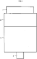
- FIG. 1 is a side view for illustrating an electric drive device according to a first embodiment, which is not part of the present invention.
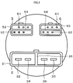
- FIG. 2 is a plan view for illustrating the electric drive device of FIG. 1 .
- the electric drive device according to the first embodiment includes a motor 1, an electronic control unit (ECU) 2, a power supply connector 3, a boss 4, a vehicle signal connector 5, and a torque sensor connector 6.
- the ECU 2 is a controller provided to the motor 1 and configured to control driving of the motor 1.
- the power supply connector 3 is provided to the ECU 2 and electrically connected to the ECU 2.
- the boss 4 is provided to the motor 1.
- the vehicle signal connector 5 is provided to the ECU 2 and electrically connected to the ECU 2.
- the torque sensor connector 6 is provided to the ECU 2 and electrically connected to the ECU 2.
- the ECU 2 is arranged at one axial end portion of the motor 1.
- the boss 4 is provided at another axial end portion of the motor 1.
- the power supply connector 3, the vehicle signal connector 5, and the torque sensor connector 6 are arranged so that the ECU 2 is arranged between the motor 1 and each of the power supply connector 3, the vehicle signal connector 5, and the torque sensor connector 6.
- the stator includes a first coil and a second coil, which are mounted thereto and respectively form a first electric circuit and a second electric circuit independent of each other.
- the rotor is supported by two bearings, and includes magnets.
- the boss 4 is fixed to a distal end portion of the rotor. The boss 4 transmits torque to a gear.
- the ECU 2 is configured to control driving of the motor 1.
- the ECU 2 includes a control circuit, and a first inverter and a second inverter that are independent of each other.
- the first inverter is electrically connected to the first coil.
- the second inverter is electrically connected to the second coil.
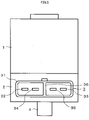
- the power supply connector 3 includes a power supply connector housing 31, a first power supply terminal 32, a second power supply terminal 33, a first ground terminal 34, and a second ground terminal 35.
- the first power supply terminal 32 and the second power supply terminal 33 are provided in the power supply connector housing 31, and electrically connected to separate external power sources, respectively.
- the first ground terminal 34 and the second ground terminal 35 are provided in the power supply connector housing 31, and electrically connected to an external ground.
- the power supply connector 3 further includes a power supply connector partition wall 36 formed on the power supply connector housing 31 and configured to isolate the first power supply terminal 32 and the first ground terminal 34 from the second power supply terminal 33 and the second ground terminal 35.
- the first ground terminal 34 and the second ground terminal 35 are arranged adjacent to each other through intermediation of the power supply connector partition wall 36.
- the first power supply terminal 32, the second power supply terminal 33, the first ground terminal 34, and the second ground terminal 35 arrayed in one direction in the order of the first power supply terminal 32, the first ground terminal 34, the second ground terminal 35, and the second power supply terminal 33 when seen in an axis line direction of the motor 1.
- the power supply connector partition wall 36 prevents occurrence of a short circuit when a conductive substance such as water permeates into the power supply connector housing 31. Specifically, for example, when the conductive substance permeates into a region of the power supply connector housing 31 in which the first power supply terminal 32 and the first ground terminal 34 are arranged, the conductive substance having permeated is prevented from permeating into a region of the power supply connector housing 31 in which the second power supply terminal 33 and the second ground terminal 35 are arranged. With this, occurrence of a short circuit between the second power supply terminal 33 and the second ground terminal 35 is prevented.
- the conductive substance permeates into the region of the power supply connector housing 31 in which the second power supply terminal 33 and the second ground terminal 35 are arranged, the conductive substance having permeated is prevented from permeating into the region of the power supply connector housing 31 in which the first power supply terminal 32 and the first ground terminal 34 are arranged. With this, occurrence of a short circuit between the first power supply terminal 32 and the first ground terminal 34 is prevented.
- the power supply connector partition wall 36 may also be provided between the first power supply terminal 32 and the first ground terminal 34.
- the power supply connector partition wall 36 may also be provided between the second power supply terminal 33 and the second ground terminal 35.
- a signal emitted from a vehicle-side device being a vehicle signal emitting device is transmitted to the vehicle signal connector 5 via, for example, a controller area network (CAN) .
- the vehicle signal connector 5 includes a first vehicle signal terminal 51 and a second vehicle signal terminal 52 that are electrically connected to separate vehicle-side devices, respectively.
- the vehicle signal connector 5 includes three first vehicle signal terminals 51 and three second vehicle signal terminals 52.
- the three first vehicle signal terminals 51 are arrayed in one direction when seen in the axis line direction of the motor 1.
- the three second vehicle signal terminals 52 are arrayed in one direction when seen in the axis line direction of the motor 1.
- the vehicle signal connector 5 further includes a vehicle signal connector housing 53 and a vehicle signal connector partition wall 54.
- the vehicle signal connector housing 53 there are provided the first vehicle signal terminals 51 and the second vehicle signal terminals 52.
- the vehicle signal connector partition wall 54 is formed on the vehicle signal connector housing 53, and is configured to isolate the first vehicle signal terminals 51 and the second vehicle signal terminals 52 from each other.
- the torque sensor connector 6 includes a first torque sensor signal terminal 61 and a second torque sensor signal terminal 62 that are electrically connected to separate torque sensors, respectively.
- the torque sensor connector 6 includes three first torque sensor signal terminals 61 and three second torque sensor signal terminals 62.
- the three first torque sensor signal terminals 61 are arrayed in one direction when seen in the axis line direction of the motor 1.
- the three second torque sensor signal terminals 62 are arrayed in one direction when seen in the axis line direction of the motor 1.
- the torque sensor connector 6 further includes a torque sensor connector housing 63 and a torque sensor connector partition wall 64.
- the torque sensor connector housing 63 In the torque sensor connector housing 63, the there are provided first torque sensor signal terminals 61 and the second torque sensor signal terminals 62.
- the torque sensor connector partition wall 64 is formed on the torque sensor connector housing 63, and is configured to isolate the first torque sensor signal terminals 61 and the second torque sensor signal terminals 62 from each other.
- the electric drive device includes the motor 1, the ECU 2 configured to control driving of the motor 1, and the power supply connector 3 electrically connected to the ECU 2.
- the power supply connector 3 includes the power supply connector housing 31, and the first power supply terminal 32 and the second power supply terminal 33 that are provided in the power supply connector housing 31 and electrically connected to separate external power sources, respectively. Therefore, redundant supply of power from outside can be achieved, and downsizing of the electric drive device can be achieved. Further, it is only required that one connector be mounted to the power supply connector 3 at the time of assembly, and hence reduction in the number of assembly steps can be achieved.
- the power supply connector 3 includes the power supply connector partition wall 36 formed on the power supply connector housing 31 and configured to isolate the first power supply terminal 32 and the second power supply terminal 33 from each other.
- the conductive substance such as water permeates into a region of the power supply connector housing 31 in which any one of the first power supply terminal 32 and the second power supply terminal 33 is arranged
- the conductive substance having permeated is prevented from permeating into a region of the power supply connector housing 31 in which another of the first power supply terminal 32 and the second power supply terminal 33 is arranged.
- occurrence of a short circuit in the another of the first power supply terminal 32 and the second power supply terminal 33 is prevented.
- enhancement of reliability of the electric drive device can be achieved.
- the power supply connector 3 includes the first ground terminal 34 and the second ground terminal 35 that are provided in the power supply connector housing 31 and electrically connected to the external ground, and the first ground terminal 34 and the second ground terminal 35 are arranged adjacent to each other .
- electrical connection of a portion in the ECU 2 with each of the first ground terminal 34 and the second ground terminal 35 can be established in a short distance.
- the electric drive device includes the vehicle signal connector 5 electrically connected to the ECU 2, and the torque sensor connector 6 electrically connected to the ECU 2.
- the vehicle signal connector 5 includes the first vehicle signal terminals 51 and the second vehicle signal terminals 52 electrically connected to separate vehicle-side devices, respectively.
- the torque sensor connector 6 includes the first torque sensor signal terminals 61 and the second torque sensor signal terminals 62 electrically connected to separate torque sensors, respectively. Therefore, redundancy of a vehicle signal and a torque sensor signal can be achieved. As a result, reliability of the electric drive device can be enhanced.
- the vehicle signal connector 5 includes the vehicle signal connector housing 53 in which the first vehicle signal terminals 51 and the second vehicle signal terminals 52 are provided.
- the torque sensor connector 6 includes the torque sensor connector housing 63 in which the first torque sensor signal terminals 61 and the second torque sensor signal terminals 62 are provided. Therefore, redundancy of the vehicle signal and the torque sensor signal can be achieved, and downsizing of the electric drive device can be achieved. Further, it is only required that one connector be mounted to the vehicle signal connector 5 and one connector be mounted to the torque sensor connector 6 at the time of assembly, and hence reduction in the number of assembly steps can be achieved.
- the vehicle signal connector 5 includes the vehicle signal connector partition wall 54 formed on the vehicle signal connector housing 53 and configured to isolate the first vehicle signal terminals 51 and the second vehicle signal terminals 52 from each other.
- the torque sensor connector 6 includes the torque sensor connector partition wall 64 formed on the torque sensor connector housing 63 and configured to isolate the first torque sensor signal terminals 61 and the second torque sensor signal terminals 62 from each other. Therefore, when the conductive substance such as water permeates into a region of the vehicle signal connector housing 53 in which any one of the first vehicle signal terminals 51 and the second vehicle signal terminals 52 are arranged, the conductive substance having permeated is prevented from permeating into a region of the vehicle signal connector housing 53 in which another of the first vehicle signal terminals 51 and the second vehicle signal terminals 52 are arranged.
- the conductive substance permeates into a region of the torque sensor connector housing 63 in which any one of the first torque sensor signal terminals 61 and the second torque sensor signal terminals 62 are arranged, the conductive substance having permeated is prevented from permeating into a region of the torque sensor connector housing 63 in which another of the first torque sensor signal terminals 61 and the second torque sensor signal terminals 62 are arranged.
- occurrence of a short circuit in the another of the first vehicle signal terminals 51 and the second vehicle signal terminals 52 is prevented, and occurrence of a short circuit in the another of the first torque sensor signal terminals 61 and the second torque sensor signal terminals 62 is prevented.
- driving of the electric drive device can be performed, and reliability of the electric drive device can be enhanced.
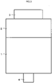
- FIG. 3 is a side view for illustrating an electric drive device according to a second embodiment.
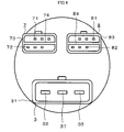
- FIG. 4 is a plan view for illustrating the electric drive device of FIG. 3 .
- the configurations of the motor 1 and the ECU 2 are the same as those of the first embodiment.
- the power supply connector 3 includes the power supply connector housing 31, the first power supply terminal 32, the second power supply terminal 33, and a common ground terminal 37.
- the first power supply terminal 32 and the second power supply terminal 33 are provided in the power supply connector housing 31, and are electrically connected to separate external power sources, respectively.
- the common ground terminal 37 is provided in the power supply connector housing 31, and is electrically connected to the external ground.
- the power supply connector 3 in the second embodiment does not include the power supply connector partition wall 36.
- the electric drive device further includes a first connector 7 and a second connector 8 electrically connected to the ECU 2.
- the first connector 7 and the second connector 8 are each a connector for both a vehicle signal and a torque sensor signal.
- the first connector 7 includes first vehicle signal terminals 71, first torque sensor signal terminals 72, a first connector housing 73, and a first connector partition wall 74.
- the first vehicle signal terminals 71 are electrically connected to a first vehicle-side device being a first vehicle signal emitting device.
- the first torque sensor signal terminals 72 are electrically connected to a first torque sensor.
- the first connector housing 73 there are provided the first vehicle signal terminals 71 and the first torque sensor signal terminals 72.
- the first connector partition wall 74 is formed on the first connector housing 73, and is configured to isolate the first vehicle signal terminals 71 and the first torque sensor signal terminals 72 from each other.
- the second connector 8 includes second vehicle signal terminals 81, second torque sensor signal terminals 82, a second connector housing 83, and a second connector partition wall 84.
- the second vehicle signal terminals 81 are electrically connected to a second vehicle-side device being a second vehicle signal emitting device.
- the second torque sensor signal terminals 82 are electrically connected to a second torque sensor.
- In the second connector housing 83 there are provided the second vehicle signal terminals 81 and the second torque sensor signal terminals 82.
- the second connector partition wall 84 is formed on the second connector housing 83, and is configured to isolate the second vehicle signal terminals 81 and the second torque sensor signal terminals 82 from each other.
- the first vehicle-side device and the second vehicle-side device are separate vehicle-side devices.
- the first torque sensor and the second torque sensor are separate torque sensors .
- Other configurations are the same as those of the first embodiment.
- the power supply connector 3 includes the common ground terminal 37 provided in the power supply connector housing 31 and electrically connected to the external ground.
- the number of terminals of the power supply connector 3 can be reduced.
- downsizing of the electric drive device can be achieved, and reduction in cost of the electric drive device can be achieved owing to reduction in the number of components .
- the electric drive device includes the first connector 7 and the second connector 8 electrically connected to the ECU 2.
- the first connector 7 includes the first vehicle signal terminals 71 electrically connected to the first vehicle-side device, the first torque sensor signal terminals 72 electrically connected to the first torque sensor, and the first connector housing 73 in which the first vehicle signal terminals 71 and the first torque sensor signal terminals 72 are provided.
- the second connector 8 includes the second vehicle signal terminals 81 electrically connected to the second vehicle-side device, the second torque sensor signal terminals 82 electrically connected to the second torque sensor, and the second connector housing 83 in which the second vehicle signal terminals 81 and the second torque sensor signal terminals 82 are provided.
- the power supply connector housing 31 includes the common ground terminal 37 that is provided in the power supply connector housing 31 and electrically connected to the external ground.
- the electric drive device includes the first connector 7 and the second connector 8 electrically connected to the ECU 2.
- the electric drive device includes the power supply connector 3 electrically connected to the ECU 2, and the vehicle signal connector 5 electrically connected to the ECU 2.
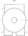
- FIG. 5 is a side view for illustrating an electric drive device according to a third embodiment, which is not part of the present invention.
- FIG. 6 is a bottom view for illustrating the electric drive device of FIG. 5 .
- FIG. 7 is a side view for illustrating the electric drive device of FIG. 6 .
- the ECU 2 is arranged between the motor 1 and the boss 4.
- the power supply connector 3 is arranged on a side surface of the ECU 2.
- the vehicle signal connector 5 and the torque sensor connector 6 are arranged on a side surface of the ECU 2.
- Other configurations are the same as those of the first embodiment.
- the power supply connector 3, the vehicle signal connector 5, and the torque sensor connector 6 are arranged on the side surfaces of the ECU 2. Therefore, as compared to the first embodiment, a dimension of the electric drive device in the axis line direction of the motor 1 can be reduced.
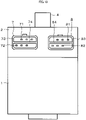
- FIG. 8 is a side view for illustrating an electric drive device according to a fourth embodiment, which is in accordance with the present invention.
- FIG. 9 is a bottom view for illustrating the electric drive device of FIG. 8 .
- FIG. 10 is a side view for illustrating the electric drive device of FIG. 9 .
- the ECU 2 is arranged between the motor 1 and the boss 4.
- the power supply connector 3 is arranged on a side surface of the ECU 2.
- the first connector 7 and the second connector 8 are arranged on a side surface of the ECU 2.
- Other configurations are the same as those of the second embodiment.
- the power supply connector 3, the first connector 7, and the second connector 8 are arranged on the side surfaces of the ECU 2. Therefore, as compared to the second embodiment, a dimension of the electric drive device in the axis line direction of the motor 1 can be reduced.
Landscapes
- Engineering & Computer Science (AREA)
- Power Engineering (AREA)
- Microelectronics & Electronic Packaging (AREA)
- Motor Or Generator Frames (AREA)
- Electric Propulsion And Braking For Vehicles (AREA)
- Connector Housings Or Holding Contact Members (AREA)
Claims (6)
- Elektrische Antriebseinrichtung für eine elektrische Servolenkeinrichtung, aufweisend:einen Motor (1);eine Steuerung (2), die elektrisch mit dem Motor (1) verbunden ist, wobei die Steuerung dazu eingerichtet ist, den Antrieb des Motors (1) zu steuern und einen ersten Inverter und einen zweiten Inverter aufweist, die unabhängig voneinander sind; undeinen Stromversorgungsverbinder (3), der elektrisch mit der Steuerung (2) verbunden ist,wobei der Stromversorgungsverbinder (3) aufweist:ein Stromversorgungsverbinder-Gehäuse (31);einen ersten Stromversorgungsanschluss (32) und einen zweiten Stromversorgungsanschluss (33), die jeweils dazu eingerichtet sind, elektrisch mit unterschiedlichen externen Stromquellen verbunden zu werden,dadurch gekennzeichnet, dassder erste Stromversorgungsanschluss (32) und der zweite Stromversorgungsanschluss (33) in dem Stromversorgungsverbinder-Gehäuse (31) vorgesehen sind, und wobei die elektrische Antriebseinrichtung ferner aufweisteinen gemeinsamen Erdungsanschluss (37), der in dem Stromversorgungsverbinder-Gehäuse (31) vorgesehen ist und dazu eingerichtet ist, elektrisch mit einer externen Masse verbunden zu werden.
- Elektrische Antriebseinrichtung nach Anspruch 1, wobei der Stromversorgungsverbinder (3) ferner eine Stromversorgungsverbinder-Trennwand (36) aufweist, die an dem Stromversorgungsverbinder-Gehäuse (31) ausgebildet ist und dazu eingerichtet ist, den ersten Stromversorgungsanschluss (32) und den zweiten Stromversorgungsanschluss (33) voneinander zu isolieren.
- Elektrische Antriebseinrichtung nach Anspruch 1 oder 2, ferner aufweisend:einen Fahrzeugsignalverbinder (5), der elektrisch mit der Steuerung (2) verbunden ist; undeinen Drehmomentsensorverbinder (6), der elektrisch mit der Steuerung (2) verbunden ist,wobei der Fahrzeugsignalverbinder (5) einen ersten Fahrzeugsignalanschluss (51) und einen zweiten Fahrzeugsignalanschluss (52) aufweist, die jeweils elektrisch mit separaten Fahrzeugsignal-abgebenden Einrichtungen verbunden sind, undwobei der Drehmomentsensorverbinder (6) einen ersten Drehmomentsensorsignalanschluss (61) und einen zweiten Drehmomentsensorsignalanschluss (62) aufweist, die jeweils elektrisch mit separaten Drehmomentsensoren verbunden sind.
- Elektrische Antriebseinrichtung nach Anspruch 3,wobei der Fahrzeugsignalanschluss (5) ferner ein Fahrzeugsignalverbinder-Gehäuse (53) aufweist, in dem der erste Fahrzeugsignalanschluss (51) und der zweite Fahrzeugsignalanschluss (52) vorgesehen sind, undwobei der Drehmomentsensorverbinder (6) ferner ein Drehmomentsensorverbinder-Gehäuse (63) aufweist, in dem der erste Drehmomentsensorsignalanschluss (61) und der zweite Drehmomentsensorsignalanschluss (62) vorgesehen sind.
- Elektrische Antriebseinrichtung nach Anspruch 4,wobei der Fahrzeugsignalverbinder (5) ferner eine Fahrzeugsignalverbinder-Trennwand (54) aufweist, die an dem Fahrzeugsignalverbinder-Gehäuse (53) ausgebildet ist und dazu eingerichtet ist, den ersten Fahrzeugsignalanschluss (51) und den zweiten Fahrzeugsignalanschluss (52) voneinander zu isolieren, undwobei der Drehmomentsensorverbinder (6) ferner eine Drehmomentsensorverbinder-Trennwand (64) aufweist, die an dem Drehmomentsensorverbinder-Gehäuse (63) ausgebildet ist und dazu eingerichtet ist, den ersten Drehmomentsensorsignalanschluss (61) und den zweiten Drehmomentsensorsignalanschluss (62) voneinander zu isolieren.
- Elektrische Antriebseinrichtung nach Anspruch 1 oder 2, ferner aufweisend einen ersten Verbinder (7) und einen zweiten Verbinder (8), die elektrisch mit der Steuerung (2) verbunden sind,wobei der erste Verbinder (7) aufweist:einen ersten Fahrzeugsignalanschluss (71), der elektrisch mit einer ersten Fahrzeugsignal-abgebenden Einrichtung verbunden ist;einen ersten Drehmomentsensoranschluss (72), der elektrisch mit einem ersten Drehmomentsensor verbunden ist; undein erstes Verbindergehäuse (73), in dem der erste Fahrzeugsignalanschluss (71) und der erste Drehmomentsensorsignalanschluss (72) vorgesehen sind, undwobei der zweite Verbinder (8) aufweist:einen zweiten Fahrzeugsignalanschluss (81), der elektrisch mit einer zweiten Fahrzeugsignal-abgebenden Einrichtung verbunden ist;einen zweiten Drehmomentsensorsignalanschluss (82), der elektrisch mit einem zweiten Drehmomentsensor verbunden ist; undein zweites Verbindergehäuse (83), in dem der zweite Fahrzeugsignalanschluss (81) und der zweite Drehmomentsensorsignalanschluss (82) vorgesehen sind.
Applications Claiming Priority (1)
| Application Number | Priority Date | Filing Date | Title |
|---|---|---|---|
| PCT/JP2016/072979 WO2018025378A1 (ja) | 2016-08-04 | 2016-08-04 | 電動駆動装置 |
Publications (3)
| Publication Number | Publication Date |
|---|---|
| EP3496241A1 EP3496241A1 (de) | 2019-06-12 |
| EP3496241A4 EP3496241A4 (de) | 2019-09-11 |
| EP3496241B1 true EP3496241B1 (de) | 2022-07-06 |
Family
ID=61072718
Family Applications (1)
| Application Number | Title | Priority Date | Filing Date |
|---|---|---|---|
| EP16911637.3A Active EP3496241B1 (de) | 2016-08-04 | 2016-08-04 | Elektrische antriebsvorrichtung |
Country Status (5)
| Country | Link |
|---|---|
| US (1) | US10985628B2 (de) |
| EP (1) | EP3496241B1 (de) |
| JP (1) | JP6727304B2 (de) |
| CN (1) | CN109565211B (de) |
| WO (1) | WO2018025378A1 (de) |
Families Citing this family (1)
| Publication number | Priority date | Publication date | Assignee | Title |
|---|---|---|---|---|
| WO2024057683A1 (ja) * | 2022-09-14 | 2024-03-21 | 日立Astemo株式会社 | 電動駆動装置及び電動パワーステアリング装置 |
Family Cites Families (21)
| Publication number | Priority date | Publication date | Assignee | Title |
|---|---|---|---|---|
| JP2573753B2 (ja) * | 1991-04-01 | 1997-01-22 | 矢崎総業株式会社 | コネクタ |
| JP2998885B2 (ja) * | 1994-07-11 | 2000-01-17 | 矢崎総業株式会社 | コネクタのスペーサ検知構造 |
| JP3563835B2 (ja) * | 1995-07-12 | 2004-09-08 | 光洋精工株式会社 | パワーステアリング装置 |
| JPH09245891A (ja) * | 1996-03-13 | 1997-09-19 | Sumitomo Wiring Syst Ltd | コネクタ |
| US6923288B2 (en) * | 2000-04-03 | 2005-08-02 | Trw Inc. | Electric steering apparatus |
| JP3624802B2 (ja) * | 2000-06-30 | 2005-03-02 | 株式会社村田製作所 | 非可逆回路素子、およびその実装構造 |
| JP3774624B2 (ja) * | 2000-10-18 | 2006-05-17 | 三菱電機株式会社 | 電動パワーステアリング装置 |
| JP4368237B2 (ja) | 2004-04-28 | 2009-11-18 | パナソニック株式会社 | 電気コネクタ |
| US7731511B2 (en) * | 2007-07-17 | 2010-06-08 | Tyco Electronics Corporation | Panel mounted power module |
| CN201266737Y (zh) * | 2008-05-28 | 2009-07-01 | 富士康(昆山)电脑接插件有限公司 | 电连接器 |
| JP5192417B2 (ja) * | 2009-02-24 | 2013-05-08 | 株式会社デンソー | 燃料供給装置 |
| US8888509B2 (en) * | 2012-07-13 | 2014-11-18 | Allied Motion Technologies Inc. | Electrical connector and method of assembling same |
| US9729028B2 (en) | 2012-10-04 | 2017-08-08 | Mitsubishi Electric Corporation | Rotary electric machine having integrated drive control device |
| WO2014064856A1 (ja) | 2012-10-23 | 2014-05-01 | 日本精工株式会社 | トルク検出装置、電動パワーステアリング装置及び車両 |
| JP5898104B2 (ja) * | 2013-02-13 | 2016-04-06 | 日立オートモティブシステムズステアリング株式会社 | 電源電圧監視回路、車両のセンサ回路およびパワーステアリング装置 |
| US9184640B2 (en) * | 2013-04-05 | 2015-11-10 | Nsk Ltd. | Motor controller and production method of the same |
| EP3053780B1 (de) * | 2013-10-04 | 2021-08-25 | Mitsubishi Electric Corporation | Elektronische steuerungsvorrichtung und verfahren zur herstellung davon sowie elektrische servolenkvorrichtung |
| JP2016032977A (ja) | 2014-07-31 | 2016-03-10 | 株式会社デンソー | 電動パワーステアリングシステムおよび車両制御システム |
| JP6277928B2 (ja) * | 2014-09-30 | 2018-02-14 | 株式会社オートネットワーク技術研究所 | 自動車用制御システム |
| US10167012B2 (en) * | 2014-10-22 | 2019-01-01 | Mitsubishi Electric Corporation | Electric power steering device |
| CN107735307B (zh) * | 2015-07-08 | 2020-07-24 | 蒂森克虏伯普利斯坦股份公司 | 在电力供应中双重使用的电感器芯 |
-
2016
- 2016-08-04 CN CN201680088109.2A patent/CN109565211B/zh active Active
- 2016-08-04 EP EP16911637.3A patent/EP3496241B1/de active Active
- 2016-08-04 JP JP2018531690A patent/JP6727304B2/ja active Active
- 2016-08-04 US US16/319,646 patent/US10985628B2/en active Active
- 2016-08-04 WO PCT/JP2016/072979 patent/WO2018025378A1/ja active Application Filing
Also Published As
| Publication number | Publication date |
|---|---|
| EP3496241A1 (de) | 2019-06-12 |
| JP6727304B2 (ja) | 2020-07-22 |
| US20200220423A1 (en) | 2020-07-09 |
| US10985628B2 (en) | 2021-04-20 |
| CN109565211A (zh) | 2019-04-02 |
| EP3496241A4 (de) | 2019-09-11 |
| JPWO2018025378A1 (ja) | 2018-11-01 |
| CN109565211B (zh) | 2021-01-05 |
| WO2018025378A1 (ja) | 2018-02-08 |
Similar Documents
| Publication | Publication Date | Title |
|---|---|---|
| CN105792577B (zh) | 驱动装置 | |
| US10906577B2 (en) | Electric power steering apparatus | |
| US20200127524A1 (en) | Busbar, motor, and power transmission system using same | |
| JP7067339B2 (ja) | 駆動装置、および、これを用いた電動パワーステアリング装置 | |
| JP2016032977A (ja) | 電動パワーステアリングシステムおよび車両制御システム | |
| US20200212767A1 (en) | Electric Drive Device and Electric Power Steering Apparatus | |
| WO2016174704A1 (ja) | 制御装置 | |
| US11932324B2 (en) | Electric drive device of electric power steering apparatus | |
| WO2018225123A1 (ja) | 駆動装置一体型回転電機、及びそれを用いた電動パワーステアリング装置 | |
| JP7294252B2 (ja) | 駆動装置 | |
| US9293970B2 (en) | Control device and motor unit including the control device | |
| US10834856B2 (en) | Electronic control unit | |
| EP3496241B1 (de) | Elektrische antriebsvorrichtung | |
| CN113169472B (zh) | 电子控制装置和电动动力转向装置 | |
| JP7122180B2 (ja) | 電動駆動装置、及び電動パワーステアリング装置 | |
| CN114132375A (zh) | 电动转向助力系统及其助力装置 | |
| JP7432706B2 (ja) | 自動車のワイパーシステム用のブラシレス直流電気モータ | |
| US20190036425A1 (en) | Electromechanical Actuator Comprising a Redundant Electronic Sub-System | |
| CN114466781B (zh) | 电子控制装置 | |
| WO2023199463A1 (ja) | 駆動装置 | |
| JP2008296854A (ja) | 電動パワーステアリング装置のecu接地構造 | |
| JP2022144150A (ja) | 駆動装置 | |
| WO2021100075A1 (ja) | 回転電機装置および電動パワーステアリング装置 | |
| JP2022026387A (ja) | モータ制御装置、および電動パワーステアリング装置 | |
| JP2023042465A (ja) | 駆動装置 |
Legal Events
| Date | Code | Title | Description |
|---|---|---|---|
| STAA | Information on the status of an ep patent application or granted ep patent |
Free format text: STATUS: THE INTERNATIONAL PUBLICATION HAS BEEN MADE |
|
| PUAI | Public reference made under article 153(3) epc to a published international application that has entered the european phase |
Free format text: ORIGINAL CODE: 0009012 |
|
| STAA | Information on the status of an ep patent application or granted ep patent |
Free format text: STATUS: REQUEST FOR EXAMINATION WAS MADE |
|
| 17P | Request for examination filed |
Effective date: 20190108 |
|
| AK | Designated contracting states |
Kind code of ref document: A1 Designated state(s): AL AT BE BG CH CY CZ DE DK EE ES FI FR GB GR HR HU IE IS IT LI LT LU LV MC MK MT NL NO PL PT RO RS SE SI SK SM TR |
|
| AX | Request for extension of the european patent |
Extension state: BA ME |
|
| A4 | Supplementary search report drawn up and despatched |
Effective date: 20190814 |
|
| RIC1 | Information provided on ipc code assigned before grant |
Ipc: H02K 5/22 20060101AFI20190808BHEP Ipc: H02P 29/028 20160101ALN20190808BHEP Ipc: B62D 5/04 20060101ALN20190808BHEP |
|
| DAV | Request for validation of the european patent (deleted) | ||
| DAX | Request for extension of the european patent (deleted) | ||
| STAA | Information on the status of an ep patent application or granted ep patent |
Free format text: STATUS: EXAMINATION IS IN PROGRESS |
|
| 17Q | First examination report despatched |
Effective date: 20200203 |
|
| RIC1 | Information provided on ipc code assigned before grant |
Ipc: B62D 5/04 20060101ALN20200805BHEP Ipc: H02P 29/028 20160101ALN20200805BHEP Ipc: H02K 5/22 20060101AFI20200805BHEP |
|
| STAA | Information on the status of an ep patent application or granted ep patent |
Free format text: STATUS: EXAMINATION IS IN PROGRESS |
|
| STAA | Information on the status of an ep patent application or granted ep patent |
Free format text: STATUS: EXAMINATION IS IN PROGRESS |
|
| RIC1 | Information provided on ipc code assigned before grant |
Ipc: H02P 29/028 20160101ALN20220218BHEP Ipc: B62D 5/04 20060101ALN20220218BHEP Ipc: H02K 5/22 20060101AFI20220218BHEP |
|
| RIC1 | Information provided on ipc code assigned before grant |
Ipc: H02P 29/028 20160101ALN20220314BHEP Ipc: B62D 5/04 20060101ALN20220314BHEP Ipc: H02K 5/22 20060101AFI20220314BHEP |
|
| GRAP | Despatch of communication of intention to grant a patent |
Free format text: ORIGINAL CODE: EPIDOSNIGR1 |
|
| STAA | Information on the status of an ep patent application or granted ep patent |
Free format text: STATUS: GRANT OF PATENT IS INTENDED |
|
| RIC1 | Information provided on ipc code assigned before grant |
Ipc: H02P 29/028 20160101ALN20220328BHEP Ipc: B62D 5/04 20060101ALN20220328BHEP Ipc: H02K 5/22 20060101AFI20220328BHEP |
|
| INTG | Intention to grant announced |
Effective date: 20220425 |
|
| GRAS | Grant fee paid |
Free format text: ORIGINAL CODE: EPIDOSNIGR3 |
|
| GRAA | (expected) grant |
Free format text: ORIGINAL CODE: 0009210 |
|
| STAA | Information on the status of an ep patent application or granted ep patent |
Free format text: STATUS: THE PATENT HAS BEEN GRANTED |
|
| AK | Designated contracting states |
Kind code of ref document: B1 Designated state(s): AL AT BE BG CH CY CZ DE DK EE ES FI FR GB GR HR HU IE IS IT LI LT LU LV MC MK MT NL NO PL PT RO RS SE SI SK SM TR |
|
| REG | Reference to a national code |
Ref country code: AT Ref legal event code: REF Ref document number: 1503584 Country of ref document: AT Kind code of ref document: T Effective date: 20220715 Ref country code: CH Ref legal event code: EP |
|
| REG | Reference to a national code |
Ref country code: DE Ref legal event code: R096 Ref document number: 602016073435 Country of ref document: DE |
|
| REG | Reference to a national code |
Ref country code: IE Ref legal event code: FG4D |
|
| REG | Reference to a national code |
Ref country code: LT Ref legal event code: MG9D |
|
| REG | Reference to a national code |
Ref country code: NL Ref legal event code: MP Effective date: 20220706 |
|
| PG25 | Lapsed in a contracting state [announced via postgrant information from national office to epo] |
Ref country code: SE Free format text: LAPSE BECAUSE OF FAILURE TO SUBMIT A TRANSLATION OF THE DESCRIPTION OR TO PAY THE FEE WITHIN THE PRESCRIBED TIME-LIMIT Effective date: 20220706 Ref country code: RS Free format text: LAPSE BECAUSE OF FAILURE TO SUBMIT A TRANSLATION OF THE DESCRIPTION OR TO PAY THE FEE WITHIN THE PRESCRIBED TIME-LIMIT Effective date: 20220706 Ref country code: PT Free format text: LAPSE BECAUSE OF FAILURE TO SUBMIT A TRANSLATION OF THE DESCRIPTION OR TO PAY THE FEE WITHIN THE PRESCRIBED TIME-LIMIT Effective date: 20221107 Ref country code: NO Free format text: LAPSE BECAUSE OF FAILURE TO SUBMIT A TRANSLATION OF THE DESCRIPTION OR TO PAY THE FEE WITHIN THE PRESCRIBED TIME-LIMIT Effective date: 20221006 Ref country code: NL Free format text: LAPSE BECAUSE OF FAILURE TO SUBMIT A TRANSLATION OF THE DESCRIPTION OR TO PAY THE FEE WITHIN THE PRESCRIBED TIME-LIMIT Effective date: 20220706 Ref country code: LV Free format text: LAPSE BECAUSE OF FAILURE TO SUBMIT A TRANSLATION OF THE DESCRIPTION OR TO PAY THE FEE WITHIN THE PRESCRIBED TIME-LIMIT Effective date: 20220706 Ref country code: LT Free format text: LAPSE BECAUSE OF FAILURE TO SUBMIT A TRANSLATION OF THE DESCRIPTION OR TO PAY THE FEE WITHIN THE PRESCRIBED TIME-LIMIT Effective date: 20220706 Ref country code: FI Free format text: LAPSE BECAUSE OF FAILURE TO SUBMIT A TRANSLATION OF THE DESCRIPTION OR TO PAY THE FEE WITHIN THE PRESCRIBED TIME-LIMIT Effective date: 20220706 Ref country code: ES Free format text: LAPSE BECAUSE OF FAILURE TO SUBMIT A TRANSLATION OF THE DESCRIPTION OR TO PAY THE FEE WITHIN THE PRESCRIBED TIME-LIMIT Effective date: 20220706 |
|
| REG | Reference to a national code |
Ref country code: AT Ref legal event code: MK05 Ref document number: 1503584 Country of ref document: AT Kind code of ref document: T Effective date: 20220706 |
|
| PG25 | Lapsed in a contracting state [announced via postgrant information from national office to epo] |
Ref country code: PL Free format text: LAPSE BECAUSE OF FAILURE TO SUBMIT A TRANSLATION OF THE DESCRIPTION OR TO PAY THE FEE WITHIN THE PRESCRIBED TIME-LIMIT Effective date: 20220706 Ref country code: IS Free format text: LAPSE BECAUSE OF FAILURE TO SUBMIT A TRANSLATION OF THE DESCRIPTION OR TO PAY THE FEE WITHIN THE PRESCRIBED TIME-LIMIT Effective date: 20221106 Ref country code: HR Free format text: LAPSE BECAUSE OF FAILURE TO SUBMIT A TRANSLATION OF THE DESCRIPTION OR TO PAY THE FEE WITHIN THE PRESCRIBED TIME-LIMIT Effective date: 20220706 Ref country code: GR Free format text: LAPSE BECAUSE OF FAILURE TO SUBMIT A TRANSLATION OF THE DESCRIPTION OR TO PAY THE FEE WITHIN THE PRESCRIBED TIME-LIMIT Effective date: 20221007 |
|
| REG | Reference to a national code |
Ref country code: CH Ref legal event code: PL |
|
| REG | Reference to a national code |
Ref country code: DE Ref legal event code: R097 Ref document number: 602016073435 Country of ref document: DE |
|
| PG25 | Lapsed in a contracting state [announced via postgrant information from national office to epo] |
Ref country code: SM Free format text: LAPSE BECAUSE OF FAILURE TO SUBMIT A TRANSLATION OF THE DESCRIPTION OR TO PAY THE FEE WITHIN THE PRESCRIBED TIME-LIMIT Effective date: 20220706 Ref country code: RO Free format text: LAPSE BECAUSE OF FAILURE TO SUBMIT A TRANSLATION OF THE DESCRIPTION OR TO PAY THE FEE WITHIN THE PRESCRIBED TIME-LIMIT Effective date: 20220706 Ref country code: MC Free format text: LAPSE BECAUSE OF FAILURE TO SUBMIT A TRANSLATION OF THE DESCRIPTION OR TO PAY THE FEE WITHIN THE PRESCRIBED TIME-LIMIT Effective date: 20220706 Ref country code: LU Free format text: LAPSE BECAUSE OF NON-PAYMENT OF DUE FEES Effective date: 20220804 Ref country code: LI Free format text: LAPSE BECAUSE OF NON-PAYMENT OF DUE FEES Effective date: 20220831 Ref country code: DK Free format text: LAPSE BECAUSE OF FAILURE TO SUBMIT A TRANSLATION OF THE DESCRIPTION OR TO PAY THE FEE WITHIN THE PRESCRIBED TIME-LIMIT Effective date: 20220706 Ref country code: CZ Free format text: LAPSE BECAUSE OF FAILURE TO SUBMIT A TRANSLATION OF THE DESCRIPTION OR TO PAY THE FEE WITHIN THE PRESCRIBED TIME-LIMIT Effective date: 20220706 Ref country code: CH Free format text: LAPSE BECAUSE OF NON-PAYMENT OF DUE FEES Effective date: 20220831 Ref country code: AT Free format text: LAPSE BECAUSE OF FAILURE TO SUBMIT A TRANSLATION OF THE DESCRIPTION OR TO PAY THE FEE WITHIN THE PRESCRIBED TIME-LIMIT Effective date: 20220706 |
|
| REG | Reference to a national code |
Ref country code: BE Ref legal event code: MM Effective date: 20220831 |
|
| PLBE | No opposition filed within time limit |
Free format text: ORIGINAL CODE: 0009261 |
|
| STAA | Information on the status of an ep patent application or granted ep patent |
Free format text: STATUS: NO OPPOSITION FILED WITHIN TIME LIMIT |
|
| PG25 | Lapsed in a contracting state [announced via postgrant information from national office to epo] |
Ref country code: SK Free format text: LAPSE BECAUSE OF FAILURE TO SUBMIT A TRANSLATION OF THE DESCRIPTION OR TO PAY THE FEE WITHIN THE PRESCRIBED TIME-LIMIT Effective date: 20220706 Ref country code: EE Free format text: LAPSE BECAUSE OF FAILURE TO SUBMIT A TRANSLATION OF THE DESCRIPTION OR TO PAY THE FEE WITHIN THE PRESCRIBED TIME-LIMIT Effective date: 20220706 |
|
| 26N | No opposition filed |
Effective date: 20230411 |
|
| P01 | Opt-out of the competence of the unified patent court (upc) registered |
Effective date: 20230512 |
|
| GBPC | Gb: european patent ceased through non-payment of renewal fee |
Effective date: 20221006 |
|
| PG25 | Lapsed in a contracting state [announced via postgrant information from national office to epo] |
Ref country code: AL Free format text: LAPSE BECAUSE OF FAILURE TO SUBMIT A TRANSLATION OF THE DESCRIPTION OR TO PAY THE FEE WITHIN THE PRESCRIBED TIME-LIMIT Effective date: 20220706 |
|
| PG25 | Lapsed in a contracting state [announced via postgrant information from national office to epo] |
Ref country code: IE Free format text: LAPSE BECAUSE OF NON-PAYMENT OF DUE FEES Effective date: 20220804 |
|
| PG25 | Lapsed in a contracting state [announced via postgrant information from national office to epo] |
Ref country code: SI Free format text: LAPSE BECAUSE OF FAILURE TO SUBMIT A TRANSLATION OF THE DESCRIPTION OR TO PAY THE FEE WITHIN THE PRESCRIBED TIME-LIMIT Effective date: 20220706 |
|
| PG25 | Lapsed in a contracting state [announced via postgrant information from national office to epo] |
Ref country code: BE Free format text: LAPSE BECAUSE OF NON-PAYMENT OF DUE FEES Effective date: 20220831 |
|
| PG25 | Lapsed in a contracting state [announced via postgrant information from national office to epo] |
Ref country code: GB Free format text: LAPSE BECAUSE OF NON-PAYMENT OF DUE FEES Effective date: 20221006 |
|
| PGFP | Annual fee paid to national office [announced via postgrant information from national office to epo] |
Ref country code: FR Payment date: 20230703 Year of fee payment: 8 Ref country code: DE Payment date: 20230627 Year of fee payment: 8 |
|
| PG25 | Lapsed in a contracting state [announced via postgrant information from national office to epo] |
Ref country code: IT Free format text: LAPSE BECAUSE OF FAILURE TO SUBMIT A TRANSLATION OF THE DESCRIPTION OR TO PAY THE FEE WITHIN THE PRESCRIBED TIME-LIMIT Effective date: 20220706 |
|
| PG25 | Lapsed in a contracting state [announced via postgrant information from national office to epo] |
Ref country code: HU Free format text: LAPSE BECAUSE OF FAILURE TO SUBMIT A TRANSLATION OF THE DESCRIPTION OR TO PAY THE FEE WITHIN THE PRESCRIBED TIME-LIMIT; INVALID AB INITIO Effective date: 20160804 |
|
| PG25 | Lapsed in a contracting state [announced via postgrant information from national office to epo] |
Ref country code: MK Free format text: LAPSE BECAUSE OF FAILURE TO SUBMIT A TRANSLATION OF THE DESCRIPTION OR TO PAY THE FEE WITHIN THE PRESCRIBED TIME-LIMIT Effective date: 20220706 Ref country code: CY Free format text: LAPSE BECAUSE OF FAILURE TO SUBMIT A TRANSLATION OF THE DESCRIPTION OR TO PAY THE FEE WITHIN THE PRESCRIBED TIME-LIMIT Effective date: 20220706 |