EP3496187B1 - Elektrodenheizvorrichtung und sekundärbatterieherstellungssystem damit - Google Patents
Elektrodenheizvorrichtung und sekundärbatterieherstellungssystem damit Download PDFInfo
- Publication number
- EP3496187B1 EP3496187B1 EP18846383.0A EP18846383A EP3496187B1 EP 3496187 B1 EP3496187 B1 EP 3496187B1 EP 18846383 A EP18846383 A EP 18846383A EP 3496187 B1 EP3496187 B1 EP 3496187B1
- Authority
- EP
- European Patent Office
- Prior art keywords
- electrode
- heating
- drying space
- drying
- transfer roller
- Prior art date
- Legal status (The legal status is an assumption and is not a legal conclusion. Google has not performed a legal analysis and makes no representation as to the accuracy of the status listed.)
- Active
Links
Images



Classifications
-
- H—ELECTRICITY
- H01—ELECTRIC ELEMENTS
- H01M—PROCESSES OR MEANS, e.g. BATTERIES, FOR THE DIRECT CONVERSION OF CHEMICAL ENERGY INTO ELECTRICAL ENERGY
- H01M4/00—Electrodes
- H01M4/02—Electrodes composed of, or comprising, active material
- H01M4/04—Processes of manufacture in general
- H01M4/0471—Processes of manufacture in general involving thermal treatment, e.g. firing, sintering, backing particulate active material, thermal decomposition, pyrolysis
-
- F—MECHANICAL ENGINEERING; LIGHTING; HEATING; WEAPONS; BLASTING
- F26—DRYING
- F26B—DRYING SOLID MATERIALS OR OBJECTS BY REMOVING LIQUID THEREFROM
- F26B13/00—Machines and apparatus for drying fabrics, fibres, yarns, or other materials in long lengths, with progressive movement
- F26B13/06—Machines and apparatus for drying fabrics, fibres, yarns, or other materials in long lengths, with progressive movement with movement in a sinuous or zig-zag path
-
- F—MECHANICAL ENGINEERING; LIGHTING; HEATING; WEAPONS; BLASTING
- F26—DRYING
- F26B—DRYING SOLID MATERIALS OR OBJECTS BY REMOVING LIQUID THEREFROM
- F26B3/00—Drying solid materials or objects by processes involving the application of heat
- F26B3/28—Drying solid materials or objects by processes involving the application of heat by radiation, e.g. from the sun
-
- F—MECHANICAL ENGINEERING; LIGHTING; HEATING; WEAPONS; BLASTING
- F26—DRYING
- F26B—DRYING SOLID MATERIALS OR OBJECTS BY REMOVING LIQUID THEREFROM
- F26B3/00—Drying solid materials or objects by processes involving the application of heat
- F26B3/28—Drying solid materials or objects by processes involving the application of heat by radiation, e.g. from the sun
- F26B3/30—Drying solid materials or objects by processes involving the application of heat by radiation, e.g. from the sun from infrared-emitting elements
-
- H—ELECTRICITY
- H01—ELECTRIC ELEMENTS
- H01J—ELECTRIC DISCHARGE TUBES OR DISCHARGE LAMPS
- H01J61/00—Gas-discharge or vapour-discharge lamps
- H01J61/02—Details
- H01J61/12—Selection of substances for gas fillings; Specified operating pressure or temperature
- H01J61/16—Selection of substances for gas fillings; Specified operating pressure or temperature having helium, argon, neon, krypton, or xenon as the principle constituent
-
- H—ELECTRICITY
- H01—ELECTRIC ELEMENTS
- H01M—PROCESSES OR MEANS, e.g. BATTERIES, FOR THE DIRECT CONVERSION OF CHEMICAL ENERGY INTO ELECTRICAL ENERGY
- H01M10/00—Secondary cells; Manufacture thereof
- H01M10/04—Construction or manufacture in general
-
- H—ELECTRICITY
- H01—ELECTRIC ELEMENTS
- H01M—PROCESSES OR MEANS, e.g. BATTERIES, FOR THE DIRECT CONVERSION OF CHEMICAL ENERGY INTO ELECTRICAL ENERGY
- H01M10/00—Secondary cells; Manufacture thereof
- H01M10/04—Construction or manufacture in general
- H01M10/0404—Machines for assembling batteries
-
- H—ELECTRICITY
- H01—ELECTRIC ELEMENTS
- H01M—PROCESSES OR MEANS, e.g. BATTERIES, FOR THE DIRECT CONVERSION OF CHEMICAL ENERGY INTO ELECTRICAL ENERGY
- H01M10/00—Secondary cells; Manufacture thereof
- H01M10/04—Construction or manufacture in general
- H01M10/0413—Large-sized flat cells or batteries for motive or stationary systems with plate-like electrodes
-
- H—ELECTRICITY
- H01—ELECTRIC ELEMENTS
- H01M—PROCESSES OR MEANS, e.g. BATTERIES, FOR THE DIRECT CONVERSION OF CHEMICAL ENERGY INTO ELECTRICAL ENERGY
- H01M10/00—Secondary cells; Manufacture thereof
- H01M10/04—Construction or manufacture in general
- H01M10/0436—Small-sized flat cells or batteries for portable equipment
-
- H—ELECTRICITY
- H01—ELECTRIC ELEMENTS
- H01M—PROCESSES OR MEANS, e.g. BATTERIES, FOR THE DIRECT CONVERSION OF CHEMICAL ENERGY INTO ELECTRICAL ENERGY
- H01M4/00—Electrodes
- H01M4/02—Electrodes composed of, or comprising, active material
- H01M4/04—Processes of manufacture in general
-
- H—ELECTRICITY
- H05—ELECTRIC TECHNIQUES NOT OTHERWISE PROVIDED FOR
- H05B—ELECTRIC HEATING; ELECTRIC LIGHT SOURCES NOT OTHERWISE PROVIDED FOR; CIRCUIT ARRANGEMENTS FOR ELECTRIC LIGHT SOURCES, IN GENERAL
- H05B3/00—Ohmic-resistance heating
-
- H—ELECTRICITY
- H05—ELECTRIC TECHNIQUES NOT OTHERWISE PROVIDED FOR
- H05B—ELECTRIC HEATING; ELECTRIC LIGHT SOURCES NOT OTHERWISE PROVIDED FOR; CIRCUIT ARRANGEMENTS FOR ELECTRIC LIGHT SOURCES, IN GENERAL
- H05B3/00—Ohmic-resistance heating
- H05B3/0033—Heating devices using lamps
- H05B3/0038—Heating devices using lamps for industrial applications
-
- H—ELECTRICITY
- H05—ELECTRIC TECHNIQUES NOT OTHERWISE PROVIDED FOR
- H05B—ELECTRIC HEATING; ELECTRIC LIGHT SOURCES NOT OTHERWISE PROVIDED FOR; CIRCUIT ARRANGEMENTS FOR ELECTRIC LIGHT SOURCES, IN GENERAL
- H05B3/00—Ohmic-resistance heating
- H05B3/02—Details
- H05B3/03—Electrodes
-
- Y—GENERAL TAGGING OF NEW TECHNOLOGICAL DEVELOPMENTS; GENERAL TAGGING OF CROSS-SECTIONAL TECHNOLOGIES SPANNING OVER SEVERAL SECTIONS OF THE IPC; TECHNICAL SUBJECTS COVERED BY FORMER USPC CROSS-REFERENCE ART COLLECTIONS [XRACs] AND DIGESTS
- Y02—TECHNOLOGIES OR APPLICATIONS FOR MITIGATION OR ADAPTATION AGAINST CLIMATE CHANGE
- Y02E—REDUCTION OF GREENHOUSE GAS [GHG] EMISSIONS, RELATED TO ENERGY GENERATION, TRANSMISSION OR DISTRIBUTION
- Y02E60/00—Enabling technologies; Technologies with a potential or indirect contribution to GHG emissions mitigation
- Y02E60/10—Energy storage using batteries
-
- Y—GENERAL TAGGING OF NEW TECHNOLOGICAL DEVELOPMENTS; GENERAL TAGGING OF CROSS-SECTIONAL TECHNOLOGIES SPANNING OVER SEVERAL SECTIONS OF THE IPC; TECHNICAL SUBJECTS COVERED BY FORMER USPC CROSS-REFERENCE ART COLLECTIONS [XRACs] AND DIGESTS
- Y02—TECHNOLOGIES OR APPLICATIONS FOR MITIGATION OR ADAPTATION AGAINST CLIMATE CHANGE
- Y02P—CLIMATE CHANGE MITIGATION TECHNOLOGIES IN THE PRODUCTION OR PROCESSING OF GOODS
- Y02P70/00—Climate change mitigation technologies in the production process for final industrial or consumer products
- Y02P70/50—Manufacturing or production processes characterised by the final manufactured product
Definitions
- the present invention relates to an electrode heating device and a manufacturing system for a secondary battery, which comprises the same, and more particularly, to an electrode heating device, which directly heats and dries a surface of an electrode to remove moisture remaining on the electrode, and a manufacturing system for a secondary battery, which comprises the same.
- secondary batteries refer to chargeable and dischargeable batteries, unlike primary batteries that are not chargeable.
- the secondary batteries are being widely used in the high-tech electronic fields such as mobile phones, notebook computers, and camcorders.
- JP2011134545 A , GB2336895 A , DE29916572 U1 and US2008/259595 A1 relate to secondary batteries.
- Such a secondary battery comprises an electrode assembly, in which an electrode and a separator are alternately laminated, and a case accommodating the electrode assembly.
- a process of manufacturing the secondary battery comprises a process of manufacturing an electrode, a process of alternately laminating the manufactured electrode and a separator to manufacture an electrode assembly, a lamination process of thermally bonding the electrode assembly, a process of accommodating the electrode assembly into a case to manufacture an unfinished secondary battery, and an activation process of charging and discharging the unfinished secondary battery.
- the electrode is manufactured through a mixing process, a coating process, a press process, and a slitting process.
- the coating process comprises a coating process of applying an electrode active material to a surface of a collector and a drying process of drying the electrode active material applied to the collector. The drying process dries the electrode active material applied to the collector by using hot air.
- the drying process uses the hot air, it takes a long time to dray the electrode active material applied to the collector. Thus, the electrode may be significantly deteriorated in productivity.
- an object of the present invention is to provide an electrode heating device, which directly heats and dries a surface of an electrode to quickly remove moisture remaining on the electrode to significantly reduce a working time and thereby to significantly improve productivity of the electrode, and a manufacturing system for a secondary battery, which comprises the same.
- an electrode heating device for drying an electrode according to claim 1 comprises among others: a heating body having a drying space through which the electrode passes; and a heating member directly heating and drying a surface of the electrode passing through the drying space to remove moisture remaining on the electrode.
- the heating member comprises: a mounting part provided in the drying space; and a plurality of heating lamps installed on the mounting part and disposed close to the surface of the electrode to directly heat and dry the surface of the electrode, thereby removing the moisture remaining on the electrode.
- the mounting part comprises: a fixed plate provided in the drying space; and a guide plate which is slidably coupled to the fixed plate and on which the plurality of heating lamps are installed.
- the heating body comprises an inlet which is provided in a left surface and through which the electrode is introduced, an outlet which is provided in a right surface and through which the electrode introduced into the drying space is discharged, and a cover coupled to one surface between the inlet and the outlet, wherein the cover is configured to be opened while being separated from the heating body so that the drying space communicates with the outside, and the guide plate is coupled to the fixed plate so as to be slid toward the cover and is taken out of the drying space when the cover is opened.
- a transfer roller transferring the electrode introduced into the drying space may be further provided in the heating body, the transfer roller may comprise a first transfer roller disposed on an inlet-side of the drying space, a second transfer roller disposed on an upper portion of the left surface of the drying space, a third transfer roller disposed on an upper portion of the right surface of the drying space, and a fourth transfer roller disposed on an outlet-side of the drying space, the heating member may be provided at at least one or more places between the first transfer roller and the second transfer roller, between the second transfer roller and the third transfer roller, and between the third transfer roller and the fourth transfer roller, and the electrode introduced into the drying space may be transferred along the first to fourth transfer roller and dried by the heating member.
- the heating member may be provided to correspond to each of both surfaces of the electrode to directly heat and dry both the surfaces of the electrode at the same time.
- the heating member heating one surface of the electrode, which faces a wall of the drying space, may be installed on the wall of the drying space, and the heating member drying the other surface of the electrode may be installed on an auxiliary frame provided in the drying space.
- the heating lamp is spaced a distance of 2 mm to 10 mm from the surface of the electrode.
- the electrode heating device may further comprise an exhaust member discharging air containing the moisture within the drying space to the outside.
- the exhaust member may comprise an exhaust duct disposed on an outer surface of the heating body to discharge the air within the drying space to the outside and an exhaust pump generating suction force to forcibly discharge the air within the drying space to the outside through the exhaust duct.
- the heating lamp may be an infrared lamp or a xenon lamp.2.
- a guide groove is formed in the fixed plate, and a guide protrusion slidably coupled to the guide groove is formed on the guide plate.
- Each of the fixed plate and the guide plate are made of heat dissipation material that absorbs heat generated from the plurality of heating lamps to release the heat to the outside.
- a manufacturing system for a secondary battery comprises: a supply device supplying an electrode; an electrode heating device directly heating and drying a surface of the electrode supplied from the supply device to remove moisture remaining on the electrode; and a collection device collecting the electrode from which the moisture is removed by the electrode heating device, wherein the electrode heating device comprises: a heating body having a drying space through which the electrode supplied from the supply device passes; and a heating member directly heating and drying the surface of the electrode passing through the drying space to remove the moisture remaining on the electrode.
- a manufacturing system for a secondary battery comprises: a manufacturing device manufacturing an electrode; an electrode heating device directly heating and drying a surface of the electrode manufactured by the manufacturing device to remove moisture remaining on the electrode; and a lamination device alternately laminating the electrode, from which the moisture is removed by the electrode heating device, and a separator to bond the electrode and the separator to each other by using heat and a pressure
- the electrode heating device comprises: a heating body having a drying space through which the electrode manufactured by the manufacturing device passes; and a heating member directly heating and drying the surface of the electrode passing through the drying space to remove the moisture remaining on the electrode.
- an electrode 10 according to the present invention comprises a collector and an electrode active material applied to one surface or both surfaces of the collector. That is, the electrode 10 may be manufactured by applying the electrode active material to the one surface or both the surfaces of the collector.
- the electrode active material is dried, a portion of moisture may remain.
- a drying process of drying the electrode may be performed.
- an electrode heating device may be used.
- the heating device 200 comprises a heating body 210 through which the electrode 10 passes and a heating member 220 directly heating and drying the electrode passing through the heating body 210 to remove the moisture remaining on the electrode 10.
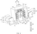
- the heating body 210 has a rectangular box shape and comprises a drying space 211 through which the electrode 10 passes, an inlet 212 which is provided in a left surface (a left surface of the heating body when viewed in FIG. 1 ) and through which the supplied electrode 10 is introduced, an outlet 213 which is provided in a right surface (a right surface of the heating body when viewed in FIG. 1 ) and through which the electrode 10 introduced into the drying space 211 is discharged, and a cover 214 coupled to one surface (a front surface of the heating body when viewed in FIG. 1 ) between the inlet 212 and the outlet 213.
- the cover 214 may be separated from the heating body 210 to open the drying space 211 so that the drying space 211 communicates with the outside.
- the electrode 10 is introduced into the drying space 211 through the inlet 212, and then, the electrode 10 introduced into the drying space 211 is discharged through the outlet 213.
- the cover 214 may be attached and detached to open and close the drying space 211.
- the cover 214 may be made of a transparent or translucent heat-resistant material. Thus, the drying space 211 may be easily recognized from the outside.
- the heating member 220 may be configured to directly dry the electrode introduced into the drying space 211 of the heating body.
- the heating member 220 comprises a mounting part 221 provided in the drying space 211 and a plurality of heating lamps 222 installed in the mounting part 221 and disposed close to the surface of the electrode 10 to directly heat and dry the surface of the electrode 10 and thereby to remove the moisture remaining on the electrode 10.
- the mounting part 221 may have a structure in which the plurality of heating lamps 222 provided in the drying space 211 are more easily replaced.
- the mounting part 221 comprises a fixed plate 221a provided in the drying space 211 and a guide plate 221b which is slidably coupled to the fixed plate 221a and on which the plurality of heating lamps 222 are installed. That is, referring to FIG. 4 , a guide groove 221a-1 is formed in the fixed plate 221a, and a guide protrusion 221b-1 slidably coupled to the guide groove 221a-1 is formed on the guide plate 221b.
- the guide plate 221b may be easily taken out of the drying space 211 by the guide groove 221a-1 and the guide protrusion 221b-1.
- the plurality of heating lamps 222 installed on the guide plate 221b may be easily replaced outside the drying space 211 to facilitate maintenance.
- the guide plate 221b may be coupled to the fixed plate 221a so as to be slid toward the cover 214.
- the plurality of heating lamps 222 installed on the guide plate 221b may be taken out of the drying space 211 only by the small movement of the guide plate 221b.
- the guide plate 221b may be slid along the guide groove 221a-1 of the fixed plate 221a to allow the plurality of heating lamps 222 and the surface of the electrode 10 to match each other.
- the guide plate 221b may be detachably coupled to the fixed plate 221a. That is, when the plurality of heating lamps 222 are replaced, the replacement of the plurality of heating lamps 222 is performed outside the drying space 211 after the guide plate 221b is detached from the fixed plate 221a. Then, when the replacement of the heating lamps 222 is completed, the guide plate 221b is coupled again to the fixed plate 221a.
- Each of the fixed plate 221a and the guide plate 221b of the mounting part 221 may be a heatsink plate made of a heat dissipation material, which absorbs heat generated in the plurality of heating lamps 222 to release the heat to the outside. Thus, an increase in temperature of the heating lamps 222 may be suppressed.
- each of the heating lamps 222 comprises a power source part 222a installed on the guide plate 221b to receive current from the outside and a light source part 222b emitting light by the current supplied from the power source part 222a.
- the light source part 222b may be disposed close to the surface of the electrode 10.
- the light source part 222b may be disposed to be spaced a distance ' ⁇ ', which is illustrated in FIG. 4 , from the surface of the electrode 10. That is, the light source part 222b may be disposed a distance of 2 mm to 10 mm from the surface of the electrode 10. That is, when the light source part 222b is spaced a distance of 2 mm or less from the surface of the electrode 10, the electrode 10 may be damaged due to friction between the light source part 222b and the electrode 10.
- the light source part 222b When the light source part 222b is spaced a distance of 10 mm or more from the surface of the electrode 10, the light emitted from the light source part 222b is irradiated onto the surface of the electrode 10 in a diffused state to deteriorate a drying rate of the electrode 10.
- the heating lamp 222 may be disposed to be spaced a distance of 2 mm to 10 mm from the surface of the electrode 10 to stably dry the electrode 10 and thereby to remove the moisture remaining on the electrode 10 without damaging the electrode 10.
- the heating lamp 222 may be an infrared lamp or a xenon lamp.
- the infrared lamp comprises a near-infrared lamp, a medium-infrared lamp, and a far-infrared lamp.
- the far-infrared lamp is used as the infrared lamp.
- the far-infrared lamp may emit an infrared ray having a wavelength of 25 ⁇ m or more, which is greater than that of the visible light.
- the infrared ray may be invisible to the eye and have the high heat effect and the strong penetration power to realize the superior drying efficiency.
- the xenon light may be brighter than the filament and also may emit light from the bulb, but from the filament, to more widely and quickly dry the surface of the electrode. Particularly, the xenon light may have the lifespan longer than that of the filament to greatly reduce the maintenance cost.
- the plurality of heating lamps 222 may be regularly or irregularly installed on the guide plate 221b. Particularly, a distance between the plurality of heating lamps 222, which are regularly or irregularly installed on the guide plate 221b, may be a distance in which portions of the light irradiated onto the electrode 10 overlap each other. Thus, the entire surface of the electrode 10 may be directly heated and dried.
- the heating device 200 may further comprise a transfer roller transferring the electrode introduced into the drying space 211 and constantly maintaining tension force.
- the transfer roller 230 may have a structure in which the electrode 10 introduced into the drying space 211 is circulated with a maximally long length.
- the heating member 220 may directly heat the electrode 10 transferred along the transfer roller 230 to more effectively remove the moisture remaining on the electrode 10.
- the transfer roller 230 comprises a first transfer roller 231 disposed on a side of the inlet 212 of the drying space 211, a second transfer roller 232 disposed on an upper portion of the left surface of the drying space 211, a third transfer roller 233 disposed on an upper portion of the right surface of the drying space 211, and a fourth transfer roller 234 disposed on a side of the outlet 213 of the drying space 211.
- the inlet 212 is disposed on a lower end of the left surface of the drying space 211
- the outlet 213 is disposed on a lower end of the right surface of the drying space 211.
- the transfer roller 230 may transfer the electrode introduced into the drying space 211 along the left surface, a top surface, and the right surface of the drying space.
- a length and a residence time of the electrode introduced into the drying space 211 may increase, and thus, a drying time through the heating member 220 may naturally increase.
- the heating member 220 may be provided between the first transfer roller 231 and the second transfer roller 232, between the second transfer roller 232 and the third transfer roller 233, and between the third transfer roller 233 and the fourth transfer roller 234.
- the electrode 10 transferred along the first to fourth transfer rollers 231, 232, 233, and 234 may be directly heated and dried for a long time through the heating member 220 to completely remove the moisture remaining on the electrode 10.
- the heating member 220 may dry both surfaces of the electrode 10 at the same time so that the heating rate of the electrode 10 increases. That is, the heating member 220 may be disposed to correspond to both the surfaces of the electrode 10 to dry both the surfaces of the electrode 10 at the same time.
- the heating member 220 drying one surface (an outer surface of the electrode when viewed in FIG. 3 ) of the electrode 10, which faces the wall of the drying space 211, may be installed on the wall of the drying space 211.
- the heating member 220 drying the other surface (an inner surface of the electrode when viewed in FIG. 3 ) of the electrode 10 may be installed on an auxiliary frame 215 provided in the drying space 211.
- all the heating members 220 provided in the drying space 211 may be stably installed.
- the heating device 200 may further comprise an exhaust member 240 discharging air containing the moisture in the drying space 211 to the outside.
- the heating device 200 may quickly discharge the moisture evaporated from the surface of the electrode 10 through the exhaust member 240 to increase in drying rate of the electrode 10.
- the exhaust member 240 is disposed on the outer surface of the heating body 210, more preferably, an upper portion of a rear surface of the heating body 210 when viewed in FIG. 2 . That is, when the exhaust member 240 is disposed on the top surface of the heating body 210, hot air in the drying space 211 and cold air outside the exhaust member 240 may contact each other to generate droplets on a boundary line between the heating body 210 and the exhaust member 240.
- the exhaust member 240 may be installed on the upper portion of the rear surface of the heating body 210 so that the hot air in the drying space 211 is bypassed to a lower portion of the drying space 211 to decrease in temperature and then is discharged to prevent the droplets from being generated on the boundary line between the heating body 210 and the exhaust member 240.
- the exhaust member 240 comprises an exhaust duct 241 disposed on the outer surface of the heating body 210 to discharge the air within the drying space 211 to the outside and an exhaust pump 242 generating suction force to forcibly discharge the air within the drying space 211 to the outside through the exhaust duct 241.
- the air containing the moisture within the drying space 211 may be more quickly forcibly discharged to the outside, and thus, the drying rate may increase.
- the electrode heating device 200 comprising the above-described constituents according to the first embodiment of the present invention may directly heat and dry the surface of the electrode 10 to quickly remove the moisture remaining on the electrode 10.
- the working time may be significantly reduced to significantly improve productivity.
- a manufacturing system for a secondary battery according to a second embodiment of the present invention comprises a supply device 100 supplying an electrode 10, an electrode heating device 200 drying the electrode 10 supplied from the supply device 100, and a collection device 300 collecting the electrode 10 dried by the electrode heating device 200.
- the supply device 100 comprises a supply body 110 configured to supply the electrode 10 and comprising a bottom plate and a support plate disposed on correspond to each of both sides of the bottom plate, a supply roller 120 rotatably disposed between the support plates of the supply body 110 to supply the wound electrode 10, a supply motor 130 rotating the supply roller 120 to supply the wound electrode 10 to the supply roller 120, and a supply guide roller 140 guiding the electrode 10 supplied from the supply roller 120 and adjusting tension force.
- the supply roller 120 rotates within the supply body 110 by driving force of the supply motor 130.
- the wound electrode 10 is gradually unwound while the supply roller 120 rotates and then is supplied to the electrode heating device 200.
- the electrode 10 supplied from the supply roller 120 has uniform tension force while being guided by the supply guide roller 140.
- the electrode heating device 200 comprises a heating body 210 through which the electrode 10 supplied from the supply device 100 passes and a heating member 220 directly heating and drying a surface of the electrode passing through the heating body 210 to remove moisture remaining on the electrode 10.
- the electrode heating device may have the same constituents as those of the electrode heating device according to the foregoing first embodiment, and thus, their duplicated description will be omitted.
- the collection device 300 is configured to collect the dried electrode 10 passing through the electrode heating device 200 and comprises a collection body 310 comprising a bottom plate and a support plate disposed to correspond to each of both sides of the bottom plate, a collection roller 320 rotatably disposed between the support plates of the collection roller 310 to wind and collect the electrode 10 discharged from the electrode heating device 200, a collection motor 330 rotating the collection roller 320 to wind the electrode 10, and a collection guide roller 340 guiding the electrode 10 collected from the collection roller 120 and adjusting tension force.
- a collection body 310 comprising a bottom plate and a support plate disposed to correspond to each of both sides of the bottom plate
- a collection roller 320 rotatably disposed between the support plates of the collection roller 310 to wind and collect the electrode 10 discharged from the electrode heating device 200
- a collection motor 330 rotating the collection roller 320 to wind the electrode 10
- a collection guide roller 340 guiding the electrode 10 collected from the collection roller 120 and adjusting tension force.
- the collection device may stably collect the electrode 10 discharged from the electrode heating device 200 while maintaining the tension force.
- the surface of the electrode may be directly heated and dried to quickly remove the moisture remaining on the electrode, thereby reducing the drying time and improving the productivity.
- an electrode 10 is introduced into a drying space 211 through an inlet 212 formed in a heating body 210 of an electrode heating device 200, and the electrode 10 introduced into the drying space 211 is transferred along first to fourth transfer rollers 231, 232, 233, and 234 of a transfer roller 230. Then, the electrode transferred along the first to fourth transfer rollers 231, 232, 233, and 234 is continuously dried by heating members 220, which are respectively disposed between the first transfer roller 231 and the second transfer roller 232, between the second transfer roller 232 and the third transfer roller 233, and between the third transfer roller 233 and the fourth transfer roller 234.
- each of the heating members 220 may directly heat and dry both surfaces of the electrode 10 through a plurality of heating lamps 222 to quickly remove moisture remaining on the electrode 10, and an exhaust member 240 may discharge air within the drying space 211 to the outside to increase in drying rate of the electrode 10.
- the plurality of heating lamps 222 may be taken out of the drying space 211 through a fixed plate 221a and a guide plate 221b of a mounting part 221 provided in the heating member 220.
- the heating lamp may be easily replaced.
- the electrode 10 transferred through the fourth transfer roller 234 may be discharged through an outlet 213 of the heating body 210, and the electrode 10 discharged through the outlet 213 may be collected while being wound around the collection device 300.
- a manufacturing system for a secondary battery comprises a manufacturing device 400 manufacturing an electrode 10, an electrode heating device 200 directly heating and drying a surface of the electrode 10 manufactured by the manufacturing device 400 to remove moisture remaining on the electrode 10, and a lamination device 500 alternately laminating the electrode 10, from which the moisture is removed by the electrode heating device 200, and a separator 20 to bond the electrode 10 and the separator 20 to each other by using heat and a pressure.
- the manufacturing device 400 comprises a supply roller 410 supplying a collector 11 and a coating member 420 applying an electrode active material to a surface of the collector 11 supplied by the supply roller 110. That is, in the manufacturing device 400, the electrode active material may be applied to the surface of the collector 11 supplied by the supply roller 410 through the coating member 420 to manufacture the electrode 10.
- the electrode heating device 200 comprises a heating body 210 having a drying space 211 through which the electrode 10 manufactured by the manufacturing device 400 passes and a heating member 220 directly heating and drying the surface of the electrode 10 passing through the drying space 211 to remove the moisture remaining on the electrode 10.
- the electrode heating device may have the same constituents as those of the electrode heating device according to the foregoing first embodiment, and thus, their duplicated description will be omitted.
- the electrode 10, from which the moisture is removed by the heating device 200, and the separator 20 supplied from a separator supply roller (not shown) are alternately laminated to be bonded to each other by the heat and pressure.
- the electrode 10 and the separator 20 may be more stably thermally bonded to each other.
- the surface of the electrode 10 manufactured by the manufacturing device 400 may be directly heated and dried through the electrode heating device 200 to quickly remove the moisture remaining on the electrode 10.
- the drying time may be reduced, and the productivity may be improved.
- the electrode 10 and the separator 20 may be more stably thermally bonded to each other through the lamination device 500.
- an electrode active material 12 is applied to a surface of a collector 11 through a manufacturing device 400 to manufacture an electrode 10.
- the manufactured electrode 10 is introduced into a drying space 211 through an inlet 212 formed in a heating body 210 of a heating device 200, and the electrode 10 introduced into the drying space 211 is transferred along first to fourth transfer rollers 231, 232, 233, and 234 of a transfer roller 230.
- the electrode 10 transferred along the first to fourth transfer rollers 231, 232, 233, and 234 may be continuously heated and dried by heating members 220, which are respectively disposed between the first transfer roller 231 and the second transfer roller 232, between the second transfer roller 232 and the third transfer roller 233, and between the third transfer roller 233 and the fourth transfer roller 234.
- heating members 220 which are respectively disposed between the first transfer roller 231 and the second transfer roller 232, between the second transfer roller 232 and the third transfer roller 233, and between the third transfer roller 233 and the fourth transfer roller 234.
- the moisture remaining on the electrode 10 may be completely removed.
- each of the heating members 220 may directly heat and dry both surfaces of the electrode 10 through a plurality of heating lamps 222 to quickly remove the moisture remaining on the electrode 10, and an exhaust member 240 may discharge air within the drying space 211 to the outside to increase in drying rate of the electrode 10.
- the plurality of heating lamps 222 may be taken out of the drying space 211 through a fixed plate 221a and a guide plate 221b of a mounting part 221 provided in the heating member 220.
- the heating lamp may be easily replaced.
- the electrode 10 transferred through the fourth transfer roller 234 may be discharged through an outlet 213 of the heating body 210, and then, the electrode 10 discharged through the outlet 213 and the separator 10 may be introduced into a lamination device 500 in a state in which the electrode 10 and the separator 20 are laminated and be thermally bonded to each other.
- the electrode 10 and the separator 20 may be stably thermally bonded to each other.
Landscapes
- Engineering & Computer Science (AREA)
- Chemical & Material Sciences (AREA)
- General Chemical & Material Sciences (AREA)
- Electrochemistry (AREA)
- Chemical Kinetics & Catalysis (AREA)
- Manufacturing & Machinery (AREA)
- General Engineering & Computer Science (AREA)
- Mechanical Engineering (AREA)
- Microbiology (AREA)
- Life Sciences & Earth Sciences (AREA)
- Combustion & Propulsion (AREA)
- Textile Engineering (AREA)
- Battery Electrode And Active Subsutance (AREA)
- Drying Of Solid Materials (AREA)
Claims (9)
- Elektroden-Erwärmung-Vorrichtung (200) zum Trockenen einer Elektrode (10), umfassend:einen Erwärmung-Körper (210), welcher einen Trocknungsraum (211) aufweist, durch welchen die Elektrode hindurchtritt; undein Erwärmung-Element (220), welches eine Fläche der Elektrode, welche durch den Trocknungsraum hindurchtritt, direkt erwärmt und trocknet, welches dazu eingerichtet ist, Feuchtigkeit zu entfernen, welche an der Elektrode verbleibt,wobei das Erwärmung-Element umfasst:einen Montage-Teil (221), welcher in dem Trocknungsraum bereitgestellt ist; und eine Mehrzahl von Erwärmung-Lampen (222), welche an dem Montage-Teil installiert sind und nahe zu der Fläche der Elektrode angeordnet sind, um die Fläche der Elektrode direkt zu erwärmen und zu trocknen, wodurch die Feuchtigkeit entfernt wird, welche an der Elektrode verbleibt,wobei der Montage-Teil umfasst:eine befestigte Platte (221a), welche in dem Trocknungsraum bereitgestellt ist; undeine Führung-Platte (221b), welche mit der befestigten Platte gleitbar gekoppelt ist, und an welcher die Mehrzahl von Erwärmung-Lampen installiert sind,wobei der Erwärmung-Körper umfasst:einen Einlass (212), welcher in einer linken Fläche bereitgestellt ist und durch welchen die Elektrode eingeführt wird, einen Auslass (213),welcher in einer rechten Fläche bereitgestellt ist und durch welchen die Elektrode, welche in den Trocknungsraum eingeführt worden ist,abgegeben wird, und eine Abdeckung (214), welche mit einer Fläche zwischen dem Einlass und dem Auslass gekoppelt ist,wobei die Abdeckung dazu eingerichtet ist, geöffnet zu werden, während sie von dem Erwärmung-Körper getrennt ist, so dass der Trocknungsraum mit der Außenseite kommuniziert, unddie Führung-Platte mit der befestigten Platte gekoppelt ist, um in Richtung der Abdeckung geschoben zu werden, und aus dem Trocknungsraum herausgenommen wird, wenn die Abdeckung geöffnet ist,wobei jede aus der befestigten Platte und der Führung-Platte aus einem Wärme-Verteilung-Material hergestellt ist, welches Wärme absorbiert,welche von der Mehrzahl von Erwärmung-Lampen erzeugt wird, um die Wärme an die Außenseite abzugeben,wobei eine Führung-Nut (221a-1) in der befestigten Platte gebildet ist und ein Führung-Vorsprung (221b-1), welcher mit der Führung-Nut gleitbar gekoppelt ist, an der Führung-Platte gebildet ist,wobei die Erwärmung-Lampe um eine Distanz von 2 mm bis 10 mm von der Fläche der Elektrode beabstandet ist.
- Elektroden-Erwärmung-Vorrichtung nach Anspruch 1, wobei eine Übertragung-Rolle (230), welche die Elektrode, welche in den Trocknungsraum eingeführt worden ist, überträgt, ferner in dem Erwärmung-Körper bereitgestellt ist,
wobei die Übertragung-Rolle eine erste Übertragung-Rolle (231), welche an einer Einlass-Seite des Trocknungsraums angeordnet ist, eine zweite Übertragung-Rolle (232), welche an einem oberen Abschnitt der linken Fläche des Trocknungsraums angeordnet ist, eine dritte Übertragung-Rolle (233), welche an einem oberen Abschnitt der rechten Fläche des Trocknungsraums angeordnet ist, und eine vierte Übertragung-Rolle (234) umfasst, welche an einer Auslass-Seite des Trocknungsraums angeordnet ist,
wobei das Erwärmung-Element an wenigstens einer oder mehreren Stellen zwischen der ersten Übertragung-Rolle und der zweiten Übertragung-Rolle, zwischen der zweiten Übertragung-Rolle und der dritten Übertragung-Rolle und zwischen der dritten Übertragung-Rolle und der vierten Übertragung-Rolle bereitgestellt ist, und
wobei die Elektrode, welche in den Trocknungsraum eingeführt worden ist, entlang den ersten bis vierten Übertragung-Rollen übertragen wird und durch das Erwärmung-Element getrocknet wird. - Elektroden-Erwärmung-Vorrichtung nach Anspruch 2, wobei das Erwärmung-Element bereitgestellt ist, jeder aus beiden Flächen der Elektrode zu entsprechen, um die beiden Flächen der Elektrode zu der gleichen Zeit direkt zu erwärmen und zu trocknen.
- Elektroden-Erwärmung-Vorrichtung nach Anspruch 3, wobei das Erwärmung-Element, welches eine Fläche der Elektrode erwärmt, welche zu einer Wand des Trocknungsraums weist, an der Wand des Trocknungsraums installiert ist, und
das Erwärmung-Element, welches die äußere Fläche der Elektrode trocknet, an einem Hilfs-Rahmen (215) installiert ist, welcher in dem Trocknungsraum bereitgestellt ist. - Elektroden-Erwärmung-Vorrichtung nach Anspruch 1, ferner umfassend ein Abgas-Element (240), welches Luft, welche die Feuchtigkeit innerhalb des Trocknungsraums enthält, zu der Außenseite abgibt.
- Elektroden-Erwärmung-Vorrichtung nach Anspruch 5, wobei das Abgas-Element eine Abgas-Leitung (241), welche an einer äußeren Fläche des Erwärmung-Körpers angeordnet ist, um die Luft innerhalb des Trocknungsraums an die Außenseite abzugeben, und eine Abgas-Pumpe (242) umfasst, welche eine Saugkraft erzeugt, um die Luft innerhalb des Trocknungsraums an die Außenseite zwangsweise durch die Abgas-Leitung abzugeben.
- Elektroden-Erwärmung-Vorrichtung nach Anspruch 1, wobei die Erwärmung-Lampe eine Infrarot-Lampe oder eine Xenon-Lampe ist.
- Herstellung-System für eine Sekundärbatterie, umfassend:eine Liefer-Vorrichtung (100), welche eine Elektrode (10) liefert;eine Elektroden-Erwärmung-Vorrichtung nach den Ansprüchen 1 bis 7, welche eine Fläche der Elektrode, welche von der Liefer-Vorrichtung geliefert worden ist, direkt erwärmt und trocknet, welche dazu eingerichtet ist, Feuchtigkeit zu entfernen, welche an der Elektrode verbleibt; undeine Sammel-Vorrichtung (300), welche die Elektrode sammelt, von welcher die Feuchtigkeit durch die Elektroden-Erwärmung-Vorrichtung entfernt worden ist,wobei die Elektroden-Erwärmung-Vorrichtung umfasst:einen Erwärmung-Körper (210), welcher einen Trocknungsraum (211) aufweist, durch welchen die von der Liefer-Vorrichtung gelieferte Elektrode hindurchtritt; undein Erwärmung-Element (220), welches die Fläche der Elektrode, welche durch den Trocknungsraum hindurchtritt, direkt erwärmt und trocknet, um die Feuchtigkeit zu entfernen, welche an der Elektrode verbleibt.
- Herstellung-System für eine Sekundärbatterie, umfassend:eine Herstellung-Vorrichtung (400), welche eine Elektrode (10) herstellt; eine Elektroden-Erwärmung-Vorrichtung nach den Ansprüchen 1 bis 7, welche eine Fläche der Elektrode, welche durch die Herstellung-Vorrichtung hergestellt worden ist, direkt erwärmt und trocknet, welche dazu eingerichtet ist, Feuchtigkeit zu entfernen, welche an der Elektrode verbleibt; undeine Laminierung-Vorrichtung (500), welche die Elektrode alternierend laminiert, von welcher die Feuchtigkeit durch die Elektroden-Erwärmung-Vorrichtung entfernt worden ist, und einen Separator (20), um die Elektrode und den Separator miteinander unter Verwendung von Wärme und einem Druck zu verbinden,wobei die Elektroden-Erwärmung-Vorrichtung umfasst:einen Erwärmung-Körper (210), welcher einen Trocknungsraum aufweist, durch welchen die von der Herstellung-Vorrichtung hergestellte Elektrode hindurchtritt und ein Erwärmung-Element (220),welches die Fläche der Elektrode, welche durch den Trocknungsraum hindurchtritt, direkt erwärmt und trocknet, welches dazu eingerichtet ist, die Feuchtigkeit zu entfernen, welche an der Elektrode verbleibt.
Priority Applications (1)
| Application Number | Priority Date | Filing Date | Title |
|---|---|---|---|
| PL18846383T PL3496187T3 (pl) | 2017-08-17 | 2018-07-16 | Urządzenie do ogrzewania elektrody i zawierający je układ do wytwarzania baterii akumulatorowej |
Applications Claiming Priority (4)
| Application Number | Priority Date | Filing Date | Title |
|---|---|---|---|
| KR20170103996 | 2017-08-17 | ||
| KR20170103995 | 2017-08-17 | ||
| KR1020180075224A KR102516223B1 (ko) | 2017-08-17 | 2018-06-29 | 전극 가열장치 및 그를 포함하는 이차전지용 제조시스템 |
| PCT/KR2018/008044 WO2019035564A1 (ko) | 2017-08-17 | 2018-07-16 | 전극 가열장치 및 그를 포함하는 이차전지용 제조시스템 |
Publications (3)
| Publication Number | Publication Date |
|---|---|
| EP3496187A1 EP3496187A1 (de) | 2019-06-12 |
| EP3496187A4 EP3496187A4 (de) | 2019-09-04 |
| EP3496187B1 true EP3496187B1 (de) | 2021-02-24 |
Family
ID=65560978
Family Applications (1)
| Application Number | Title | Priority Date | Filing Date |
|---|---|---|---|
| EP18846383.0A Active EP3496187B1 (de) | 2017-08-17 | 2018-07-16 | Elektrodenheizvorrichtung und sekundärbatterieherstellungssystem damit |
Country Status (5)
| Country | Link |
|---|---|
| US (1) | US11196034B2 (de) |
| EP (1) | EP3496187B1 (de) |
| KR (1) | KR102516223B1 (de) |
| CN (1) | CN109792034B (de) |
| PL (1) | PL3496187T3 (de) |
Families Citing this family (14)
| Publication number | Priority date | Publication date | Assignee | Title |
|---|---|---|---|---|
| KR102752344B1 (ko) * | 2019-08-01 | 2025-01-10 | 주식회사 엘지에너지솔루션 | 수분공급부가 구비된 전극 건조 장치 및 이를 이용한 전극 건조 방법 |
| DE102019220279B4 (de) | 2019-08-22 | 2023-08-10 | Smartec Co., Ltd. | Trocknungsgerät für Batterieelektrode |
| KR102851596B1 (ko) * | 2019-10-22 | 2025-08-28 | 주식회사 엘지에너지솔루션 | 이차전지용 파우치 필름 성형 장치 및 방법 |
| CN110626063A (zh) * | 2019-11-08 | 2019-12-31 | 安徽双盈纺织有限公司 | 一种转移印纸机用烘干装置 |
| KR102824103B1 (ko) * | 2020-02-03 | 2025-06-23 | 주식회사 엘지에너지솔루션 | 전극 건조장치 및 그를 포함하는 전극 건조설비 |
| KR102388446B1 (ko) * | 2020-06-11 | 2022-04-21 | 주식회사 나래나노텍 | 배터리용 전극 시트 건조 장치 및 배터리용 전극 시트 건조 방법 |
| KR102903643B1 (ko) * | 2021-05-20 | 2025-12-29 | 주식회사 나래나노텍 | 전극 건조장치 |
| US20230371131A1 (en) * | 2021-06-29 | 2023-11-16 | Lg Energy Solution, Ltd. | Secondary Battery Lamination Device Using Infrared Lamps |
| KR20230122932A (ko) * | 2022-02-15 | 2023-08-22 | 주식회사 엘지에너지솔루션 | 이차전지 제조장치 및 이를 이용하는 이차전지 제조방법 |
| CN114674141B (zh) * | 2022-04-15 | 2024-11-26 | 东莞市德瑞精密设备有限公司 | 电池夹具推拉装置及电池干燥生产线 |
| KR102851023B1 (ko) * | 2023-04-12 | 2025-08-27 | 주식회사 에스에프에이 | 이차전지 전극 제조용 하이브리드 건조시스템 |
| CN118043616A (zh) * | 2022-06-28 | 2024-05-14 | 宁德时代新能源科技股份有限公司 | 烘干装置、极片制造设备和极片烘干方法 |
| KR20250024400A (ko) * | 2023-08-11 | 2025-02-18 | 주식회사 엘지에너지솔루션 | 전극 가열 장치 |
| KR20250089664A (ko) | 2023-12-12 | 2025-06-19 | 현대자동차주식회사 | 전극의 건조시스템 및 제조방법 |
Family Cites Families (42)
| Publication number | Priority date | Publication date | Assignee | Title |
|---|---|---|---|---|
| US2668364A (en) * | 1950-10-27 | 1954-02-09 | Dry Freeze Corp | Drying of materials by infrared radiation |
| GB713612A (en) | 1951-10-29 | 1954-08-11 | Petrus Vial | Process and apparatus for the recovery of solvents on long webs |
| US5595118A (en) * | 1995-10-16 | 1997-01-21 | F & L Machinery Design, Inc. | Drying apparatus for a dry off-set printing press having an ultra-violet lamp assembly |
| JPH09129221A (ja) * | 1995-10-27 | 1997-05-16 | Toshiba Battery Co Ltd | 乾燥装置 |
| JP3225871B2 (ja) * | 1996-12-26 | 2001-11-05 | 三菱電機株式会社 | リチウムイオン二次電池の製造方法 |
| GB2336895A (en) | 1998-04-30 | 1999-11-03 | Gew | UV dryer with shaped reflector surface |
| DE29916572U1 (de) * | 1999-09-21 | 1999-12-23 | Print Concept GmbH, 73240 Wendlingen | Trocknungseinrichtung für beschichtete Substrate |
| JP3953911B2 (ja) * | 2002-08-08 | 2007-08-08 | 松下電器産業株式会社 | 塗膜シートの製造方法 |
| US7344296B2 (en) * | 2003-02-07 | 2008-03-18 | Matsushita Electric Industrial Co., Ltd. | Socket for led light source and lighting system using the socket |
| JP2006012712A (ja) | 2004-06-29 | 2006-01-12 | Nitta Ind Corp | セパレータの製造方法 |
| KR101045958B1 (ko) | 2004-02-13 | 2011-07-04 | 엘지전자 주식회사 | 공기조화기의 히터 장착 구조 |
| US20060201017A1 (en) * | 2005-03-10 | 2006-09-14 | Ellis Gregory P | System, apparatus and method for curing of coatings in heavy gas |
| GB2448538A (en) * | 2007-04-19 | 2008-10-22 | Nordson Corp | Lamp assembly and cooling thereof |
| KR101126769B1 (ko) | 2009-09-22 | 2012-03-29 | 삼성에스디아이 주식회사 | 다수의 3상 전원 램프를 포함하는 램프 히터 및 이를 이용한 이차 전지 제조용 건조 장치 |
| DE102009045240A1 (de) * | 2009-10-01 | 2011-04-07 | Robert Bosch Gmbh | Verfahren zur Herstellung einer Keramik-Elektrodenseparatorvorrichtung |
| JP5249916B2 (ja) * | 2009-12-24 | 2013-07-31 | 三菱重工業株式会社 | 電極乾燥装置 |
| CN103109397B (zh) | 2010-09-29 | 2016-02-24 | 爱斯佩克株式会社 | 电极对干燥法、锂离子二次电池制造法、双电层电容器制造法、锂离子电容器制造法 |
| JP2012251763A (ja) * | 2011-05-12 | 2012-12-20 | Sharp Corp | 電極乾燥装置、及び電極乾燥方法 |
| CN202177080U (zh) * | 2011-08-16 | 2012-03-28 | 河南新思维光电科技有限公司 | 一种应用硅胺脂发泡散热材料的led灯具 |
| CN103017496B (zh) * | 2011-09-22 | 2016-01-13 | 北京奥思源科技有限公司 | 锂离子动力电池极片干燥装置及方法 |
| CN202284725U (zh) * | 2011-09-30 | 2012-06-27 | 福州小糸大亿车灯有限公司 | 多用途hid氙气照明灯 |
| JP5831223B2 (ja) | 2011-12-28 | 2015-12-09 | 日産自動車株式会社 | 電極乾燥方法、電極乾燥制御方法、電極乾燥装置および電極乾燥制御装置 |
| KR101192619B1 (ko) * | 2012-03-23 | 2012-10-18 | 주식회사 엘지화학 | 전지케이스 |
| CN103807829A (zh) * | 2012-11-14 | 2014-05-21 | 永发精密开发有限公司 | Led灯管制作方法 |
| JP6314832B2 (ja) | 2012-11-26 | 2018-04-25 | 日本ゼオン株式会社 | 電極/セパレータ積層体の製造方法およびリチウムイオン二次電池 |
| JP5984643B2 (ja) | 2012-11-29 | 2016-09-06 | 株式会社メイコー | 電極シート乾燥装置及び電極シート乾燥方法 |
| JP6137825B2 (ja) | 2012-12-18 | 2017-05-31 | 昭和電工パッケージング株式会社 | ドライラミネート方法および成形用包装材の製造方法 |
| JP5325332B1 (ja) | 2012-12-28 | 2013-10-23 | 日本碍子株式会社 | 電池用電極塗膜の乾燥方法及び乾燥炉 |
| KR101532730B1 (ko) * | 2013-01-16 | 2015-06-30 | 주식회사 엘지화학 | 전극조립체의 제조장치 |
| KR102007698B1 (ko) | 2013-01-23 | 2019-08-06 | 삼성에스디아이 주식회사 | 이차 전지의 전극 기재용 건조장치 및 그 제어방법 |
| KR101572720B1 (ko) | 2013-09-13 | 2015-11-27 | 주식회사 엘지화학 | 전극조립체의 권취장치 |
| KR20150034973A (ko) * | 2013-09-27 | 2015-04-06 | 제일모직주식회사 | 건조장치 및 건조방법 |
| KR101586121B1 (ko) | 2013-09-30 | 2016-01-22 | 주식회사 엘지화학 | 전극 가이드를 포함하는 라미네이션 장치 |
| CN204062595U (zh) * | 2014-08-26 | 2014-12-31 | 蔡鸿 | 一种led灯具 |
| US20160093880A1 (en) * | 2014-09-29 | 2016-03-31 | Lg Chem, Ltd. | Method for manufacturing electrode and electrode manufactured by the same |
| CN105891551A (zh) * | 2014-10-04 | 2016-08-24 | 平湖铱能新能源有限公司 | 一种带排线槽的日光灯测试架 |
| DE202015106039U1 (de) * | 2015-11-10 | 2017-02-13 | Autefa Solutions Germany Gmbh | Behandlungseinrichtung |
| CN205249626U (zh) * | 2015-12-25 | 2016-05-18 | 遂宁威士凯科技有限公司 | 一种节能型热风循环式烘烤装置 |
| CN105618089B (zh) | 2016-01-20 | 2018-09-14 | 华南理工大学 | 一种Ag@AgCl修饰富勒烯/阴离子粘土复合光催化剂及其制备与应用 |
| CN105486059B (zh) * | 2016-01-21 | 2017-12-22 | 山东裴森动力新能源有限公司 | 一种锂离子电池极片烘干装置 |
| CN205758039U (zh) * | 2016-04-15 | 2016-12-07 | 贵州大学 | 一种可拆卸的电暖茶几 |
| CN206073623U (zh) * | 2016-10-08 | 2017-04-05 | 威海三合永新能源科技有限公司 | 一种用于超级电容器极片辊压时的烘烤装置 |
-
2018
- 2018-06-29 KR KR1020180075224A patent/KR102516223B1/ko active Active
- 2018-07-16 EP EP18846383.0A patent/EP3496187B1/de active Active
- 2018-07-16 PL PL18846383T patent/PL3496187T3/pl unknown
- 2018-07-16 US US16/330,224 patent/US11196034B2/en active Active
- 2018-07-16 CN CN201880003663.5A patent/CN109792034B/zh active Active
Non-Patent Citations (1)
| Title |
|---|
| None * |
Also Published As
| Publication number | Publication date |
|---|---|
| US11196034B2 (en) | 2021-12-07 |
| CN109792034A (zh) | 2019-05-21 |
| EP3496187A1 (de) | 2019-06-12 |
| EP3496187A4 (de) | 2019-09-04 |
| KR102516223B1 (ko) | 2023-03-30 |
| US20190229324A1 (en) | 2019-07-25 |
| KR20190019828A (ko) | 2019-02-27 |
| CN109792034B (zh) | 2022-07-26 |
| PL3496187T3 (pl) | 2021-07-05 |
Similar Documents
| Publication | Publication Date | Title |
|---|---|---|
| EP3496187B1 (de) | Elektrodenheizvorrichtung und sekundärbatterieherstellungssystem damit | |
| US11581520B2 (en) | Notching apparatus and method for secondary battery | |
| US11594713B2 (en) | Notching apparatus and method for secondary battery | |
| KR101810146B1 (ko) | 이차전지 전극 제조용 건조기 | |
| TWI429871B (zh) | 電極乾燥裝置 | |
| CN115461886A (zh) | 电极干燥装置 | |
| CN107946539A (zh) | 涂布烘干设备 | |
| KR20220136082A (ko) | 전극 건조 장치 | |
| KR20230090522A (ko) | 전극 노칭 설비 및 그 제어방법 | |
| CN217797190U (zh) | 一种肤感板材干燥机 | |
| KR102502275B1 (ko) | 코안다 열풍기 및 이를 구비한 이차전지 전극 건조 장치 | |
| KR102784782B1 (ko) | 이차전지용 전극판 건조장치 | |
| ITRM20110319A1 (it) | Impianto di riscaldamento preforme di contenitori | |
| WO2019035564A1 (ko) | 전극 가열장치 및 그를 포함하는 이차전지용 제조시스템 | |
| CN209886117U (zh) | 涂布烘箱装置 | |
| CN109825996B (zh) | 一种新能源空气能循环被褥除湿烘干器 | |
| KR20220157008A (ko) | 전극 건조장치 | |
| EP4589233B1 (de) | Elektrodenherstellungssystem und verfahren zur herstellung einer elektrode | |
| US20250121406A1 (en) | Electrode manufacturing apparatus and electrode manufacturing method | |
| CN119346399B (zh) | 干燥烘箱以及涂布设备 | |
| CN221662116U (zh) | 一种锂电池电极片烤箱用的耐高温输送机构 | |
| KR102891247B1 (ko) | 전극 건조장치 | |
| KR20220126205A (ko) | 전극 건조 장치 | |
| CN120008319A (zh) | 烘干设备及极片制造系统 | |
| CN109244305A (zh) | 一种电芯模组加热装置 |
Legal Events
| Date | Code | Title | Description |
|---|---|---|---|
| STAA | Information on the status of an ep patent application or granted ep patent |
Free format text: STATUS: THE INTERNATIONAL PUBLICATION HAS BEEN MADE |
|
| PUAI | Public reference made under article 153(3) epc to a published international application that has entered the european phase |
Free format text: ORIGINAL CODE: 0009012 |
|
| STAA | Information on the status of an ep patent application or granted ep patent |
Free format text: STATUS: REQUEST FOR EXAMINATION WAS MADE |
|
| 17P | Request for examination filed |
Effective date: 20190304 |
|
| AK | Designated contracting states |
Kind code of ref document: A1 Designated state(s): AL AT BE BG CH CY CZ DE DK EE ES FI FR GB GR HR HU IE IS IT LI LT LU LV MC MK MT NL NO PL PT RO RS SE SI SK SM TR |
|
| AX | Request for extension of the european patent |
Extension state: BA ME |
|
| A4 | Supplementary search report drawn up and despatched |
Effective date: 20190806 |
|
| RIC1 | Information provided on ipc code assigned before grant |
Ipc: H01J 61/16 20060101ALI20190731BHEP Ipc: H05B 3/00 20060101ALI20190731BHEP Ipc: F26B 3/30 20060101ALI20190731BHEP Ipc: H01M 4/04 20060101AFI20190731BHEP Ipc: F26B 13/10 20060101ALI20190731BHEP Ipc: H01M 10/04 20060101ALI20190731BHEP Ipc: F26B 25/08 20060101ALI20190731BHEP Ipc: F26B 13/06 20060101ALI20190731BHEP |
|
| STAA | Information on the status of an ep patent application or granted ep patent |
Free format text: STATUS: EXAMINATION IS IN PROGRESS |
|
| 17Q | First examination report despatched |
Effective date: 20200205 |
|
| GRAP | Despatch of communication of intention to grant a patent |
Free format text: ORIGINAL CODE: EPIDOSNIGR1 |
|
| STAA | Information on the status of an ep patent application or granted ep patent |
Free format text: STATUS: GRANT OF PATENT IS INTENDED |
|
| DAV | Request for validation of the european patent (deleted) | ||
| DAX | Request for extension of the european patent (deleted) | ||
| INTG | Intention to grant announced |
Effective date: 20201125 |
|
| GRAS | Grant fee paid |
Free format text: ORIGINAL CODE: EPIDOSNIGR3 |
|
| GRAA | (expected) grant |
Free format text: ORIGINAL CODE: 0009210 |
|
| STAA | Information on the status of an ep patent application or granted ep patent |
Free format text: STATUS: THE PATENT HAS BEEN GRANTED |
|
| AK | Designated contracting states |
Kind code of ref document: B1 Designated state(s): AL AT BE BG CH CY CZ DE DK EE ES FI FR GB GR HR HU IE IS IT LI LT LU LV MC MK MT NL NO PL PT RO RS SE SI SK SM TR |
|
| REG | Reference to a national code |
Ref country code: CH Ref legal event code: EP |
|
| REG | Reference to a national code |
Ref country code: AT Ref legal event code: REF Ref document number: 1365609 Country of ref document: AT Kind code of ref document: T Effective date: 20210315 |
|
| REG | Reference to a national code |
Ref country code: IE Ref legal event code: FG4D |
|
| REG | Reference to a national code |
Ref country code: DE Ref legal event code: R096 Ref document number: 602018013177 Country of ref document: DE |
|
| REG | Reference to a national code |
Ref country code: SE Ref legal event code: TRGR |
|
| REG | Reference to a national code |
Ref country code: LT Ref legal event code: MG9D |
|
| REG | Reference to a national code |
Ref country code: NL Ref legal event code: MP Effective date: 20210224 |
|
| PG25 | Lapsed in a contracting state [announced via postgrant information from national office to epo] |
Ref country code: BG Free format text: LAPSE BECAUSE OF FAILURE TO SUBMIT A TRANSLATION OF THE DESCRIPTION OR TO PAY THE FEE WITHIN THE PRESCRIBED TIME-LIMIT Effective date: 20210524 Ref country code: GR Free format text: LAPSE BECAUSE OF FAILURE TO SUBMIT A TRANSLATION OF THE DESCRIPTION OR TO PAY THE FEE WITHIN THE PRESCRIBED TIME-LIMIT Effective date: 20210525 Ref country code: FI Free format text: LAPSE BECAUSE OF FAILURE TO SUBMIT A TRANSLATION OF THE DESCRIPTION OR TO PAY THE FEE WITHIN THE PRESCRIBED TIME-LIMIT Effective date: 20210224 Ref country code: HR Free format text: LAPSE BECAUSE OF FAILURE TO SUBMIT A TRANSLATION OF THE DESCRIPTION OR TO PAY THE FEE WITHIN THE PRESCRIBED TIME-LIMIT Effective date: 20210224 Ref country code: NO Free format text: LAPSE BECAUSE OF FAILURE TO SUBMIT A TRANSLATION OF THE DESCRIPTION OR TO PAY THE FEE WITHIN THE PRESCRIBED TIME-LIMIT Effective date: 20210524 Ref country code: PT Free format text: LAPSE BECAUSE OF FAILURE TO SUBMIT A TRANSLATION OF THE DESCRIPTION OR TO PAY THE FEE WITHIN THE PRESCRIBED TIME-LIMIT Effective date: 20210624 Ref country code: LT Free format text: LAPSE BECAUSE OF FAILURE TO SUBMIT A TRANSLATION OF THE DESCRIPTION OR TO PAY THE FEE WITHIN THE PRESCRIBED TIME-LIMIT Effective date: 20210224 |
|
| REG | Reference to a national code |
Ref country code: AT Ref legal event code: MK05 Ref document number: 1365609 Country of ref document: AT Kind code of ref document: T Effective date: 20210224 |
|
| PG25 | Lapsed in a contracting state [announced via postgrant information from national office to epo] |
Ref country code: LV Free format text: LAPSE BECAUSE OF FAILURE TO SUBMIT A TRANSLATION OF THE DESCRIPTION OR TO PAY THE FEE WITHIN THE PRESCRIBED TIME-LIMIT Effective date: 20210224 Ref country code: NL Free format text: LAPSE BECAUSE OF FAILURE TO SUBMIT A TRANSLATION OF THE DESCRIPTION OR TO PAY THE FEE WITHIN THE PRESCRIBED TIME-LIMIT Effective date: 20210224 Ref country code: RS Free format text: LAPSE BECAUSE OF FAILURE TO SUBMIT A TRANSLATION OF THE DESCRIPTION OR TO PAY THE FEE WITHIN THE PRESCRIBED TIME-LIMIT Effective date: 20210224 |
|
| PG25 | Lapsed in a contracting state [announced via postgrant information from national office to epo] |
Ref country code: IS Free format text: LAPSE BECAUSE OF FAILURE TO SUBMIT A TRANSLATION OF THE DESCRIPTION OR TO PAY THE FEE WITHIN THE PRESCRIBED TIME-LIMIT Effective date: 20210624 |
|
| PG25 | Lapsed in a contracting state [announced via postgrant information from national office to epo] |
Ref country code: CZ Free format text: LAPSE BECAUSE OF FAILURE TO SUBMIT A TRANSLATION OF THE DESCRIPTION OR TO PAY THE FEE WITHIN THE PRESCRIBED TIME-LIMIT Effective date: 20210224 Ref country code: EE Free format text: LAPSE BECAUSE OF FAILURE TO SUBMIT A TRANSLATION OF THE DESCRIPTION OR TO PAY THE FEE WITHIN THE PRESCRIBED TIME-LIMIT Effective date: 20210224 Ref country code: SM Free format text: LAPSE BECAUSE OF FAILURE TO SUBMIT A TRANSLATION OF THE DESCRIPTION OR TO PAY THE FEE WITHIN THE PRESCRIBED TIME-LIMIT Effective date: 20210224 Ref country code: AT Free format text: LAPSE BECAUSE OF FAILURE TO SUBMIT A TRANSLATION OF THE DESCRIPTION OR TO PAY THE FEE WITHIN THE PRESCRIBED TIME-LIMIT Effective date: 20210224 |
|
| REG | Reference to a national code |
Ref country code: DE Ref legal event code: R097 Ref document number: 602018013177 Country of ref document: DE |
|
| PG25 | Lapsed in a contracting state [announced via postgrant information from national office to epo] |
Ref country code: DK Free format text: LAPSE BECAUSE OF FAILURE TO SUBMIT A TRANSLATION OF THE DESCRIPTION OR TO PAY THE FEE WITHIN THE PRESCRIBED TIME-LIMIT Effective date: 20210224 Ref country code: SK Free format text: LAPSE BECAUSE OF FAILURE TO SUBMIT A TRANSLATION OF THE DESCRIPTION OR TO PAY THE FEE WITHIN THE PRESCRIBED TIME-LIMIT Effective date: 20210224 Ref country code: RO Free format text: LAPSE BECAUSE OF FAILURE TO SUBMIT A TRANSLATION OF THE DESCRIPTION OR TO PAY THE FEE WITHIN THE PRESCRIBED TIME-LIMIT Effective date: 20210224 |
|
| PLBE | No opposition filed within time limit |
Free format text: ORIGINAL CODE: 0009261 |
|
| STAA | Information on the status of an ep patent application or granted ep patent |
Free format text: STATUS: NO OPPOSITION FILED WITHIN TIME LIMIT |
|
| PG25 | Lapsed in a contracting state [announced via postgrant information from national office to epo] |
Ref country code: ES Free format text: LAPSE BECAUSE OF FAILURE TO SUBMIT A TRANSLATION OF THE DESCRIPTION OR TO PAY THE FEE WITHIN THE PRESCRIBED TIME-LIMIT Effective date: 20210224 Ref country code: AL Free format text: LAPSE BECAUSE OF FAILURE TO SUBMIT A TRANSLATION OF THE DESCRIPTION OR TO PAY THE FEE WITHIN THE PRESCRIBED TIME-LIMIT Effective date: 20210224 |
|
| 26N | No opposition filed |
Effective date: 20211125 |
|
| PG25 | Lapsed in a contracting state [announced via postgrant information from national office to epo] |
Ref country code: SI Free format text: LAPSE BECAUSE OF FAILURE TO SUBMIT A TRANSLATION OF THE DESCRIPTION OR TO PAY THE FEE WITHIN THE PRESCRIBED TIME-LIMIT Effective date: 20210224 |
|
| REG | Reference to a national code |
Ref country code: CH Ref legal event code: PL |
|
| PG25 | Lapsed in a contracting state [announced via postgrant information from national office to epo] |
Ref country code: MC Free format text: LAPSE BECAUSE OF FAILURE TO SUBMIT A TRANSLATION OF THE DESCRIPTION OR TO PAY THE FEE WITHIN THE PRESCRIBED TIME-LIMIT Effective date: 20210224 |
|
| REG | Reference to a national code |
Ref country code: BE Ref legal event code: MM Effective date: 20210731 |
|
| PG25 | Lapsed in a contracting state [announced via postgrant information from national office to epo] |
Ref country code: LI Free format text: LAPSE BECAUSE OF NON-PAYMENT OF DUE FEES Effective date: 20210731 Ref country code: IT Free format text: LAPSE BECAUSE OF FAILURE TO SUBMIT A TRANSLATION OF THE DESCRIPTION OR TO PAY THE FEE WITHIN THE PRESCRIBED TIME-LIMIT Effective date: 20210224 Ref country code: CH Free format text: LAPSE BECAUSE OF NON-PAYMENT OF DUE FEES Effective date: 20210731 |
|
| PG25 | Lapsed in a contracting state [announced via postgrant information from national office to epo] |
Ref country code: IS Free format text: LAPSE BECAUSE OF FAILURE TO SUBMIT A TRANSLATION OF THE DESCRIPTION OR TO PAY THE FEE WITHIN THE PRESCRIBED TIME-LIMIT Effective date: 20210624 Ref country code: LU Free format text: LAPSE BECAUSE OF NON-PAYMENT OF DUE FEES Effective date: 20210716 |
|
| PG25 | Lapsed in a contracting state [announced via postgrant information from national office to epo] |
Ref country code: IE Free format text: LAPSE BECAUSE OF NON-PAYMENT OF DUE FEES Effective date: 20210716 Ref country code: BE Free format text: LAPSE BECAUSE OF NON-PAYMENT OF DUE FEES Effective date: 20210731 |
|
| REG | Reference to a national code |
Ref country code: DE Ref legal event code: R081 Ref document number: 602018013177 Country of ref document: DE Owner name: LG ENERGY SOLUTION, LTD., KR Free format text: FORMER OWNER: LG CHEM, LTD., SEOUL, KR |
|
| P01 | Opt-out of the competence of the unified patent court (upc) registered |
Effective date: 20230512 |
|
| PG25 | Lapsed in a contracting state [announced via postgrant information from national office to epo] |
Ref country code: CY Free format text: LAPSE BECAUSE OF FAILURE TO SUBMIT A TRANSLATION OF THE DESCRIPTION OR TO PAY THE FEE WITHIN THE PRESCRIBED TIME-LIMIT Effective date: 20210224 |
|
| PG25 | Lapsed in a contracting state [announced via postgrant information from national office to epo] |
Ref country code: HU Free format text: LAPSE BECAUSE OF FAILURE TO SUBMIT A TRANSLATION OF THE DESCRIPTION OR TO PAY THE FEE WITHIN THE PRESCRIBED TIME-LIMIT; INVALID AB INITIO Effective date: 20180716 |
|
| REG | Reference to a national code |
Ref country code: GB Ref legal event code: 732E Free format text: REGISTERED BETWEEN 20230901 AND 20230906 |
|
| PG25 | Lapsed in a contracting state [announced via postgrant information from national office to epo] |
Ref country code: MK Free format text: LAPSE BECAUSE OF FAILURE TO SUBMIT A TRANSLATION OF THE DESCRIPTION OR TO PAY THE FEE WITHIN THE PRESCRIBED TIME-LIMIT Effective date: 20210224 |
|
| PG25 | Lapsed in a contracting state [announced via postgrant information from national office to epo] |
Ref country code: MT Free format text: LAPSE BECAUSE OF FAILURE TO SUBMIT A TRANSLATION OF THE DESCRIPTION OR TO PAY THE FEE WITHIN THE PRESCRIBED TIME-LIMIT Effective date: 20210224 |
|
| PGFP | Annual fee paid to national office [announced via postgrant information from national office to epo] |
Ref country code: PL Payment date: 20250625 Year of fee payment: 8 |
|
| PGFP | Annual fee paid to national office [announced via postgrant information from national office to epo] |
Ref country code: GB Payment date: 20250624 Year of fee payment: 8 |
|
| PGFP | Annual fee paid to national office [announced via postgrant information from national office to epo] |
Ref country code: FR Payment date: 20250624 Year of fee payment: 8 |
|
| PGFP | Annual fee paid to national office [announced via postgrant information from national office to epo] |
Ref country code: SE Payment date: 20250624 Year of fee payment: 8 |
|
| PGFP | Annual fee paid to national office [announced via postgrant information from national office to epo] |
Ref country code: DE Payment date: 20250624 Year of fee payment: 8 |
|
| PG25 | Lapsed in a contracting state [announced via postgrant information from national office to epo] |
Ref country code: TR Free format text: LAPSE BECAUSE OF FAILURE TO SUBMIT A TRANSLATION OF THE DESCRIPTION OR TO PAY THE FEE WITHIN THE PRESCRIBED TIME-LIMIT Effective date: 20210224 |