EP3495119B1 - Klebstoffinjektionsverfahren und struktur - Google Patents
Klebstoffinjektionsverfahren und struktur Download PDFInfo
- Publication number
- EP3495119B1 EP3495119B1 EP17873987.6A EP17873987A EP3495119B1 EP 3495119 B1 EP3495119 B1 EP 3495119B1 EP 17873987 A EP17873987 A EP 17873987A EP 3495119 B1 EP3495119 B1 EP 3495119B1
- Authority
- EP
- European Patent Office
- Prior art keywords
- adhesive
- hole
- reinforcing member
- holes
- injected
- Prior art date
- Legal status (The legal status is an assumption and is not a legal conclusion. Google has not performed a legal analysis and makes no representation as to the accuracy of the status listed.)
- Active
Links
Images


Classifications
-
- B—PERFORMING OPERATIONS; TRANSPORTING
- B29—WORKING OF PLASTICS; WORKING OF SUBSTANCES IN A PLASTIC STATE IN GENERAL
- B29C—SHAPING OR JOINING OF PLASTICS; SHAPING OF MATERIAL IN A PLASTIC STATE, NOT OTHERWISE PROVIDED FOR; AFTER-TREATMENT OF THE SHAPED PRODUCTS, e.g. REPAIRING
- B29C65/00—Joining or sealing of preformed parts, e.g. welding of plastics materials; Apparatus therefor
- B29C65/48—Joining or sealing of preformed parts, e.g. welding of plastics materials; Apparatus therefor using adhesives, i.e. using supplementary joining material; solvent bonding
- B29C65/52—Joining or sealing of preformed parts, e.g. welding of plastics materials; Apparatus therefor using adhesives, i.e. using supplementary joining material; solvent bonding characterised by the way of applying the adhesive
- B29C65/54—Joining or sealing of preformed parts, e.g. welding of plastics materials; Apparatus therefor using adhesives, i.e. using supplementary joining material; solvent bonding characterised by the way of applying the adhesive between pre-assembled parts
- B29C65/542—Joining or sealing of preformed parts, e.g. welding of plastics materials; Apparatus therefor using adhesives, i.e. using supplementary joining material; solvent bonding characterised by the way of applying the adhesive between pre-assembled parts by injection
-
- B—PERFORMING OPERATIONS; TRANSPORTING
- B29—WORKING OF PLASTICS; WORKING OF SUBSTANCES IN A PLASTIC STATE IN GENERAL
- B29C—SHAPING OR JOINING OF PLASTICS; SHAPING OF MATERIAL IN A PLASTIC STATE, NOT OTHERWISE PROVIDED FOR; AFTER-TREATMENT OF THE SHAPED PRODUCTS, e.g. REPAIRING
- B29C66/00—General aspects of processes or apparatus for joining preformed parts
- B29C66/01—General aspects dealing with the joint area or with the area to be joined
- B29C66/05—Particular design of joint configurations
- B29C66/10—Particular design of joint configurations particular design of the joint cross-sections
- B29C66/11—Joint cross-sections comprising a single joint-segment, i.e. one of the parts to be joined comprising a single joint-segment in the joint cross-section
- B29C66/112—Single lapped joints
- B29C66/1122—Single lap to lap joints, i.e. overlap joints
-
- B—PERFORMING OPERATIONS; TRANSPORTING
- B29—WORKING OF PLASTICS; WORKING OF SUBSTANCES IN A PLASTIC STATE IN GENERAL
- B29C—SHAPING OR JOINING OF PLASTICS; SHAPING OF MATERIAL IN A PLASTIC STATE, NOT OTHERWISE PROVIDED FOR; AFTER-TREATMENT OF THE SHAPED PRODUCTS, e.g. REPAIRING
- B29C66/00—General aspects of processes or apparatus for joining preformed parts
- B29C66/01—General aspects dealing with the joint area or with the area to be joined
- B29C66/05—Particular design of joint configurations
- B29C66/10—Particular design of joint configurations particular design of the joint cross-sections
- B29C66/13—Single flanged joints; Fin-type joints; Single hem joints; Edge joints; Interpenetrating fingered joints; Other specific particular designs of joint cross-sections not provided for in groups B29C66/11 - B29C66/12
- B29C66/131—Single flanged joints, i.e. one of the parts to be joined being rigid and flanged in the joint area
-
- B—PERFORMING OPERATIONS; TRANSPORTING
- B29—WORKING OF PLASTICS; WORKING OF SUBSTANCES IN A PLASTIC STATE IN GENERAL
- B29C—SHAPING OR JOINING OF PLASTICS; SHAPING OF MATERIAL IN A PLASTIC STATE, NOT OTHERWISE PROVIDED FOR; AFTER-TREATMENT OF THE SHAPED PRODUCTS, e.g. REPAIRING
- B29C66/00—General aspects of processes or apparatus for joining preformed parts
- B29C66/01—General aspects dealing with the joint area or with the area to be joined
- B29C66/342—Preventing air-inclusions
-
- B—PERFORMING OPERATIONS; TRANSPORTING
- B29—WORKING OF PLASTICS; WORKING OF SUBSTANCES IN A PLASTIC STATE IN GENERAL
- B29C—SHAPING OR JOINING OF PLASTICS; SHAPING OF MATERIAL IN A PLASTIC STATE, NOT OTHERWISE PROVIDED FOR; AFTER-TREATMENT OF THE SHAPED PRODUCTS, e.g. REPAIRING
- B29C66/00—General aspects of processes or apparatus for joining preformed parts
- B29C66/40—General aspects of joining substantially flat articles, e.g. plates, sheets or web-like materials; Making flat seams in tubular or hollow articles; Joining single elements to substantially flat surfaces
- B29C66/41—Joining substantially flat articles ; Making flat seams in tubular or hollow articles
- B29C66/43—Joining a relatively small portion of the surface of said articles
- B29C66/434—Joining substantially flat articles for forming corner connections, fork connections or cross connections
- B29C66/4344—Joining substantially flat articles for forming fork connections, e.g. for making Y-shaped pieces
- B29C66/43441—Joining substantially flat articles for forming fork connections, e.g. for making Y-shaped pieces with two right angles, e.g. for making T-shaped pieces, H-shaped pieces
-
- B—PERFORMING OPERATIONS; TRANSPORTING
- B29—WORKING OF PLASTICS; WORKING OF SUBSTANCES IN A PLASTIC STATE IN GENERAL
- B29C—SHAPING OR JOINING OF PLASTICS; SHAPING OF MATERIAL IN A PLASTIC STATE, NOT OTHERWISE PROVIDED FOR; AFTER-TREATMENT OF THE SHAPED PRODUCTS, e.g. REPAIRING
- B29C66/00—General aspects of processes or apparatus for joining preformed parts
- B29C66/50—General aspects of joining tubular articles; General aspects of joining long products, i.e. bars or profiled elements; General aspects of joining single elements to tubular articles, hollow articles or bars; General aspects of joining several hollow-preforms to form hollow or tubular articles
- B29C66/51—Joining tubular articles, profiled elements or bars; Joining single elements to tubular articles, hollow articles or bars; Joining several hollow-preforms to form hollow or tubular articles
- B29C66/53—Joining single elements to tubular articles, hollow articles or bars
- B29C66/532—Joining single elements to the wall of tubular articles, hollow articles or bars
-
- B—PERFORMING OPERATIONS; TRANSPORTING
- B29—WORKING OF PLASTICS; WORKING OF SUBSTANCES IN A PLASTIC STATE IN GENERAL
- B29C—SHAPING OR JOINING OF PLASTICS; SHAPING OF MATERIAL IN A PLASTIC STATE, NOT OTHERWISE PROVIDED FOR; AFTER-TREATMENT OF THE SHAPED PRODUCTS, e.g. REPAIRING
- B29C66/00—General aspects of processes or apparatus for joining preformed parts
- B29C66/70—General aspects of processes or apparatus for joining preformed parts characterised by the composition, physical properties or the structure of the material of the parts to be joined; Joining with non-plastics material
- B29C66/72—General aspects of processes or apparatus for joining preformed parts characterised by the composition, physical properties or the structure of the material of the parts to be joined; Joining with non-plastics material characterised by the structure of the material of the parts to be joined
- B29C66/721—Fibre-reinforced materials
-
- B—PERFORMING OPERATIONS; TRANSPORTING
- B29—WORKING OF PLASTICS; WORKING OF SUBSTANCES IN A PLASTIC STATE IN GENERAL
- B29C—SHAPING OR JOINING OF PLASTICS; SHAPING OF MATERIAL IN A PLASTIC STATE, NOT OTHERWISE PROVIDED FOR; AFTER-TREATMENT OF THE SHAPED PRODUCTS, e.g. REPAIRING
- B29C66/00—General aspects of processes or apparatus for joining preformed parts
- B29C66/70—General aspects of processes or apparatus for joining preformed parts characterised by the composition, physical properties or the structure of the material of the parts to be joined; Joining with non-plastics material
- B29C66/73—General aspects of processes or apparatus for joining preformed parts characterised by the composition, physical properties or the structure of the material of the parts to be joined; Joining with non-plastics material characterised by the intensive physical properties of the material of the parts to be joined, by the optical properties of the material of the parts to be joined, by the extensive physical properties of the parts to be joined, by the state of the material of the parts to be joined or by the material of the parts to be joined being a thermoplastic or a thermoset
- B29C66/739—General aspects of processes or apparatus for joining preformed parts characterised by the composition, physical properties or the structure of the material of the parts to be joined; Joining with non-plastics material characterised by the intensive physical properties of the material of the parts to be joined, by the optical properties of the material of the parts to be joined, by the extensive physical properties of the parts to be joined, by the state of the material of the parts to be joined or by the material of the parts to be joined being a thermoplastic or a thermoset characterised by the material of the parts to be joined being a thermoplastic or a thermoset
- B29C66/7392—General aspects of processes or apparatus for joining preformed parts characterised by the composition, physical properties or the structure of the material of the parts to be joined; Joining with non-plastics material characterised by the intensive physical properties of the material of the parts to be joined, by the optical properties of the material of the parts to be joined, by the extensive physical properties of the parts to be joined, by the state of the material of the parts to be joined or by the material of the parts to be joined being a thermoplastic or a thermoset characterised by the material of the parts to be joined being a thermoplastic or a thermoset characterised by the material of at least one of the parts being a thermoplastic
-
- B—PERFORMING OPERATIONS; TRANSPORTING
- B29—WORKING OF PLASTICS; WORKING OF SUBSTANCES IN A PLASTIC STATE IN GENERAL
- B29C—SHAPING OR JOINING OF PLASTICS; SHAPING OF MATERIAL IN A PLASTIC STATE, NOT OTHERWISE PROVIDED FOR; AFTER-TREATMENT OF THE SHAPED PRODUCTS, e.g. REPAIRING
- B29C66/00—General aspects of processes or apparatus for joining preformed parts
- B29C66/70—General aspects of processes or apparatus for joining preformed parts characterised by the composition, physical properties or the structure of the material of the parts to be joined; Joining with non-plastics material
- B29C66/73—General aspects of processes or apparatus for joining preformed parts characterised by the composition, physical properties or the structure of the material of the parts to be joined; Joining with non-plastics material characterised by the intensive physical properties of the material of the parts to be joined, by the optical properties of the material of the parts to be joined, by the extensive physical properties of the parts to be joined, by the state of the material of the parts to be joined or by the material of the parts to be joined being a thermoplastic or a thermoset
- B29C66/739—General aspects of processes or apparatus for joining preformed parts characterised by the composition, physical properties or the structure of the material of the parts to be joined; Joining with non-plastics material characterised by the intensive physical properties of the material of the parts to be joined, by the optical properties of the material of the parts to be joined, by the extensive physical properties of the parts to be joined, by the state of the material of the parts to be joined or by the material of the parts to be joined being a thermoplastic or a thermoset characterised by the material of the parts to be joined being a thermoplastic or a thermoset
- B29C66/7394—General aspects of processes or apparatus for joining preformed parts characterised by the composition, physical properties or the structure of the material of the parts to be joined; Joining with non-plastics material characterised by the intensive physical properties of the material of the parts to be joined, by the optical properties of the material of the parts to be joined, by the extensive physical properties of the parts to be joined, by the state of the material of the parts to be joined or by the material of the parts to be joined being a thermoplastic or a thermoset characterised by the material of the parts to be joined being a thermoplastic or a thermoset characterised by the material of at least one of the parts being a thermoset
-
- B—PERFORMING OPERATIONS; TRANSPORTING
- B29—WORKING OF PLASTICS; WORKING OF SUBSTANCES IN A PLASTIC STATE IN GENERAL
- B29C—SHAPING OR JOINING OF PLASTICS; SHAPING OF MATERIAL IN A PLASTIC STATE, NOT OTHERWISE PROVIDED FOR; AFTER-TREATMENT OF THE SHAPED PRODUCTS, e.g. REPAIRING
- B29C70/00—Shaping composites, i.e. plastics material comprising reinforcements, fillers or preformed parts, e.g. inserts
- B29C70/02—Shaping composites, i.e. plastics material comprising reinforcements, fillers or preformed parts, e.g. inserts comprising combinations of reinforcements, e.g. non-specified reinforcements, fibrous reinforcing inserts and fillers, e.g. particulate fillers, incorporated in matrix material, forming one or more layers and with or without non-reinforced or non-filled layers
-
- B—PERFORMING OPERATIONS; TRANSPORTING
- B29—WORKING OF PLASTICS; WORKING OF SUBSTANCES IN A PLASTIC STATE IN GENERAL
- B29C—SHAPING OR JOINING OF PLASTICS; SHAPING OF MATERIAL IN A PLASTIC STATE, NOT OTHERWISE PROVIDED FOR; AFTER-TREATMENT OF THE SHAPED PRODUCTS, e.g. REPAIRING
- B29C45/00—Injection moulding, i.e. forcing the required volume of moulding material through a nozzle into a closed mould; Apparatus therefor
- B29C45/14—Injection moulding, i.e. forcing the required volume of moulding material through a nozzle into a closed mould; Apparatus therefor incorporating preformed parts or layers, e.g. injection moulding around inserts or for coating articles
- B29C45/14336—Coating a portion of the article, e.g. the edge of the article
- B29C45/14344—Moulding in or through a hole in the article, e.g. outsert moulding
-
- B—PERFORMING OPERATIONS; TRANSPORTING
- B29—WORKING OF PLASTICS; WORKING OF SUBSTANCES IN A PLASTIC STATE IN GENERAL
- B29C—SHAPING OR JOINING OF PLASTICS; SHAPING OF MATERIAL IN A PLASTIC STATE, NOT OTHERWISE PROVIDED FOR; AFTER-TREATMENT OF THE SHAPED PRODUCTS, e.g. REPAIRING
- B29C65/00—Joining or sealing of preformed parts, e.g. welding of plastics materials; Apparatus therefor
- B29C65/48—Joining or sealing of preformed parts, e.g. welding of plastics materials; Apparatus therefor using adhesives, i.e. using supplementary joining material; solvent bonding
- B29C65/52—Joining or sealing of preformed parts, e.g. welding of plastics materials; Apparatus therefor using adhesives, i.e. using supplementary joining material; solvent bonding characterised by the way of applying the adhesive
- B29C65/54—Joining or sealing of preformed parts, e.g. welding of plastics materials; Apparatus therefor using adhesives, i.e. using supplementary joining material; solvent bonding characterised by the way of applying the adhesive between pre-assembled parts
- B29C65/544—Joining or sealing of preformed parts, e.g. welding of plastics materials; Apparatus therefor using adhesives, i.e. using supplementary joining material; solvent bonding characterised by the way of applying the adhesive between pre-assembled parts by suction
-
- B—PERFORMING OPERATIONS; TRANSPORTING
- B29—WORKING OF PLASTICS; WORKING OF SUBSTANCES IN A PLASTIC STATE IN GENERAL
- B29C—SHAPING OR JOINING OF PLASTICS; SHAPING OF MATERIAL IN A PLASTIC STATE, NOT OTHERWISE PROVIDED FOR; AFTER-TREATMENT OF THE SHAPED PRODUCTS, e.g. REPAIRING
- B29C65/00—Joining or sealing of preformed parts, e.g. welding of plastics materials; Apparatus therefor
- B29C65/56—Joining or sealing of preformed parts, e.g. welding of plastics materials; Apparatus therefor using mechanical means or mechanical connections, e.g. form-fits
- B29C65/60—Riveting or staking
- B29C65/601—Riveting or staking using extra riveting elements, i.e. the rivets being non-integral with the parts to be joined
- B29C65/605—Riveting or staking using extra riveting elements, i.e. the rivets being non-integral with the parts to be joined the rivets being molded in place, e.g. by injection
Definitions
- the present invention relates to a method for injecting an adhesive and a structure manufactured by injecting the adhesive.
- Various kinds of materials having a light weight and high strength are known, including composite materials obtained by impregnating reinforcing fibers with a resin. Composite materials are used for aircrafts, cars, and ships, for example. Composite materials are bonded to other composite materials and used as structures. Various methods for bonding a plurality of composite materials are known, including methods of applying an adhesive between a plurality of composite materials to be bonded (refer to JP 2003-011231 A and JP 2012-220023 A ).
- US 2006/0243382 A1 discloses an adhesive injection process and a bonded structure on which the preamble portion of claim 1 or claim 10, respectively, is based.
- the adhesive injection process is described for a Pi-joint assembly and comprises the steps of machining at least two ports into a female part of a Pi-joint assembly, inserting a filler into a gap between a male part and the female part, applying a sealant above the filler, creating a vacuum with a vacuum pump at one port, injecting an adhesive through another port, and drawing the adhesive towards the vacuum pump until the gap under the filler is completely filled with the adhesive.
- US 2014/0346179 A1 discloses a method for assembling a skin and a flange of a stiffener.
- the periphery of the contact between the skin and the flange of the stiffener is sealed by applying a bead of adhesive on the flange of the stiffener in contact with the skin.
- a first and plural second orifices are made in the skin to form a row.
- the orifices open at the interface between the skin and the flange of the stiffener.
- the adhesive is injected through the first orifice at the interface between the skin and the flange of the stiffener while keeping the skin in contact with the stiffener until the adhesive appears under a temporary occluding means of an adjacent orifice.
- the initial orifice is then occluded by a plastic plug and injection is resumed by introducing a nozzle of an adhesive gun in the next orifice after removing the occluding means. The process is repeated until the interface between the skin and the stiffener is completely filled with the adhesive.
- US 3 532 316 A discloses a fastening element which has a bonding recess in a surface which is to be joined to a support surface, and is formed with one or more injection apertures communicating with this recess for the introduction of the respective components of an adhesive mixture or for an introduction of an adhesive mixture from a mixing chamber.
- DE 10 2015 002 262 A1 discloses a method of manufacturing a lightweight structure.
- a trough-shaped base part is formed and a die-cast reinforcing insert is placed into the base part so as to retain a cavity between the two and a vent opening at an outer periphery.
- the base part and the insert are joined with each other by means of an adhesive that is injected into the cavity through a channel formed in the die-cast insert until the adhesive fills the cavity up to the vent opening.
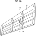
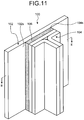
- FIG. 10 is a schematic of a conventional structure 100 of composite materials.
- FIG. 11 is an enlarged schematic of the conventional structure 100 of the composite materials.
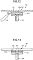
- FIG. 12 is a sectional schematic of an example of one state in a method for injecting an adhesive in manufacturing the conventional structure 100 of the composite materials.
- FIG. 13 is a sectional schematic of the conventional structure 100 of the composite materials.
- FIG. 11 is an enlarged view of an area D in FIG. 10 .
- FIGS. 12 and 13 are sectional views viewed from the E-E section in FIG. 11 .
- the conventional structure 100 of the composite materials includes an outer plate 102, a reinforcing member 104, and an adhesive 106.
- a bonding surface 104s of the reinforcing member 104 is bonded to the bonded surface 102s of the outer plate 102 with the adhesive 106 interposed therebetween.
- the adhesive 106 is provided to an area between the bonded surface 102s of the outer plate 102 and the bonding surface 104s of the reinforcing member 104 to bond the bonded surface 102s of the outer plate 102 and the bonding surface 104s of the reinforcing member 104.
- the outer plate 102 and the reinforcing member 104 need to be precisely positioned in the structure 100 of the composite materials, it is necessary to bond the outer plate 102 and the reinforcing member 104 by positioning the outer plate 102 and the reinforcing member 104 in advance and injecting the liquid adhesive 106 using an adhesive injector 122 from a gap between the bonded surface 102s of the outer plate 102 and the bonding surface 104s of the reinforcing member 104 into the area therebetween as illustrated in FIG. 12 .
- the area between the bonded surface 102s of the outer plate 102 and the bonding surface 104s of the reinforcing member 104 is referred to as an adhesive injection area.
- the gap between the bonded surface 102s of the outer plate 102 and the bonding surface 104s of the reinforcing member 104 is simply referred to as a gap.
- the adhesive 106 includes an air bubble 107 as illustrated in FIG. 13 , thereby reducing the bonding strength between the outer plate 102 and the reinforcing member 104.
- FIG. 14 is a sectional schematic of another example of one state in the method for injecting the adhesive in manufacturing a conventional structure 110 of the composite materials.
- the adhesive 106 additionally includes tapered portions 106t formed in a tapered shape extending from the reinforcing member 104 to the outer plate 102 at gap portions. If the gap portions of the adhesive 106 need to have resistance to external stress in the structure of the composite materials, it is necessary to form the tapered portions 106t at the gap portions of the injected adhesive 106 using a taper former 112, such as a taper-forming spatula, like the structure 110 of the composite material.
- a taper former 112 such as a taper-forming spatula
- the adhesive 106 includes air bubbles similarly to the conventional structure 100 of the composite materials, thereby reducing the bonding strength between the outer plate 102 and the reinforcing member 104.
- the present invention has an object to provide a method for injecting an adhesive and a structure that enable checking that no air bubble remains in an adhesive injection area when the adhesive is injected, reducing the number of air bubbles included in the adhesive, and suppressing reduction in the bonding strength between composite materials.
- an adhesive injection method is a method with the features of claim 1 for injecting an adhesive that bonds an outer plate and a reinforcing member.
- the reinforcing member has a plurality of through holes bored through the reinforcing member in a direction intersecting a bonding surface facing the outer plate.
- the adhesive injection method includes a positioning step of positioning the outer plate and the reinforcing member; a sealing material disposing step of disposing a sealing material that covers a gap between the outer plate and the reinforcing member; and an injecting step of injecting the adhesive into the through holes in order from one end to the other end of the bonding surface.
- the adhesive is injected into and fills in the through holes of the reinforcing member.
- air bubbles are removed from the other end of the bonding surface, the gap, and the through holes into which the adhesive is not injected.
- the adhesive is checked from another through hole formed adjacent to the first through hole into which the adhesive is being injected. Consequently, the configuration enables checking that no air bubble remains in an adhesive injection area when the adhesive is injected, reducing the number of air bubbles included in the adhesive, and suppressing reduction in the bonding strength between the composite materials.
- the sealing material forms the adhesive injected at the injecting step into a tapered shape tapering from the reinforcing member to the outer plate.
- This configuration can stabilize the quality of the portion formed in a tapered shape and increase the resistance to external stress at a gap portion of the adhesive.
- the configuration requires less work to form the adhesive into a tapered shape.
- the sealing material has flexibility and changes its shape in such a manner to swell toward an outside of the gap as the adhesive is injected at the injecting step.
- This configuration can form the gap portion of the adhesive into a desired tapered shape using shrinkage of the adhesive accompanying curing.
- the configuration can further stabilize the quality of the portion formed in a tapered shape.
- the sealing material is a dam member which is a rigid body and an inside of which is formed in a tapered shape tapering from the reinforcing member to the outer plate.
- This configuration can form the gap portion of the adhesive into a desired tapered shape corresponding to the inner shape of the dam member.
- the configuration can further stabilize the quality of the portion formed in a tapered shape.
- the sealing material includes a plurality of divided sealing pieces, and at the sealing material disposing step, the sealing pieces are disposed in order from the one end to the other end of the bonding surface, and before the adhesive injected at the injecting step protrudes beyond a range of a previously disposed sealing piece, a sealing piece is additionally disposed.
- This configuration can maintain the state of being capable of removing air bubbles from the other end of the bonding surface corresponding to an injection state of the adhesive.
- suction is performed through the through hole formed adjacent to the through hole, and when the adhesive is recognized through the through hole formed adjacent to the through hole into which the adhesive is being injected, a through hole through which suction is to be performed is shifted from the through hole through which the suction is being performed to another through hole formed adjacent to the through hole through which the suction is being performed.
- a lid member is attached to the through hole on which injection of the adhesive is completed. This configuration can prevent the adhesive from leaking from the through hole on which injection of the adhesive is completed.
- the lid member includes a lid body that covers the through hole; a protrusion extending in a protruding manner in a direction from the lid body toward the outer plate; and a stopper provided at a position of a predetermined length from a front end of the protrusion toward the lid body and that prevents the lid member from coming off from the through hole, and the lid member keeps the thickness of the adhesive at a length defined based on the predetermined length.
- This configuration can prevent the lid member from coming off from the through hole and keep the thickness of the adhesive at a length defined based on the predetermined length.
- the bonding surface extends in a certain direction
- the through holes are formed in a pair of two columns extending in the certain direction in a staggered manner
- the sealing material extends in the certain direction and covers the gap formed on both sides.
- the reinforcing member includes a flange extending in a direction along the bonding surface; and a web extending in a direction intersecting the bonding surface and in the certain direction, and the through holes are formed in a pair of two columns in a staggered manner with the web sandwiched therebetween.
- This configuration requires the bonding surface with a smaller area and a smaller number of through holes and can further increase the reinforcing effect of the reinforcing member.
- a structure according to the invention has the features of claim 10 and includes inter alia an outer plate; a reinforcing member; and an adhesive that bonds the outer plate and the reinforcing member.
- the reinforcing member includes a plurality of through holes bored through the reinforcing member in a direction intersecting a bonding surface facing the outer plate, and the adhesive is injected into the through holes.
- the adhesive is injected from the through holes of the reinforcing member.
- air bubbles are removed from the other end of the bonding surface, the gap, and the through holes into which the adhesive is not injected.
- the adhesive is checked through another through hole formed adjacent to the first through hole into which the adhesive is being injected. Consequently, the configuration enables checking that no air bubble remains in the adhesive injection area when the adhesive is injected, reducing the number of air bubbles included in the adhesive, and suppressing reduction in the bonding strength between the composite materials.
- the adhesive is formed in a tapered shape tapering from the reinforcing member to the outer plate.
- This configuration can stabilize the quality of the portion formed in a tapered shape and increase the resistance to external stress at the gap portion of the adhesive.
- the configuration requires less work to form the adhesive in a tapered shape.
- the structure further includes a lid member attached to the through hole, and the lid member includes a lid body that covers the through hole; a protrusion extending in a protruding manner in a direction from the lid body toward the outer plate; and a stopper provided at a position of a predetermined length from a front end of the protrusion toward the lid body and that prevents the lid member from coming off from the through hole.
- This configuration can prevent the adhesive from leaking from the through hole.
- the configuration can prevent the lid member from coming off from the through hole and keep the thickness of the adhesive at the predetermined length.
- the bonding surface extends in a certain direction, and the through holes are formed in a pair of two columns extending in the certain direction in a staggered manner.
- This configuration requires the bonding surface with a smaller area and a smaller number of through holes and can increase the reinforcing effect of the reinforcing member.
- the reinforcing member includes a flange extending in a direction along the bonding surface; and a web extending in a direction intersecting the bonding surface and in the certain direction, and the through holes are formed in a pair of two columns in a staggered manner with the web sandwiched therebetween.
- This configuration requires the bonding surface with a smaller area and a smaller number of through holes and can further increase the reinforcing effect of the reinforcing member.
- the present invention can provide a method for injecting an adhesive and a structure that enable checking that no air bubble remains in an adhesive injection area when the adhesive is injected, reducing the number of air bubbles included in the adhesive, and suppressing reduction in the bonding strength between composite materials.
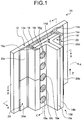
- FIG. 1 is a schematic of a structure 10 of composite materials according to a first embodiment.
- the structure 10 of the composite materials includes an outer plate 12, a reinforcing member 14, and an adhesive 16.
- an outer plate 12 To a bonded surface 12s of the outer plate 12, a bonding surface 14s of the reinforcing member 14 is bonded with the adhesive 16 interposed therebetween.
- the bonding surface 14s of the reinforcing member 14 is bonded to the bonded surface 12s of the outer plate 12 with the adhesive 16 interposed therebetween.
- the outer plate 12 and the bonded surface 12s face the reinforcing member 14 and the bonding surface 14s in a direction orthogonal to the surfaces.
- a member to be reinforced is referred to as the outer plate 12, and a member that reinforces the member to be reinforced is referred to as the reinforcing member 14 for convenience of detailed explanation.
- the combination of members bonded by the adhesive 16 is not limited thereto and may include combinations of any members having shapes capable of being bonded.
- the adhesive 16 is provided to an area between the bonded surface 12s of the outer plate 12 and the bonding surface 14s of the reinforcing member 14 to bond the bonded surface 12s of the outer plate 12 and the bonding surface 14s of the reinforcing member 14.
- the area provided with the adhesive 16 between the bonded surface 12s of the outer plate 12 and the bonding surface 14s of the reinforcing member 14 is referred to as an adhesive injection area.
- the outer plate 12 is a plate of the composite material extending in a direction along a plane including the bonded surface 12s and includes the bonded surface 12s.
- the reinforcing member 14 is a T-shaped member extending in one direction along the bonding surface 14s, that is, a Z-direction in FIG. 1 . As illustrated in FIG. 1 , the reinforcing member 14 includes a flange 15a and a web 15b. The flange 15a extends in a direction along the bonding surface 14s. The web 15b extends in a direction intersecting the bonding surface 14s and in the Z-direction.
- the reinforcing member 14 includes a member 14a, a member 14b, a member 14c, and a member 14d.
- the members 14a and 14b are L-shaped members of the composite material extending along the Z-direction.
- the member 14c is a plate of the composite material extending in a direction along a plane including the bonding surface 14s and includes the bonding surface 14s.
- the member 14d is a triangular prismatic member of the composite material extending along the Z-direction.
- a first outside surface of the member 14a forming the L-shape is bonded to a second outside surface of the member 14b forming the L-shape.
- a second outside surface of the member 14a forming the L-shape is bonded to a first part of the member 14c with respect to a center line along the Z-direction on the surface opposite to the bonding surface 14s.
- a first outside surface of the member 14b forming the L-shape is bonded to a second part of the member 14c with respect to the center line along the Z-direction on the surface opposite to the bonding surface 14s.
- the second outside surface of the member 14b forming the L-shape is bonded to the first outside surface of the member 14a forming the L-shape.
- the first part of the member 14c with respect to the center line along the Z-direction on the surface opposite to the bonding surface 14s is bonded to the second outside surface of the member 14a forming the L-shape.
- the second part of the member 14c with respect to the center line along the Z-direction on the surface opposite to the bonding surface 14s is bonded to the first outside surface of the member 14b forming the L-shape.
- the member 14d is disposed so as to fill a space formed by a curve on the outside surface of the member 14a forming the L-shape, a curve on the outside surface of the member 14b forming the L-shape, and a part of the member 14c near the center line along the Z-direction on the surface opposite to the bonding surface 14s.
- the member 14d is bonded to the members 14a, 14b, and 14c.
- the members 14a, 14b, 14c, and 14d may be bonded by curing of a resin included in the composite materials, which will be described later, or by the adhesive for bonding the composite materials.
- the flange 15a includes a part of the member 14a including the second surface forming the L-shape, a part of the member 14b including the first surface forming the L-shape, and the member 14c.
- the web 15b includes a part of the member 14a including the first surface forming the L-shape and a part of the member 14b including the second surface forming the L-shape.
- the reinforcing member 14 includes a plurality of through holes bored therethrough in a direction intersecting the bonding surface 14s.
- the through holes are a through hole 18a, a through hole 18b, a through hole 18c, a through hole 18d, a through hole 18e, a through hole 18f, a through hole 18g, a through hole 18h, a through hole 18i, and a through hole 18j (refer to FIGS. 3 and 4 on the through holes 18b, 18d, 18f, 18h, and 18j).
- the through holes 18a to 18j are formed in this order from one end of the bonding surface 14s, that is, the end in the -Z-direction in FIG. 1 to the other end of the bonding surface 14s, that is, the end in the +Z-direction in FIG. 1 .
- the through holes 18a to 18j are bored through the flange 15a included in the reinforcing member 14 in a direction orthogonal to the bonding surface 14s. More specifically, the through holes 18a, 18c, 18e, 18g, and 18i are bored through the part of the member 14a including the second surface forming the L-shape and the member 14c included in the reinforcing member 14 and are formed in a line in the direction along the Z-direction.
- the through holes 18b, 18d, 18f, 18h, and 18j are bored through the part of the member 14b including the first surface forming the L-shape and the member 14c and are formed in a line in a direction along the Z-direction.
- the through holes 18a to 18j are formed in a pair of two columns in a staggered manner with the web 15b sandwiched therebetween from the end in the -Z-direction to the end in the +Z-direction in the flange 15a.
- the through holes 18a to 18j are formed side by side successively from the end in the -Z-direction to the end in the +Z-direction.
- the through hole 18a and the through hole 18b are formed adjacent to each other
- the through hole 18b and the through hole 18c are formed adjacent to each other
- the through hole 18c and the through hole 18d are formed adjacent to each other
- the through hole 18d and the through hole 18e are formed adjacent to each other
- the through hole 18e and the through hole 18f are formed adjacent to each other
- the through hole 18f and the through hole 18g are formed adjacent to each other
- the through hole 18g and the through hole 18h are formed adjacent to each other
- the through hole 18h and the through hole 18i are formed adjacent to each other
- the through hole 18i and the through hole 18j are formed adjacent to each other.
- the adhesive 16 is injected into and fills in the through holes 18a to 18j.
- the adhesive 16 injected into and filling in the through holes 18a to 18j are integrated with the adhesive 16 in the adhesive injection area.
- the composite materials used for the structure 10, the outer plate 12, and the reinforcing member 14 are materials used for aircrafts, cars, and ships, for example.
- the composite materials include reinforcing fibers that reinforce the composite material and a resin impregnated into the reinforcing fibers, for example.
- the reinforcing fiber is a bundle of the order of several hundred to several thousand base fibers in a range of equal to or larger than 5 ⁇ m and equal to or smaller than 7 ⁇ m, for example.
- the base fibers constituting the reinforcing fibers are carbon fibers, for example.
- the base fibers constituting the reinforcing fibers are not limited thereto and may be other plastic fibers, glass fibers, or metal fibers, for example.
- the resin impregnated into the reinforcing fibers is preferably a thermosetting resin, it may be a thermoplastic resin.
- the thermosetting resin include, but are not limited to, epoxy resin, etc.
- the thermoplastic resin include, but are not limited to, polyetheretherketone (PEEK), polyetherketoneketone (PEKK), polyphenylenesulfide (PPS), etc.
- the resin impregnated into the reinforcing fibers is not limited thereto and may be other resins.
- the adhesive 16 may be any kinds of adhesive as long as it can bond the composite materials.
- the adhesive 16 is preferably integrated with the composite materials and include the resin used for the composite materials, for example. The use of the resin can increase the bonding strength between the composite materials.
- the structure 10 has a gap between the bonded surface 12s of the outer plate 12 and the bonding surface 14s of the reinforcing member 14. Through the gap, the adhesive 16 is exposed from the outer plate 12 and the reinforcing member 14.
- the gap between the bonded surface 12s of the outer plate 12 and the bonding surface 14s of the reinforcing member 14 is simply referred to as a gap.
- the gaps extend in the Z-direction on both sides of the bonding surface 14s because the outer plate 12 and the reinforcing member 14 of the structure 10 extend in the Z-direction.
- the structure 10 may include a sealing material 20 that covers the gaps formed on both sides of the bonding surface 14s.
- the sealing material 20 is disposed in a method for injecting the adhesive 16, which will be described later.
- One side of the sealing material 20 is fixed to the reinforcing member 14, and the other side thereof is fixed to the outer plate 12, thereby covering the gap.
- the sealing material 20 includes a plurality of divided pieces, that is, a sealing piece 20a, a sealing piece 20b, a sealing piece 20c, and a sealing piece 20d.
- the sealing material 20 and the sealing pieces 20a to 20d may be tape-like members made of a flexible material or dam members made of a rigid material.
- each of the sealing pieces 20a and 20c is fixed to the part of the member 14a of the reinforcing member 14 including the second surface forming the L-shape without covering the through holes 18a, 18c, 18e, 18g, and 18i.
- the sealing piece 20a and the sealing piece 20c are disposed in this order from the end in the -Z-direction to the end in the +Z-direction.
- the sealing pieces 20a and 20c cover the gap formed on one side and can be connected to and separated from each other.
- the first sides of the sealing pieces 20b and 20d are fixed to the part of the member 14b of the reinforcing member 14 including the first surface forming the L-shape without covering the through holes 18b, 18d, 18f, 18h, and 18j.
- the sealing piece 20b and the sealing piece 20d are disposed in this order from the end in the -Z-direction to the end in the +Z-direction.
- the sealing pieces 20b and 20d cover the gap formed on the other side and can be connected to and separated from each other.
- the structure 10 has the configuration described above. Because the adhesive 16 is injected into and fills in the through holes 18a to 18j of the reinforcing member 14, air bubbles are removed from the end in the +Z-direction corresponding to the other end of the bonding surface 14s, the gaps, and the through holes into which the adhesive 16 is not injected. The adhesive 16 is checked through a through hole formed adjacent to a through hole into which the adhesive 16 is being injected. Consequently, the structure 10 enables checking that no air bubble remains in the adhesive injection area when the adhesive 16 is injected, reducing the number of air bubbles included in the adhesive 16, and suppressing reduction in the bonding strength between the composite materials.
- the bonding surface 14s extends in the Z-direction, and the through holes 18a to 18j are formed in a pair of two columns extending in the Z-direction in a staggered manner. Consequently, the structure 10 requires the bonding surface 14s with a smaller area and a smaller number of through holes 18a to 18j and can increase the reinforcing effect of the reinforcing member 14.
- the through holes 18a to 18j are formed in a pair of two columns extending in the Z-direction in a staggered manner with the web 15b sandwiched therebetween in the flange 15a. Consequently, the structure 10 requires the bonding surface 14s with a smaller area and a smaller number of through holes 18a to 18j and can increase the reinforcing effect of the reinforcing member 14.
- the structure 10 includes the sealing material 20 that covers the gaps, it can protect gap portions of the adhesive 16 from the outside.
- the sealing material 20 that covers the gaps includes a plurality of divided pieces, that is, the sealing pieces 20a, 20b, 20c, and 20d. With this configuration, appropriate replacement of the sealing pieces 20a, 20b, 20c, and 20d can suitably protect the gap portions of the adhesive 16 from the outside.
- the sealing material does not necessarily have the structure of the sealing material 20 described above and may extend toward the through holes 18a to 18j. This structure is preferably employed because the through holes 18a to 18j can be covered with the part of the sealing material extending toward the through holes 18a to 18j after the adhesive 16 is injected thereinto.
- the sealing material may have through holes.
- the through holes may be formed at desired positions in the sealing material or at the boundaries between the sealing pieces constituting the sealing material, for example.
- the through holes formed in the reinforcing member 14 and the through holes formed in the sealing material are successively used to remove air bubbles, check that no air bubble remains, and inject the adhesive 16. Consequently, this structure requires a smaller number of through holes formed in the reinforcing member 14, thereby further increasing the reinforcing effect of the reinforcing member 14.
- the sealing material may have through holes, and the reinforcing member 14 may have no through hole (not according to the invention as claimed).
- the through holes formed in the sealing material are successively used to remove air bubbles, check that no air bubble remains, and inject the adhesive 16. Consequently, this structure requires no through hole formed in the reinforcing member 14, thereby further increasing the reinforcing effect of the reinforcing member 14.
- FIG. 2 is a flowchart of the method for injecting the adhesive 16 according to the first embodiment.
- FIG. 3 is a schematic configuration diagram of one state in the method for injecting the adhesive 16 according to the first embodiment.
- FIG. 4 is a schematic configuration diagram of another state in the method for injecting the adhesive 16 according to the first embodiment.
- FIGS. 3 and 4 are schematics viewed from the A-A direction in FIG. 1 . The following describes the method for injecting the adhesive 16 according to the first embodiment with reference to FIGS. 1 to 4 .
- the method for injecting the adhesive 16 includes a positioning step (Step S12), a sealing material disposing step (Step S14), and an injecting step (Step S16).
- the positions of the outer plate 12 and the reinforcing member 14 to be bonded by the adhesive 16 are determined (Step S12). Specifically, the position of the reinforcing member 14 with respect to the outer plate 12 is determined. More specifically, the positions of the bonding surface 14s of the reinforcing member 14 and the bonded surface 12s of the outer plate 12 facing the bonding surface 14s in the direction orthogonal thereto, the angle between the bonding surface 14s and the bonded surface 12s, and the space between the bonding surface 14s and the bonded surface 12s are determined. As a result, the adhesive injection area and the gaps are formed between the bonding surface 14s and the bonded surface 12s.
- Step S14 the sealing material 20 that covers the gaps is disposed (Step S14). Specifically, one side of the sealing material 20 is fixed to a predetermined position on the reinforcing member 14, and the other side thereof is fixed to a predetermined position on the outer plate 12. Other parts of the sealing material 20 are not necessarily fixed, or the whole part other than the part facing the gaps may be fixed. As a result, the adhesive injection area serves as a space with its gaps covered. As illustrated in FIG. 3 , for example, the sealing pieces 20a, 20b, 20c, and 20d are disposed at once to cover the gaps extending in the Z-direction.
- the adhesive 16 before cured is successively injected into the through holes 18a to 18j from the end in the -Z-direction to the end in the +Z-direction using an adhesive injector 22 illustrated in FIG. 4 (Step S16). Specifically, the adhesive 16 is injected into the through hole 18a formed closest to the end in the -Z-direction. Subsequently, the adhesive 16 is injected into the through hole 18b formed second closest to the end in the -Z-direction. Similarly, the adhesive 16 is injected into the through holes 18c, 18d, 18e, 18f, 18g, 18h, 18i, and 18j in order. As a result, the adhesive 16 is successively injected into the adhesive injection area from the end in the -Z-direction to the end in the +Z-direction.
- Step S16 as illustrated in FIG. 4 , while the adhesive 16 is being injected into the through hole 18a, when the adhesive 16 can be recognized through the through hole 18b formed adjacent to the through hole 18a into which the adhesive 16 is being injected, the through hole into which the adhesive 16 is to be injected is shifted from the through hole 18a to the through hole 18b.
- the stage when the adhesive 16 can be recognized through the through hole 18b indicates a stage when the adhesive 16 can be visually recognized through the through hole 18b, that is, a stage when the adhesive 16 reaches the penetrating direction of the through hole 18b.
- the stage when the adhesive 16 can be recognized through the through hole 18b may be a stage when the adhesive 16 starts protruding from the through hole 18b. At this stage, it is determined that injection of the adhesive 16 into the through hole 18a is completed.
- Step S16 the through hole into which the adhesive 16 is to be injected is shifted from the end in the -Z-direction to the end in the +Z-direction, that is, the through holes 18c, 18d, 18e, 18f, 18g, 18h, 18i, and 18j in order subsequently to the through holes 18a and 18b.
- the adhesive 16 is injected into the adhesive injection area from the end in the -Z-direction to the end in the +Z-direction.
- Step S16 when the adhesive 16 is being injected into the through hole 18a, air bubbles are removed from the gaps on the end in the +Z-direction and the through holes 18b to 18j into which the adhesive 16 is not injected.
- the adhesive 16 is being injected into the through hole 18b, air bubbles are removed from the gaps on the end in the +Z-direction and the through holes 18c to 18j into which the adhesive 16 is not injected.
- the adhesive 16 is being injected into any one of the through holes, air bubbles are removed from the gaps on the end in the +Z-direction and the through holes into which the adhesive 16 is not injected.
- the adhesive injection area is cleared of the air bubbles and filled with the adhesive 16.
- the sealing material 20 may be removed from the gaps. In this case, the sealing material 20 can be reused.
- the method for injecting the adhesive 16 according to the first embodiment has the configuration described above. Because the adhesive 16 is injected through the through holes 18a to 18j of the reinforcing member 14, air bubbles are removed from the end in the +Z-direction, the gaps, and the through holes into which the adhesive 16 is not injected. The adhesive 16 is checked through a through hole formed adjacent to a through hole into which the adhesive 16 is being injected. Consequently, the method enables checking that no air bubble remains in the adhesive injection area when the adhesive 16 is injected, reducing the number of air bubbles included in the adhesive 16, and suppressing reduction in the bonding strength between the composite materials.
- the method for injecting the adhesive 16 according to the first embodiment includes the sealing material disposing step, which is processing of disposing the sealing material 20 that covers the gaps. Consequently, the method can prevent the adhesive 16 from flowing out through the gaps, thereby precisely injecting the adhesive 16 into the adhesive injection area.
- the bonding surface 14s extends in the Z-direction, and the through holes 18a to 18j are formed in a pair of two columns extending in the Z-direction in a staggered manner. Consequently, the method requires the bonding surface 14s with a smaller area and a smaller number of through holes 18a to 18j and can increase the reinforcing effect of the reinforcing member 14.
- the through holes 18a to 18j are formed in a pair of two columns extending in the Z-direction in a staggered manner with the web 15b sandwiched therebetween in the flange 15a. Consequently, the method requires the bonding surface 14s with a smaller area and a smaller number of through holes 18a to 18j and can increase the reinforcing effect of the reinforcing member 14.
- the method for injecting the adhesive 16 according to the first embodiment may perform the processing at Step S14 corresponding to the state at Step S16.
- the sealing pieces are disposed in order from the end in the -Z-direction to the end in the +Z-direction.
- the sealing piece 20a and the sealing piece 20c are disposed in order at the gap on the first side
- the sealing piece 20b and the sealing piece 20d are disposed in order at the gap on the second side.
- the sealing pieces 20a and 20b at the end in the -Z-direction are disposed first.
- the sealing pieces 20c and 20d are additionally disposed adjacent to the sealing pieces 20a and 20b, respectively, at the end in the +Z-direction.
- the sealing pieces 20c and 20d may be added and disposed adjacent to the sealing pieces 20a and 20b, respectively, at the end in the +Z-direction. If the adhesive injection area further extends in the Z-direction, additional sealing pieces are successively added and disposed at the end in the +Z-direction corresponding to the range of the adhesive 16 injected at Step S16 reaching in the +Z-direction.
- the method for injecting the adhesive 16 according to the first embodiment does not excessively cover, with the sealing material 20, an area into which the adhesive 16 is not injected and keeps the gaps open. Consequently, the method can maintain the state of being capable of removing air bubbles from the end in the +Z-direction corresponding to an injection state of the adhesive 16.
- the method for injecting the adhesive 16 according to the first embodiment is preferably employed because the through holes 18a to 18j can be covered with the portion of the sealing material extending toward the through holes 18a to 18j after the adhesive 16 is injected thereinto at Step S16.
- the method for injecting the adhesive 16 according to the first embodiment successively uses the through holes formed in the reinforcing member 14 and the through holes formed in the sealing material to remove air bubbles, check that no air bubble remains, and inject the adhesive 16 at Step S16. Consequently, the method requires a smaller number of through holes formed in the reinforcing member 14, thereby further increasing the reinforcing effect of the reinforcing member 14.
- the method for injecting the adhesive 16 successively uses the through holes formed in the sealing material to remove air bubbles, check that no air bubble remains, and inject the adhesive 16 at Step S16. Consequently, the method requires no through hole formed in the reinforcing member 14, thereby further increasing the reinforcing effect of the reinforcing member 14.
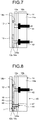
- FIG. 5 is a schematic configuration diagram of one state in the method for injecting the adhesive 16 according to a second embodiment.
- FIG. 6 is a schematic configuration diagram of a structure 30 of the composite materials and another state in the method for injecting the adhesive 16 according to the second embodiment.
- FIGS. 5 and 6 are schematics viewed from a section direction corresponding to a direction of the B-B section in FIG. 1 .
- the B-B section is a plane connecting two sections along a plane direction orthogonal to the Z-direction between the members 14a and 14b discontinuously.
- the B-B section passes through the center of the through hole 18g in the member 14a and passes through the center of the through hole 18h in the member 14b.
- the structure 30 is different from the structure 10 in that tapered portions 16t are formed at the gap portions of the adhesive 16.
- the method for injecting the adhesive 16 according to the second embodiment is different from the method for injecting the adhesive 16 according to the first embodiment in that the tapered portions 16t are formed at the gap portions of the injected adhesive 16 by the sealing material 20.
- components similar to those of the first embodiment are denoted by like reference numerals, and detailed explanation thereof is omitted.
- the structure 30 includes the outer plate 12, the reinforcing member 14, and the adhesive 16.
- the adhesive 16 has the tapered portions 16t tapering from the reinforcing member 14 to the outer plate 12 and formed at the gap portions, that is, the portions exposed from the outer plate 12 and the reinforcing member 14.
- the tapered portions 16t each cover the side surface of the flange 15a of the reinforcing member 14 on the gap side and have a tapered shape tapering from the surface of the flange 15a of the reinforcing member 14 on the web 15b side to the bonded surface 12s of the outer plate 12.
- the portions of the adhesive 16 protruding from the respective gaps serve as the tapered portions 16t having a tapered shape the thickness of which becomes thinner from the reinforcing member 14 toward the outer plate 12.
- the structure 30 may include the sealing material 20 that covers the gaps formed on both sides of the bonding surface 14s.
- the sealing material 20 included in the structure 30 extends along the tapered portions 16t.
- portions of the sealing material 20 facing the respective tapered portions 16t change their shapes to correspond to the respective tapered portions 16t in such a manner to swell into a tapered shape tapering from the reinforcing member 14 to the outer plate 12 toward the outside of the gaps.
- the sealing material 20 may change its shape in such a manner to swell into a tapered shape tapering from the reinforcing member 14 to the outer plate 12 toward the outside of the gaps while being separated from the tapered portions 16t.
- the inside portions of the sealing material 20 facing the respective tapered portions 16t are formed in a tapered shape corresponding to the respective tapered portions 16t from the reinforcing member 14 to the outer plate 12.
- the structure 30 has the configuration described above. Because the adhesive 16 includes the tapered portions 16t formed in a tapered shape tapering from the reinforcing member 14 to the outer plate 12, the structure 30 has higher resistance to external stress at the gap portions of the adhesive 16.
- the injected liquid adhesive 106 protrudes from the gaps, thereby deforming.
- the bonding strength between the outer plate 102 and the reinforcing member 104 is reduced.
- the structure 30 includes the sealing material 20, thereby suppressing protrusion of the injected adhesive 16 from the gaps and deformation of the adhesive 16. Consequently, the structure 30 can stabilize the quality of the tapered portions 16t and suppress reduction in the bonding strength between the outer plate 12 and the reinforcing member 14.
- the structure 30 requires less work to form the tapered portions 16t.
- the method for injecting the adhesive 16 according to the second embodiment includes the positioning step (Step S12), the sealing material disposing step (Step S14), and the injecting step (Step S16).
- Step S12 in the method for injecting the adhesive 16 according to the second embodiment is the same as that according to the first embodiment.
- Step S14 in the method for injecting the adhesive 16 according to the second embodiment is different from that according to the first embodiment in the way of disposing the sealing material 20 in detail. Specifically, at Step S14 in the method for injecting the adhesive 16 according to the second embodiment, one side of the sealing material 20 is fixed to a predetermined position on the reinforcing member 14, and the other side thereof is fixed to a predetermined position on the outer plate 12. In addition, other parts of the sealing material 20 are disposed so as to form the gap portions of the adhesive 16 into the tapered portions 16t.
- the sealing material 20 is a tape-like member made of a flexible material
- the parts of the sealing material 20 facing the gap portions are not fixed.
- the parts are disposed to be capable of changing their shapes in such a manner to swell into a tapered shape tapering from the reinforcing member 14 to the outer plate 12 toward the outside of the gaps as the adhesive 16 is injected.
- the inside portions of the sealing material 20 facing the gap portions are formed in a tapered shape corresponding to the respective tapered portions 16t from the reinforcing member 14 to the outer plate 12.
- Step S16 in the method for injecting the adhesive 16 according to the second embodiment is different from that according to the first embodiment in that it further includes forming the tapered portions 16t at the respective gap portions of the adhesive 16.
- the tapered portions 16t are formed at the portions of the sealing material 20 facing the respective gaps, that is, at the respective gap portions of the adhesive 16.
- the sealing material 20 is a tape-like member made of a flexible material
- the sealing material 20 changes its shape in such a manner to swell toward the outside of the gaps as illustrated in FIG. 6 from the state illustrated in FIG. 5 as the adhesive 16 is injected.
- the gap portions of the adhesive 16 swell in a protruding manner larger than the respective tapered portions 16t by the sealing material 20.
- the adhesive 16 shrinks as it cures, thereby forming the gap portions into the tapered portions 16t.
- the sealing material 20 is a dam member made of a rigid material
- the injected adhesive 16 is formed into a shape extending along the inside portion of the sealing material 20 facing the respective gap portions as illustrated in FIG. 6 . Subsequently, the adhesive 16 cures, thereby forming the gap portions into the tapered portions 16t.
- the method for injecting the adhesive 16 according to the second embodiment has the configuration described above.
- the method suppresses protrusion of the injected adhesive 16 from the gaps and deformation of the adhesive 16 with the sealing material 20. Consequently, the method can stabilize the quality of the tapered portions 16t and suppress reduction in the bonding strength between the outer plate 12 and the reinforcing member 14. In addition, the method requires less work to form the tapered portions 16t.
- the method for injecting the adhesive 16 according to the second embodiment can form the gap portions of the adhesive 16 into a desired tapered shape using shrinkage of the adhesive 16 accompanying curing.
- the method for injecting the adhesive 16 according to the second embodiment can form the gap portions of the adhesive 16 into a desired tapered shape corresponding to the shape of the inside portion of the dam member.
- FIG. 7 is a schematic configuration diagram of one state in the method for injecting the adhesive 16 according to a third embodiment.
- FIG. 8 is a schematic configuration diagram of a structure 40 of the composite materials and another state in the method for injecting the adhesive 16 according to the third embodiment.
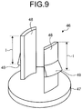
- FIG. 9 is a schematic configuration diagram of a lid member 46 included in the structure 40 of the composite materials according to the third embodiment.
- FIGS. 7 and 8 are schematics viewed from a section direction corresponding to a direction of the C-C section in FIG. 1 .
- the C-C section is a plane orthogonal to the outer plane 12 and connecting two sections along the Z-direction. One of the sections passes through the center of the through hole 18a, and the other thereof passes through the center of the through hole 18b.
- FIGS. 7 and 8 do not illustrate the area positioned in the +Z-direction with respect to the through hole 18c.
- the structure 40 is different from the structure 10 in that it further includes the lid member 46 attached to a through hole.
- the method for injecting the adhesive 16 according to the third embodiment is different from the method for injecting the adhesive 16 according to the first embodiment in that it further includes performing suction through a through hole formed adjacent to a through hole into which the adhesive 16 is being injected and attaching the lid member 46 to a through hole on which injection of the adhesive 16 is completed.
- components similar to those of the first embodiment are denoted by like reference numerals, and detailed explanation thereof is omitted.
- the structure 40 includes the outer plate 12, the reinforcing member 14, the adhesive 16, and the lid member 46.
- the lid member 46 is attached to the through hole 18a in FIG. 8 .
- the lid members 46 may be attached to all or some of the through holes 18a to 18j.
- the lid member 46 includes a lid body 47, protrusions 48, and stoppers 49.
- the lid member 46 integrates the lid body 47, the protrusions 48, and the stoppers 49 and may be made of the same material as that of the adhesive 16.
- the lid body 47 is a disc-like plate that covers a through hole and has a diameter larger than that of the through hole.
- the lid body 47 is not limited to a disk-like plate and may have any desired shape as long as it is a plate having a size large enough to sufficiently cover the through hole.
- the protrusions 48 extend in a protruding manner in a direction from the lid body 47 toward the outer plate 12.
- the stoppers 49 prevent the lid member 46 from coming off from the through hole.
- the stoppers 49 are each provided at a position of a predetermined length 1 from the front end of the protrusion 48 toward the lid body 47. As illustrated in FIG. 8 , the predetermined length 1 keeps the gap between the bonded surface 12s of the outer plate 12 and the bonding surface 14s of the reinforcing member 14, that is, the width of the adhesive injection area and the thickness of the adhesive 16 at a length defined based on the predetermined length 1.
- the predetermined length l is equal to the gap between the bonded surface 12s of the outer plate 12 and the bonding surface 14s of the reinforcing member 14, that is, the width of the adhesive injection area and the thickness of the adhesive 16.
- the relation between the predetermined length 1 and the gap between the bonded surface 12s of the outer plate 12 and the bonding surface 14s of the reinforcing member 14, that is, the width of the adhesive injection area and the thickness of the adhesive 16 is determined based on the attachment angle.
- the lid member 46 does not necessarily have the shape described above.
- the lid member may include one or a plurality of needle members provided to the lid body 47 and capable of being stuck and inserted into the injected adhesive 16.
- the needle member of the lid member preferably has a stopper that prevents the lid member from coming off from the through hole.
- the stopper is preferably provided at a position of the predetermined length 1 from the front end of the needle member toward the lid body 47.
- the lid member may include one or a plurality of spring members provided to the lid body 47 and capable of being inserted into the injected adhesive 16.
- the spring member of the lid member preferably has a stopper that prevents the lid member from coming off from the through hole.
- the stopper is preferably provided at a position of the predetermined length 1 from the front end of the spring member toward the lid body 47.
- the structure 40 has the configuration described above. Consequently, the structure 40 can prevent the adhesive 16 from leaking from the through holes to which the lid members 46 are attached. In addition, the structure 40 can prevent the lid members 46 from coming off from the through holes and keep the thickness of the adhesive 16 at a length defined based on the predetermined length 1.
- the method for injecting the adhesive 16 according to the third embodiment includes the positioning step (Step S12), the sealing material disposing step (Step S14), and the injecting step (Step S16).
- Step S12 and Step S14 in the method for injecting the adhesive 16 according to the third embodiment are the same as those according to the first embodiment.
- Step S16 in the method for injecting the adhesive 16 according to the third embodiment is different from that according to the first embodiment in that it further includes performing suction through a through hole formed adjacent to a through hole into which the adhesive 16 is being injected and attaching the lid member 46 to a through hole on which injection of the adhesive 16 is completed.
- Step S16 in the method for injecting the adhesive 16 according to the third embodiment the adhesive 16 before cured is successively injected into the through holes 18a to 18j from the end in the -Z-direction to the end in the +Z-direction using an adhesive injector 42 illustrated in FIGS. 7 and 8 .
- suction is successively performed through the through holes 18b to 18j from the end in the -Z-direction to the end in the +Z-direction with a sucker 44 illustrated in FIG. 7 .
- Step S16 in the method for injecting the adhesive 16 according to the third embodiment the adhesive 16 is injected into the through hole 18a formed closest to the end in the -Z-direction as illustrated in FIG. 7 . Simultaneously with this, suction is performed through the through hole 18b formed adjacent to the through hole 18a. At this time, only air bubbles or a mixture of the adhesive 16 and air bubbles are sucked through the through hole 18b. When the adhesive 16 with no air bubble starts to be sucked through the through hole 18b, it can be determined that the portion closer to the end in the -Z-direction than the through hole 18b is filled with the adhesive 16.
- the adhesive 16 can be recognized through the through hole 18b formed adjacent to the through hole 18a into which the adhesive 16 is being injected when the adhesive 16 is being injected into the through hole 18a. In other words, it is determined that injection of the adhesive 16 into the through hole 18a is completed.
- the through hole into which the adhesive 16 is to be injected is shifted from the through hole 18a to the through hole 18b. Simultaneously with this, the through hole through which suction is to be performed is shifted from the through hole 18b to the through hole 18c.
- the lid member 46 is attached to the through hole 18a on which injection of the adhesive 16 is completed after the through hole into which the adhesive 16 is to be injected is shifted from the through hole 18a to the through hole 18b and before the adhesive 16 sufficiently cures.
- the through hole into which the adhesive 16 is to be injected is shifted from the end in the -Z-direction to the end in the +Z-direction, that is, the through holes 18c, 18d, 18e, 18f, 18g, 18h, and 18i in order subsequently to the through holes 18a and 18b.
- the through hole through which suction is to be performed is shifted from the end in the -Z-direction to the end in the +Z-direction, that is, the through holes 18d, 18e, 18f, 18g, 18h, 18i, and 18j in order subsequently to the through holes 18b and 18c.
- the lid members 46 are successively attached to the through holes 18b to 18i on which injection of the adhesive 16 is completed.
- Step S16 in the method for injecting the adhesive 16 according to the third embodiment when injection of the adhesive 16 into the through hole 18i is completed, the through hole into which the adhesive 16 is to be injected is shifted to the through hole 18j, and suction performed through the through hole is finished.
- Step S16 in the method for injecting the adhesive 16 according to the third embodiment is finished. As a result, the adhesive 16 is injected into the adhesive injection area from the end in the -Z-direction to the end in the +Z-direction.
- Step S16 in the method for injecting the adhesive 16 according to the third embodiment when the adhesive 16 is being injected into the through hole 18a, air bubbles are removed from the gaps on the end in the +Z-direction and the through holes 18c to 18j into which the adhesive 16 is not injected. In addition, the air bubbles are actively sucked and removed through the through hole 18b.
- the adhesive 16 is being injected into the through hole 18b, air bubbles are removed from the gaps on the end in the +Z-direction and the through holes 18d to 18j into which the adhesive 16 is not injected. In addition, the air bubbles are actively sucked and removed through the through hole 18c.
- the lid members 46 may be attached to all or some of the through holes 18a to 18j.
- the lid member 46 is attached to at least one through hole. Consequently, the method can prevent the adhesive 16 from leaking from the through holes to which the lid members 46 are attached. In addition, the method can prevent the lid members 46 from coming off from the through holes and keep the thickness of the adhesive 16 at the predetermined length l.
- the method for injecting the adhesive 16 according to the third embodiment has the configuration described above.
- the adhesive 16 is checked based on the state of suction performed through a through hole formed adjacent to a through hole into which the adhesive 16 is being injected. Consequently, the method enables checking that no air bubble remains in the adhesive injection area when the adhesive 16 is injected. Furthermore, air bubbles are removed by suction. Consequently, the method enables further reducing the number of air bubbles included in the adhesive 16 and suppressing reduction in the bonding strength between the composite materials.
- the lid member 46 is attached to a through hole on which injection of the adhesive 16 is completed. Consequently, the method can prevent the adhesive 16 from leaking from the through hole on which injection of the adhesive 16 is completed.
- the lid member 46 attached to a through hole on which injection of the adhesive 16 is completed has the stoppers 49. Consequently, the method can prevent the lid member 46 from coming off from the through hole.
- the stoppers 49 are each provided at a position of the predetermined length 1 from the front end of the protrusion 48 toward the lid body 47 in the lid member 46 attached to the through hole on which injection of the adhesive 16 is completed. Consequently, the method can keep the thickness of the adhesive 16 at a length defined based on the predetermined length l.
Landscapes
- Engineering & Computer Science (AREA)
- Mechanical Engineering (AREA)
- Chemical & Material Sciences (AREA)
- Composite Materials (AREA)
- Standing Axle, Rod, Or Tube Structures Coupled By Welding, Adhesion, Or Deposition (AREA)
- Adhesives Or Adhesive Processes (AREA)
- Lining Or Joining Of Plastics Or The Like (AREA)
- Media Introduction/Drainage Providing Device (AREA)
Claims (13)
- Ein Klebstoffinjektionsverfahren zum Einspritzen eines Klebstoffs (16), der eine äußere Platte (12) und ein Verstärkungselement (14) verbindet, wobei das Verstärkungselement (14) eine Vielzahl von Durchgangslöchern (18a-j) aufweist, die durch das Verstärkungselement (14) in einer Richtung gebohrt sind, die eine Verbindungsoberfläche (14s) schneidet, wobei die Verbindungsoberfläche (14s) der äußeren Platte (12) zugewandt ist und sich in einer bestimmten Richtung erstreckt, wobei das Klebstoffinjektionsverfahren umfasst:einen Positionierungsschritt (S12) zum Positionieren der äußeren Platte (12) und des Verstärkungselements (14),einen Dichtungsmaterial-Anordnungsschritt (S14) zum Anordnen eines Dichtungsmaterials (20), das sich in der bestimmten Richtung erstreckt und einen Zwischenraum abdeckt, der zwischen der äußeren Platte (12) und dem Verstärkungselement (14) auf beiden Seiten der Verbindungsoberfläche (14s) gebildet ist, undeinen Injektionsschritt (S16) zum Einspritzen des Klebstoffs (16) in die Durchgangslöcher (18a-j) in der Reihenfolge von einem Ende zum anderen Ende der Verbindungsoberfläche (14s), wobeibei dem Injektionsschritt (S16), während der Klebstoff (16) in eines der Durchgangslöcher (18a-j) eingespritzt wird, wenn der Klebstoff (16) durch ein anderes der Durchgangslöcher (18a-j) erkannt wird, das benachbart zu dem einen Durchgangsloch (18a) ausgebildet ist, in das der Klebstoff (16) eingespritzt wird, die Reihenfolge der Durchgangslöcher (18a-j), in die der Klebstoff (16) eingespritzt werden soll, von dem einen Durchgangsloch (18a), in das der Klebstoff (16) eingespritzt wird, zu dem anderen Durchgangsloch (18b) verschoben wird,dadurch gekennzeichnet, dassdie Durchgangslöcher (18a-j) in einem Paar von zwei Spalten ausgebildet sind, die sich in der bestimmten Richtung versetzt erstrecken.
- Das Klebstoffinjektionsverfahren nach Anspruch 1, wobei das Dichtungsmaterial (20) den Klebstoff (16) bildet, der bei dem Injektionsschritt (S16) in eine sich vom Verstärkungselement (14) zur Außenplatte (12) verjüngende Form eingespritzt wird.
- Das Klebstoffinjektionsverfahren nach Anspruch 2, wobei das Dichtungsmaterial (20) flexibel ist und seine Form derart ändert, dass es zu einer Außenseite des Zwischenraums hin ausbaucht, wenn der Klebstoff (16) beim Injektionsschritt (S16) eingespritzt wird.
- Das Klebstoffinjektionsverfahren nach Anspruch 2, wobei das Dichtungsmaterial (20) ein Dammelement ist, das ein starrer Körper ist und dessen Innenseite in einer sich von dem Verstärkungselement (14) zur Außenplatte (12) hin verjüngenden Form ausgebildet ist.
- Das Klebstoffinjektionsverfahren nach einem der Ansprüche 1 bis 4, wobei
das Dichtungsmaterial (20) eine Vielzahl von unterteilten Dichtungsstücken (20a-d) umfasst, und
bei dem Dichtungsmaterial-Anordnungsschritt (S14),
die Dichtungsstücke (20a-d) in der Reihenfolge von einem Ende zum anderen Ende der Verbindungsoberfläche (14s) angeordnet werden, und
bevor der in dem Injektionsschritt (S16) eingespritzte Klebstoff (16) über einen Bereich eines zuvor angeordneten Dichtungsstücks (20a-d) hinausragt, zusätzlich ein Dichtungsstück (20a-d) angeordnet wird. - Das Klebstoffinjektionsverfahren nach einem der Ansprüche 1 bis 5, wobei bei dem Injektionsschritt (S16)
ein Absaugen durch das andere Durchgangsloch (18b) erfolgt, das neben dem einen Durchgangsloch (18a) ausgebildet ist, und
wenn der Klebstoff (16) durch das andere Durchgangsloch erkannt wird, das angrenzend an das eine Durchgangsloch (18a) ausgebildet ist, in das der Klebstoff (16) eingespritzt wird, das Durchgangsloch, durch das angesaugt werden soll, von dem anderen Durchgangsloch (18b), durch das angesaugt wird, zu einem noch anderen Durchgangsloch (18c) der Durchgangslöcher (18a-j) verschoben wird, das angrenzend an das andere Durchgangsloch (18b) ausgebildet ist, durch das angesaugt wird. - Das Klebstoffinjektionsverfahren nach einem der Ansprüche 1 bis 6, wobei bei dem Injektionsschritt (S16) ein Deckelelement (46) an dem Durchgangsloch (18a-j) angebracht wird, an dem die Injektion des Klebstoffs (16) abgeschlossen ist.
- Das Klebstoffinjektionsverfahren nach Anspruch 7, wobei
das Deckelteil (46) umfasst:einem Deckelkörper (47), der das Durchgangsloch (18a-j) abdeckt,einen Vorsprung (48), der sich in einer vorstehenden Weise in einer Richtung von dem Deckelkörper (47) zu der äußeren Platte (12) hin erstreckt, undeinen Stopper (49), der an einer Position mit einer vorbestimmten Länge (l) von einem vorderen Ende des Vorsprungs (48) in Richtung des Deckelkörpers (47) vorgesehen ist und der verhindert, dass sich das Deckelelement (46) aus dem Durchgangsloch (18a-j) löst, unddas Deckelelement (46) die Dicke des Klebstoffs (16) auf einer Länge hält, die auf der Grundlage der vorbestimmten Länge (l) definiert ist. - Das Klebstoffinjektionsverfahren nach einem der Ansprüche 1 bis 8, wobei
das Verstärkungselement (14) umfasst:einem Flansch (15a), der sich in einer Richtung entlang der Verbindungsoberfläche (14s) erstreckt, undeinen Steg (15b), der sich in einer die Verbindungsoberfläche (14s) schneidenden Richtung und in der bestimmten Richtung erstreckt, unddie Durchgangslöcher (18a-j) sind in dem Paar von zwei Spalten in versetzter Weise mit dem Steg (15b) dazwischen angeordnet. - Eine Struktur (10;30;40) umfassend:eine äußere Platte (12),ein Verstärkungselement (14), undeinen Klebstoff (16), der die äußere Platte (12) und das Verstärkungselement (14) verbindet, wobeidas Verstärkungselement (14) eine Vielzahl von Durchgangslöchern (18a-j) aufweist, die durch das Verstärkungselement (14) in einer Richtung gebohrt sind, die eine Verbindungsoberfläche (14s) schneidet, wobei die Verbindungsoberfläche (14s) der äußeren Platte (12) zugewandt ist und sich in einer bestimmten Richtung erstreckt, undder Klebstoff (16) in die Durchgangslöcher (18a-j) eingespritzt ist,dadurch gekennzeichnet, dassdie Durchgangslöcher (18a-j) in einem Paar von zwei Spalten ausgebildet sind, die sich in der bestimmten Richtung versetzt erstrecken.
- Die Struktur (30) nach Anspruch 10, wobei der Klebstoff (16) in einer sich verjüngenden Form ausgebildet ist, die sich von dem Verstärkungselement (14) zu der äußeren Platte (12) hin verjüngt.
- Die Struktur nach Anspruch 10 oder 11, weiter umfassend:ein Deckelelement (46), das an dem Durchgangsloch (18a-j) befestigt ist, wobeidas Deckelteil (46) umfasst:einem Deckelkörper (47), der das Durchgangsloch (18a-j) abdeckt,einen Vorsprung (48), der sich in einer vorstehenden Weise in einer Richtung vom Deckelkörper (47) zu der äußeren Platte (12) hin erstreckt, undeinen Stopper (49), der an einer Position mit einer vorbestimmten Länge (l) von einem vorderen Ende des Vorsprungs (48) in Richtung des Deckelkörpers (47) vorgesehen ist und der verhindert, dass sich das Deckelelement (46) aus dem Durchgangsloch (18a-j) löst.
- Die Struktur nach Anspruch 10, 11 oder 12, wobei
das Verstärkungselement (14) umfasst:einem Flansch (15a), der sich in einer Richtung entlang der Verbindungsoberfläche (14s) erstreckt, undeinen Steg (15b), der sich in einer die Verbindungsoberfläche (14s) schneidenden Richtung und in der bestimmten Richtung erstreckt, unddie Durchgangslöcher (18a-j) in dem Paar von zwei Spalten in versetzter Weise mit dem Steg (15b) dazwischen angeordnet sind.
Applications Claiming Priority (2)
| Application Number | Priority Date | Filing Date | Title |
|---|---|---|---|
| JP2016226998A JP6782616B2 (ja) | 2016-11-22 | 2016-11-22 | 接着剤の注入方法及び構造体 |
| PCT/JP2017/037419 WO2018096836A1 (ja) | 2016-11-22 | 2017-10-16 | 接着剤の注入方法及び構造体 |
Publications (3)
| Publication Number | Publication Date |
|---|---|
| EP3495119A1 EP3495119A1 (de) | 2019-06-12 |
| EP3495119A4 EP3495119A4 (de) | 2019-08-28 |
| EP3495119B1 true EP3495119B1 (de) | 2020-12-02 |
Family
ID=62195479
Family Applications (1)
| Application Number | Title | Priority Date | Filing Date |
|---|---|---|---|
| EP17873987.6A Active EP3495119B1 (de) | 2016-11-22 | 2017-10-16 | Klebstoffinjektionsverfahren und struktur |
Country Status (5)
| Country | Link |
|---|---|
| US (1) | US11305495B2 (de) |
| EP (1) | EP3495119B1 (de) |
| JP (1) | JP6782616B2 (de) |
| CN (1) | CN109715375A (de) |
| WO (1) | WO2018096836A1 (de) |
Families Citing this family (4)
| Publication number | Priority date | Publication date | Assignee | Title |
|---|---|---|---|---|
| CN108819271B (zh) * | 2018-07-30 | 2023-12-01 | 上海蓝恩控制系统有限公司 | 一种护套粘结机 |
| JP2021041375A (ja) * | 2019-09-13 | 2021-03-18 | 株式会社東芝 | 導電性流体用吐出ヘッド |
| CN110774598B (zh) * | 2019-11-12 | 2024-02-20 | 广东和胜新能源科技有限公司 | 一种电池托盘自动塞胶装置及塞胶方法 |
| EP4015196A1 (de) * | 2020-12-17 | 2022-06-22 | The Boeing Company | Systeme und verfahren zum abdichten eines verbindungshohlraums zwischen bauteilen |
Family Cites Families (16)
| Publication number | Priority date | Publication date | Assignee | Title |
|---|---|---|---|---|
| DE1594036C2 (de) | 1966-04-05 | 1982-09-23 | Hilti AG, 9494 Schaan | Einklebbares Befestigungselement |
| JPS59212250A (ja) * | 1983-05-17 | 1984-12-01 | 三菱電機株式会社 | サ−マルインシユレ−タの製造方法 |
| JPS6078131A (ja) * | 1983-10-03 | 1985-05-02 | Mitsubishi Heavy Ind Ltd | 構造物用複合部材の製造方法 |
| US5229204A (en) | 1992-02-28 | 1993-07-20 | Armorvision Plastics & Glass | Bullet-resistant transparent panel, and method and press for making same |
| CA2131011A1 (en) * | 1992-02-28 | 1993-09-02 | Joseph Labock | Bullet-resistant transparent panel, and method and press for making same |
| JP4856327B2 (ja) | 2001-07-03 | 2012-01-18 | 富士重工業株式会社 | 複合材パネルの製造方法 |
| JP3851182B2 (ja) * | 2002-02-06 | 2006-11-29 | トヨタ紡織株式会社 | 重ね結合されたボード製品およびその結合方法 |
| US7645406B2 (en) * | 2005-04-21 | 2010-01-12 | The Boeing Company | Adhesive injection process for Pi-joint assemblies |
| NO20072738L (no) * | 2007-05-30 | 2008-12-01 | Mirador As | Kobling og fremgangsmate for sammenfoyning |
| US8933325B2 (en) * | 2010-01-21 | 2015-01-13 | Kyocera Corporation | Solar cell module |
| CN102469730B (zh) * | 2010-11-16 | 2014-08-20 | 富泰华工业(深圳)有限公司 | 粘接组件及其粘接方法 |
| JP2012220023A (ja) | 2011-04-13 | 2012-11-12 | Nbl Technovator Co Ltd | Frp高圧管接着継ぎ手の構造 |
| JP2012237381A (ja) * | 2011-05-12 | 2012-12-06 | Nifco Inc | ホールプラグ |
| FR2980251B1 (fr) * | 2011-09-16 | 2014-08-22 | Daher Aerospace | Procede pour l'assemblage d'une structure dite caisson et structure obtenue par un tel procede |
| US9555608B2 (en) * | 2013-02-22 | 2017-01-31 | The Boeing Company | System and method of forming an injection-bonded joint |
| DE102015002262A1 (de) * | 2014-02-27 | 2015-08-27 | Imperia Gesellschaft für angewandte Fahrzeugentwicklung mbH | Verfahren zur Herstellung eines Leichtbauteils |
-
2016
- 2016-11-22 JP JP2016226998A patent/JP6782616B2/ja active Active
-
2017
- 2017-10-16 US US16/332,155 patent/US11305495B2/en active Active
- 2017-10-16 EP EP17873987.6A patent/EP3495119B1/de active Active
- 2017-10-16 CN CN201780056544.1A patent/CN109715375A/zh active Pending
- 2017-10-16 WO PCT/JP2017/037419 patent/WO2018096836A1/ja not_active Ceased
Non-Patent Citations (1)
| Title |
|---|
| None * |
Also Published As
| Publication number | Publication date |
|---|---|
| JP2018083325A (ja) | 2018-05-31 |
| EP3495119A4 (de) | 2019-08-28 |
| JP6782616B2 (ja) | 2020-11-11 |
| US11305495B2 (en) | 2022-04-19 |
| WO2018096836A1 (ja) | 2018-05-31 |
| CN109715375A (zh) | 2019-05-03 |
| US20190202139A1 (en) | 2019-07-04 |
| EP3495119A1 (de) | 2019-06-12 |
Similar Documents
| Publication | Publication Date | Title |
|---|---|---|
| EP3495119B1 (de) | Klebstoffinjektionsverfahren und struktur | |
| US9555608B2 (en) | System and method of forming an injection-bonded joint | |
| CN109070500B (zh) | 用于制备复合层合物的设备和方法 | |
| US20150151485A1 (en) | Method of fastening structural metal reinforcement on a portion of a gas turbine blade made of composite material, and an injection mold for performing such a method | |
| US9475586B2 (en) | Method for sealing a fuel tank | |
| US9073267B1 (en) | Method of assembling panels and adhesively bonded joints used therein | |
| US8220131B2 (en) | Assembly of aircraft components | |
| KR20200091456A (ko) | 일측에 부착된 유지 부재(retaining element)를 갖는 차량 측면창 | |
| US8551383B2 (en) | Method for the localized working of a structural component at a working location | |
| CN107923426A (zh) | 用于制造组件的方法 | |
| EP3947959B1 (de) | Anordnung, verfahren und werkzeug zum befestigen von bauteilen | |
| US11046028B2 (en) | Method for molding composite material | |
| CA2987171C (en) | Honeycomb core sandwich panels | |
| EP4353460B1 (de) | Verfahren und struktureller lückenfüller für one-up-anordnung | |
| US20210001570A1 (en) | Bonding process and system | |
| US9815419B2 (en) | Trim panel | |
| US20130333295A1 (en) | Attachment Structure for Window Glass | |
| EP4442441A1 (de) | Verfahren zur in-situ-herstellung einer schutzauskleidung auf einem länglichen strukturteil eines flugzeugs | |
| US20240335986A1 (en) | Method for protecting a profile structural part of an aircraft against mechanical wear and/or mechanical impact | |
| KR102367031B1 (ko) | 복합재 구조물 제조방법 및 이를 이용하여 제조된 복합재 구조물 | |
| US20240351298A1 (en) | Assembly structure and process for manufacturing a composite part with controlled geometry | |
| KR20130143513A (ko) | 부품 비틀림을 보상하기 위한 사출 성형 컴포넌트 | |
| EP2781345A1 (de) | Verfahren und System zur Herstellung von Verbundstrukturen | |
| JP2019098591A (ja) | 樹脂材の製造装置及び製造方法 | |
| JP4727293B2 (ja) | 膜モジュール及びその製造方法 |
Legal Events
| Date | Code | Title | Description |
|---|---|---|---|
| STAA | Information on the status of an ep patent application or granted ep patent |
Free format text: STATUS: THE INTERNATIONAL PUBLICATION HAS BEEN MADE |
|
| PUAI | Public reference made under article 153(3) epc to a published international application that has entered the european phase |
Free format text: ORIGINAL CODE: 0009012 |
|
| STAA | Information on the status of an ep patent application or granted ep patent |
Free format text: STATUS: REQUEST FOR EXAMINATION WAS MADE |
|
| 17P | Request for examination filed |
Effective date: 20190308 |
|
| AK | Designated contracting states |
Kind code of ref document: A1 Designated state(s): AL AT BE BG CH CY CZ DE DK EE ES FI FR GB GR HR HU IE IS IT LI LT LU LV MC MK MT NL NO PL PT RO RS SE SI SK SM TR |
|
| AX | Request for extension of the european patent |
Extension state: BA ME |
|
| REG | Reference to a national code |
Ref country code: DE Ref legal event code: R079 Ref document number: 602017029042 Country of ref document: DE Free format text: PREVIOUS MAIN CLASS: B29C0065520000 Ipc: B29C0065540000 |
|
| A4 | Supplementary search report drawn up and despatched |
Effective date: 20190731 |
|
| RIC1 | Information provided on ipc code assigned before grant |
Ipc: B29C 65/00 20060101ALI20190725BHEP Ipc: B29C 70/02 20060101ALI20190725BHEP Ipc: B29C 65/54 20060101AFI20190725BHEP |
|
| DAV | Request for validation of the european patent (deleted) | ||
| DAX | Request for extension of the european patent (deleted) | ||
| GRAP | Despatch of communication of intention to grant a patent |
Free format text: ORIGINAL CODE: EPIDOSNIGR1 |
|
| STAA | Information on the status of an ep patent application or granted ep patent |
Free format text: STATUS: GRANT OF PATENT IS INTENDED |
|
| INTG | Intention to grant announced |
Effective date: 20200430 |
|
| GRAS | Grant fee paid |
Free format text: ORIGINAL CODE: EPIDOSNIGR3 |
|
| RIN1 | Information on inventor provided before grant (corrected) |
Inventor name: KAMO, SOTA Inventor name: YOSHINO, KATSUYA Inventor name: KATO, TETSUYA Inventor name: TAKAGI, KIYOKA Inventor name: ISHIDA, JUN |
|
| GRAA | (expected) grant |
Free format text: ORIGINAL CODE: 0009210 |
|
| STAA | Information on the status of an ep patent application or granted ep patent |
Free format text: STATUS: THE PATENT HAS BEEN GRANTED |
|
| AK | Designated contracting states |
Kind code of ref document: B1 Designated state(s): AL AT BE BG CH CY CZ DE DK EE ES FI FR GB GR HR HU IE IS IT LI LT LU LV MC MK MT NL NO PL PT RO RS SE SI SK SM TR |
|
| REG | Reference to a national code |
Ref country code: GB Ref legal event code: FG4D |
|
| REG | Reference to a national code |
Ref country code: AT Ref legal event code: REF Ref document number: 1340431 Country of ref document: AT Kind code of ref document: T Effective date: 20201215 Ref country code: CH Ref legal event code: EP |
|
| REG | Reference to a national code |
Ref country code: IE Ref legal event code: FG4D |
|
| REG | Reference to a national code |
Ref country code: DE Ref legal event code: R096 Ref document number: 602017029042 Country of ref document: DE |
|
| PG25 | Lapsed in a contracting state [announced via postgrant information from national office to epo] |
Ref country code: FI Free format text: LAPSE BECAUSE OF FAILURE TO SUBMIT A TRANSLATION OF THE DESCRIPTION OR TO PAY THE FEE WITHIN THE PRESCRIBED TIME-LIMIT Effective date: 20201202 Ref country code: RS Free format text: LAPSE BECAUSE OF FAILURE TO SUBMIT A TRANSLATION OF THE DESCRIPTION OR TO PAY THE FEE WITHIN THE PRESCRIBED TIME-LIMIT Effective date: 20201202 Ref country code: GR Free format text: LAPSE BECAUSE OF FAILURE TO SUBMIT A TRANSLATION OF THE DESCRIPTION OR TO PAY THE FEE WITHIN THE PRESCRIBED TIME-LIMIT Effective date: 20210303 Ref country code: NO Free format text: LAPSE BECAUSE OF FAILURE TO SUBMIT A TRANSLATION OF THE DESCRIPTION OR TO PAY THE FEE WITHIN THE PRESCRIBED TIME-LIMIT Effective date: 20210302 |
|
| REG | Reference to a national code |
Ref country code: NL Ref legal event code: MP Effective date: 20201202 |
|
| REG | Reference to a national code |
Ref country code: AT Ref legal event code: MK05 Ref document number: 1340431 Country of ref document: AT Kind code of ref document: T Effective date: 20201202 |
|
| PG25 | Lapsed in a contracting state [announced via postgrant information from national office to epo] |
Ref country code: LV Free format text: LAPSE BECAUSE OF FAILURE TO SUBMIT A TRANSLATION OF THE DESCRIPTION OR TO PAY THE FEE WITHIN THE PRESCRIBED TIME-LIMIT Effective date: 20201202 Ref country code: PL Free format text: LAPSE BECAUSE OF FAILURE TO SUBMIT A TRANSLATION OF THE DESCRIPTION OR TO PAY THE FEE WITHIN THE PRESCRIBED TIME-LIMIT Effective date: 20201202 Ref country code: SE Free format text: LAPSE BECAUSE OF FAILURE TO SUBMIT A TRANSLATION OF THE DESCRIPTION OR TO PAY THE FEE WITHIN THE PRESCRIBED TIME-LIMIT Effective date: 20201202 Ref country code: BG Free format text: LAPSE BECAUSE OF FAILURE TO SUBMIT A TRANSLATION OF THE DESCRIPTION OR TO PAY THE FEE WITHIN THE PRESCRIBED TIME-LIMIT Effective date: 20210302 |
|
| PG25 | Lapsed in a contracting state [announced via postgrant information from national office to epo] |
Ref country code: NL Free format text: LAPSE BECAUSE OF FAILURE TO SUBMIT A TRANSLATION OF THE DESCRIPTION OR TO PAY THE FEE WITHIN THE PRESCRIBED TIME-LIMIT Effective date: 20201202 Ref country code: HR Free format text: LAPSE BECAUSE OF FAILURE TO SUBMIT A TRANSLATION OF THE DESCRIPTION OR TO PAY THE FEE WITHIN THE PRESCRIBED TIME-LIMIT Effective date: 20201202 |
|
| REG | Reference to a national code |
Ref country code: LT Ref legal event code: MG9D |
|
| PG25 | Lapsed in a contracting state [announced via postgrant information from national office to epo] |
Ref country code: SK Free format text: LAPSE BECAUSE OF FAILURE TO SUBMIT A TRANSLATION OF THE DESCRIPTION OR TO PAY THE FEE WITHIN THE PRESCRIBED TIME-LIMIT Effective date: 20201202 Ref country code: PT Free format text: LAPSE BECAUSE OF FAILURE TO SUBMIT A TRANSLATION OF THE DESCRIPTION OR TO PAY THE FEE WITHIN THE PRESCRIBED TIME-LIMIT Effective date: 20210405 Ref country code: RO Free format text: LAPSE BECAUSE OF FAILURE TO SUBMIT A TRANSLATION OF THE DESCRIPTION OR TO PAY THE FEE WITHIN THE PRESCRIBED TIME-LIMIT Effective date: 20201202 Ref country code: SM Free format text: LAPSE BECAUSE OF FAILURE TO SUBMIT A TRANSLATION OF THE DESCRIPTION OR TO PAY THE FEE WITHIN THE PRESCRIBED TIME-LIMIT Effective date: 20201202 Ref country code: CZ Free format text: LAPSE BECAUSE OF FAILURE TO SUBMIT A TRANSLATION OF THE DESCRIPTION OR TO PAY THE FEE WITHIN THE PRESCRIBED TIME-LIMIT Effective date: 20201202 Ref country code: EE Free format text: LAPSE BECAUSE OF FAILURE TO SUBMIT A TRANSLATION OF THE DESCRIPTION OR TO PAY THE FEE WITHIN THE PRESCRIBED TIME-LIMIT Effective date: 20201202 Ref country code: LT Free format text: LAPSE BECAUSE OF FAILURE TO SUBMIT A TRANSLATION OF THE DESCRIPTION OR TO PAY THE FEE WITHIN THE PRESCRIBED TIME-LIMIT Effective date: 20201202 |
|
| PG25 | Lapsed in a contracting state [announced via postgrant information from national office to epo] |
Ref country code: AT Free format text: LAPSE BECAUSE OF FAILURE TO SUBMIT A TRANSLATION OF THE DESCRIPTION OR TO PAY THE FEE WITHIN THE PRESCRIBED TIME-LIMIT Effective date: 20201202 |
|
| REG | Reference to a national code |
Ref country code: DE Ref legal event code: R097 Ref document number: 602017029042 Country of ref document: DE |
|
| PG25 | Lapsed in a contracting state [announced via postgrant information from national office to epo] |
Ref country code: IS Free format text: LAPSE BECAUSE OF FAILURE TO SUBMIT A TRANSLATION OF THE DESCRIPTION OR TO PAY THE FEE WITHIN THE PRESCRIBED TIME-LIMIT Effective date: 20210402 |
|
| PLBE | No opposition filed within time limit |
Free format text: ORIGINAL CODE: 0009261 |
|
| STAA | Information on the status of an ep patent application or granted ep patent |
Free format text: STATUS: NO OPPOSITION FILED WITHIN TIME LIMIT |
|
| PG25 | Lapsed in a contracting state [announced via postgrant information from national office to epo] |
Ref country code: AL Free format text: LAPSE BECAUSE OF FAILURE TO SUBMIT A TRANSLATION OF THE DESCRIPTION OR TO PAY THE FEE WITHIN THE PRESCRIBED TIME-LIMIT Effective date: 20201202 Ref country code: IT Free format text: LAPSE BECAUSE OF FAILURE TO SUBMIT A TRANSLATION OF THE DESCRIPTION OR TO PAY THE FEE WITHIN THE PRESCRIBED TIME-LIMIT Effective date: 20201202 |
|
| 26N | No opposition filed |
Effective date: 20210903 |
|
| PG25 | Lapsed in a contracting state [announced via postgrant information from national office to epo] |
Ref country code: DK Free format text: LAPSE BECAUSE OF FAILURE TO SUBMIT A TRANSLATION OF THE DESCRIPTION OR TO PAY THE FEE WITHIN THE PRESCRIBED TIME-LIMIT Effective date: 20201202 Ref country code: SI Free format text: LAPSE BECAUSE OF FAILURE TO SUBMIT A TRANSLATION OF THE DESCRIPTION OR TO PAY THE FEE WITHIN THE PRESCRIBED TIME-LIMIT Effective date: 20201202 |
|
| PG25 | Lapsed in a contracting state [announced via postgrant information from national office to epo] |
Ref country code: ES Free format text: LAPSE BECAUSE OF FAILURE TO SUBMIT A TRANSLATION OF THE DESCRIPTION OR TO PAY THE FEE WITHIN THE PRESCRIBED TIME-LIMIT Effective date: 20201202 |
|
| REG | Reference to a national code |
Ref country code: CH Ref legal event code: PL |
|
| PG25 | Lapsed in a contracting state [announced via postgrant information from national office to epo] |
Ref country code: IS Free format text: LAPSE BECAUSE OF FAILURE TO SUBMIT A TRANSLATION OF THE DESCRIPTION OR TO PAY THE FEE WITHIN THE PRESCRIBED TIME-LIMIT Effective date: 20210402 |
|
| REG | Reference to a national code |
Ref country code: BE Ref legal event code: MM Effective date: 20211031 |
|
| PG25 | Lapsed in a contracting state [announced via postgrant information from national office to epo] |
Ref country code: MC Free format text: LAPSE BECAUSE OF FAILURE TO SUBMIT A TRANSLATION OF THE DESCRIPTION OR TO PAY THE FEE WITHIN THE PRESCRIBED TIME-LIMIT Effective date: 20201202 |
|
| PG25 | Lapsed in a contracting state [announced via postgrant information from national office to epo] |
Ref country code: LU Free format text: LAPSE BECAUSE OF NON-PAYMENT OF DUE FEES Effective date: 20211016 Ref country code: BE Free format text: LAPSE BECAUSE OF NON-PAYMENT OF DUE FEES Effective date: 20211031 |
|
| PG25 | Lapsed in a contracting state [announced via postgrant information from national office to epo] |
Ref country code: LI Free format text: LAPSE BECAUSE OF NON-PAYMENT OF DUE FEES Effective date: 20211031 Ref country code: CH Free format text: LAPSE BECAUSE OF NON-PAYMENT OF DUE FEES Effective date: 20211031 |
|
| PG25 | Lapsed in a contracting state [announced via postgrant information from national office to epo] |
Ref country code: IE Free format text: LAPSE BECAUSE OF NON-PAYMENT OF DUE FEES Effective date: 20211016 |
|
| PG25 | Lapsed in a contracting state [announced via postgrant information from national office to epo] |
Ref country code: CY Free format text: LAPSE BECAUSE OF FAILURE TO SUBMIT A TRANSLATION OF THE DESCRIPTION OR TO PAY THE FEE WITHIN THE PRESCRIBED TIME-LIMIT Effective date: 20201202 |
|
| PG25 | Lapsed in a contracting state [announced via postgrant information from national office to epo] |
Ref country code: HU Free format text: LAPSE BECAUSE OF FAILURE TO SUBMIT A TRANSLATION OF THE DESCRIPTION OR TO PAY THE FEE WITHIN THE PRESCRIBED TIME-LIMIT; INVALID AB INITIO Effective date: 20171016 |
|
| PG25 | Lapsed in a contracting state [announced via postgrant information from national office to epo] |
Ref country code: MK Free format text: LAPSE BECAUSE OF FAILURE TO SUBMIT A TRANSLATION OF THE DESCRIPTION OR TO PAY THE FEE WITHIN THE PRESCRIBED TIME-LIMIT Effective date: 20201202 |
|
| PG25 | Lapsed in a contracting state [announced via postgrant information from national office to epo] |
Ref country code: MT Free format text: LAPSE BECAUSE OF FAILURE TO SUBMIT A TRANSLATION OF THE DESCRIPTION OR TO PAY THE FEE WITHIN THE PRESCRIBED TIME-LIMIT Effective date: 20201202 |
|
| PGFP | Annual fee paid to national office [announced via postgrant information from national office to epo] |
Ref country code: GB Payment date: 20250828 Year of fee payment: 9 |
|
| PGFP | Annual fee paid to national office [announced via postgrant information from national office to epo] |
Ref country code: FR Payment date: 20250908 Year of fee payment: 9 |
|
| PG25 | Lapsed in a contracting state [announced via postgrant information from national office to epo] |
Ref country code: TR Free format text: LAPSE BECAUSE OF FAILURE TO SUBMIT A TRANSLATION OF THE DESCRIPTION OR TO PAY THE FEE WITHIN THE PRESCRIBED TIME-LIMIT Effective date: 20201202 |
|
| PGFP | Annual fee paid to national office [announced via postgrant information from national office to epo] |
Ref country code: DE Payment date: 20250902 Year of fee payment: 9 |