EP3492437B1 - Verbundmaterial, umfassend wenigstens ein erstes material und partikel, wobei die partikel einen negativen thermischen ausdehnungskoeffizienten alpha aufweisen, und klebematerial umfassend das verbundmaterial - Google Patents
Verbundmaterial, umfassend wenigstens ein erstes material und partikel, wobei die partikel einen negativen thermischen ausdehnungskoeffizienten alpha aufweisen, und klebematerial umfassend das verbundmaterial Download PDFInfo
- Publication number
- EP3492437B1 EP3492437B1 EP18209131.4A EP18209131A EP3492437B1 EP 3492437 B1 EP3492437 B1 EP 3492437B1 EP 18209131 A EP18209131 A EP 18209131A EP 3492437 B1 EP3492437 B1 EP 3492437B1
- Authority
- EP
- European Patent Office
- Prior art keywords
- particles
- composite material
- glass
- thermal expansion
- adhesive
- Prior art date
- Legal status (The legal status is an assumption and is not a legal conclusion. Google has not performed a legal analysis and makes no representation as to the accuracy of the status listed.)
- Not-in-force
Links
Classifications
-
- C—CHEMISTRY; METALLURGY
- C09—DYES; PAINTS; POLISHES; NATURAL RESINS; ADHESIVES; COMPOSITIONS NOT OTHERWISE PROVIDED FOR; APPLICATIONS OF MATERIALS NOT OTHERWISE PROVIDED FOR
- C09J—ADHESIVES; NON-MECHANICAL ASPECTS OF ADHESIVE PROCESSES IN GENERAL; ADHESIVE PROCESSES NOT PROVIDED FOR ELSEWHERE; USE OF MATERIALS AS ADHESIVES
- C09J11/00—Features of adhesives not provided for in group C09J9/00, e.g. additives
- C09J11/02—Non-macromolecular additives
- C09J11/04—Non-macromolecular additives inorganic
-
- C—CHEMISTRY; METALLURGY
- C03—GLASS; MINERAL OR SLAG WOOL
- C03C—CHEMICAL COMPOSITION OF GLASSES, GLAZES OR VITREOUS ENAMELS; SURFACE TREATMENT OF GLASS; SURFACE TREATMENT OF FIBRES OR FILAMENTS MADE FROM GLASS, MINERALS OR SLAGS; JOINING GLASS TO GLASS OR OTHER MATERIALS
- C03C3/00—Glass compositions
- C03C3/12—Silica-free oxide glass compositions
- C03C3/16—Silica-free oxide glass compositions containing phosphorus
- C03C3/21—Silica-free oxide glass compositions containing phosphorus containing titanium, zirconium, vanadium, tungsten or molybdenum
-
- C—CHEMISTRY; METALLURGY
- C03—GLASS; MINERAL OR SLAG WOOL
- C03C—CHEMICAL COMPOSITION OF GLASSES, GLAZES OR VITREOUS ENAMELS; SURFACE TREATMENT OF GLASS; SURFACE TREATMENT OF FIBRES OR FILAMENTS MADE FROM GLASS, MINERALS OR SLAGS; JOINING GLASS TO GLASS OR OTHER MATERIALS
- C03C10/00—Devitrified glass ceramics, i.e. glass ceramics having a crystalline phase dispersed in a glassy phase and constituting at least 50% by weight of the total composition
-
- C—CHEMISTRY; METALLURGY
- C03—GLASS; MINERAL OR SLAG WOOL
- C03C—CHEMICAL COMPOSITION OF GLASSES, GLAZES OR VITREOUS ENAMELS; SURFACE TREATMENT OF GLASS; SURFACE TREATMENT OF FIBRES OR FILAMENTS MADE FROM GLASS, MINERALS OR SLAGS; JOINING GLASS TO GLASS OR OTHER MATERIALS
- C03C14/00—Glass compositions containing a non-glass component, e.g. compositions containing fibres, filaments, whiskers, platelets, or the like, dispersed in a glass matrix
- C03C14/004—Glass compositions containing a non-glass component, e.g. compositions containing fibres, filaments, whiskers, platelets, or the like, dispersed in a glass matrix the non-glass component being in the form of particles or flakes
-
- C—CHEMISTRY; METALLURGY
- C03—GLASS; MINERAL OR SLAG WOOL
- C03C—CHEMICAL COMPOSITION OF GLASSES, GLAZES OR VITREOUS ENAMELS; SURFACE TREATMENT OF GLASS; SURFACE TREATMENT OF FIBRES OR FILAMENTS MADE FROM GLASS, MINERALS OR SLAGS; JOINING GLASS TO GLASS OR OTHER MATERIALS
- C03C8/00—Enamels; Glazes; Fusion seal compositions being frit compositions having non-frit additions
- C03C8/24—Fusion seal compositions being frit compositions having non-frit additions, i.e. for use as seals between dissimilar materials, e.g. glass and metal; Glass solders
-
- C—CHEMISTRY; METALLURGY
- C08—ORGANIC MACROMOLECULAR COMPOUNDS; THEIR PREPARATION OR CHEMICAL WORKING-UP; COMPOSITIONS BASED THEREON
- C08K—Use of inorganic or non-macromolecular organic substances as compounding ingredients
- C08K3/00—Use of inorganic substances as compounding ingredients
- C08K3/18—Oxygen-containing compounds, e.g. metal carbonyls
- C08K3/20—Oxides; Hydroxides
- C08K3/22—Oxides; Hydroxides of metals
-
- C—CHEMISTRY; METALLURGY
- C08—ORGANIC MACROMOLECULAR COMPOUNDS; THEIR PREPARATION OR CHEMICAL WORKING-UP; COMPOSITIONS BASED THEREON
- C08K—Use of inorganic or non-macromolecular organic substances as compounding ingredients
- C08K3/00—Use of inorganic substances as compounding ingredients
- C08K3/32—Phosphorus-containing compounds
-
- C—CHEMISTRY; METALLURGY
- C08—ORGANIC MACROMOLECULAR COMPOUNDS; THEIR PREPARATION OR CHEMICAL WORKING-UP; COMPOSITIONS BASED THEREON
- C08K—Use of inorganic or non-macromolecular organic substances as compounding ingredients
- C08K3/00—Use of inorganic substances as compounding ingredients
- C08K3/34—Silicon-containing compounds
-
- C—CHEMISTRY; METALLURGY
- C08—ORGANIC MACROMOLECULAR COMPOUNDS; THEIR PREPARATION OR CHEMICAL WORKING-UP; COMPOSITIONS BASED THEREON
- C08K—Use of inorganic or non-macromolecular organic substances as compounding ingredients
- C08K3/00—Use of inorganic substances as compounding ingredients
- C08K3/40—Glass
-
- C—CHEMISTRY; METALLURGY
- C08—ORGANIC MACROMOLECULAR COMPOUNDS; THEIR PREPARATION OR CHEMICAL WORKING-UP; COMPOSITIONS BASED THEREON
- C08K—Use of inorganic or non-macromolecular organic substances as compounding ingredients
- C08K7/00—Use of ingredients characterised by shape
- C08K7/16—Solid spheres
- C08K7/18—Solid spheres inorganic
- C08K7/20—Glass
-
- C—CHEMISTRY; METALLURGY
- C09—DYES; PAINTS; POLISHES; NATURAL RESINS; ADHESIVES; COMPOSITIONS NOT OTHERWISE PROVIDED FOR; APPLICATIONS OF MATERIALS NOT OTHERWISE PROVIDED FOR
- C09J—ADHESIVES; NON-MECHANICAL ASPECTS OF ADHESIVE PROCESSES IN GENERAL; ADHESIVE PROCESSES NOT PROVIDED FOR ELSEWHERE; USE OF MATERIALS AS ADHESIVES
- C09J163/00—Adhesives based on epoxy resins; Adhesives based on derivatives of epoxy resins
-
- C—CHEMISTRY; METALLURGY
- C09—DYES; PAINTS; POLISHES; NATURAL RESINS; ADHESIVES; COMPOSITIONS NOT OTHERWISE PROVIDED FOR; APPLICATIONS OF MATERIALS NOT OTHERWISE PROVIDED FOR
- C09J—ADHESIVES; NON-MECHANICAL ASPECTS OF ADHESIVE PROCESSES IN GENERAL; ADHESIVE PROCESSES NOT PROVIDED FOR ELSEWHERE; USE OF MATERIALS AS ADHESIVES
- C09J9/00—Adhesives characterised by their physical nature or the effects produced, e.g. glue sticks
-
- H—ELECTRICITY
- H10—SEMICONDUCTOR DEVICES; ELECTRIC SOLID-STATE DEVICES NOT OTHERWISE PROVIDED FOR
- H10W—GENERIC PACKAGES, INTERCONNECTIONS, CONNECTORS OR OTHER CONSTRUCTIONAL DETAILS OF DEVICES COVERED BY CLASS H10
- H10W74/00—Encapsulations, e.g. protective coatings
- H10W74/40—Encapsulations, e.g. protective coatings characterised by their materials
- H10W74/47—Encapsulations, e.g. protective coatings characterised by their materials comprising organic materials, e.g. plastics or resins
- H10W74/473—Encapsulations, e.g. protective coatings characterised by their materials comprising organic materials, e.g. plastics or resins containing a filler
-
- C—CHEMISTRY; METALLURGY
- C03—GLASS; MINERAL OR SLAG WOOL
- C03C—CHEMICAL COMPOSITION OF GLASSES, GLAZES OR VITREOUS ENAMELS; SURFACE TREATMENT OF GLASS; SURFACE TREATMENT OF FIBRES OR FILAMENTS MADE FROM GLASS, MINERALS OR SLAGS; JOINING GLASS TO GLASS OR OTHER MATERIALS
- C03C2214/00—Nature of the non-vitreous component
- C03C2214/04—Particles; Flakes
-
- C—CHEMISTRY; METALLURGY
- C08—ORGANIC MACROMOLECULAR COMPOUNDS; THEIR PREPARATION OR CHEMICAL WORKING-UP; COMPOSITIONS BASED THEREON
- C08K—Use of inorganic or non-macromolecular organic substances as compounding ingredients
- C08K2201/00—Specific properties of additives
- C08K2201/002—Physical properties
- C08K2201/003—Additives being defined by their diameter
-
- C—CHEMISTRY; METALLURGY
- C09—DYES; PAINTS; POLISHES; NATURAL RESINS; ADHESIVES; COMPOSITIONS NOT OTHERWISE PROVIDED FOR; APPLICATIONS OF MATERIALS NOT OTHERWISE PROVIDED FOR
- C09J—ADHESIVES; NON-MECHANICAL ASPECTS OF ADHESIVE PROCESSES IN GENERAL; ADHESIVE PROCESSES NOT PROVIDED FOR ELSEWHERE; USE OF MATERIALS AS ADHESIVES
- C09J2203/00—Applications of adhesives in processes or use of adhesives in the form of films or foils
- C09J2203/326—Applications of adhesives in processes or use of adhesives in the form of films or foils for bonding electronic components such as wafers, chips or semiconductors
Definitions
- the invention relates to a composite material, comprising at least one first material and particles, the particles having a negative coefficient of thermal expansion ⁇ , and an adhesive material comprising the composite material.
- ⁇ -eucryptite is known to be a negatively stretching crystal in its entirety.
- Exemplary describes the US Patent US 6,506,699 B1 a material with a negative coefficient of thermal expansion, which is designed as a glass ceramic and comprises various SiO 2 -based crystal phases, in particular also ⁇ -eucryptite.
- the material is obtained via a melting process, in which a glass is first melted and then rapidly cooled. Then the Formation of a glass-ceramic phase from the precursor glass by crystallization in a further thermal process. That in the US 6,506,699 B1
- the glass described is characterized by a high SiO 2 content, which is between 40 and 60% by weight of the composition.
- the resulting glass-ceramic material has a thermal expansion coefficient in the range between -2.5 ⁇ 10 -6 /K to -100 ⁇ 10 -6 /K in the temperature range from -40°C to +160°C.
- the US patent specification US 6,209,352 B1 describes a method for producing a glass-ceramic article, which comprises the following steps: a) production of a starting glass, b) heat treatment of the starting glass, so that a glass-ceramic with anisotropic crystals is obtained, these crystals having a negative thermal expansion in at least one spatial direction and the average size of the crystals is more than 5 ⁇ m, so that stresses occur in the glass ceramic during cooling and microcracks result within the glass ceramic. In this way, workpieces are obtained which have a low coefficient of thermal expansion. This is between -3.0 ⁇ 10 -6 /K and -9.0 ⁇ 10 -6 /K.
- this value is influenced by the microcracks in the material, so that a lower value of thermal expansion is determined than the material actually brings intrinsically. This results in undesirable hysteresis effects when running through several temperature cycles, so that the material cannot be used for many applications.
- materials of other composition which have a low, in particular a negative, thermal expansion.
- materials of other composition which have a low, in particular a negative, thermal expansion.
- US 6,187,700 B1 Materials with a negative coefficient of thermal expansion, which include tungstates. The materials are obtained via a sintering process in which solids are mixed together and then subjected to a temperature treatment. In this way, a ceramic material which has a thermal expansion coefficient in the range between -5.0 ⁇ 10 -6 /K and -8.8 ⁇ 10 -6 /K and which is free of microcracks.
- molybdates and vanadates with negative thermal expansion behavior are also described in the scientific literature [e.g. BC Lind, Materials 5 (2012) 1125-1154 ].
- their production can either via a reactive sintering process from the individual oxide components, such as for Y 2 Mo 3 O 12 at BA Marinkovic et al., Solid State Sciences 7 (2005) 1377-1383 described, or via a (modified) sol-gel process, such as. B. for W-doped ZrV 2 O 7 at Q Liu et al., Applied Surface Science 313 (2014) 41-47 set forth, take place.
- the object of the present invention is to provide a composite material comprising at least one first material and particles, the particles having a negative coefficient of thermal expansion ⁇ .
- the composite material should have a significantly higher degree of particle filling than previously achievable. It should be easier and more economical to produce and suitable for gluing objects or as an additive to adhesives.
- Typical sphericity values ⁇ for different particle types are: Bullet: 1.0 Drop, Bubble, Round Grain: 0.7 - 1.0 Angular grain: 0.45 - 0.6 Acicular Particle: 0.2 - 0.45 Platelet particle: 0.06 - 0.16 Particles with a heavily fissured surface: 10-8-10-4 _
- the particles of a powder are generally distinguished independently of their sphericity ⁇ using a volume-equivalent sphere diameter to be measured and classified into selected classes according to their size. To represent a particle size distribution, the proportions are determined with which the respective particle classes are present in the powder.
- the quantity type is number. In the case of weighing, on the other hand, it is the mass or, in the case of a homogeneous density ⁇ , the volume. Others are derived from lengths, projection and surfaces.
- a common quantitative measure for describing the particle size distribution in powders is the cumulative distribution Q r .
- the index r designates the quantity type according to the table above.
- the cumulative distribution function Qr(d) indicates the normalized quantity of all particles with an equivalent diameter of less than or equal to d.
- Q 3 (d 50 ) 50%, ie 50% by weight of the particles have a diameter less than or equal to dso.
- Q 3 (d 90 ) 90%, ie 90% by weight of the particles have a diameter less than or equal to d 90 .
- Q 3 (d 100 ) 100%, ie 100% by weight of the particles have a diameter less than or equal to d 100 .
- Composite materials according to the invention are thus accessible which contain at least 30% by volume of the particles if their size has a value of d 50 ⁇ 1.0 ⁇ m, or at least 40% by volume of the particles if their size has a value of d 50 > assumes 1.0 ⁇ m.
- the particles have a sphericity ⁇ of at least 0.8 and particularly preferably of at least 0.9.
- the composite material preferably contains at least 35% by volume of the particles and particularly preferably at least 40% by volume of the particles if the size of the particles has a value of d 50 ⁇ 1.0 ⁇ m, or preferably at least 45 % by volume of the particles and particularly preferably at least 50% by volume of the particles if the size of the particles has a value of d 50 >1 ⁇ m.
- the first material is preferably selected from the group of polymers, in particular epoxy or acrylate resins, or from the group of glasses, in particular glass frits or glass solders, or from combinations of these groups.
- the particles preferably have a negative coefficient of thermal expansion ⁇ in the range from -1.0 ⁇ 10 -6 /K to -100 ⁇ 10 -6 /K in the temperature range from -50.degree. C. to 200.degree.
- ⁇ is the viscosity of the filament and the surface tension of the filament during the relaxation time.
- a rotor can also be used instead of the impact wheel.
- Other known methods of making glass spheres involve blowing a stream of burning gas across a stream of molten glass to break the glass into individual particles.
- Filamentation of molten salts analogous to that described above Filament formation and the subsequent formation of spherical droplets from a molten glass jet, which occurs as a result of relaxation effects for reducing the surface energy, can be carried out correspondingly from a material jet produced from a molten salt. Technologically, this can be done in a similar way, whereby it should be noted that the viscosity of a molten glass can differ significantly from that of a molten salt, depending on the temperature selected in each case.
- the drop-shaped material must first be converted into a preceramic, often porous, but dimensionally stable intermediate stage by passing it through an even hotter area and then further - either in the same or in a separate additional, subsequent tempering step - into the actual negatively stretching one material are transferred.
- densely sintered spheres are obtained from the negatively expanding material.
- Spray calcination (using pulse reactor technology):
- a pulse reactor as in the DE 10111938 A1 , DE 102006027133 A1 , DE 102006039462 A1 or EP 1927394 A1 discloses, a gaseous or a liquid mixture in the form of a solution, suspension or dispersion, which contains all components for the production of the negatively expanding material, is introduced into a pulsating stream of hot gas - in the latter case by fine atomization.
- the pulsating flow of hot gas is itself generated within a hot gas generator on the reactor by burning natural gas or hydrogen with ambient air. Depending on the location of the injection point, temperatures between 500 and 1500 °C prevail there.
- An intermediate product is formed in the pulsating stream of hot gas, which is converted into its final form by further thermal post-treatment in the same or in a different reactor.
- the reactor can be provided with an additional fuel supply, which is located downstream of the injection point along the pulsating hot gas stream.
- Dropping process In the dropping process, an aqueous or solvent-based salt solution or a sol is used as a precursor for the negatively expanding material or a nanoparticulate solution of the negatively expanding material and is converted into droplets using a suitable nozzle device. After their formation, the droplets are optionally dried directly in a suitable process gas stream, as in FIG US4043507 or US5500162 described, or by incorporation in a suitable liquid medium, as in the US5484559 , U.S.6197073 , US 2004/0007789 A1 or WO 2015/014930 A1 disclosed, first stimulated to further flocculation and then aged, washed and dried. The spherical, porous green bodies produced in this way are compressed in a subsequent sintering step to form a negatively expanding ceramic body with high sphericity.
- Formulations for the production of composite materials e.g. B. for use as adhesive materials, in which the viscosity of the particle-filled formulation is significantly higher when using non-spherical particles than when using the particles of high sphericity produced according to the invention, provided the particle size and particle size distribution are the same with the same volumetric filling levels the same in both cases.
- formulations for the production of composite materials (polymer-based composites or composite precursors), z. B. for use as adhesive materials, in which the corresponding formulations can be provided without significant change in viscosity in the case of the spherical variant with significantly higher degrees of filling than in the case of the non-spherical embodiment.
- particle size and particle size distribution do not differ significantly in both cases.
- an adhesive material comprising the composite material according to the invention, in particular for gluing packaging for semiconductors.
- SiO 2 both in crystalline form and amorphous as so-called silicic acid or as quartz glass particles.
- the SiO 2 -based materials have a very small, but positive thermal expansion coefficient in terms of absolute value, the value of which is in the order of magnitude of approximately +1 ⁇ 10 -6 /K.
- non-spherical particles of one and the same material are much more difficult to process than their spherical counterparts - provided the particle size and particle size distribution are the same.
- This fact is particularly noticeable when it is incorporated into thermoplastic and liquid matrices (as is the case with liquid resin precursors for duroplastic adhesives):
- the viscosity of the particle-filled formulation is significantly higher when non-spherical particles are used than when they are used of spherical particles made of the same material if they have a comparable particle size or particle size distribution.
- corresponding formulations can be provided with significantly higher degrees of filling than in the case of the non-spherical embodiment.
- the viscosity of the precursors of corresponding composites often increases sharply even at lower filling levels. A limit is quickly reached here at which the processability of the preliminary stage can no longer be guaranteed.
- the maximum achievable degree of filling can be significantly increased compared to the value that can be achieved when using non-spherical particles. In these cases, the pre-adhesive can still be processed, even with higher filling levels. At the same time, the thermal expansion coefficient of the adhesive material is significantly reduced after curing, as desired.
- the particles with negative thermal expansion are of great importance for the adhesives industry: by adding them as a filler to a polymer/multi-component adhesive, its own thermal expansion can be greatly minimized and thus a discrepancy between the different expansion behavior of the materials to be connected can be reduced. Mechanical stresses between the components to be connected are thereby significantly reduced and the service life of the entire component is significantly extended or made possible in the first place to an extent that is significant for the application, especially when bonding in chip technology (moulding, potting, underfill), but also for other bonding issues (e.g automobile, lens structure in cameras).
- a starting glass for a finally negatively expanding glass ceramic with the composition 24.2% by weight ZrO2 , 68.6% by weight WO3 , 1.4% by weight Al2O3 and 5.8% by weight P2 O 5 was melted in a drain pan at a temperature of 1650°C.
- the glass melt was kept at a temperature of 1550 °C in the selected melting unit. It was drained through a 1 mm diameter nozzle attached to the bottom of the crucible. The glass jet produced in this way was allowed to drop onto a 53-tooth, 8 mm thick impact wheel with an external diameter of 135 mm, which rotated about its own axis at a frequency of 5000 rpm. In this way, the glass stream was filamented into individual pieces and accelerated at an angle of inclination of between 20 and 30°, measured against the horizontal. It was then passed through a 3 m long, curved tube furnace heated to 1550 °C by two gas burners, which guided the trajectory of the filamented glass stream traced.
- the elongated shaped filaments reformed into spheres. After exiting the tube furnace, the glass beads were allowed to cool by continuing to fly in air until they had achieved sufficient dimensional stability and finally collected in a collection container.
- the cooled, largely X-ray amorphous green glass spheres produced according to the described hot-forming process were ceramified in the course of a further temperature treatment at a maximum temperature of 650 °C and a holding time of 12 to 24 hours and thus converted into the final, negatively expanding glass ceramic.
- a starting glass for a finally negatively expanding glass ceramic with the composition 24.2% by weight ZrO 2 , 68.6% by weight WO 3 , 1.4% by weight Al 2 O 3 and 5.8% by weight P 2 O 5 was melted in a drain pan at a temperature of 1650 °C.
- the glass melt was kept at a temperature of 1550 °C in the selected melting unit. It was drained through a 1 mm diameter nozzle at the bottom of the crucible into a gap between two counter-rotating, water-cooled rolls and quenched to form a green glass ribbon. The green glass ribbon was mechanically separated into small splinters with a hammer.
- the glass splinters were coarsely comminuted by pre-grinding in a ball mill, and the powder fraction with a particle size d 100 ⁇ 100 ⁇ m was sieved off.
- the glass particles are melted again and experience a rounding as a result of the tendency to minimize the surface energy. After exiting the flame, the particles are allowed to cool and are collected in a collection container.
- the cooled, largely X-ray amorphous green glass spheres produced according to the described hot-forming process were ceramified in the course of a further temperature treatment at a maximum temperature of 650 °C and a holding time of 12 to 24 hours and thus converted into the final, negatively expanding glass ceramic.
- the powder mixture was placed in a platinum drain pan and carefully brought to a temperature of 100 °C, just above the melting point of ammonium molybdate tetrahydrate, which is 90 °C.
- a molten salt forms, which was allowed to run off through a nozzle with a diameter of 2 mm attached to the bottom of the crucible.
- the resulting stream of molten salt was dripped onto a 53-tooth, 8 mm thick impact wheel with an outer diameter of 135 mm, rotating at a frequency of 5000 rpm around the turned on its own axis.
- the jet consisting of the molten salt was filamented into individual pieces and accelerated at an angle of inclination of between 20 and 30° measured against the horizontal. It was then passed through a 3 m long, curved tube furnace that traced the trajectory of the filamented molten salt jet.
- the furnace was electrically heated in such a way that in the entry zone it was at moderate temperatures of 100 -
- porous, pre-ceramic particles were compacted in a further calcination step in an oven at 900 °C and a holding time of 7 - 8 h to form the final spheres consisting of negatively expanding Y 2 Mo 3 O 12 material.
- EDTA ethylenediaminetetraacetic acid
- 560 g (4.0 mol) of 25% strength aqueous ammonium hydroxide solution were added to 3.6 L (200 mol) of water.
- the ammonium hydroxide solution was then added dropwise to the EDTA solution with stirring.
- 644.5 g (2.0 mol) of zirconium oxydichloride octahydrate ZrOCl 2 ⁇ 8 H 2 O were then added to this partially neutralized EDTA solution. As a result, a thick, white precipitate formed, which on heating the Solution redissolved at 100 °C.
- the solution is conveyed with the aid of a peristaltic pump into a pulsation reactor at a volume flow rate of 3 kg/h and is finely atomized there via a 1.8 mm titanium nozzle into the interior of the reactor, where it is thermally treated.
- the temperature of the combustion chamber is kept at 1300 °C and that of the resonance tube at 1200 °C.
- the ratio of the amount of combustion air to the amount of fuel (natural gas) was 10:1 (air:gas).
- the powder is filled into a cuboid corundum crucible and placed in a chamber furnace.
- the annealed material is brought to a temperature of 1200 °C in the furnace in an air atmosphere to completely compress the spherical, microscale particles consisting of ZrW 2 O 8 and then suddenly quenched by introducing it into a cold air stream so that the mixed oxide, which is metastable at room temperature, no had the opportunity to break down into its individual components again.
- the resulting adhesive precursor had a volumetric fill level of 60% by volume and shear-thinning flow behavior, with a zero-shear rate viscosity of 114 Pas. It was therefore still processable with a view to the addressed application as a mold/encapsulant adhesive material in packaging applications in the semiconductor sector (IC packaging).
Landscapes
- Chemical & Material Sciences (AREA)
- Organic Chemistry (AREA)
- Chemical Kinetics & Catalysis (AREA)
- Engineering & Computer Science (AREA)
- Life Sciences & Earth Sciences (AREA)
- General Chemical & Material Sciences (AREA)
- Geochemistry & Mineralogy (AREA)
- Materials Engineering (AREA)
- Health & Medical Sciences (AREA)
- Medicinal Chemistry (AREA)
- Polymers & Plastics (AREA)
- Dispersion Chemistry (AREA)
- Ceramic Engineering (AREA)
- Inorganic Chemistry (AREA)
- Crystallography & Structural Chemistry (AREA)
- Glass Compositions (AREA)
- Compositions Of Macromolecular Compounds (AREA)
- Adhesives Or Adhesive Processes (AREA)
- Structures Or Materials For Encapsulating Or Coating Semiconductor Devices Or Solid State Devices (AREA)
Description
- Die Erfindung betrifft ein Verbundmaterial, umfassend wenigstens ein erstes Material und Partikel, wobei die Partikel einen negativen thermischen Ausdehnungskoeffizienten α aufweisen, und ein Klebematerial umfassend das Verbundmaterial.
- Materialien mit geringer thermischer Dehnung sind bereits seit vielen Jahren Stand der Technik. Beispielsweise ist es bekannt, dass bestimmte kristalline Verbindungen, beispielsweise Cordierit, zumindest in bestimmten Richtungen im Kristallgitter eine sehr geringe Dehnung aufweisen, welche sogar negative Werte annehmen kann, d.h. ein aus einer solchen Verbindung aufgebauter Einkristall dehnt sich zumindest in einer bestimmten Raumrichtung bei Temperaturerhöhung nicht aus, sondern schrumpft. Es ist auch bekannt, Werkstücke herzustellen, welche Verbindungen mit niedriger thermischer Dehnung umfassen, sodass das Werkstück insgesamt eine sehr niedrige thermische Dehnung aufweist. Beispielsweise ist es bekannt, Cordierit-umfassende Werkstücke im Bereich von Abgaskatalysatoren einzusetzen.
- Als in seiner Gesamtheit negativ dehnender Kristall ist β-Eukryptit bekannt. Beispielhaft beschreibt die
US-Patentschrift US 6,506,699 B1 ein Material mit einem negativen thermischen Ausdehnungskoeffizienten, welches als Glaskeramik ausgebildet ist und verschiedene SiO2-basierte Kristallphasen umfasst, insbesondere auch β-Eukryptit. Das Material wird über einen Schmelzprozess erhalten, wobei zunächst ein Glas erschmolzen wird und anschließend ein schnelles Abkühlen erfolgt. Anschließend erfolgt die Ausbildung einer glaskeramischen Phase aus dem Vorläuferglas, indem in einem weiteren thermischen Prozess eine Kristallisation erfolgt. Das in derUS 6,506,699 B1 beschriebene Glas zeichnet sich dabei durch einen hohen Gehalt an SiO2 aus, welcher zwischen 40 und 60 Gew.-% der Zusammensetzung beträgt. Das resultierende glaskeramische Material weist einen thermischen Ausdehnungskoeffizienten im Bereich zwischen -2,5 × 10⁻⁶/K bis -100 × 10-6/K im Temperaturbereich von -40°C bis +160°C auf. - Die US-amerikanische Patentschrift
US 6,209,352 B1 beschreibt ein Verfahren zur Herstellung eines glaskeramischen Artikels, welches die folgenden Schritte umfasst: a) Herstellung eines Ausgangsglases, b) Wärmebehandlung des Ausgangsglases, sodass eine Glaskeramik mit anisotropen Kristallen erhalten wird, wobei diese Kristalle in mindestens einer Raumrichtung eine negative thermische Dehnung aufweisen und die durchschnittliche Größe der Kristalle mehr als 5 µm beträgt, sodass in der Glaskeramik beim Abkühlen Spannungen auftreten und innerhalb der Glaskeramik Mikrorisse resultieren. Zwar werden auf diese Weise Werkstücke erhalten, welche einen niedrigen thermischen Ausdehnungskoeffizienten aufweisen. Dieser liegt zwischen -3,0 × 10⁻⁶/K und -9,0 × 10⁻⁶/K. Jedoch ist dieser Wert durch die Mikrorisse im Material beeinflusst, sodass ein niedrigerer Wert der thermischen Dehnung bestimmt wird, als das Material intrinsisch eigentlich mitbringt. Dies resultiert in unerwünschten Hystereseeffekten bei Durchlaufen mehrerer Temperaturzyklen, sodass das Material für viele Anwendungen nicht einsetzbar ist. - Weiterhin sind auch Materialien anderer Zusammensetzung bekannt, welche eine niedrige, insbesondere eine negative thermische Dehnung aufweisen. Beispielsweise beschreibt die
US-amerikanische Patentschrift US 6,187,700 B1 Materialien mit einem negativen thermischen Ausdehnungskoeffizienten, welche Wolframate umfassen. Die Materialien werden dabei über einen Sinterprozess erhalten, indem Feststoffe miteinander vermischt und anschließend einer Temperaturbehandlung unterzogen werden. Auf diese Weise entsteht ein keramisches Material, welches einen thermischen Ausdehnungskoeffizienten im Bereich zwischen -5,0 × 10⁻⁶/K und -8,8 × 10⁻⁶/K aufweist und das frei von Mikrorissen ist. - Dokument
US 2003/187117 A1 beschreibt ein Verbundmaterial, das sphärische ZrW2O8-Partikel, die ebenfalls einen negativen thermischen Ausdehnungskoeffizienten aufweisen, und ein Epoxidharz enthält. - Neben den in der genannten Patentschrift offenbarten Wolframaten werden in der wissenschaftlichen Literatur auch Molybdate und Vanadate mit negativem thermischen Ausdehnungsverhalten beschrieben [z. B. C. Lind, Materials 5 (2012) 1125-1154]. Dabei kann deren Herstellung entweder über einen Reaktivsinterprozess aus den Einzeloxidkomponenten, wie beispielsweise für Y2Mo3O12 bei B.A. Marinkovic et al., Solid State Sciences 7 (2005) 1377-1383 beschrieben, oder über einen (modifizierten) Sol-Gel-Prozess, wie z. B. für W-dotiertes ZrV2O7 bei Q. Liu et al., Applied Surface Science 313 (2014) 41-47 dargelegt, erfolgen.
- Aufgabe der vorliegenden Erfindung ist es, ein Verbundmaterial umfassend wenigstens ein erstes Material und Partikel, bereitzustellen, wobei die Partikel einen negativen thermischen Ausdehnungskoeffizienten α aufweisen. Das Verbundmaterial soll wesentlich höhere Partikelfüllgarde als bislang erreichbar aufweisen. Es soll einfacher und wirtschaftlicher herstellbar sein und sich zum Verkleben von Gegenständen oder als Zusatz zu Klebern eignen.
- Gelöst wird die Aufgabe durch ein Verbundmaterial, umfassend wenigstens ein erstes Material und Partikel, wobei
- die Partikel einen negativen thermischen Ausdehnungskoeffizienten α aufweisen,
- die Partikel eine Sphärizität Ψ von wenigstens 0,7 aufweisen, und
- das Verbundmaterial wenigstens 30 Vol.-% der Partikel bei einer Partikelgröße von d50 < 1,0 µm enthält, oder
- das Verbundmaterial wenigstens 40 Vol-% der Partikel bei einer Partikelgröße d50 > 1,0 µm enthält,
- und die Partikel ZrW2O8 als Hauptkristallphase aus dem Phasensystem ZrO2-WO3-Al2O3-P2O5 umfassen.
- Dabei ist die Sphärizität Ψ eine Kenngröße dafür, wie kugelförmig der Partikel ist. Nach der Definition nach H. Wadell berechnet sich die Sphärizität Ψ eines Partikels als das Verhältnis der Oberfläche einer Kugel gleichen Volumens zur Oberfläche des Partikels:
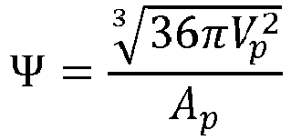
- Typische Sphärizitätswerte Ψ für verschiedene Partikeltypen sind:
Kugel: 1,0 Tropfen, Blase, rundes Korn: 0,7 - 1,0 Eckiges Korn: 0,45 - 0,6 Nadelförmiges Partikel: 0,2 - 0,45 Plättchenförmiges Partikel: 0,06 - 0,16 Partikel mit stark zerklüfteter Oberfläche: 10-8 - 10-4 - Hohe Sphärizitäten Ψ im Sinne der hier vorliegenden Erfindung werden erreicht, wenn Ψ einen Wert von wenigstens 0,7 aufweist.
- Die Partikel eines Pulvers werden generell unabhängig von ihrer Sphärizität Ψ mit Hilfe eines zu messenden volumenäquivalenten Kugeldurchmessers unterschieden und entsprechend ihrer Größe in ausgewählte Klassen eingeordnet. Zur Darstellung einer Partikelgrößenverteilung werden die Mengenanteile bestimmt, mit denen die jeweiligen Partikelklassen im Pulver vorhanden sind.
- Dabei werden unterschiedliche Mengenarten verwendet. Werden die Partikel gezählt, so ist die Mengenart die Anzahl. Bei Wägungen hingegen ist es die Masse bzw. bei homogener Dichte ρ das Volumen. Weitere leiten sich aus Längen, Projektions- und Oberflächen her.
- Man unterscheidet:
Mengenart: Index r Anzahl 0 Länge 1 Fläche 2 Volumen (Masse) 3 - Ein gängiges Mengenmaß zur Beschreibung der Partikelgrößenverteilung in Pulvern bildet die Summenverteilung Qr. Der Index r bezeichnet die Mengenart gemäß obiger Tabelle.
- Die Summenverteilungsfunktion Qr(d) gibt die normierte Menge aller Partikel mit einem Äquivalentdurchmesser kleiner gleich d an. Im Folgenden werden Summenverteilungen der beiden gebräuchlichsten Mengenarten explizit definiert:
• Partikelzahl (r = 0)
Sei Ni die Zahl aller untersuchten Partikel mit einem Durchmesser d kleiner oder gleich dem betrachteten Durchmesser di sowie N die Gesamtzahl aller untersuchten Partikel. Dann ist
• Partikelmasse (r = 3)
Sei mi die Masse aller untersuchten Partikel mit einem Durchmesser d kleiner oder gleich dem betrachteten Durchmesser di sowie m die Gesamtmasse aller untersuchten Partikel. Dann ist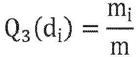
d10: Q3(d10) = 1 0%, d. h. 10 Gew.-% der Partikeln weisen einen Durchmesser kleiner als oder gleich d10 auf. d50: Q3(d50) = 50%, d. h. 50 Gew.-% der Partikeln weisen einen Durchmesser kleiner als oder gleich dso auf. d90: Q3(d90) = 90%, d. h. 90 Gew.-% der Partikeln weisen einen Durchmesser kleiner als oder gleich d90 auf. d99: Q3(d99) = 99%, d. h. 99 Gew.-% der Partikeln weisen einen Durchmesser kleiner als oder gleich d99 auf. d100: Q3(d100) = 100%, d. h. 100 Gew.-% der Partikeln weisen einen Durchmesser kleiner als oder gleich d100 auf. - Überraschenderweise hat sich gezeigt, dass mit Partikeln, die eine Sphärizität Ψ von wenigstens 0,7 aufweisen, ein wesentlicher höherer Partikelfüllgrad erzielt werden kann. So sind erfindungsgemäße Verbundmaterialien zugänglich, die wenigstens 30 Vol.-% der Partikel enthalten, wenn deren Größe einen Wert von d50 ≤ 1,0 µm aufweist, oder wenigstens 40 Vol-% der Partikel, wenn deren Größe einen Wert von d50 > 1,0 µm annimmt.
- In eine besonders bevorzugten Ausführungsform der Erfindung weisen die Partikel eine Sphärizität Ψ von wenigstens 0,8 und besonders bevorzugt von wenigstens 0,9 auf.
- In einer weiteren Ausführungsform enthält das Verbundmaterial bevorzugt wenigstens 35 Vol.-% der Partikel und besonders bevorzugt wenigstens 40 Vol.-% der Partikel, wenn die Größe der Partikeln einen Wert von d50 ≤ 1,0 µm aufweist, bzw. bevorzugt wenigstens 45 Vol-% der Partikel und besonders bevorzugt wenigstens 50 Vol-% der Partikel, wenn die Größe der Partikeln einen Wert von d50 > 1 µm annimmt.
- Vorzugsweise ist das erste Material ausgewählt aus der Gruppe der Polymere, insbesondere der Epoxid- oder Acrylatharze, oder aus der Gruppe der Gläser, insbesondere der Glasfritten oder Glaslote oder aus Kombinationen aus diesen Gruppen.
- Partikel mit einem negativen thermischen Ausdehnungskoeffizienten können aus der Gruppe der folgenden Verbindungen oder aus Kombinationen aus diesen Gruppen:
- ZrW2O8,
- Y2Mo3O12,
- LiAlSiO4,
- LiAlSi2O6,
- Phasensystem ZrO2-WO3-Al2O3-P2O5
- Die Partikel weisen bevorzugt einen negativen thermischen Ausdehnungskoeffizienten α im Bereich von -1,0 × 10⁻⁶/K bis -100 × 10-6/K im Temperaturbereich von -50 °C bis 200 °C auf.
- Bevorzugt sind die Partikel mittels wenigstens einem der folgenden Verfahren hergestellt:
- Sprühkalzinierung (im Besonderen unter Verwendung der Pulsationsreaktortechnologie)
- Filamentierung aus einer Salzschmelze,
- Vertropfung,
- Glaskugelherstellung.
- Im Hinblick auf den Stand der Technik sind daher pulverförmige, negativ dehnende Partikeln wünschenswert, die eine hohe Sphärizität Ψ aufweisen. Beispielhaft sollen an dieser Stelle folgende Verfahren angeführt werden:
Glaskugelherstellung: Der Weg, Partikeln aus einem negativ dehnendem Material herzustellen, nutzt den Umstand, dass solche Materialien u. a. auch über die Glaskeramikroute darstellbar sind: Hierzu wird in einem gängigen Schmelzverfahren zunächst ein im Idealfall kristallfreies Grünglas geschmolzen, das im Zuge eines nachgeschalteten Temperschritts keramisiert und dabei in die eigentliche Glaskeramik überführt wird. Das im ersten Prozessschritt hergestellte Glasschmelze kann beim Abkühlen prinzipiell den üblichen für die Herstellung von Glaskugeln angewandten Heißformgebungsprozessen unterworfen werden. Hierfür sind folgende Verfahrensansätze denkbar: In dem inUS 3,499,745 offenbarten Verfahren, wird ein geschmolzener Glasstrahl auf ein Schlagrad aufprallen lassen, welches bei Realisierung hinreichend großer Kräfte den Glasstrahl dazu bringt, in Teilstränge, sog. Filamente, aufzubrechen. Diese werden anschließend zunächst durch einen beheizten Bereich, eine Kühlregion und schließlich in eine Sammelzone geschleudert. Infolge der nach der Filamentbildung wirksam werdenden Tendenz zur Minimierung der Oberflächenspannung verrunden diese. Gemäß derEP 1 135 343 B1 wird dabei eine hinreichende Sphärizität erzielt, wenn eine Relaxationszeit ab dem Zeitpunkt der Filamentbildung verstrichen ist, die durch die Gleichung T = (d × µ) /beschrieben werden kann. Dabei handelt es sich bei d um den Durchmesser der gebildeten Kugeln, µ die Viskosität des Filaments und die Oberflächenspannung des Filaments während der Relaxationszeit. Wie in der
US 3,495,961 beschrieben, kann anstelle des Schlagrads auch ein Rotor verwendet werden. Andere bekannte Verfahren zur Herstellung von Glaskugeln umfassen das Aufblasen eines brennenden Gasstroms quer durch einen geschmolzenen Glasstrahl, um das Glas in einzelne Teilchen zu zerteilen. - Derartige Verfahren sind in der
US 3,279,905 offenbart. Alternativ dazu können Glaspartikeln niedrigerer Sphärizität, wie in derDD 282 675 A5 - Filamentierung von Salzschmelzen: Analog zur oben beschriebenen
Filamentbildung und der anschließenden, infolge von Relaxationseffekten zur Verringerung der Oberflächenenergie auftretenden Bildung von sphärischen Tropfen aus einem aufgeschmolzenen Glasstrahl kann diese entsprechend aus einem aus einer Salzschmelze erzeugten Materialstrahl erfolgen. Technologisch kann hierzu in ähnlicher Weise verfahren werden, wobei zu beachten ist, dass sich die Viskosität eines aufgeschmolzenen Glases sich von derjenigen einer Salzschmelze je nach der im jeweiligen Fall gewählten Temperatur deutlich voneinander unterscheiden kann. Das tropfenförmige Material muss durch Durchleiten durch einen noch heißeren Bereich zunächst in eine präkeramische, häufig poröse, aber abgesehen von einem isotropen Schrumpf formstabile Zwischenstufe überführt und anschließend weiter - entweder noch im selben oder in einem gesonderten zusätzlichen, nachgeschalteten Temperschritt - in das eigentliche negativ dehnende Material überführt werden. Idealerweise werden so dicht gesinterte Kugeln aus dem negativ dehnenden Material erhalten. - Sprühkalzinierunq (unter Verwendung der Pulsationsreaktortechnologie): Bei Verwendung eines Pulsationsreaktors, wie in der
DE 10111938 A1 ,DE 102006027133 A1 ,DE 102006039462 A1 oderEP 1927394 A1 offenbart, wird eine gasförmige oder eine flüssige Mischung in Form einer Lösung, Suspension oder Dispersion, die alle Komponenten zur Herstellung des negativ dehnenden Materials enthält, in einen pulsierenden Heißgasstrom eingebracht - in letzterem Fall durch feines Zerstäuben. Dabei wird der pulsierende Heißgasstrom selbst innerhalb eines Heißgaserzeugers am Reaktor durch die Verbrennung von Erdgas oder Wasserstoff mit Umgebungsluft erzeugt. Je nach Wahl der Lage des Einsprühpunktes herrschen dort Temperaturen zwischen 500 und 1500 °C. Im pulsierenden Heißgasstrom wird ein Zwischenprodukt gebildet, das durch weitere thermische Nachbehandlung im gleichen oder in einem anderen Reaktor in die endgültige Form überführt. In ersterem Fall kann der Reaktor mit einer zusätzlichen Brennstoffzufuhr versehen werden, die entlang des pulsierenden Heißgasstroms dem Einsprühpunkt nachgelagert ist. - Vertropfungsverfahren: Beim Vertropfungsverfahren wird von einer wässrigen oder lösemittelbasierten Salzlösung oder einem Sol als Vorstufe für das negativ dehnende Material bzw. einer nanopartikulären Lösung des negativ dehnenden Materials ausgegangen und über eine geeignete Düsenvorrichtung in Tropfen überführt. Die Tropfen werden nach ihrer Bildung wahlweise direkt in einem geeigneten Prozessgasstrom getrocknet, wie in der
US 4043507 oderUS 5500162 beschrieben, oder durch Einbringen in ein geeignetes flüssiges Medium, wie in derUS 5484559 ,US 6197073 ,US 2004/0007789 A1 oderWO 2015/014930 A1 offenbart, zunächst zu weiterer Flokkulation angeregt und anschließend gealtert, gewaschen und getrocknet. Die auf diese Weise dargestellten sphärischen, porösen Grünkörper werden in einem anschließenden Sinterschritt zu einem negativ dehnenden Keramikkörper mit hoher Sphärizität verdichtet. - Es werden Formulierungen zur Herstellung von Verbundmaterialien (polymerbasierten Komposite bzw. Kompositvorstufe), z. B. für die Verwendung als Klebematerialien, angegeben, in denen bei gleichen Volumenfüllgraden die Viskosität der partikelgefüllten Formulierung im Fall der Verwendung von nicht-sphärischen Partikeln signifikant höher ist als bei der Verwendung der erfindungsgemäß hergestellten, Partikeln hoher Sphärizität, vorausgesetzt Partikelgröße bzw. Partikelgrößenverteilung sind in beiden Fällen gleich.
- Weiterhin werden Formulierungen zur Herstellung von Verbundmaterialien (polymerbasierte Komposite oder Kompositvorstufen), z. B. für die Verwendung als Klebematerialien, bereitgestellt, in denen sich die entsprechenden Formulierungen ohne wesentliche Änderung der Viskosität im Fall der sphärischen Variante mit deutlich höheren Füllgraden versehen lassen als im Fall der nicht-sphärischen Ausführungsform. Vorausgesetzt ist auch in diesem Fall wieder, dass sich Partikelgröße und Partikelgrößenverteilung in beiden Fällen nicht wesentlich unterscheiden.
- Gelöst wird die Aufgabe auch durch ein Klebematerial umfassend das erfindungsgemäße Verbundmaterial, insbesondere zum Verkleben von Verpackungen für Halbleiter.
- Allen bisher im Stand der Technik zur Herstellung der negativ dehnenden Materialien beschriebenen Verfahren ist gemein, dass das im jeweiligen Prozess erzeugte Rohmaterial entweder monolithisch oder doch zumindest in undefiniert grobkörniger Struktur anfällt und durch weitere Zerkleinerungsschritte, in der Regel Feinmahlprozesse, in eine endgültige Darreichungsform als Pulver mit definierter Partikelgröße und Partikelgrößenverteilung gebracht werden muss. Häufig liegt die zu erreichende Partikelgröße im µm- oder sub-µm-Bereich. Erst hierdurch wird eine weitere Prozessierung möglich. Hierbei ist im Besonderen die Einarbeitung in organische Massen, beispielsweise Polymere oder deren Harzvorstufen zu nennen, welche als Klebstoff eingesetzt werden können. Organische Verbindungen, insbesondere Polymere, weisen in der Regel eine sehr hohe Wärmedehnung auf. Sollen solche Polymere zur Verklebung eingesetzt werden, beispielsweise zur Verklebung von anorganischen Materialien, beispielsweise im optischen Bereich oder in der Chip-Industrie, kann es hierbei zu Schwierigkeiten, wenn der Klebeverbund größeren thermischen Schwankungen ausgesetzt ist. Aufgrund der sehr stark unterschiedlichen Ausdehnungskoeffizienten des Polymers und der zu verklebenden, anorganisch ausgebildeten Materialien werden zwischen den zu verbindenden Materialien thermomechanische Spannungen induziert, welche im schlimmsten Falle sogar zu einem mechanischen Versagen des geklebten Bauteils führen können. Solche Versagensfälle können vermieden oder zumindest deutlich reduziert werden, wenn der integrale thermische Ausdehnungskoeffizient, also der für das gesamte Klebematerial resultierende Ausdehnungskoeffizient, reduziert wird. Dies wird auf einfache Weise durch den Zusatz von anorganischen Füllstoffen mit niedriger thermischer Dehnung bewirkt. Bekannte Füllstoffe, welche heute zu diesem Zweck eingesetzt werden, umfassen SiO2, sowohl in kristalliner Form als auch amorph als sogenannte Kieselsäure bzw. als Quarzglaspartikel. Die SiO2-basierten Materialien weisen dabei einen betragsmäßig zwar sehr geringen, jedoch positiven thermischen Ausdehnungskoeffizienten auf, dessen Wert in der Größenordnung von etwa +1 × 10⁻⁶/K liegt.
- Über Zerkleinerungsprozesse, wie z. B. besagte Feinmahlprozesse, wie sie wie eben erwähnt zur Darstellung der negativ dehnenden Pulvermaterialien mit einer Partikelgröße im mikro- oder sub-mikroskaligen Bereich notwendig sind, ist die Darstellung sphärischer Pulverpartikeln praktisch nicht möglich. Vielmehr werden hierbei scherbenförmige, mit Ecken und Kanten versehene Partikeln gebildet. Diese weisen demnach eine Sphärizität von deutlich kleiner als 0,7 auf.
- Nicht-sphärische Partikeln ein und desselben Materials lassen sich in vielen Anwendungen deutlich schlechter verarbeiten als ihre sphärischen Pendants - gleiche Partikelgröße und Partikelgrößenverteilung vorausgesetzt. Insbesondere bei der Einarbeitung in thermoplastische und flüssige Matrizes (wie bei flüssigen Harzvorstufen für duroplastische Kleber der Fall) macht sich dieser Umstand bemerkbar: Bei gleichen Volumenfüllgraden ist die Viskosität der partikelgefüllten Formulierung im Fall der Verwendung von nicht-sphärischen Partikeln signifikant höher als bei der Verwendung von sphärischen Partikeln aus dem gleichen Material, wenn diese eine vergleichbare Partikelgröße bzw. Partikelgrößenverteilung besitzen. Umgekehrt lassen sich entsprechende Formulierungen im Fall der sphärischen Variante mit deutlich höheren Füllgraden versehen als im Fall der nicht-sphärischen Ausführungsform. Dies ist auf den Umstand zurückzuführen, dass die innere Reibung in mit nicht-sphärischen Partikeln gefüllten Formulierungen dadurch erhöht ist, dass die Partikeln zum gegenseitigen Verhaken neigen, wenn sie sich infolge der Einwirkung von äußeren Scherkräften innerhalb der Formulierung aneinander vorbei bewegen. Im Fall sphärischer Partikeln vermögen diese hingegen besser aneinander vorbei zu gleiten.
- Der Umstand, dass sich bei Verwendung von sphärischen Partikeln in hiermit gefüllten Formulierungen unter vergleichbaren Bedingungen deutlich höhere Volumenfüllgrade erzielen lassen, ist in der Praxis von großer Relevanz: So lassen sich beispielsweise einerseits für Klebematerialien, die als Vergussmassen (Molds, Encapsulants) dienen sollen, final nach dem Aushärten Komposite mit minimierten thermischen Ausdehnungskoeffizienten realisieren, ohne dass die Verarbeitbarkeit der flüssigen Klebstoffvorstufen vor dem Aushärten durch das Einbringen des Füllstoffs verloren geht. Andererseits sind Füllstoffe in Klebematerialien, die zum Unterfüllen beim Fügen von Halbleiterbauteilen zur Anwendung kommen (Underfills), in ihrer maximalen Partikelgröße beschränkt. Die Grenze kann infolge des fortschreitenden Trends zur Minimalisierung hier deutlich im submikroskaligen Bereich liegen. Aufgrund der mit kleiner werdender Partikelgröße immer stärker wirksam werdender Partikel-Partikel-Wechselwirkungen steigt die Viskosität der Vorstufen von entsprechenden Kompositen schon bei geringeren Füllgraden häufig stark an. Schnell ist hier eine Grenze erreicht, bei der die Verarbeitbarkeit der Vorstufe nicht mehr gewährleistet ist. Durch den Einsatz von sphärischen Füllstoffpartikeln lässt sich der maximal erreichbare Füllgrad gegenüber demjenigen Wert, wie er im Fall der Verwendung von nicht-sphärischen Partikeln erzielbar ist, nochmals deutlich steigern. In diesen Fällen ist die Verarbeitbarkeit der Klebervorstufe auch bei höheren Füllgraden immer noch gegeben. Gleichzeitig ist der thermische Ausdehnungskoeffizient des Klebematerials nach Aushärten wunschgemäß signifikant reduziert.
- Die Partikel mit negativer thermischer Ausdehnung sind für die Klebstoffindustrie von großer Bedeutung: durch die Zugabe als Füllstoffes zu einem Polymer/ Mehrkomponentenklebstoff kann dessen eigene thermische Ausdehnung stark minimiert und somit eine Diskrepanz zwischen dem unterschiedlichen Dehnungsverhalten der zu verbindenden Materialien reduziert werden. Mechanische Spannungen zwischen den zu verbindenden Komponenten werden dadurch erheblich reduziert und die Lebensdauer des gesamten Bauteils signifikant verlängert bzw. überhaupt erst in einem für die Anwendung erheblichem Maße ermöglicht, insbesondere bei der Verklebung in der Chip-Technologie (Molding, Potting, Underfill), aber auch bei anderen klebetechnischen Fragestellungen (z.B. Automobil, Linsenaufbau bei Kameras).
- Ein Ausgangsglas für eine final negativ dehnende Glaskeramik der Zusammensetzung 24,2 Gew.-% ZrO2, 68,6 Gew.-% WO3, 1,4 Gew.-% Al2O3 und 5,8 Gew.-% P2O5 wurde in einem Ablauftiegel bei einer Temperatur von 1650 °C erschmolzen.
- Die Glasschmelze wurde im gewählten Schmelzaggregat auf einer Temperatur von 1550 °C gehalten. Über eine am Boden des Tiegels angebrachte Düse von einem Durchmesser von 1 mm wurde es ablaufen lassen. Der so erzeugte Glasstrahl wurde auf ein 53-zähniges, 8 mm dickes Schlagrad mit einem Außendurchmesser von 135 mm tropfen lassen, das sich mit einer Frequenz von 5000 U/min um die eigene Achse drehte. Auf diese Weise wurde der Glasstrom in einzelne Stücke filamentiert und mit einem Neigungswinkel zwischen 20 bis 30° gemessen gegen die Horizontale beschleunigt. Anschließend wurde er durch einen 3 m langen, mit zwei Gasbrennern auf 1550 °C beheizten, kurvenförmig gebauten Rohr-ofen geleitet, der die Flugbahn des filamentierten Glasstroms nachzeichnete. Infolge der Neigung zur Minimierung der Oberflächenenergie formten sich die länglich geformten Filamente zu Kugeln um. Nach Austritt aus dem Rohr-Ofen wurden die Glaskugeln durch weiteren Flug an Luft bis zum Erreichen einer ausreichenden Formstabilität abkühlen lassen und schließlich in einem Sammelbehälter aufgefangen.
- Die nach dem beschriebenen Heißformgebungsprozess hergestellten, abgekühlten, weitestgehend röntgenamorphen Grünglaskugeln wurden im Zuge einer weiteren Temperaturbehandlung bei einer Maximaltemperatur von 650 °C und Haltezeit von 12 bis 24 Stunden keramisiert und somit in die finale, negativ dehnende Glaskeramik überführt.
- Ein Ausgangsglas für eine final negativ dehnende Glaskeramik der Zusammensetzung 24,2 Gew.-% ZrO2, 68,6 Gew.-% WO3, 1,4 Gew.-% Al2O3 und 5,8 Gew.-% P2O5 wurde in einem Ablauftiegel bei einer Temperatur von 1650 °C erschmolzen.
- Die Glasschmelze wurde im gewählten Schmelzaggregat auf einer Temperatur von 1550 °C gehalten. Über eine am Boden des Tiegels angebrachte Düse von einem Durchmesser von 1 mm wurde es ablaufen in einen Spalt zwischen zwei sich gegeneinander drehenden, wassergekühlten Walzen laufen lassen und dabei unter Bildung eines Grünglasbandes abgeschreckt. Das Grünglasband wurde mechanisch mit einem Hammer in kleine Splitter vereinzelt.
- Die Glassplitter wurden durch Vormahlung in einer Kugelmühle grobzerkleinert und hiervon die Pulverfraktion mit einer Partikelgröße d100 < 100 µm abgesiebt. Dieses abgesiebte Grünglaspulver wurde in einem weiteren nachgeschalteten Schritt in einer Trockenmahlung auf einer Gegenstrahlmühle auf eine Partikelgröße mit einer Verteilung von d10 = 0,8 µm, d50 = 5,2 µm, d90 = 12,4 µm und d99 = 18,8 µm weiter zerkleinert.
- Durch Einbringen des Pulvers in eine Erdgasflamme werden die Glaspartikeln wieder aufgeschmolzen und erfahren dabei infolge der Tendenz zur Minimierung der Oberflächenenergie eine Verrundung. Nach Austritt aus der Flamme werden die Partikeln abkühlen lassen und in einem Sammelbehälter aufgefangen.
- Die nach dem beschriebenen Heißformgebungsprozess hergestellten, abgekühlten, weitestgehend röntgenamorphen Grünglaskugeln wurden im Zuge einer weiteren Temperaturbehandlung bei einer Maximaltemperatur von 650 °C und Haltezeit von 12 bis 24 Stunden keramisiert und somit in die finale, negativ dehnende Glaskeramik überführt.
- 964 g Yttriumacetat-tetrahydrat und 754 g Ammoniummolybat-tetrahydrat wurden in eine Kugelmühle gegeben und dort zur Herstellung einer möglichst homogenen Pulvermischung für 4 h gemahlen. Als Mahlkugeln wurden hierzu Al2O3-Kugeln mit einem Durchmesser von 40 mm verwendet.
- Nach dem Absieben wurde die Pulvermischung in einen Platinablauftiegel gegeben und dort vorsichtig auf eine Temperatur von 100 °C gebracht, knapp oberhalb des Schmelzpunkts von Ammoniummolybdat-tetrahydrat, der bei 90 °C liegt. Dabei bildet sich eine Salzschmelze aus, die über eine am Boden des Tiegels angebrachte Düse von einem Durchmesser von 2 mm wurde ablaufen lassen wurde. Der so erzeugte aus der Salzschmelze bestehende Strahl wurde auf ein 53-zähniges, 8 mm dickes Schlagrad mit einem Außendurchmesser von 135 mm tropfen lassen, das sich mit einer Frequenz von 5000 U/min um die eigene Achse drehte. Auf diese Weise wurde der aus der Salzschmelze bestehende Strahl in einzelne Stücke filamentiert und mit einem Neigungswinkel zwischen 20 bis 30° gemessen gegen die Horizontale beschleunigt. Anschließend wurde er durch einen 3 m langen, kurvenförmig gebauten Rohrofen geleitet, der die Flugbahn des filamentierten aus der Salzschmelze bestehenden Strahls nachzeichnete. Der Ofen wurde dergestalt elektrisch beheizt, dass er in der Eintrittszone auf moderaten Temperaturen von 100 -
- 120 °C gehalten wurde, so dass die Salzschmelze weiter erhalten blieb und sich die zunächst noch länglich geformten Filamente infolge der Neigung zur Minimierung der Oberflächenenergie zu noch flüssigen Kugeln umformten. In den nachgeschalteten Zonen wurde die Temperatur dann deutlich höher gewählt - Temperaturen von rund 900 °C wurden hier erreicht. Infolgedessen trat hier ein erster Schritt zur Calcinierung der flüssigen Kugeln ein, wobei sich poröse, präkeramische Partikeln als Zwischenstufe ausbildeten. Nach Austritt aus dem Rohrofen wurden diese durch weiteren Flug an Luft abkühlen lassen und schließlich in einem Sammelbehälter aufgefangen.
- Die porösen, präkeramischen Partikeln wurden einem weiteren Calcinierungsschritt in einem Ofen bei 900 °C und einer Haltezeit von 7 - 8 h zu den finalen, aus negativ dehnenden Y2Mo3O12-Material bestehenden Kugeln verdichtet.
- 584,5 g (2,0 mol) Ethylendiamintetraessigsäure (EDTA) wurden in 6,0 L (333 mol) Wasser suspendiert. Parallel dazu wurden 560 g (4,0 mol) 25%ige wässrige Ammoniumhydroxidlösung in 3,6 L (200 mol) Wasser gegeben. Die Ammoniumhydroxidlösung wurde anschließend unter Rühren zur EDTA-Lösung zugetropft. Anschließend wurden zu dieser teilneutralisierten EDTA-Lösung 644,5 g (2,0 mol) Zirkoniumoxidichlorid-octahydrat ZrOCl2 × 8 H2O zugegeben. Infolgedessen fiel ein dicker, weißer Niederschlag aus, der sich bei Erhitzen der Lösung auf 100 °C wieder auflöste. Die Lösung wurde bei dieser Temperatur für 1 h rühren und anschließend über Nacht abkühlen lassen. In der Folge entstand durch teilweises Ausfällen der farblosen Kristalle eines Zr-EDTA-Komplexes eine trübe Lösung, die am Rotationsverdampfer bis zur Trockene eingeengt wurde. Anschließend wurde der feste Rückstand des Gemischs aus Zr-EDTA-Komplex und NH4Cl (Gewichtsverhältnis: 78% : 22%) für 24 h bei 110 °C getrocknet.
- 292,2 g (1,0 mol) Ethylendiamintetraessigsäure wurden in 5,0 L (278 mol) Wasser gelöst und anschließend mit 300 ml (2,0 mol) 25%iger wässriger Ammoniumhydroxidlösung versetzt. Darin wurden 463,7 g (1,7 mol WO3-Äquivalent) Ammoniummetawolframat-hydrat (NH4)6H2W12O40 × n H2O (85 Gew.-% WO3) gelöst. Anschließend wurden 487,1 g des Zr-EDTA-Komplex/NH4Cl-Gemischs (i. e. 1,0 mol Zr-EDTA-Komplex) zugegeben und unter mildem Erwärmen darin gelöst.
- Die Lösung wird mit Hilfe einer Schlauchpumpe in einen Pulsationsreaktor mit einem Volumenstrom von 3 kg/h gefördert und dort über eine 1,8 mm Titandüse in das Reaktorinnere fein zerstäubt und dort thermisch behandelt. Die Temperatur der Brennkammer wird dabei auf 1300 °C, diejenige des Resonanzrohrs auf 1200 °C gehalten. Das Verhältnis der Verbrennungsluftmenge zur Brennstoffmenge (Erdgas) betrug 10 : 1 (Luft: Gas).
- Das Pulver wird in einen quaderförmigen Korundtiegel gefüllt und in einen Kammerofen gestellt. Das Glühgut wird im Ofen in Luftatmosphäre zur vollständigen Verdichtung der aus ZrW2O8 bestehenden, sphärischen mikroskaligen Partikeln auf eine Temperatur von 1200 °C gebracht und nach der Temperatur durch Einbringen in einen kalten Luftstrom schlagartig gequencht, so dass das bei Raumtemperatur metastabile Mischoxid keine Gelegenheit bekam, wieder in die Einzelkomponenten zu zerfallen.
- 58,5 g (0,2 mol) Zirkoniumoxichlorid-octahydrat ZrOCl2 × 8 H2O wurden zu 500 mL (27,8 mol) Wasser gegeben und darin gelöst. Zur Mischung wurden zusätzlich 252,2 g (1,2 mol) Citronensäure-Monohydrat gegeben und gelöst. Die Verbindung fungierte als Komplexbildner zur Stabilisierung der Zr4+-Ionen, um deren frühzeitiges Ausfällen im Zuge der weiteren Prozessierung zu verhindern. Parallel wurde eine separate Lösung von 90 g (0,33 mol WO3-Äquivalent) Ammoniummetawolframat (NH4)6H2W12O40 · × H2O (85% WO3) in 500 mL Wasser angesetzt. Anschließend wurden beide Lösungen vereinigt.
- Aus der so hergestellten Stammlösung wurden mittels eines Vertropfungsverfahrens über Düsen und/oder Kanülen formstabil Gelkörper der Größen 0,3 bis 2,5 mm durch Eintauchen sowie Reaktion in einer Ammoniaklösung bei einer Temperatur von 60 °C erhalten.
- Diese Gelkörper wurden im Anschluss durch Calcinierung bei zu gesinterten Kugeln durch ein Sinterverfahren geformt. Die Sinterung erfolgte an Luftatmosphäre unter Normaldruck. Zunächst wurde in einem ersten Schritt auf 700 - 800 °C erhitzt und dort für 12 h gehalten, um die organischen Bestandteile aus dem Gel rückstandsfrei auszubrennen. Anschließend wurde die Temperatur auf 1180 °C erhöht und dort für weitere 2 h zur Realisierung der eigentlichen Reaktivsinterung gehalten. Um einen Zerfall des bei Raumtemperatur metastabilen ZrW2O8 in die Einzeloxide zu vermeiden, wurden die gebildeten keramischen ZrW2O8-Sphären zum Abkühlen in einen kalten Luftstrom gegeben.
- Zu 10,0 g eines Bisphenol-A-diglycidylether-basierten Epoxidharzes (Dichte: 1,16 g/cm3) mit einer Nullscherratenviskosität von 0,6 Pa s wurden 69,4 g Glaskeramikpulver mit ZrW2O8 als Hauptkristallphase einer Glaskeramik aus dem Phasensystem ZrO2-WO3-Al2O3-P2O5 (thermischer Ausdehnungskoeffizient im Temperaturbereich zwischen 75 und 125 °C: -2,2 ppm/K; Dichte: 5,37 g/cm3) gegeben, das eine Partikelgrößenverteilung von d10 = 1,27 µm, d50 = 8,56 µm, d90 = 17,33 µm und d99 = 26,14 µm aufwies. Dessen Partikeln besaßen eine Sphärizität von im Mittel Ψ= 0,93. Zur hinreichenden Dispergierung des Füllstoffpulvers wurde die Mischung für 1 h auf einem Taumler homogenisiert. Die resultierende Klebervorstufe wies einen Volumenfüllgrad von 60 Vol.-% und scherverdünnendes Fließverhalten auf, wobei die Nullscherratenviskosität 114 Pa s betrug. Sie war somit im Blick auf die adressierte Anwendung als Mold/Encapsulant-Klebematerial in Verpackungsanwendungen im Halbleiterbereich (IC-Packaging) noch verarbeitbar.
- Es wurde versucht, nach derselben Prozedur eine Klebervorstufe mit einem aus nicht-sphärischen Partikeln (Ψ= 0,58) bestehenden Glaskeramikpulvers mit ZrW2O8 als Hauptkristallphase einer Glaskeramik aus dem Phasensystem ZrO2-WO3-Al2O3-P2O5herzustellen, das eine Partikelgrößenverteilung mit folgenden Werten aufwies: d10 = 1,08 µm, d50 = 7,78 µm, d90 = 15,26 µm d99 = 21,06 µm. In diesen Fällen wurde allerdings nur noch eine knetartige Masse erhalten, die mit in Blick auf die Zielanwendung üblicherweise eingesetzten Dosierapparaturen und -verfahren nicht mehr gehandhabt werden konnte.
- Zu 20,0 g eines Bisphenol-A-diglycidylether-basierten Epoxidharzes (Dichte: 1,16 g/cm3) mit einer Nullscherratenviskosität von 0,6 Pa s wurden 43,5 g Glaskeramikpulver mit ZrW2O8 als Hauptkristallphase einer Glaskeramik aus dem Phasensystem ZrO2-WO3-Al2O3-P2O5 (thermischer Ausdehnungskoeffizient im Temperaturbereich zwischen 75 und 125 °C: -2,2 ppm/K; Dichte: 5,37 g/cm3) gegeben, das eine Partikelgrößenverteilung von d10 = 0,18 µm, d50 = 0,56 µm, d90 = 1,17 µm und d99 = 1,82 µm aufwies. Dessen Partikeln besaßen eine Sphärizität von Ψ= 0,91. Zur hinreichenden Dispergierung des Füllstoffpulvers wurde die Mischung für 1 h auf einem Taumler homogenisiert. Die resultierende Klebervorstufe wies einen Volumenfüllgrad von 32 Vol.-% und ein Newtonsches Fließverhalten auf, wobei die Viskosität 13 Pa s betrug. Sie war somit im Blick auf die adressierte Anwendung als Underfill-Klebematerial in Verpackungsanwendungen im Halbleiterbereich (IC-Packaging) noch verarbeitbar.
- Es wurde versucht, nach derselben Prozedur eine Klebervorstufe mit einem aus nicht-sphärischen Partikeln (Ψ= 0,58) bestehenden Glaskeramikpulvers mit ZrW2O8 als Hauptkristallphase einer Glaskeramik aus dem Phasensystem ZrO2-WO3-Al2O3-P2O5herzustellen, das eine Partikelgrößenverteilung mit folgenden Werten aufwies:
d10 = 0,09 µm, d50 = 0,36 µm, d90 = 0,91 µm d99 = 1,55 µm. In diesen Fällen wurde eine Klebervorstufe mit einer Nullscherratenviskosität von 85 Pa s erhalten, die mit in Blick auf die Zielanwendung üblicherweise eingesetzten Dosierapparaturen und -verfahren nur noch sehr schwer zu handhaben war.
wobei die Partikel im erfindungsgemäßen Verbundmaterial ZrW2O8 als Hauptkristallphase aus dem Phasensystem ZrO2-WO3-Al2O3-P2O5 umfassen.
Claims (4)
- Verbundmaterial, umfassend wenigstens ein erstes Material und Partikel, wobei die Partikel einen negativen thermischen Ausdehnungskoeffizienten α aufweisen, wobei die Partikel eine Sphärizität Ψ von wenigstens 0,7 aufweisen und das Verbundmaterial wenigstens 30 Vol.-% der Partikel bei einer Partikelgröße von d50 ≤ 1,0 µm enthält, oderdass das Verbundmaterial wenigstens 40 Vol.-% der Partikel bei einer Partikelgröße d50 > 1,0 µm enthält,dadurch gekennzeichnet, dassdie Partikel- ZrW2O8 als Hauptkristallphaseaus dem Phasensystem ZrO2-WO3-Al2O3-P2O5 umfassen.
- Verbundmaterial nach Anspruch 1,
dadurch gekennzeichnet, dass
das erste Material ausgewählt ist aus der Gruppe der Polymere, insbesondere der Epoxidharze, oder aus der Gruppe der Gläser, insbesondere der Glasfritten oder Glaslote oder aus Kombinationen aus diesen Gruppen. - Verbundmaterial nach einem der vorhergehenden Ansprüche,
dadurch gekennzeichnet, dass
die Partikel einen negativen thermischen Ausdehnungskoeffizienten α im Bereich von -1,0 × 10⁻⁶/K bis -100 × 10-6/K im Temperaturbereich von -50 °C bis 200 °C aufweisen. - Klebematerial umfassend das Verbundmaterial nach einem der vorhergehende Ansprüche, insbesondere zum Verkleben von Verpackungen für Halbleiter.
Applications Claiming Priority (1)
| Application Number | Priority Date | Filing Date | Title |
|---|---|---|---|
| DE102017128734.5A DE102017128734A1 (de) | 2017-12-04 | 2017-12-04 | Verbundmaterial, umfassend wenigstens ein erstes Material und Partikel, wobei die Partikel einen negativen thermischen Ausdehnungskoeffizienten α aufweisen, und Klebematerial umfassend das Verbundmaterial |
Publications (2)
| Publication Number | Publication Date |
|---|---|
| EP3492437A1 EP3492437A1 (de) | 2019-06-05 |
| EP3492437B1 true EP3492437B1 (de) | 2022-10-19 |
Family
ID=64559527
Family Applications (1)
| Application Number | Title | Priority Date | Filing Date |
|---|---|---|---|
| EP18209131.4A Not-in-force EP3492437B1 (de) | 2017-12-04 | 2018-11-29 | Verbundmaterial, umfassend wenigstens ein erstes material und partikel, wobei die partikel einen negativen thermischen ausdehnungskoeffizienten alpha aufweisen, und klebematerial umfassend das verbundmaterial |
Country Status (7)
| Country | Link |
|---|---|
| US (1) | US10759975B2 (de) |
| EP (1) | EP3492437B1 (de) |
| JP (1) | JP7254493B2 (de) |
| KR (1) | KR20190065974A (de) |
| CN (1) | CN109867448B (de) |
| DE (1) | DE102017128734A1 (de) |
| TW (1) | TW201927971A (de) |
Families Citing this family (4)
| Publication number | Priority date | Publication date | Assignee | Title |
|---|---|---|---|---|
| CN110845980A (zh) * | 2019-10-09 | 2020-02-28 | 深圳大学 | 一种cob封装胶及其制备方法 |
| DE102020207388A1 (de) * | 2020-06-15 | 2021-12-16 | Schott Ag | Verfahren zur Herstellung eines leitenden Verbundmaterials für eine Batterie sowie leitendes Verbundmaterial |
| CN112299846B (zh) * | 2020-11-16 | 2022-05-24 | 郑州大学 | 一种负热膨胀陶瓷Ta2W2O11及其固相烧结合成方法 |
| CN116003980B (zh) * | 2022-10-27 | 2023-10-13 | 宁波家联科技股份有限公司 | 一种耐热高强尺寸稳定的聚乳酸3d打印材料及其制备方法 |
Family Cites Families (30)
| Publication number | Priority date | Publication date | Assignee | Title |
|---|---|---|---|---|
| BE627719A (de) | 1962-03-27 | |||
| BE661293A (de) | 1964-04-21 | 1900-01-01 | ||
| US3495961A (en) | 1966-12-27 | 1970-02-17 | Potter Brothers Inc | Method and apparatus for vitreous bead manufacture |
| US4043507A (en) | 1971-05-05 | 1977-08-23 | United Kingdom Atomic Energy Authority | Apparatus for the formation of liquid droplets |
| DD282675A5 (de) | 1989-04-24 | 1990-09-19 | Trisola Steinach Veb | Solarisationsstabilisierte hochindex-mikroglaskugeln und verfahren zu ihrer herstellung |
| DE4042594A1 (de) | 1990-11-05 | 1992-07-02 | Nukem Gmbh | Verfahren zur herstellung von aluminiumoxidkugeln |
| DE4214272A1 (de) | 1992-05-04 | 1993-11-11 | Nukem Gmbh | Verfahren und Vorrichtung zur Herstellung von Mikrokugeln |
| US5484559A (en) | 1994-04-14 | 1996-01-16 | Zircoa Inc. | Apparatus and process for manufacturing balls made of a ceramic material |
| US5719225A (en) * | 1994-06-13 | 1998-02-17 | Sumitomo Chemical Company, Ltd. | Filler-containing resin composition suitable for injection molding and transfer molding |
| US6209352B1 (en) | 1997-01-16 | 2001-04-03 | Corning Incorporated | Methods of making negative thermal expansion glass-ceramic and articles made thereby |
| DE19800460A1 (de) * | 1998-01-08 | 1999-04-29 | Siemens Ag | Befestigung eines Halbleiterkörpers auf einer Leiterplatte |
| EP1087915A2 (de) | 1998-05-19 | 2001-04-04 | Corning Incorporated | Materialen mit negativer thermischer ausdehnung,verfahren zur herstellung und verwendung dieser materialen |
| ATE246153T1 (de) | 1998-10-06 | 2003-08-15 | Pq Holding Inc | Verfahren und vorrichtung zur herstellung von glaskugeln |
| US6506699B1 (en) | 1998-10-23 | 2003-01-14 | Kabushiki Kaisha Ohara | Negative thermal expansion glass ceramic and method for producing the same |
| US7192997B2 (en) * | 2001-02-07 | 2007-03-20 | International Business Machines Corporation | Encapsulant composition and electronic package utilizing same |
| DE10111938A1 (de) | 2001-03-13 | 2002-09-26 | Merck Patent Gmbh | Herstellung von Hochtemperatur-Supraleiter-Pulvern in einem Pulsationsreaktor |
| US20030187117A1 (en) * | 2002-03-29 | 2003-10-02 | Starkovich John A. | Materials and method for improving dimensional stability of precision electronic optical photonic and spacecraft components and structures |
| US6797203B2 (en) | 2002-07-12 | 2004-09-28 | Cerco Llc | Method of forming ceramic beads |
| DE102006027133A1 (de) | 2006-06-12 | 2007-12-13 | Merck Patent Gmbh | Verfahren zur Herstellung von Granat-Leuchtstoffen in einem Pulsationsreaktor |
| DE102006039462B4 (de) | 2006-08-23 | 2010-02-18 | Ibu-Tec Advanced Materials Ag | Verfahren zur Herstellung von Partikeln |
| DE102006046803A1 (de) | 2006-09-29 | 2008-04-03 | Ibu-Tec Gmbh & Co. Kg | Verfahren und thermischer Reaktor zur Herstellung von Partikeln |
| JP5549568B2 (ja) * | 2009-12-15 | 2014-07-16 | 信越化学工業株式会社 | 光半導体素子封止用樹脂組成物及び当該組成物で封止した光半導体装置 |
| KR101987280B1 (ko) * | 2012-12-20 | 2019-06-10 | 삼성전기주식회사 | 인쇄회로기판용 수지 조성물, 절연필름, 프리프레그 및 인쇄회로기판 |
| ES2698613T3 (es) | 2013-07-31 | 2019-02-05 | Sigmund Lindner GmbH | Bola sinterizada |
| DE102014220457B4 (de) * | 2014-10-09 | 2020-07-30 | Schott Ag | Verfahren zur Herstellung eines beschichteten Substrats |
| CN104496183A (zh) * | 2014-12-26 | 2015-04-08 | 上海天马有机发光显示技术有限公司 | 一种低温封接玻璃料及复合填料的制备方法 |
| JP6190023B1 (ja) * | 2015-10-07 | 2017-08-30 | 日本化学工業株式会社 | リン酸タングステン酸ジルコニウムの製造方法 |
| WO2017061403A1 (ja) * | 2015-10-07 | 2017-04-13 | 日本化学工業株式会社 | 負熱膨張材及びそれを含む複合材料 |
| CN105482453A (zh) * | 2016-02-03 | 2016-04-13 | 长春长光宇航复合材料有限公司 | 一种低热膨胀系数氰酸酯树脂复合材料及其制备方法 |
| JP6815087B2 (ja) * | 2016-03-28 | 2021-01-20 | 日鉄ケミカル&マテリアル株式会社 | 球状ユークリプタイト粒子およびその製造方法 |
-
2017
- 2017-12-04 DE DE102017128734.5A patent/DE102017128734A1/de not_active Ceased
-
2018
- 2018-11-29 EP EP18209131.4A patent/EP3492437B1/de not_active Not-in-force
- 2018-11-30 CN CN201811458401.6A patent/CN109867448B/zh not_active Expired - Fee Related
- 2018-12-03 TW TW107143245A patent/TW201927971A/zh unknown
- 2018-12-03 JP JP2018226850A patent/JP7254493B2/ja active Active
- 2018-12-04 US US16/208,639 patent/US10759975B2/en not_active Expired - Fee Related
- 2018-12-04 KR KR1020180154395A patent/KR20190065974A/ko not_active Withdrawn
Also Published As
| Publication number | Publication date |
|---|---|
| JP2019112614A (ja) | 2019-07-11 |
| CN109867448B (zh) | 2023-09-29 |
| US10759975B2 (en) | 2020-09-01 |
| KR20190065974A (ko) | 2019-06-12 |
| DE102017128734A1 (de) | 2019-06-06 |
| JP7254493B2 (ja) | 2023-04-10 |
| CN109867448A (zh) | 2019-06-11 |
| TW201927971A (zh) | 2019-07-16 |
| US20190169473A1 (en) | 2019-06-06 |
| EP3492437A1 (de) | 2019-06-05 |
Similar Documents
| Publication | Publication Date | Title |
|---|---|---|
| EP0690031B1 (de) | Zr02-haltige Glaskeramik | |
| AT396925B (de) | Verfahren zur herstellung von glaskörperchen und teilchen einer glasbildnermasse | |
| EP2765977B1 (de) | Lithiumsilikat-glaskeramik und -glas mit einwertigem metalloxid | |
| DE69521185T2 (de) | Hochreines transparentes Quarzglas und Verfahren zu seiner Herstellung | |
| EP3492437A1 (de) | Verbundmaterial, umfassend wenigstens ein erstes material und partikel, wobei die partikel einen negativen thermischen ausdehnungskoeffizienten alpha aufweisen, und klebematerial umfassend das verbundmaterial | |
| EP3499630A1 (de) | Lithiumionenleitendes verbundmaterial, umfassend wenigstens ein polymer und lithiumionenleitende partikel, und verfahren zur herstellung eines lithiumionenleiters aus dem verbundmaterial | |
| EP1074513A2 (de) | Sinterwerkstoffe und deren Herstellungsverfahren und Verwendungen, Dispersionen von Siliciumdioxid-Granulaten und deren Verwendungen, sowie Verwendungen von Siliciumdioxid-Granulaten | |
| EP3904303A1 (de) | Festkörper-lithiumionenleiter | |
| EP2252561B1 (de) | Lichtdurchlässiges hitzeschutzelement mit aluminat- oder borat-modifiziertem siliziumdioxid | |
| EP3122691B1 (de) | Verfahren zur herstellung eines lithiumsilikat-glasrohlings und eines lithiumsilikat-glaskeramikrohlings | |
| EP1449815A2 (de) | Bioaktive Rhenanit-Glaskeramik | |
| EP3428132B1 (de) | Quarzglasbauteil mit hoher thermischer stabilität, halbzeug dafür und verfahren zur herstellung desselben | |
| TW201119970A (en) | Glass-crystalline particles including a glass component and a crystalline component | |
| DE1496488B2 (de) | Verfahren zur herstellung eines glas kirstall mischkoerpers optimaler festigkeit durch gesteuerte entglasung eines glases des systems li tief 2 0 si o tief 2 unter verwendung eines phosphats als keimbildner | |
| DE60130186T2 (de) | Plattenförmiges metalltitanat-komposit und verfahren zu dessen herstellung | |
| EP0974559A2 (de) | Komposit-Lotglas mit niedriger Aufschmelztemperatur, ein Füllstoff hierfür, sowie deren Verwendung | |
| DE2554969C3 (de) | Glasierbare, nichtporöse keramische Sinterkörper hoher mechanischer Festigkeit mit steatitanalogen elektrischen Isolationseigenschaften | |
| EP1611066B1 (de) | Verfahren zur herstellung eines kieselsäuregranulates | |
| WO2013124166A1 (de) | Verfahren zur herstellung von hochreinem sio2 | |
| DE102009033984B4 (de) | Verfahren zur Herstellung von Glas mit definiert inhomogenen optischen Eigenschaften | |
| DE102018221827B4 (de) | Verfahren zur Herstellung einer Glaskeramik und Glaskeramik | |
| DE19546238A1 (de) | Verfahren zur Herstellung von gesinterten Siliciumnitrid | |
| DE102005030518A1 (de) | Verfahren zur Herstellung von Mullit | |
| WO2012113670A1 (de) | VERFAHREN ZUR HERSTELLUNG VON SiO2-FORMKÖRPERN | |
| DE102012202589A1 (de) | Einsatz für einen Schmelztiegel |
Legal Events
| Date | Code | Title | Description |
|---|---|---|---|
| PUAI | Public reference made under article 153(3) epc to a published international application that has entered the european phase |
Free format text: ORIGINAL CODE: 0009012 |
|
| STAA | Information on the status of an ep patent application or granted ep patent |
Free format text: STATUS: THE APPLICATION HAS BEEN PUBLISHED |
|
| AK | Designated contracting states |
Kind code of ref document: A1 Designated state(s): AL AT BE BG CH CY CZ DE DK EE ES FI FR GB GR HR HU IE IS IT LI LT LU LV MC MK MT NL NO PL PT RO RS SE SI SK SM TR |
|
| AX | Request for extension of the european patent |
Extension state: BA ME |
|
| STAA | Information on the status of an ep patent application or granted ep patent |
Free format text: STATUS: REQUEST FOR EXAMINATION WAS MADE |
|
| 17P | Request for examination filed |
Effective date: 20191203 |
|
| RBV | Designated contracting states (corrected) |
Designated state(s): AL AT BE BG CH CY CZ DE DK EE ES FI FR GB GR HR HU IE IS IT LI LT LU LV MC MK MT NL NO PL PT RO RS SE SI SK SM TR |
|
| STAA | Information on the status of an ep patent application or granted ep patent |
Free format text: STATUS: EXAMINATION IS IN PROGRESS |
|
| 17Q | First examination report despatched |
Effective date: 20200602 |
|
| GRAP | Despatch of communication of intention to grant a patent |
Free format text: ORIGINAL CODE: EPIDOSNIGR1 |
|
| STAA | Information on the status of an ep patent application or granted ep patent |
Free format text: STATUS: GRANT OF PATENT IS INTENDED |
|
| INTG | Intention to grant announced |
Effective date: 20220531 |
|
| GRAS | Grant fee paid |
Free format text: ORIGINAL CODE: EPIDOSNIGR3 |
|
| GRAA | (expected) grant |
Free format text: ORIGINAL CODE: 0009210 |
|
| STAA | Information on the status of an ep patent application or granted ep patent |
Free format text: STATUS: THE PATENT HAS BEEN GRANTED |
|
| AK | Designated contracting states |
Kind code of ref document: B1 Designated state(s): AL AT BE BG CH CY CZ DE DK EE ES FI FR GB GR HR HU IE IS IT LI LT LU LV MC MK MT NL NO PL PT RO RS SE SI SK SM TR |
|
| REG | Reference to a national code |
Ref country code: GB Ref legal event code: FG4D Free format text: NOT ENGLISH |
|
| REG | Reference to a national code |
Ref country code: CH Ref legal event code: EP |
|
| REG | Reference to a national code |
Ref country code: IE Ref legal event code: FG4D Free format text: LANGUAGE OF EP DOCUMENT: GERMAN |
|
| REG | Reference to a national code |
Ref country code: DE Ref legal event code: R096 Ref document number: 502018010856 Country of ref document: DE |
|
| REG | Reference to a national code |
Ref country code: AT Ref legal event code: REF Ref document number: 1525469 Country of ref document: AT Kind code of ref document: T Effective date: 20221115 |
|
| REG | Reference to a national code |
Ref country code: LT Ref legal event code: MG9D |
|
| REG | Reference to a national code |
Ref country code: NL Ref legal event code: MP Effective date: 20221019 |
|
| PG25 | Lapsed in a contracting state [announced via postgrant information from national office to epo] |
Ref country code: NL Free format text: LAPSE BECAUSE OF FAILURE TO SUBMIT A TRANSLATION OF THE DESCRIPTION OR TO PAY THE FEE WITHIN THE PRESCRIBED TIME-LIMIT Effective date: 20221019 |
|
| PG25 | Lapsed in a contracting state [announced via postgrant information from national office to epo] |
Ref country code: SE Free format text: LAPSE BECAUSE OF FAILURE TO SUBMIT A TRANSLATION OF THE DESCRIPTION OR TO PAY THE FEE WITHIN THE PRESCRIBED TIME-LIMIT Effective date: 20221019 Ref country code: PT Free format text: LAPSE BECAUSE OF FAILURE TO SUBMIT A TRANSLATION OF THE DESCRIPTION OR TO PAY THE FEE WITHIN THE PRESCRIBED TIME-LIMIT Effective date: 20230220 Ref country code: NO Free format text: LAPSE BECAUSE OF FAILURE TO SUBMIT A TRANSLATION OF THE DESCRIPTION OR TO PAY THE FEE WITHIN THE PRESCRIBED TIME-LIMIT Effective date: 20230119 Ref country code: LT Free format text: LAPSE BECAUSE OF FAILURE TO SUBMIT A TRANSLATION OF THE DESCRIPTION OR TO PAY THE FEE WITHIN THE PRESCRIBED TIME-LIMIT Effective date: 20221019 Ref country code: FI Free format text: LAPSE BECAUSE OF FAILURE TO SUBMIT A TRANSLATION OF THE DESCRIPTION OR TO PAY THE FEE WITHIN THE PRESCRIBED TIME-LIMIT Effective date: 20221019 Ref country code: ES Free format text: LAPSE BECAUSE OF FAILURE TO SUBMIT A TRANSLATION OF THE DESCRIPTION OR TO PAY THE FEE WITHIN THE PRESCRIBED TIME-LIMIT Effective date: 20221019 |
|
| PG25 | Lapsed in a contracting state [announced via postgrant information from national office to epo] |
Ref country code: RS Free format text: LAPSE BECAUSE OF FAILURE TO SUBMIT A TRANSLATION OF THE DESCRIPTION OR TO PAY THE FEE WITHIN THE PRESCRIBED TIME-LIMIT Effective date: 20221019 Ref country code: PL Free format text: LAPSE BECAUSE OF FAILURE TO SUBMIT A TRANSLATION OF THE DESCRIPTION OR TO PAY THE FEE WITHIN THE PRESCRIBED TIME-LIMIT Effective date: 20221019 Ref country code: LV Free format text: LAPSE BECAUSE OF FAILURE TO SUBMIT A TRANSLATION OF THE DESCRIPTION OR TO PAY THE FEE WITHIN THE PRESCRIBED TIME-LIMIT Effective date: 20221019 Ref country code: IS Free format text: LAPSE BECAUSE OF FAILURE TO SUBMIT A TRANSLATION OF THE DESCRIPTION OR TO PAY THE FEE WITHIN THE PRESCRIBED TIME-LIMIT Effective date: 20230219 Ref country code: HR Free format text: LAPSE BECAUSE OF FAILURE TO SUBMIT A TRANSLATION OF THE DESCRIPTION OR TO PAY THE FEE WITHIN THE PRESCRIBED TIME-LIMIT Effective date: 20221019 Ref country code: GR Free format text: LAPSE BECAUSE OF FAILURE TO SUBMIT A TRANSLATION OF THE DESCRIPTION OR TO PAY THE FEE WITHIN THE PRESCRIBED TIME-LIMIT Effective date: 20230120 |
|
| P01 | Opt-out of the competence of the unified patent court (upc) registered |
Effective date: 20230516 |
|
| REG | Reference to a national code |
Ref country code: CH Ref legal event code: PL |
|
| REG | Reference to a national code |
Ref country code: DE Ref legal event code: R097 Ref document number: 502018010856 Country of ref document: DE |
|
| REG | Reference to a national code |
Ref country code: BE Ref legal event code: MM Effective date: 20221130 |
|
| PG25 | Lapsed in a contracting state [announced via postgrant information from national office to epo] |
Ref country code: SM Free format text: LAPSE BECAUSE OF FAILURE TO SUBMIT A TRANSLATION OF THE DESCRIPTION OR TO PAY THE FEE WITHIN THE PRESCRIBED TIME-LIMIT Effective date: 20221019 Ref country code: RO Free format text: LAPSE BECAUSE OF FAILURE TO SUBMIT A TRANSLATION OF THE DESCRIPTION OR TO PAY THE FEE WITHIN THE PRESCRIBED TIME-LIMIT Effective date: 20221019 Ref country code: MC Free format text: LAPSE BECAUSE OF FAILURE TO SUBMIT A TRANSLATION OF THE DESCRIPTION OR TO PAY THE FEE WITHIN THE PRESCRIBED TIME-LIMIT Effective date: 20221019 Ref country code: LI Free format text: LAPSE BECAUSE OF NON-PAYMENT OF DUE FEES Effective date: 20221130 Ref country code: EE Free format text: LAPSE BECAUSE OF FAILURE TO SUBMIT A TRANSLATION OF THE DESCRIPTION OR TO PAY THE FEE WITHIN THE PRESCRIBED TIME-LIMIT Effective date: 20221019 Ref country code: DK Free format text: LAPSE BECAUSE OF FAILURE TO SUBMIT A TRANSLATION OF THE DESCRIPTION OR TO PAY THE FEE WITHIN THE PRESCRIBED TIME-LIMIT Effective date: 20221019 Ref country code: CZ Free format text: LAPSE BECAUSE OF FAILURE TO SUBMIT A TRANSLATION OF THE DESCRIPTION OR TO PAY THE FEE WITHIN THE PRESCRIBED TIME-LIMIT Effective date: 20221019 Ref country code: CH Free format text: LAPSE BECAUSE OF NON-PAYMENT OF DUE FEES Effective date: 20221130 |
|
| PLBE | No opposition filed within time limit |
Free format text: ORIGINAL CODE: 0009261 |
|
| STAA | Information on the status of an ep patent application or granted ep patent |
Free format text: STATUS: NO OPPOSITION FILED WITHIN TIME LIMIT |
|
| PG25 | Lapsed in a contracting state [announced via postgrant information from national office to epo] |
Ref country code: SK Free format text: LAPSE BECAUSE OF FAILURE TO SUBMIT A TRANSLATION OF THE DESCRIPTION OR TO PAY THE FEE WITHIN THE PRESCRIBED TIME-LIMIT Effective date: 20221019 Ref country code: AL Free format text: LAPSE BECAUSE OF FAILURE TO SUBMIT A TRANSLATION OF THE DESCRIPTION OR TO PAY THE FEE WITHIN THE PRESCRIBED TIME-LIMIT Effective date: 20221019 Ref country code: LU Free format text: LAPSE BECAUSE OF NON-PAYMENT OF DUE FEES Effective date: 20221129 |
|
| 26N | No opposition filed |
Effective date: 20230720 |
|
| PG25 | Lapsed in a contracting state [announced via postgrant information from national office to epo] |
Ref country code: IE Free format text: LAPSE BECAUSE OF NON-PAYMENT OF DUE FEES Effective date: 20221129 |
|
| PG25 | Lapsed in a contracting state [announced via postgrant information from national office to epo] |
Ref country code: SI Free format text: LAPSE BECAUSE OF FAILURE TO SUBMIT A TRANSLATION OF THE DESCRIPTION OR TO PAY THE FEE WITHIN THE PRESCRIBED TIME-LIMIT Effective date: 20221019 Ref country code: BE Free format text: LAPSE BECAUSE OF NON-PAYMENT OF DUE FEES Effective date: 20221130 |
|
| PGFP | Annual fee paid to national office [announced via postgrant information from national office to epo] |
Ref country code: GB Payment date: 20231123 Year of fee payment: 6 |
|
| PGFP | Annual fee paid to national office [announced via postgrant information from national office to epo] |
Ref country code: FR Payment date: 20231120 Year of fee payment: 6 Ref country code: DE Payment date: 20231121 Year of fee payment: 6 |
|
| PG25 | Lapsed in a contracting state [announced via postgrant information from national office to epo] |
Ref country code: HU Free format text: LAPSE BECAUSE OF FAILURE TO SUBMIT A TRANSLATION OF THE DESCRIPTION OR TO PAY THE FEE WITHIN THE PRESCRIBED TIME-LIMIT; INVALID AB INITIO Effective date: 20181129 |
|
| PG25 | Lapsed in a contracting state [announced via postgrant information from national office to epo] |
Ref country code: CY Free format text: LAPSE BECAUSE OF FAILURE TO SUBMIT A TRANSLATION OF THE DESCRIPTION OR TO PAY THE FEE WITHIN THE PRESCRIBED TIME-LIMIT Effective date: 20221019 |
|
| PG25 | Lapsed in a contracting state [announced via postgrant information from national office to epo] |
Ref country code: MK Free format text: LAPSE BECAUSE OF FAILURE TO SUBMIT A TRANSLATION OF THE DESCRIPTION OR TO PAY THE FEE WITHIN THE PRESCRIBED TIME-LIMIT Effective date: 20221019 Ref country code: IT Free format text: LAPSE BECAUSE OF FAILURE TO SUBMIT A TRANSLATION OF THE DESCRIPTION OR TO PAY THE FEE WITHIN THE PRESCRIBED TIME-LIMIT Effective date: 20221019 |
|
| PG25 | Lapsed in a contracting state [announced via postgrant information from national office to epo] |
Ref country code: TR Free format text: LAPSE BECAUSE OF FAILURE TO SUBMIT A TRANSLATION OF THE DESCRIPTION OR TO PAY THE FEE WITHIN THE PRESCRIBED TIME-LIMIT Effective date: 20221019 |
|
| PG25 | Lapsed in a contracting state [announced via postgrant information from national office to epo] |
Ref country code: BG Free format text: LAPSE BECAUSE OF FAILURE TO SUBMIT A TRANSLATION OF THE DESCRIPTION OR TO PAY THE FEE WITHIN THE PRESCRIBED TIME-LIMIT Effective date: 20221019 |
|
| PG25 | Lapsed in a contracting state [announced via postgrant information from national office to epo] |
Ref country code: MT Free format text: LAPSE BECAUSE OF FAILURE TO SUBMIT A TRANSLATION OF THE DESCRIPTION OR TO PAY THE FEE WITHIN THE PRESCRIBED TIME-LIMIT Effective date: 20221019 |
|
| REG | Reference to a national code |
Ref country code: AT Ref legal event code: MM01 Ref document number: 1525469 Country of ref document: AT Kind code of ref document: T Effective date: 20231129 |
|
| PG25 | Lapsed in a contracting state [announced via postgrant information from national office to epo] |
Ref country code: AT Free format text: LAPSE BECAUSE OF NON-PAYMENT OF DUE FEES Effective date: 20231129 |
|
| PG25 | Lapsed in a contracting state [announced via postgrant information from national office to epo] |
Ref country code: AT Free format text: LAPSE BECAUSE OF NON-PAYMENT OF DUE FEES Effective date: 20231129 |
|
| REG | Reference to a national code |
Ref country code: DE Ref legal event code: R119 Ref document number: 502018010856 Country of ref document: DE |
|
| GBPC | Gb: european patent ceased through non-payment of renewal fee |
Effective date: 20241129 |
|
| PG25 | Lapsed in a contracting state [announced via postgrant information from national office to epo] |
Ref country code: DE Free format text: LAPSE BECAUSE OF NON-PAYMENT OF DUE FEES Effective date: 20250603 |
|
| PG25 | Lapsed in a contracting state [announced via postgrant information from national office to epo] |
Ref country code: GB Free format text: LAPSE BECAUSE OF NON-PAYMENT OF DUE FEES Effective date: 20241129 |
|
| PG25 | Lapsed in a contracting state [announced via postgrant information from national office to epo] |
Ref country code: FR Free format text: LAPSE BECAUSE OF NON-PAYMENT OF DUE FEES Effective date: 20241130 |
|
| PGFP | Annual fee paid to national office [announced via postgrant information from national office to epo] |
Ref country code: AT Payment date: 20260410 Year of fee payment: 5 |