EP3492127B1 - Liquid medicine injection apparatus capable of injecting additional fluid after completion of liquid medicine injection - Google Patents
Liquid medicine injection apparatus capable of injecting additional fluid after completion of liquid medicine injection Download PDFInfo
- Publication number
- EP3492127B1 EP3492127B1 EP17837182.9A EP17837182A EP3492127B1 EP 3492127 B1 EP3492127 B1 EP 3492127B1 EP 17837182 A EP17837182 A EP 17837182A EP 3492127 B1 EP3492127 B1 EP 3492127B1
- Authority
- EP
- European Patent Office
- Prior art keywords
- liquid medicine
- fluid tank
- piston
- nozzle
- needle
- Prior art date
- Legal status (The legal status is an assumption and is not a legal conclusion. Google has not performed a legal analysis and makes no representation as to the accuracy of the status listed.)
- Active
Links
- 239000003814 drug Substances 0.000 title claims description 223
- 239000007788 liquid Substances 0.000 title claims description 223
- 239000012530 fluid Substances 0.000 title claims description 157
- 238000002347 injection Methods 0.000 title claims description 110
- 239000007924 injection Substances 0.000 title claims description 110
- FAPWRFPIFSIZLT-UHFFFAOYSA-M Sodium chloride Chemical compound [Na+].[Cl-] FAPWRFPIFSIZLT-UHFFFAOYSA-M 0.000 claims description 13
- 238000007789 sealing Methods 0.000 description 17
- 229940079593 drug Drugs 0.000 description 15
- 239000002246 antineoplastic agent Substances 0.000 description 13
- 229940041181 antineoplastic drug Drugs 0.000 description 13
- 239000011344 liquid material Substances 0.000 description 10
- 238000011010 flushing procedure Methods 0.000 description 9
- 239000011343 solid material Substances 0.000 description 9
- 229940035676 analgesics Drugs 0.000 description 8
- 239000000730 antalgic agent Substances 0.000 description 8
- 238000009096 combination chemotherapy Methods 0.000 description 8
- 239000000463 material Substances 0.000 description 8
- 230000000694 effects Effects 0.000 description 6
- 238000000034 method Methods 0.000 description 6
- 206010028980 Neoplasm Diseases 0.000 description 5
- 201000011510 cancer Diseases 0.000 description 5
- 238000012856 packing Methods 0.000 description 5
- CURLTUGMZLYLDI-UHFFFAOYSA-N Carbon dioxide Chemical compound O=C=O CURLTUGMZLYLDI-UHFFFAOYSA-N 0.000 description 4
- CDBYLPFSWZWCQE-UHFFFAOYSA-L Sodium Carbonate Chemical compound [Na+].[Na+].[O-]C([O-])=O CDBYLPFSWZWCQE-UHFFFAOYSA-L 0.000 description 4
- 238000002512 chemotherapy Methods 0.000 description 4
- 230000003533 narcotic effect Effects 0.000 description 4
- 238000011282 treatment Methods 0.000 description 4
- KRKNYBCHXYNGOX-UHFFFAOYSA-N citric acid Chemical compound OC(=O)CC(O)(C(O)=O)CC(O)=O KRKNYBCHXYNGOX-UHFFFAOYSA-N 0.000 description 3
- 230000007613 environmental effect Effects 0.000 description 3
- 230000002209 hydrophobic effect Effects 0.000 description 3
- 238000005192 partition Methods 0.000 description 3
- 230000008569 process Effects 0.000 description 3
- GHASVSINZRGABV-UHFFFAOYSA-N Fluorouracil Chemical compound FC1=CNC(=O)NC1=O GHASVSINZRGABV-UHFFFAOYSA-N 0.000 description 2
- 239000001569 carbon dioxide Substances 0.000 description 2
- 229910002092 carbon dioxide Inorganic materials 0.000 description 2
- DQLATGHUWYMOKM-UHFFFAOYSA-L cisplatin Chemical compound N[Pt](N)(Cl)Cl DQLATGHUWYMOKM-UHFFFAOYSA-L 0.000 description 2
- 229960004316 cisplatin Drugs 0.000 description 2
- 229960002949 fluorouracil Drugs 0.000 description 2
- 238000003780 insertion Methods 0.000 description 2
- 230000037431 insertion Effects 0.000 description 2
- 229920003023 plastic Polymers 0.000 description 2
- 239000004033 plastic Substances 0.000 description 2
- 230000004044 response Effects 0.000 description 2
- 229910000029 sodium carbonate Inorganic materials 0.000 description 2
- 238000001356 surgical procedure Methods 0.000 description 2
- 229910000639 Spring steel Inorganic materials 0.000 description 1
- 230000002378 acidificating effect Effects 0.000 description 1
- 230000009471 action Effects 0.000 description 1
- 238000007792 addition Methods 0.000 description 1
- 230000002411 adverse Effects 0.000 description 1
- 239000003242 anti bacterial agent Substances 0.000 description 1
- 229940088710 antibiotic agent Drugs 0.000 description 1
- 230000000903 blocking effect Effects 0.000 description 1
- 238000006243 chemical reaction Methods 0.000 description 1
- 238000004891 communication Methods 0.000 description 1
- 239000000356 contaminant Substances 0.000 description 1
- 230000003247 decreasing effect Effects 0.000 description 1
- 229920002457 flexible plastic Polymers 0.000 description 1
- 230000036541 health Effects 0.000 description 1
- 238000012986 modification Methods 0.000 description 1
- 230000004048 modification Effects 0.000 description 1
- 239000008188 pellet Substances 0.000 description 1
- 230000000149 penetrating effect Effects 0.000 description 1
- 238000002360 preparation method Methods 0.000 description 1
- 230000001141 propulsive effect Effects 0.000 description 1
- 238000001959 radiotherapy Methods 0.000 description 1
- 230000001105 regulatory effect Effects 0.000 description 1
- 230000035939 shock Effects 0.000 description 1
- 239000000126 substance Substances 0.000 description 1
- 238000006467 substitution reaction Methods 0.000 description 1
- 229920003002 synthetic resin Polymers 0.000 description 1
- 239000000057 synthetic resin Substances 0.000 description 1
- 230000001225 therapeutic effect Effects 0.000 description 1
- 238000011285 therapeutic regimen Methods 0.000 description 1
- 238000005406 washing Methods 0.000 description 1
- XLYOFNOQVPJJNP-UHFFFAOYSA-N water Substances O XLYOFNOQVPJJNP-UHFFFAOYSA-N 0.000 description 1
Images


Classifications
-
- A—HUMAN NECESSITIES
- A61—MEDICAL OR VETERINARY SCIENCE; HYGIENE
- A61M—DEVICES FOR INTRODUCING MEDIA INTO, OR ONTO, THE BODY; DEVICES FOR TRANSDUCING BODY MEDIA OR FOR TAKING MEDIA FROM THE BODY; DEVICES FOR PRODUCING OR ENDING SLEEP OR STUPOR
- A61M5/00—Devices for bringing media into the body in a subcutaneous, intra-vascular or intramuscular way; Accessories therefor, e.g. filling or cleaning devices, arm-rests
- A61M5/14—Infusion devices, e.g. infusing by gravity; Blood infusion; Accessories therefor
- A61M5/1407—Infusion of two or more substances
- A61M5/1409—Infusion of two or more substances in series, e.g. first substance passing through container holding second substance, e.g. reconstitution systems
-
- A—HUMAN NECESSITIES
- A61—MEDICAL OR VETERINARY SCIENCE; HYGIENE
- A61M—DEVICES FOR INTRODUCING MEDIA INTO, OR ONTO, THE BODY; DEVICES FOR TRANSDUCING BODY MEDIA OR FOR TAKING MEDIA FROM THE BODY; DEVICES FOR PRODUCING OR ENDING SLEEP OR STUPOR
- A61M5/00—Devices for bringing media into the body in a subcutaneous, intra-vascular or intramuscular way; Accessories therefor, e.g. filling or cleaning devices, arm-rests
- A61M5/178—Syringes
- A61M5/19—Syringes having more than one chamber, e.g. including a manifold coupling two parallelly aligned syringes through separate channels to a common discharge assembly
-
- A—HUMAN NECESSITIES
- A61—MEDICAL OR VETERINARY SCIENCE; HYGIENE
- A61M—DEVICES FOR INTRODUCING MEDIA INTO, OR ONTO, THE BODY; DEVICES FOR TRANSDUCING BODY MEDIA OR FOR TAKING MEDIA FROM THE BODY; DEVICES FOR PRODUCING OR ENDING SLEEP OR STUPOR
- A61M5/00—Devices for bringing media into the body in a subcutaneous, intra-vascular or intramuscular way; Accessories therefor, e.g. filling or cleaning devices, arm-rests
- A61M5/178—Syringes
- A61M5/28—Syringe ampoules or carpules, i.e. ampoules or carpules provided with a needle
- A61M5/284—Syringe ampoules or carpules, i.e. ampoules or carpules provided with a needle comprising means for injection of two or more media, e.g. by mixing
-
- A—HUMAN NECESSITIES
- A61—MEDICAL OR VETERINARY SCIENCE; HYGIENE
- A61M—DEVICES FOR INTRODUCING MEDIA INTO, OR ONTO, THE BODY; DEVICES FOR TRANSDUCING BODY MEDIA OR FOR TAKING MEDIA FROM THE BODY; DEVICES FOR PRODUCING OR ENDING SLEEP OR STUPOR
- A61M5/00—Devices for bringing media into the body in a subcutaneous, intra-vascular or intramuscular way; Accessories therefor, e.g. filling or cleaning devices, arm-rests
- A61M5/178—Syringes
- A61M5/31—Details
- A61M5/3146—Priming, e.g. purging, reducing backlash or clearance
-
- A—HUMAN NECESSITIES
- A61—MEDICAL OR VETERINARY SCIENCE; HYGIENE
- A61M—DEVICES FOR INTRODUCING MEDIA INTO, OR ONTO, THE BODY; DEVICES FOR TRANSDUCING BODY MEDIA OR FOR TAKING MEDIA FROM THE BODY; DEVICES FOR PRODUCING OR ENDING SLEEP OR STUPOR
- A61M5/00—Devices for bringing media into the body in a subcutaneous, intra-vascular or intramuscular way; Accessories therefor, e.g. filling or cleaning devices, arm-rests
- A61M5/178—Syringes
- A61M5/31—Details
- A61M5/315—Pistons; Piston-rods; Guiding, blocking or restricting the movement of the rod or piston; Appliances on the rod for facilitating dosing ; Dosing mechanisms
- A61M5/31511—Piston or piston-rod constructions, e.g. connection of piston with piston-rod
- A61M5/31515—Connection of piston with piston rod
-
- A—HUMAN NECESSITIES
- A61—MEDICAL OR VETERINARY SCIENCE; HYGIENE
- A61M—DEVICES FOR INTRODUCING MEDIA INTO, OR ONTO, THE BODY; DEVICES FOR TRANSDUCING BODY MEDIA OR FOR TAKING MEDIA FROM THE BODY; DEVICES FOR PRODUCING OR ENDING SLEEP OR STUPOR
- A61M5/00—Devices for bringing media into the body in a subcutaneous, intra-vascular or intramuscular way; Accessories therefor, e.g. filling or cleaning devices, arm-rests
- A61M5/178—Syringes
- A61M5/31—Details
- A61M5/315—Pistons; Piston-rods; Guiding, blocking or restricting the movement of the rod or piston; Appliances on the rod for facilitating dosing ; Dosing mechanisms
- A61M5/31596—Pistons; Piston-rods; Guiding, blocking or restricting the movement of the rod or piston; Appliances on the rod for facilitating dosing ; Dosing mechanisms comprising means for injection of two or more media, e.g. by mixing
-
- A—HUMAN NECESSITIES
- A61—MEDICAL OR VETERINARY SCIENCE; HYGIENE
- A61M—DEVICES FOR INTRODUCING MEDIA INTO, OR ONTO, THE BODY; DEVICES FOR TRANSDUCING BODY MEDIA OR FOR TAKING MEDIA FROM THE BODY; DEVICES FOR PRODUCING OR ENDING SLEEP OR STUPOR
- A61M5/00—Devices for bringing media into the body in a subcutaneous, intra-vascular or intramuscular way; Accessories therefor, e.g. filling or cleaning devices, arm-rests
- A61M5/178—Syringes
- A61M5/31—Details
- A61M5/32—Needles; Details of needles pertaining to their connection with syringe or hub; Accessories for bringing the needle into, or holding the needle on, the body; Devices for protection of needles
- A61M5/3202—Devices for protection of the needle before use, e.g. caps
-
- A—HUMAN NECESSITIES
- A61—MEDICAL OR VETERINARY SCIENCE; HYGIENE
- A61M—DEVICES FOR INTRODUCING MEDIA INTO, OR ONTO, THE BODY; DEVICES FOR TRANSDUCING BODY MEDIA OR FOR TAKING MEDIA FROM THE BODY; DEVICES FOR PRODUCING OR ENDING SLEEP OR STUPOR
- A61M5/00—Devices for bringing media into the body in a subcutaneous, intra-vascular or intramuscular way; Accessories therefor, e.g. filling or cleaning devices, arm-rests
- A61M5/178—Syringes
- A61M5/31—Details
- A61M5/32—Needles; Details of needles pertaining to their connection with syringe or hub; Accessories for bringing the needle into, or holding the needle on, the body; Devices for protection of needles
- A61M5/3286—Needle tip design, e.g. for improved penetration
-
- A—HUMAN NECESSITIES
- A61—MEDICAL OR VETERINARY SCIENCE; HYGIENE
- A61M—DEVICES FOR INTRODUCING MEDIA INTO, OR ONTO, THE BODY; DEVICES FOR TRANSDUCING BODY MEDIA OR FOR TAKING MEDIA FROM THE BODY; DEVICES FOR PRODUCING OR ENDING SLEEP OR STUPOR
- A61M5/00—Devices for bringing media into the body in a subcutaneous, intra-vascular or intramuscular way; Accessories therefor, e.g. filling or cleaning devices, arm-rests
- A61M5/178—Syringes
- A61M5/31—Details
- A61M5/32—Needles; Details of needles pertaining to their connection with syringe or hub; Accessories for bringing the needle into, or holding the needle on, the body; Devices for protection of needles
- A61M5/3294—Needles; Details of needles pertaining to their connection with syringe or hub; Accessories for bringing the needle into, or holding the needle on, the body; Devices for protection of needles comprising means for injection of two or more media, e.g. by mixing
-
- A—HUMAN NECESSITIES
- A61—MEDICAL OR VETERINARY SCIENCE; HYGIENE
- A61M—DEVICES FOR INTRODUCING MEDIA INTO, OR ONTO, THE BODY; DEVICES FOR TRANSDUCING BODY MEDIA OR FOR TAKING MEDIA FROM THE BODY; DEVICES FOR PRODUCING OR ENDING SLEEP OR STUPOR
- A61M5/00—Devices for bringing media into the body in a subcutaneous, intra-vascular or intramuscular way; Accessories therefor, e.g. filling or cleaning devices, arm-rests
- A61M5/14—Infusion devices, e.g. infusing by gravity; Blood infusion; Accessories therefor
- A61M2005/1401—Functional features
- A61M2005/1403—Flushing or purging
-
- A—HUMAN NECESSITIES
- A61—MEDICAL OR VETERINARY SCIENCE; HYGIENE
- A61M—DEVICES FOR INTRODUCING MEDIA INTO, OR ONTO, THE BODY; DEVICES FOR TRANSDUCING BODY MEDIA OR FOR TAKING MEDIA FROM THE BODY; DEVICES FOR PRODUCING OR ENDING SLEEP OR STUPOR
- A61M5/00—Devices for bringing media into the body in a subcutaneous, intra-vascular or intramuscular way; Accessories therefor, e.g. filling or cleaning devices, arm-rests
- A61M5/14—Infusion devices, e.g. infusing by gravity; Blood infusion; Accessories therefor
- A61M5/142—Pressure infusion, e.g. using pumps
- A61M2005/14204—Pressure infusion, e.g. using pumps with gas-producing electrochemical cell
-
- A—HUMAN NECESSITIES
- A61—MEDICAL OR VETERINARY SCIENCE; HYGIENE
- A61M—DEVICES FOR INTRODUCING MEDIA INTO, OR ONTO, THE BODY; DEVICES FOR TRANSDUCING BODY MEDIA OR FOR TAKING MEDIA FROM THE BODY; DEVICES FOR PRODUCING OR ENDING SLEEP OR STUPOR
- A61M5/00—Devices for bringing media into the body in a subcutaneous, intra-vascular or intramuscular way; Accessories therefor, e.g. filling or cleaning devices, arm-rests
- A61M5/178—Syringes
- A61M2005/1787—Syringes for sequential delivery of fluids, e.g. first medicament and then flushing liquid
-
- A—HUMAN NECESSITIES
- A61—MEDICAL OR VETERINARY SCIENCE; HYGIENE
- A61M—DEVICES FOR INTRODUCING MEDIA INTO, OR ONTO, THE BODY; DEVICES FOR TRANSDUCING BODY MEDIA OR FOR TAKING MEDIA FROM THE BODY; DEVICES FOR PRODUCING OR ENDING SLEEP OR STUPOR
- A61M5/00—Devices for bringing media into the body in a subcutaneous, intra-vascular or intramuscular way; Accessories therefor, e.g. filling or cleaning devices, arm-rests
- A61M5/178—Syringes
- A61M5/31—Details
- A61M2005/3128—Incorporating one-way valves, e.g. pressure-relief or non-return valves
-
- A—HUMAN NECESSITIES
- A61—MEDICAL OR VETERINARY SCIENCE; HYGIENE
- A61M—DEVICES FOR INTRODUCING MEDIA INTO, OR ONTO, THE BODY; DEVICES FOR TRANSDUCING BODY MEDIA OR FOR TAKING MEDIA FROM THE BODY; DEVICES FOR PRODUCING OR ENDING SLEEP OR STUPOR
- A61M2205/00—General characteristics of the apparatus
- A61M2205/11—General characteristics of the apparatus with means for preventing cross-contamination when used for multiple patients
-
- A—HUMAN NECESSITIES
- A61—MEDICAL OR VETERINARY SCIENCE; HYGIENE
- A61M—DEVICES FOR INTRODUCING MEDIA INTO, OR ONTO, THE BODY; DEVICES FOR TRANSDUCING BODY MEDIA OR FOR TAKING MEDIA FROM THE BODY; DEVICES FOR PRODUCING OR ENDING SLEEP OR STUPOR
- A61M5/00—Devices for bringing media into the body in a subcutaneous, intra-vascular or intramuscular way; Accessories therefor, e.g. filling or cleaning devices, arm-rests
- A61M5/14—Infusion devices, e.g. infusing by gravity; Blood infusion; Accessories therefor
- A61M5/142—Pressure infusion, e.g. using pumps
- A61M5/145—Pressure infusion, e.g. using pumps using pressurised reservoirs, e.g. pressurised by means of pistons
- A61M5/1452—Pressure infusion, e.g. using pumps using pressurised reservoirs, e.g. pressurised by means of pistons pressurised by means of pistons
- A61M5/14526—Pressure infusion, e.g. using pumps using pressurised reservoirs, e.g. pressurised by means of pistons pressurised by means of pistons the piston being actuated by fluid pressure
-
- A—HUMAN NECESSITIES
- A61—MEDICAL OR VETERINARY SCIENCE; HYGIENE
- A61M—DEVICES FOR INTRODUCING MEDIA INTO, OR ONTO, THE BODY; DEVICES FOR TRANSDUCING BODY MEDIA OR FOR TAKING MEDIA FROM THE BODY; DEVICES FOR PRODUCING OR ENDING SLEEP OR STUPOR
- A61M5/00—Devices for bringing media into the body in a subcutaneous, intra-vascular or intramuscular way; Accessories therefor, e.g. filling or cleaning devices, arm-rests
- A61M5/178—Syringes
- A61M5/20—Automatic syringes, e.g. with automatically actuated piston rod, with automatic needle injection, filling automatically
- A61M5/2046—Media being expelled from injector by gas generation, e.g. explosive charge
Definitions
- the present invention relates to a liquid medicine injection apparatus capable of injecting an additional fluid after completion of injection of a liquid medicine, and more particularly, to a liquid medicine injection apparatus capable of successively injecting a second liquid medicine after a first liquid medicine has been injected into a patient's body or capable of performing flushing by using an additional fluid such that no liquid medicine remains in the apparatus and/or a tube after the liquid medicine has been injected into the patient's body.
- the present invention relates to a liquid medicine injection apparatus implemented as a single apparatus capable of performing a function of successively injecting a second liquid medicine after completion of injection of a first liquid medicine in a case where two kinds of liquid medicines are sequentially administered to a patient in order to enhance a curative effect.
- the present invention relates to a liquid medicine injection apparatus capable of performing flushing by using an additional fluid to effectively remove a liquid medicine that may remain in the apparatus and/or a tube after the liquid medicine has been injected into a patient's body.
- automatic injection apparatuses for continuously injecting a certain amount of anticancer drugs or analgesics containing a narcotic component into a patient's body
- a mechanical injection apparatus for pushing out a liquid medicine by gradually moving a plunger of a syringe forward by means of a driving force of a motor
- a balloon-type injection apparatus for gradually pushing out a liquid medicine accommodated therein by means of an elastic restoring force
- a gas-generation type injection apparatus for pushing out a liquid medicine by gradually moving a piston forward by means of a gas at a certain pressure
- a small amount of anticancer drugs or analgesics containing a narcotic component may remain in the apparatuses and/or tubes after the injection of the liquid medicine such as the anticancer drugs or the analgesics containing a narcotic component. If the liquid medicine injection apparatuses and/or the tubes with the remaining liquid medicine therein are discarded, environmental problems may occur and there may also be a problem of collection of a small amount of remaining liquid medicine so that the collected liquid medicine may be illegally distributed. Therefore, after the injection of the anticancer drugs or the analgesics into the patient's body is completed, it is necessary to effectively remove the liquid medicine which may remain in the liquid medicine injection apparatuses and/or the tubes.
- chemotherapy using anticancer drugs may be used solely or in combination with other cancer treatment methods.
- the chemotherapy may be performed after cancer surgery, and the cancer surgery may be done after the chemotherapy and radiation therapy are performed together.
- one kind of anticancer drug may be administered but two or more kinds of anticancer drugs may be administered to enhance a therapeutic effect, which is often referred to as combination chemotherapy.
- FP combination chemotherapy using both 5-fluorouracil and cisplatin has been known as one of effective treatment methods. It has been reported that when 5-fluorouracil and cisplatin are sequentially injected according to the FP combination chemotherapy, the effect of a cancer treatment is enhanced.
- an object of the present invention is to provide a liquid medicine injection apparatus capable of injecting an additional fluid after completion of injection of a liquid medicine.
- an object of the present invention is to provide a liquid medicine injection apparatus capable of successively injecting a second liquid medicine after a first liquid medicine has been injected into a patient's body or capable of performing flushing by using an additional fluid such that no liquid medicine remains in the apparatus and/or a tube after the liquid medicine has been injected into the patient's body.
- the object of the present invention is to provide a liquid medicine injection apparatus implemented as a single apparatus capable of performing a function of successively injecting a second liquid medicine after completion of injection of a first liquid medicine in a case where two kinds of liquid medicines are sequentially administered to a patient in order to enhance a curative effect.
- another object of the present invention is to provide a liquid medicine injection apparatus capable of performing flushing by using an additional fluid to effectively remove a liquid medicine that may remain in the apparatus and/or a tube after the liquid medicine has been injected into a patient's body.
- a liquid medicine injection apparatus capable of injecting an additional fluid after completion of injection of a liquid medicine, including:
- the predetermined pressure may be a pressure higher than a pressure necessary for the liquid medicine injection apparatus to inject the liquid medicine into a patient's body through the nozzle.
- the fluid tank may be installed within the piston.
- the liquid medicine injection apparatus may further include a pressure plate installed to be movable in the piston, wherein the pressure plate is brought into contact with the fluid tank to cause an internal space of the piston with the fluid tank installed therein to be separated from an external space. This pressure plate serves to protect the fluid tank and to uniformly transmit the pressure caused by the injector to a rear surface of the piston.
- a portion of the fluid tank placed radially with respect to the direction may be formed of a bellows.
- the needle unit may include a nozzle cap for surrounding the nozzle formed to extend into the liquid medicine storage space; and a needle secured to the nozzle cap.
- the cap member may surround the nozzle cap, and a portion of the cap member placed radially with respect to the direction and adjacent to the needle may be formed of a bellows.
- the injector may include a gas generator for generating a gas to press the piston.
- the fluid may be a liquid medicine different from the liquid medicine with which the liquid medicine storage space is filled, or a flushing fluid, for example, a saline solution.
- a function of successively injecting a second liquid medicine after completion of injection of a first liquid medicine can be implemented in a single apparatus. That is, according to the present invention, two kinds of liquid medicines can be sequentially injected by one apparatus, thereby solving inconvenience in prior arts in which when two kinds of liquid medicines are required to be jointly administered as in the combination chemotherapy, the two kinds of liquid medicines cannot be injected by using one apparatus.
- the fluid tank positioned at the front of the cylinder can be penetrated by the needle unit and the fluid in the fluid tank can be discharged to the tube (not shown) through the needle unit and the nozzle, thereby effectively washing away the liquid medicine remaining in the apparatus and/or in the tube.
- the liquid medicine does not remain in the apparatus and/or in tube after the injection of the liquid medicine into the patient's body is completed, and thus, the present invention can solve problems due to the residual liquid medicine in the apparatus and/or the tube, for example, environmental problems and illegal distribution of dangerous drugs.
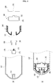
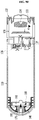
- a liquid medicine injection apparatus 100 capable of injecting an additional fluid after completion of injection of a liquid medicine according to this embodiment includes a cylinder 110, a piston 140, an injector, a fluid tank 160, a needle unit 170 and a cap member 180.
- the cylinder 110 is elongated in a direction and has a nozzle 111 formed at one end of the cylinder. More specifically, the cylinder 110 is formed in a generally cylindrical shape and its end at which the nozzle 111 is formed is curved to be generally convex outwardly. The nozzle 111 is formed at a central region of the end of the cylinder 110. One end of a tube (not shown) is inserted into and coupled to the nozzle 111. An end cap (not shown) may be provided at the other end of the tube (not shown), and an injection needle or a catheter (not shown) may be connected to the end cap.
- the nozzle 111 may extend in the shape of a truncated cone in a direction toward an inside of the cylinder 110.
- the nozzle is not limited thereto.
- the cylinder 110 is provided with the injector installed at the other end of the cylinder so as to move the piston 140.
- Any injector may be used without limitation so far as it has a configuration capable of moving a piston in a manual injection apparatus or an automatic injection apparatus, for example, a mechanical injection apparatus, a balloon type injection apparatus or a gas-generating type injection apparatus.
- the injector will be described in connection with the gas-generating type injection apparatus, although it is not limited thereto. A detailed description of the injector will be made later.
- the piston 140 is hermetically movable within the cylinder 110 in a direction and can define a liquid medicine storage space 114 in an internal space of the cylinder, wherein the liquid medicine storage space is filled with a liquid medicine introduced through the nozzle 111.
- the piston 140 defines a gas-supplied space 116 to which a gas generated in a gas-generating unit 130 to be described later is supplied.
- sealing ring insertion grooves 146a and 146b are formed between ring-shaped protrusions on a circumference of the piston 140, and sealing rings 144a and 144b are fitted into and coupled to the sealing ring insertion grooves 146a and 146b, respectively.
- the piston 140 can be hermetically moved within the cylinder 110 by these sealing rings 144a and 144b.
- the gas-generating unit 130 is largely composed of a body part 131 and a cap part 132.
- the gas-generating unit 130 accommodates a liquid material L and a solid material 134, wherein the liquid material L is accommodated in the body part 131 and the solid material is accommodated in the cap part 132.
- the solid material 134 is separated from the liquid material L by a partition wall 133 and is accommodated in the cap part 132.
- the solid material 134 may be pellets including sodium carbonate (Na 2 CO 3 ) as a main component and the liquid material L may be an acidic liquid material such as citric acid that generates carbon dioxide upon reaction thereof with the solid material 134.
- the liquid material L is accommodated by a gas permeable/liquid impermeable filter (not shown) provided on a circumference and a bottom of the body part 131, and the liquid material L does not flow into the gas-supplied space 116 of the cylinder 110 due to a liquid sealing function of this filter.
- a gas permeable/liquid impermeable filter (not shown) provided on a circumference and a bottom of the body part 131, and the liquid material L does not flow into the gas-supplied space 116 of the cylinder 110 due to a liquid sealing function of this filter.
- the partition wall 133 is detached due to an external force exerted on the cap part 132 and the solid material 134 falls into the body part 131, the solid material reacts with the liquid material L to generate a gas, i.e., carbon dioxide.
- the generated gas passes through the gas permeable/liquid impermeable filter in the body part 131 and is discharged into the gas-supplied space 116 of the cylinder 110, thereby pushing
- a function of successively injecting a second liquid medicine after completion of injection of a first liquid medicine can be implemented in a single apparatus.
- the two kinds of liquid medicines can be sequentially injected by means of a single apparatus.
- a small amount of the anticancer drugs or the analgesics remains in the cylinder 110 and/or in a tube (not shown) inserted in and connected to the nozzle 111.
- the fluid tank 160 can store a fluid in a hermitic state, is movably disposed within the cylinder 110 and is deformable by a pressure of the injector.
- This fluid tank 160 may be made of a flexible plastic material.
- the fluid tank 160 since the fluid tank 160 is sealed in a state where the fluid is stored therein, the fluid tank is not deformed even though a considerable pressure is exerted thereon by the injector. However, when a needle 172 to be described later penetrates the fluid tank 160, the fluid tank 160 is deformed to discharge the fluid stored therein. At this time, a pressure at which the fluid tank 160 is deformed may be higher than that required to inject the liquid medicine into the patient's body.
- the fluid may be a second liquid medicine different from the first liquid medicine with which the liquid medicine storage space 114 is filled.
- the fluid may be another anticancer drug that is used jointly with the first liquid medicine that is an anticancer drug.
- the fluid in the present invention is not limited thereto.
- the fluid may be a flushing fluid, for example, a saline solution.
- the fluid is not limited thereto and may be composed of a substance that does not affect a human body upon injection thereof.
- the fluid tank 160 will be described in greater detail.
- the fluid tank 160 generally has a cylindrical shape. More specifically, two flat circular plates are spaced apart from each other generally in parallel. Here, the two circular plates will be described as an upper plate and a lower plate.
- the needle 172 penetrates the upper plate of the fluid tank 160.
- the upper plate is disposed within the piston 140 as described below, the upper plate is disposed on the side of the nozzle 111.
- the lower plate of the fluid tank 160 includes a receiving portion 162 for receiving the needle 172 when the needle 172 completely penetrates the fluid tank.
- the receiving portion 162 protrudes outwardly from the fluid tank 160 and is generally formed to have a cup shape such that a hollow is defined therein.
- the fluid tank 160 includes a side portion connecting the upper plate and the lower plate.
- the side portion of the fluid tank 160 may be deformed when it is subjected to a pressure.
- the fluid tank includes a bellows 161 to be easily deformed, to be linearly deformed or to allow for prediction of a deformation direction.
- a portion of the fluid tank 160 which is disposed radially with respect to the direction, i.e., the side portion may be formed of a bellows 161.
- the fluid tank 160 is formed of two opposite flat circular plates and the bellows 161 connecting these plates but is not limited thereto.
- the fluid tank 160 may discharge the fluid stored therein through the needle 172.
- This fluid tank 130 may be installed within the piston 140.
- the inside of the piston 140 is empty, one end of the piston on the side of the nozzle 111 is closed and the other end is opened.
- the fluid tank 160 may be inserted into the piston 140 via the opened end of the piston 140.
- surfaces of the flat circular plates of the fluid tank 160 are arranged approximately perpendicular to the direction, and the side portion of the fluid tank 160 formed of the bellows 161 is radially disposed with respect to the direction.
- the fluid tank 160 can be moved together with the piston 140 by the injector.
- the needle unit 170 is disposed between the nozzle 111 and the fluid tank 160, and can penetrate the fluid tank 160 to communicate the nozzle 111 and the fluid tank 160 with each other. More specifically, the needle unit 170 includes a nozzle cap 171 capable of surrounding the nozzle 111 that extends into the liquid medicine storage space 114, and the needle 172 secured to the nozzle cap 171.
- the nozzle cap 171 is in the shape of a cup. That is, the nozzle cap 171 is generally formed to have a truncated conical shape and configured such that one end of the nozzle cap is opened and the other end thereof is closed. At this time, the needle 172 is fixed to a central region of the closed end of the nozzle cap 171. The nozzle 111 can be inserted into the opened end of the nozzle cap 171.
- the needle 172 may be in the shape of a tube to communicate the inside and the outside of the nozzle cap 171 with each other.
- the needle 172 may be formed to have a sharpened end to penetrate the fluid tank 160. Therefore, the fluid (for example, a second liquid medicine or a saline solution) stored in the fluid tank 160 can flow into the nozzle 111 along the inside of the needle 171 that has penetrated the fluid tank 160.
- the fluid tank 160 is required to maintain its configuration such that the fluid and the liquid medicine are not mixed with each other when the liquid medicine stored in the cylinder 110 is injected into the patient's body. Furthermore, the fluid tank 160 is required to discharge the stored fluid (a second liquid medicine or a saline solution) after the injection of the first liquid medicine into the patient's body is completed. Thus, the needle 172 penetrates the fluid tank 160 after the injection of the liquid medicine into the patient's body is completed.
- the cap member 180 is provided between the needle unit 170 and the fluid tank 160.
- the cap member 180 maintains a predetermined gap between the needle unit and the fluid tank so that the needle unit 170 may not penetrate a portion of the fluid tank 160, and the cap member is deformed such that the needle unit 170 penetrates the fluid tank 160 when a pressure that is not less than a predetermined pressure is exerted on the cap member.
- the predetermined pressure may be a pressure corresponding to an excess pressure, by which a pressure generated by the injector (for example, a pressure in the gas-supplied space 116) exceeds a pressure in the liquid medicine storage space 114, or may be a pressure higher than a pressure necessary for the liquid medicine injection apparatus 1000 to inject the liquid medicine into the patient's body through the nozzle 111.
- the cap member 180 before the predetermined pressure is exerted on the cap member by the injector (i.e., before completion of the injection of the first liquid medicine), the cap member 180 is not deformed to maintain the predetermined gap, thereby keeping the needle 172 from penetrating the fluid tank 160.
- the cap member 180 is deformed to expose the needle 172, thereby causing the needle 172 to penetrate the fluid tank 160.
- the cap member 180 may house the nozzle cap 171 and the needle 172 therein.
- the cap member 180 is generally formed to be in the shape of a cup slightly larger than the nozzle cap 171. Therefore, while the injection of the liquid medicine is initiated or the liquid medicine is being injected, the cap member 180 accommodates the needle unit 170 such that the needle 172 is not exposed, i.e., the needle 172 does not come into contact with the fluid tank 160.
- a portion of the cap member 180 surrounding the needle 172 is formed of a bellows 181 so as to be stably deformed when the predetermined pressure is exerted thereon. More specifically, a portion of a surface of the cap member 180 placed radially with respect to the direction, which is a portion of the cap member 180 adjacent to the needle 172 when the cap member 180 is disposed in the cylinder 110, is formed of the bellows 181.
- the aforementioned predetermined pressure is a pressure at which the bellows 181 of the cap member 180 is deformed.
- a portion of the fluid tank may be exposed to an outside, for example, to the gas-supplied space 116.
- the fluid tank 160 may not be evenly pressed directly by the injector. Therefore, a pressure plate 190 made of a material harder than the fluid tank 160 can be brought into contact with the lower plate of the fluid tank 160 to evenly press the fluid tank 160.
- the pressure plate 190 may further include a hole 191 into which the receiving portion 162 of the fluid tank 160 is inserted.
- the pressure plate 190 may also prevent the fluid tank 160 from being damaged.
- the needle unit 170, the cap member 180, the piston 140, the fluid tank 160 and the pressure plate 190 are disposed within the cylinder 110 in this order.
- the piston 140 has a hollow portion 141 formed in the direction, and the cap member 180 is fitted into the hollow portion 141.
- the hollow portion 141 of the piston 140 is generally in the shape of a truncated cone with a diameter decreased toward a side opposite to the nozzle 111.
- the cap member 180 is configured such that a portion thereof which is in contact with the piston 140 corresponds to an internal shape of the hollow portion 141 of the piston 140.
- the bellows 181 of the cap member 180 is disposed within the piston 140 and is larger than the diameter of the hollow portion 141 to prevent the cap member 180 from being inadvertently detached from the piston 140.
- the nozzle cap 171 of the needle unit 170 is inserted/press-fitted into the cap member 180.
- An external shape of the nozzle cap 171 corresponds to an internal shape of the cap member 180. Therefore, the nozzle cap 171 is not inadvertently detached from the cap member 180 due to a frictional force between the nozzle cap 171 and the cap member 180 or an elastic force between the cap member 180 and the nozzle cap 171.
- the needle 172 is located within the bellows 181 of the cap member 180 and does not protrude out of the cap member 180.
- the fluid tank 160 is disposed within the piston 140, wherein the upper plate of the fluid tank is disposed to face the needle 172 and the bellows 161 is disposed to face an inner circumference surface of the piston 140.
- the pressure plate 190 is installed at the piston 140 or secured to the fluid tank 160.
- the needle unit 170, the cap member 180, the fluid tank 160 and the pressure plate 190 are moved together with the piston 140 in the cylinder 110.
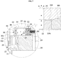
- the injector as a gas generator includes the gas-generating unit 130, an internal pressure-adjusting member 136 and the like (see portion "A" in FIG. 2 ).
- the internal pressure-adjusting member 136 is provided at the gas-generating unit 130 to face toward the inside of the gas-supplied space 116 of the cylinder 110 (see FIG. 1 ).
- This internal pressure-adjusting member 136 has an internal connection passage 220 for connecting an external air entrance 135 formed at one side of the body part 131 of the gas-generating unit 130 to the gas-supplied space 116, and a shut-off valve 320 which is hermetically moveable in the internal connection passage 220 and divides the internal connection passage 220 into an external air inflow space 222 into which external air can flow from the external air entrance 135 and a generated-gas inflow space 224 into which the gas from the gas-generating unit 130 flows.
- the external air entrance 135 is connected to the internal connection passage 220 through an air inflow passage 200.
- the shut-off valve 320 when the liquid medicine storage space is filled with the liquid medicine prior to the generation of the gas in the gas-generating unit 130, the shut-off valve 320 is positioned at a location where external air from the external air entrance 135 is caused to flow into the external air inflow space 222 and the external air inflow space 222 is in communication with the gas-supplied space 116, thereby equilibrating the internal pressure of the gas-supplied space 116 to an atmospheric pressure.
- the piston 140 separating the liquid medicine storage space 114 from the gas-supplied space 116 minimizes its pushing action interrupting a flow of the liquid medicine introduced into the liquid medicine storage space 114, i.e., a liquid medicine inflow resistance due to the piston 140, thereby facilitating the filling of the liquid medicine storage space with the liquid medicine.
- the shut-off valve 320 is moved toward the external air inflow space 222 by a propulsive force of the gas flowing from the gas-generating unit 130 into the generated-gas inflow space 224, thereby blocking inflow of external air from the external air entrance 135 into the external air inflow space 222.
- a high pressure of the gas generated by the gas-generating unit 130 is exerted on the piston 140 in the gas-supplied space 116 so that the piston 140 may be efficiently moved forward and the liquid medicine stored in the liquid medicine storage space 114 may be stably and continuously injected into the patient's body at a constant flow rate.
- the shut-off valve 320 may have a front end 322 facing toward the external air inflow space 222, and a body part 324 hermetically movable along a guide wall 242 of the internal connection passage 220, and may be formed with a through passage 327 extending from a through hole 326 of the front end 322 to a through hole 328 formed in a side surface of the body part 324.
- a through hole 240 for communicating the internal connection passage 220 with the gas-supplied space 116 may be formed in the guide wall 242 of the internal connection passage 220.
- the through hole 328 formed in the side surface of the body part 324 of the shut-off valve is fixed at a position where the through hole 328 is aligned with the through hole 240 of the internal connection passage. Therefore, external air introduced into the external air inflow space 222 flows through the through hole 326 of the front end 322, the through passage 327 and the through hole 328 of the body part 324 of the shut-off valve, and flows into the gas-supplied space 116 through the through hole 240 of the internal connection passage, which is aligned with the through hole 328 of the body part 324.
- an end of the external air inflow space 222 of the internal connection passage 220 may be opened and a sealing member 380 may be further included to seal this opened end.
- the sealing member 380 may be composed of a stepped sealing cap 382 and a rubber packing member 384 that is fitted into and coupled with a concave receiving portion 382a of such sealing cap.
- a tension spring 360 and the shut-off valve 320 are sequentially housed in the internal connection passage 220 through the opened end.
- a stepped portion 382b of the sealing cap is inserted into and tightly coupled with the opened end of the external air inflow space 222, and the rubber packing member 384 faces the external air inflow space 222.
- the gas generated in the gas-generating unit flows into the generated-gas inflow space 224 through a gas-flowing passage 260, which connects the body part 131 of the gas-generating unit 130 and the generated-gas inflow space 224, so as to push a rear portion of the body part 324 of the shut-off valve 320.
- the shut-off valve 320 is moved toward the external air inflow space 222 so that the front end 322 of the shut-off valve 320 is brought into contact with the sealing member 380 (See FIG. 8 ).
- This configuration prevents external air from the external air entrance 135 and the air inflow passage 200 from flowing into the through passage 327 of the shut-off valve 320 via the through hole 326 formed on the front end 322 of the shut-off valve 320.
- the front end 322 of the shut-off valve 320 presses and is in contact with the rubber packing member 384 constituting the sealing member 380, the front end 322 of the shut-off valve 320 is in close contact with the rubber packing member 384 and is blocked so that it is possible to reliably prevent external air from leaking via the through hole 326 formed on the front end 322 of the shut-off valve 320.
- a plurality of ring-shaped protrusions preferably at least two, and more preferably four ring-shaped protrusions 3240a, 3240b, 3240c and 3240d may be formed on a circumference of the body part 324 of the shut-off valve 320.
- At least one protrusion 3240c of the ring-shaped protrusions is in close contact with a gentle stepped portion 1362 formed on the guide wall 242 of the internal connection passage 220.
- shut-off valve 320 Before the gas generated in the gas-generating unit 130 is introduced into the generated-gas inflow space 224, it is possible to securely fix the shut-off valve 320 at a location where the through hole 328 formed in the side surface of the body part 324 of the shut-off valve 320 is aligned with the through hole 240 of the internal connection passage (see FIG. 7 ).
- the pressure of the introduced gas is exerted on a rear portion of the body part 324 of the shut-off valve 320 so that the shut-off valve 320 may overcome an obstacle to a movement, which is caused by engagement of the ring-shaped protrusion 3240c with the stepped portion 1362, and be moved toward the external air inflow space 222 (see FIG. 8 ).
- the shut-off valve 320 it is possible to prevent the shut-off valve 320 from being moved due to temporary external impact or external air, so that the internal pressure of the gas-supplied space 116 is stably equilibrated to the atmospheric pressure before the gas is generated in the gas-generating unit, whereas upon generation of the gas in the gas-generating unit, the gas pressure generated in response to a liquid medicine injection mode enables the shut-off valve 320 to overcome an obstacle to a movement, which is caused by the stepped portion 1362, and to be moved toward the external air inflow space 222, and the front end 322 of the shut-off valve 320 is in close contact with the sealing member 380 to block the inflow of external air.
- each of sealing rings 340a or 340b can be inserted between the pair of two ring-shaped protrusions 3240a and 3240b or 3240c and 3240d.
- the sealing rings 340a and 340b allow the shut-off valve 320 to be hermetically moved along the guide wall 242 of the internal connection passage 220.
- the liquid medicine injection apparatus 1000 of the embodiment of the present invention may further include the tension spring 360 fixedly installed in the generated-gas inflow space 224 and coupled to the body part 324 of the shut-off valve 320.
- the gas pressure generated in response to the liquid medicine injection mode enables the shut-off valve 320 to overcome the elastic restoring force caused by the tension spring 360 and to be moved toward the external air inflow space 222, and the front end 322 of the shut-off valve 320 is in close contact with the sealing member 380 to block the inflow of external air.
- the tension spring 360 prevents the shut-off valve 320 from being moved due to temporary external impact or external air by means of the elastic restoring force, thereby assisting in attaining a stable equilibrium between the internal pressure of the gas-supplied space 116 and the atmospheric pressure before the gas is generated in the gas-generating unit.
- the elastic restoring force of the tension spring helps to return the shut-off valve 320 to its original state where the injection of the liquid medicine is not initiated.
- the external air entrance 135 may be provided with a gas-permeable/liquid-impermeable hydrophobic filter (not shown).
- a gas-permeable/liquid-impermeable hydrophobic filter allows external air to flow into the apparatus through the external air entrance 135, but prevents water, a liquid medicine, a liquid contaminant and the like from flowing into the apparatus from the outside.
- the hydrophobic filter those disclosed in prior arts or known in the art may be employed.
- the elements constituting the liquid medicine injection apparatus 1000 are formed of a material suitable for withstanding external impact and may be formed of a plastic material, a synthetic resin or the like that have been well known in the art.
- the sealing rings 340a and 340b and the rubber packing member 384 may be formed of a known elastic rubber material.
- plastic or spring steel may be used as a material for the tension spring 360.
- the present invention is not limited thereto and the aforementioned elements may be formed of various materials well known in the art, wherein the materials meet the object of the present invention, satisfy biocompatibility, are less corroded and have predetermined durability.
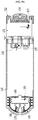
- FIG. 9A schematically illustrates a state before the liquid medicine injection apparatus 1000 is filled with the liquid medicine.
- the piston 140 is coupled to the needle 170, the cap member 180, the fluid tank 160 and the pressure plate 190 as described above and is disposed adjacent to the nozzle 111.
- the nozzle 111 is placed within the nozzle cap 171 of the needle unit 170.
- the piston 140 is moved toward the gas-generating unit 130 as the liquid medicine storage space is filled with the liquid medicine.
- the needle unit 170, the cap member 180, the fluid tank 160 and the pressure plate 190 coupled to the piston 140 are also moved together.
- the cap member 180 is not pressed under the predetermined pressure. Specifically, even when the pressure in the liquid medicine storage space 114 is increased, the pressure in the gas-supplied space 116 is low and the piston 140 is moved toward the gas-supplied space 116, so that the cap member 180 is not pressed by the pressure at which the cap member is deformed (the predetermined pressure). Further, since the fluid tank 160 is in a sealed state, it is not deformed by the pressure.
- the partition wall 133 is removed to fall the solid material 134 into the liquid material so that the solid material and the liquid material are reacted with each other to generate the gas.
- the piston 140 is moved toward the nozzle to inject the liquid medicine in the liquid medicine storage space 114 into the patient's body.
- the cap member 180 is subjected to a pressure lower than the pressure at which the cap member is deformed (the predetermined pressure). In other words, the bellows 181 of the cap member 180 is not pressed by the fluid tank 160. Since the needle 172 does not penetrate the fluid tank 160, the fluid tank 160 keeps its outer shape even though it is subjected to the pressure.
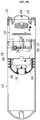
- This predetermined pressure deforms the cap member 180. That is, the cap member 180 is pressed under the predetermined pressure, and the bellows 181 of the cap member 180 is pressed by the fluid tank 160.
- the needle 172 is exposed to the outside of the cap member 180 and penetrates the fluid tank 160. Then, the fluid (a second liquid medicine or a saline solution) stored in the fluid tank 160 flows out through the needle 172. At this time, the pressure plate 190 can evenly transmit the pressure of the gas to the fluid tank 160.
- FIG. 9D illustrates a process of causing the fluid tank 160 to be compressed by the pressure of the gas.
- the fluid a second liquid medicine or a saline solution
- the second liquid medicine in the fluid tank 160 is successively injected after completion of the injection of the first liquid medicine in the liquid medicine storage space 114.
- a flushing fluid for example, a saline solution
- the saline solution flushes the nozzle 111 and/or a tube (not shown) inserted into the nozzle 111 to wash away the liquid medicine remaining in the nozzle and/or the tube and inject it into the patient's body.
- the receiving portion 162 enables the needle 172 to supply the fluid (a second liquid medicine or a saline solution) without being clogged until the fluid tank 160 is fully compressed.
- the amount of the second liquid medicine injected into the patient's body is a dose required according to a therapeutic regimen.
- the amount of the saline solution is an amount that does not adversely affect patient health when it is injected into the patient's body and is sufficient to wash away the liquid medicine remaining in the nozzle and/or the tube.
- the second liquid medicine can be successively injected after completion of the injection of the first liquid medicine by means of the aforementioned operation by using a single apparatus.
- the apparatus of the present invention can solve problems due to the residual liquid medicine in the liquid medicine injection apparatus and/or in the tube, for example, environmental problems and illegal distribution of dangerous drugs.
Applications Claiming Priority (2)
| Application Number | Priority Date | Filing Date | Title |
|---|---|---|---|
| KR1020160097783A KR101785902B1 (ko) | 2016-08-01 | 2016-08-01 | 약액 주입 완료 후 추가 유체의 주입이 가능한 약액주입장치 |
| PCT/KR2017/007928 WO2018026130A1 (ko) | 2016-08-01 | 2017-07-24 | 약액 주입 완료 후 추가 유체의 주입이 가능한 약액주입장치 |
Publications (3)
| Publication Number | Publication Date |
|---|---|
| EP3492127A1 EP3492127A1 (en) | 2019-06-05 |
| EP3492127A4 EP3492127A4 (en) | 2020-01-08 |
| EP3492127B1 true EP3492127B1 (en) | 2021-01-27 |
Family
ID=60297982
Family Applications (1)
| Application Number | Title | Priority Date | Filing Date |
|---|---|---|---|
| EP17837182.9A Active EP3492127B1 (en) | 2016-08-01 | 2017-07-24 | Liquid medicine injection apparatus capable of injecting additional fluid after completion of liquid medicine injection |
Country Status (8)
| Country | Link |
|---|---|
| US (1) | US10940268B2 (ko) |
| EP (1) | EP3492127B1 (ko) |
| JP (1) | JP6853874B2 (ko) |
| KR (1) | KR101785902B1 (ko) |
| CN (1) | CN109843359B (ko) |
| ES (1) | ES2862318T3 (ko) |
| IL (1) | IL264569B (ko) |
| WO (1) | WO2018026130A1 (ko) |
Families Citing this family (7)
| Publication number | Priority date | Publication date | Assignee | Title |
|---|---|---|---|---|
| KR102051435B1 (ko) * | 2018-12-07 | 2019-12-03 | 주식회사 엘지화학 | 알러지 진단용 칩 제조 장치 |
| US20240082483A1 (en) * | 2019-11-01 | 2024-03-14 | Yong Hyun Kim | Medicinal liquid pushing apparatus and medicinal liquid injection apparatus including same |
| WO2022045653A1 (ko) * | 2020-08-25 | 2022-03-03 | 김용현 | 약액 펌핑 장치 및 이를 이용한 약액 주입 준비방법 |
| CN112426364B (zh) * | 2020-12-01 | 2021-08-24 | 吉林大学 | 一种癌症患者用化疗药品注射渗出处理仪 |
| KR102599610B1 (ko) * | 2021-08-12 | 2023-11-08 | 김용현 | 약액 주입 장치 |
| WO2023163378A1 (ko) * | 2022-02-23 | 2023-08-31 | 김용현 | 공기 충전형 약액 펌핑 장치, 약액 주입 장치 및 공기 충전형 약액 펌핑 장치의 제조 방법 |
| WO2023163244A2 (ko) * | 2022-02-23 | 2023-08-31 | 김용현 | 약액 펌핑 모듈 및 이를 이용한 약액 주입 준비방법 |
Family Cites Families (19)
| Publication number | Priority date | Publication date | Assignee | Title |
|---|---|---|---|---|
| GB770341A (en) | 1954-11-18 | 1957-03-20 | Russell Paul Dunmire | Hypodermic syringe |
| US5637087A (en) * | 1995-03-22 | 1997-06-10 | Abbott Laboratories | Prefilled, two-constituent syringe |
| KR200234119Y1 (ko) * | 1999-05-14 | 2001-09-25 | 정인근 | 의약품 주입장치 |
| WO2001000261A1 (en) * | 1999-06-30 | 2001-01-04 | Baxter International Inc. | Syringe for transfer of medication from a prefilled medication container |
| CN1676169B (zh) | 2000-07-22 | 2011-12-28 | 株式会社费森尤斯卡比 | 液体供给设备 |
| US7621887B2 (en) | 2000-10-10 | 2009-11-24 | Meridian Medical Technologies, Inc. | Wet/dry automatic injector assembly |
| KR100507593B1 (ko) | 2002-02-08 | 2005-08-10 | 주식회사 이화양행 | 액체공급장치 |
| US6723074B1 (en) * | 2002-04-09 | 2004-04-20 | Thor R. Halseth | Sequential delivery syringe |
| JP4902096B2 (ja) * | 2003-07-10 | 2012-03-21 | 株式会社根本杏林堂 | 薬液シリンジ |
| JP2005110735A (ja) * | 2003-10-03 | 2005-04-28 | Keizo Tanii | 薬液充填用タンデム型2層化シリンジ製剤 |
| US20100286513A1 (en) * | 2008-01-23 | 2010-11-11 | Pollard Jr Ralph E | Plunger Adapter for Coaxial Syringe System |
| JP5943931B2 (ja) * | 2010-11-03 | 2016-07-05 | サノフィ−アベンティス・ドイチュラント・ゲゼルシャフト・ミット・ベシュレンクテル・ハフツング | 折り畳み機能を有する薬用モジュール |
| WO2012059450A1 (en) * | 2010-11-03 | 2012-05-10 | Sanofi-Aventis Deutschland Gmbh | Medicated module with deformable membrane |
| KR101121082B1 (ko) | 2011-03-10 | 2012-03-16 | 주식회사 메가젠임플란트 | 약물 주입 장치 |
| US20150032063A1 (en) * | 2011-05-13 | 2015-01-29 | Gale Harrison Thorne | Components and devices for closed medical system operation |
| KR101377987B1 (ko) * | 2012-04-13 | 2014-03-24 | 메디허브주식회사 | 자동주사기 |
| EP2906270B1 (en) * | 2012-10-15 | 2018-05-30 | Elcam Medical Agricultural Cooperative Association Ltd. | Multi-chamber syringe |
| KR101397129B1 (ko) * | 2012-10-29 | 2014-05-19 | 신경수 | 약액 주사장치 |
| JP6588687B2 (ja) | 2013-12-10 | 2019-10-09 | 株式会社根本杏林堂 | 薬液注入システム |
-
2016
- 2016-08-01 KR KR1020160097783A patent/KR101785902B1/ko active IP Right Grant
-
2017
- 2017-07-24 WO PCT/KR2017/007928 patent/WO2018026130A1/ko unknown
- 2017-07-24 US US16/322,388 patent/US10940268B2/en active Active
- 2017-07-24 JP JP2019505392A patent/JP6853874B2/ja active Active
- 2017-07-24 EP EP17837182.9A patent/EP3492127B1/en active Active
- 2017-07-24 ES ES17837182T patent/ES2862318T3/es active Active
- 2017-07-24 CN CN201780060720.9A patent/CN109843359B/zh active Active
-
2019
- 2019-01-31 IL IL264569A patent/IL264569B/en unknown
Non-Patent Citations (1)
| Title |
|---|
| None * |
Also Published As
| Publication number | Publication date |
|---|---|
| IL264569A (en) | 2019-02-28 |
| US20190192775A1 (en) | 2019-06-27 |
| EP3492127A1 (en) | 2019-06-05 |
| JP6853874B2 (ja) | 2021-03-31 |
| JP2019523095A (ja) | 2019-08-22 |
| CN109843359B (zh) | 2021-07-27 |
| US10940268B2 (en) | 2021-03-09 |
| KR101785902B1 (ko) | 2017-10-17 |
| CN109843359A (zh) | 2019-06-04 |
| IL264569B (en) | 2022-06-01 |
| EP3492127A4 (en) | 2020-01-08 |
| ES2862318T3 (es) | 2021-10-07 |
| WO2018026130A1 (ko) | 2018-02-08 |
Similar Documents
| Publication | Publication Date | Title |
|---|---|---|
| EP3492127B1 (en) | Liquid medicine injection apparatus capable of injecting additional fluid after completion of liquid medicine injection | |
| US6682504B2 (en) | Single use disposable jet injector | |
| ES2407305T3 (es) | Insertos de la trayectoria de flujo para inyectores automáticos húmedos/secos | |
| KR940006107B1 (ko) | 자동약제성분 혼합 및 주사장치 | |
| KR100799731B1 (ko) | 습식/건식 자동주사기조립체 | |
| JP3718167B2 (ja) | 充填済みアンプル内に入った液体を注入するための無針式シリンジ | |
| ES2230201T3 (es) | Jeringa hipodermica con aguja selectivamente retractil. | |
| KR20040096561A (ko) | 바이패스 채널을 구비한 주사기 | |
| CN109758667A (zh) | 药剂装置 | |
| CN109125861A (zh) | 用于输送流体的装置 | |
| EA004097B1 (ru) | Медицинское устройство | |
| WO2003075986A1 (fr) | Outil d'extraction | |
| JP2009532151A (ja) | 薬剤を高圧により送達するための無針注射システム | |
| JP2018505747A (ja) | シリンジシステム、ピストンシールシステム、ストッパシステム、並びに使用及び組み立て方法 | |
| US20200360235A1 (en) | A valve for an injection device and an injection device with such a valve | |
| CN101801444B (zh) | 供给装置 | |
| KR101137711B1 (ko) | 최적화된 주사기-수용구를 포함하는 무침 주사기 | |
| KR101697980B1 (ko) | 약액 충전 및 주입 모드에 따라 내부압력 조절이 가능한 약액주입장치 | |
| EP3434299B1 (en) | Medicinal fluid injection device capable of adjusting internal pressure | |
| KR102194354B1 (ko) | 약액주입장치 | |
| JP2008099728A (ja) | 容器兼用注射器 | |
| KR101313632B1 (ko) | 무침 주사기 | |
| JP7482789B2 (ja) | 2種類以上の流体を独立して送達するためのデュアルステージ注射器 | |
| WO2019149328A1 (en) | A valve for an injection device and an injection device with such a valve | |
| RU2775428C1 (ru) | Инъектор лекарственных растворов, содержащий счетчик болюсных инъекций |
Legal Events
| Date | Code | Title | Description |
|---|---|---|---|
| STAA | Information on the status of an ep patent application or granted ep patent |
Free format text: STATUS: THE INTERNATIONAL PUBLICATION HAS BEEN MADE |
|
| PUAI | Public reference made under article 153(3) epc to a published international application that has entered the european phase |
Free format text: ORIGINAL CODE: 0009012 |
|
| STAA | Information on the status of an ep patent application or granted ep patent |
Free format text: STATUS: REQUEST FOR EXAMINATION WAS MADE |
|
| 17P | Request for examination filed |
Effective date: 20190301 |
|
| AK | Designated contracting states |
Kind code of ref document: A1 Designated state(s): AL AT BE BG CH CY CZ DE DK EE ES FI FR GB GR HR HU IE IS IT LI LT LU LV MC MK MT NL NO PL PT RO RS SE SI SK SM TR |
|
| AX | Request for extension of the european patent |
Extension state: BA ME |
|
| DAV | Request for validation of the european patent (deleted) | ||
| DAX | Request for extension of the european patent (deleted) | ||
| A4 | Supplementary search report drawn up and despatched |
Effective date: 20191211 |
|
| RIC1 | Information provided on ipc code assigned before grant |
Ipc: A61M 5/315 20060101AFI20191205BHEP Ipc: A61M 5/178 20060101ALI20191205BHEP Ipc: A61M 5/32 20060101ALI20191205BHEP Ipc: A61M 5/19 20060101ALI20191205BHEP Ipc: A61M 5/28 20060101ALI20191205BHEP Ipc: A61M 5/14 20060101ALI20191205BHEP |
|
| GRAP | Despatch of communication of intention to grant a patent |
Free format text: ORIGINAL CODE: EPIDOSNIGR1 |
|
| STAA | Information on the status of an ep patent application or granted ep patent |
Free format text: STATUS: GRANT OF PATENT IS INTENDED |
|
| INTG | Intention to grant announced |
Effective date: 20200901 |
|
| GRAS | Grant fee paid |
Free format text: ORIGINAL CODE: EPIDOSNIGR3 |
|
| GRAA | (expected) grant |
Free format text: ORIGINAL CODE: 0009210 |
|
| STAA | Information on the status of an ep patent application or granted ep patent |
Free format text: STATUS: THE PATENT HAS BEEN GRANTED |
|
| AK | Designated contracting states |
Kind code of ref document: B1 Designated state(s): AL AT BE BG CH CY CZ DE DK EE ES FI FR GB GR HR HU IE IS IT LI LT LU LV MC MK MT NL NO PL PT RO RS SE SI SK SM TR |
|
| REG | Reference to a national code |
Ref country code: GB Ref legal event code: FG4D |
|
| REG | Reference to a national code |
Ref country code: CH Ref legal event code: EP |
|
| REG | Reference to a national code |
Ref country code: AT Ref legal event code: REF Ref document number: 1357772 Country of ref document: AT Kind code of ref document: T Effective date: 20210215 |
|
| REG | Reference to a national code |
Ref country code: IE Ref legal event code: FG4D |
|
| REG | Reference to a national code |
Ref country code: DE Ref legal event code: R096 Ref document number: 602017032265 Country of ref document: DE |
|
| REG | Reference to a national code |
Ref country code: CH Ref legal event code: NV Representative=s name: HEPP WENGER RYFFEL AG, CH |
|
| REG | Reference to a national code |
Ref country code: NL Ref legal event code: MP Effective date: 20210127 |
|
| REG | Reference to a national code |
Ref country code: LT Ref legal event code: MG9D |
|
| REG | Reference to a national code |
Ref country code: AT Ref legal event code: MK05 Ref document number: 1357772 Country of ref document: AT Kind code of ref document: T Effective date: 20210127 |
|
| PG25 | Lapsed in a contracting state [announced via postgrant information from national office to epo] |
Ref country code: LT Free format text: LAPSE BECAUSE OF FAILURE TO SUBMIT A TRANSLATION OF THE DESCRIPTION OR TO PAY THE FEE WITHIN THE PRESCRIBED TIME-LIMIT Effective date: 20210127 Ref country code: BG Free format text: LAPSE BECAUSE OF FAILURE TO SUBMIT A TRANSLATION OF THE DESCRIPTION OR TO PAY THE FEE WITHIN THE PRESCRIBED TIME-LIMIT Effective date: 20210427 Ref country code: PT Free format text: LAPSE BECAUSE OF FAILURE TO SUBMIT A TRANSLATION OF THE DESCRIPTION OR TO PAY THE FEE WITHIN THE PRESCRIBED TIME-LIMIT Effective date: 20210527 Ref country code: NO Free format text: LAPSE BECAUSE OF FAILURE TO SUBMIT A TRANSLATION OF THE DESCRIPTION OR TO PAY THE FEE WITHIN THE PRESCRIBED TIME-LIMIT Effective date: 20210427 Ref country code: HR Free format text: LAPSE BECAUSE OF FAILURE TO SUBMIT A TRANSLATION OF THE DESCRIPTION OR TO PAY THE FEE WITHIN THE PRESCRIBED TIME-LIMIT Effective date: 20210127 Ref country code: FI Free format text: LAPSE BECAUSE OF FAILURE TO SUBMIT A TRANSLATION OF THE DESCRIPTION OR TO PAY THE FEE WITHIN THE PRESCRIBED TIME-LIMIT Effective date: 20210127 Ref country code: GR Free format text: LAPSE BECAUSE OF FAILURE TO SUBMIT A TRANSLATION OF THE DESCRIPTION OR TO PAY THE FEE WITHIN THE PRESCRIBED TIME-LIMIT Effective date: 20210428 |
|
| PG25 | Lapsed in a contracting state [announced via postgrant information from national office to epo] |
Ref country code: AT Free format text: LAPSE BECAUSE OF FAILURE TO SUBMIT A TRANSLATION OF THE DESCRIPTION OR TO PAY THE FEE WITHIN THE PRESCRIBED TIME-LIMIT Effective date: 20210127 Ref country code: LV Free format text: LAPSE BECAUSE OF FAILURE TO SUBMIT A TRANSLATION OF THE DESCRIPTION OR TO PAY THE FEE WITHIN THE PRESCRIBED TIME-LIMIT Effective date: 20210127 Ref country code: RS Free format text: LAPSE BECAUSE OF FAILURE TO SUBMIT A TRANSLATION OF THE DESCRIPTION OR TO PAY THE FEE WITHIN THE PRESCRIBED TIME-LIMIT Effective date: 20210127 Ref country code: PL Free format text: LAPSE BECAUSE OF FAILURE TO SUBMIT A TRANSLATION OF THE DESCRIPTION OR TO PAY THE FEE WITHIN THE PRESCRIBED TIME-LIMIT Effective date: 20210127 Ref country code: SE Free format text: LAPSE BECAUSE OF FAILURE TO SUBMIT A TRANSLATION OF THE DESCRIPTION OR TO PAY THE FEE WITHIN THE PRESCRIBED TIME-LIMIT Effective date: 20210127 |
|
| PG25 | Lapsed in a contracting state [announced via postgrant information from national office to epo] |
Ref country code: IS Free format text: LAPSE BECAUSE OF FAILURE TO SUBMIT A TRANSLATION OF THE DESCRIPTION OR TO PAY THE FEE WITHIN THE PRESCRIBED TIME-LIMIT Effective date: 20210527 |
|
| REG | Reference to a national code |
Ref country code: ES Ref legal event code: FG2A Ref document number: 2862318 Country of ref document: ES Kind code of ref document: T3 Effective date: 20211007 |
|
| REG | Reference to a national code |
Ref country code: DE Ref legal event code: R097 Ref document number: 602017032265 Country of ref document: DE |
|
| PG25 | Lapsed in a contracting state [announced via postgrant information from national office to epo] |
Ref country code: EE Free format text: LAPSE BECAUSE OF FAILURE TO SUBMIT A TRANSLATION OF THE DESCRIPTION OR TO PAY THE FEE WITHIN THE PRESCRIBED TIME-LIMIT Effective date: 20210127 Ref country code: CZ Free format text: LAPSE BECAUSE OF FAILURE TO SUBMIT A TRANSLATION OF THE DESCRIPTION OR TO PAY THE FEE WITHIN THE PRESCRIBED TIME-LIMIT Effective date: 20210127 Ref country code: SM Free format text: LAPSE BECAUSE OF FAILURE TO SUBMIT A TRANSLATION OF THE DESCRIPTION OR TO PAY THE FEE WITHIN THE PRESCRIBED TIME-LIMIT Effective date: 20210127 |
|
| PG25 | Lapsed in a contracting state [announced via postgrant information from national office to epo] |
Ref country code: SK Free format text: LAPSE BECAUSE OF FAILURE TO SUBMIT A TRANSLATION OF THE DESCRIPTION OR TO PAY THE FEE WITHIN THE PRESCRIBED TIME-LIMIT Effective date: 20210127 Ref country code: DK Free format text: LAPSE BECAUSE OF FAILURE TO SUBMIT A TRANSLATION OF THE DESCRIPTION OR TO PAY THE FEE WITHIN THE PRESCRIBED TIME-LIMIT Effective date: 20210127 Ref country code: RO Free format text: LAPSE BECAUSE OF FAILURE TO SUBMIT A TRANSLATION OF THE DESCRIPTION OR TO PAY THE FEE WITHIN THE PRESCRIBED TIME-LIMIT Effective date: 20210127 |
|
| PLBE | No opposition filed within time limit |
Free format text: ORIGINAL CODE: 0009261 |
|
| STAA | Information on the status of an ep patent application or granted ep patent |
Free format text: STATUS: NO OPPOSITION FILED WITHIN TIME LIMIT |
|
| 26N | No opposition filed |
Effective date: 20211028 |
|
| PG25 | Lapsed in a contracting state [announced via postgrant information from national office to epo] |
Ref country code: AL Free format text: LAPSE BECAUSE OF FAILURE TO SUBMIT A TRANSLATION OF THE DESCRIPTION OR TO PAY THE FEE WITHIN THE PRESCRIBED TIME-LIMIT Effective date: 20210127 |
|
| PG25 | Lapsed in a contracting state [announced via postgrant information from national office to epo] |
Ref country code: SI Free format text: LAPSE BECAUSE OF FAILURE TO SUBMIT A TRANSLATION OF THE DESCRIPTION OR TO PAY THE FEE WITHIN THE PRESCRIBED TIME-LIMIT Effective date: 20210127 |
|
| PG25 | Lapsed in a contracting state [announced via postgrant information from national office to epo] |
Ref country code: MC Free format text: LAPSE BECAUSE OF FAILURE TO SUBMIT A TRANSLATION OF THE DESCRIPTION OR TO PAY THE FEE WITHIN THE PRESCRIBED TIME-LIMIT Effective date: 20210127 |
|
| REG | Reference to a national code |
Ref country code: BE Ref legal event code: MM Effective date: 20210731 |
|
| PG25 | Lapsed in a contracting state [announced via postgrant information from national office to epo] |
Ref country code: IS Free format text: LAPSE BECAUSE OF FAILURE TO SUBMIT A TRANSLATION OF THE DESCRIPTION OR TO PAY THE FEE WITHIN THE PRESCRIBED TIME-LIMIT Effective date: 20210527 Ref country code: LU Free format text: LAPSE BECAUSE OF NON-PAYMENT OF DUE FEES Effective date: 20210724 |
|
| PG25 | Lapsed in a contracting state [announced via postgrant information from national office to epo] |
Ref country code: IE Free format text: LAPSE BECAUSE OF NON-PAYMENT OF DUE FEES Effective date: 20210724 Ref country code: BE Free format text: LAPSE BECAUSE OF NON-PAYMENT OF DUE FEES Effective date: 20210731 |
|
| PG25 | Lapsed in a contracting state [announced via postgrant information from national office to epo] |
Ref country code: NL Free format text: LAPSE BECAUSE OF NON-PAYMENT OF DUE FEES Effective date: 20210127 Ref country code: CY Free format text: LAPSE BECAUSE OF FAILURE TO SUBMIT A TRANSLATION OF THE DESCRIPTION OR TO PAY THE FEE WITHIN THE PRESCRIBED TIME-LIMIT Effective date: 20210127 |
|
| PG25 | Lapsed in a contracting state [announced via postgrant information from national office to epo] |
Ref country code: HU Free format text: LAPSE BECAUSE OF FAILURE TO SUBMIT A TRANSLATION OF THE DESCRIPTION OR TO PAY THE FEE WITHIN THE PRESCRIBED TIME-LIMIT; INVALID AB INITIO Effective date: 20170724 |
|
| PGFP | Annual fee paid to national office [announced via postgrant information from national office to epo] |
Ref country code: IT Payment date: 20230724 Year of fee payment: 7 Ref country code: GB Payment date: 20230721 Year of fee payment: 7 Ref country code: ES Payment date: 20230927 Year of fee payment: 7 Ref country code: CH Payment date: 20230801 Year of fee payment: 7 |
|
| PGFP | Annual fee paid to national office [announced via postgrant information from national office to epo] |
Ref country code: FR Payment date: 20230726 Year of fee payment: 7 Ref country code: DE Payment date: 20230731 Year of fee payment: 7 |
|
| PG25 | Lapsed in a contracting state [announced via postgrant information from national office to epo] |
Ref country code: MK Free format text: LAPSE BECAUSE OF FAILURE TO SUBMIT A TRANSLATION OF THE DESCRIPTION OR TO PAY THE FEE WITHIN THE PRESCRIBED TIME-LIMIT Effective date: 20210127 |