EP3491237B1 - Scheibenbremse für einen bremsscheibenring eines azimutantriebs einer windkraftanlage - Google Patents
Scheibenbremse für einen bremsscheibenring eines azimutantriebs einer windkraftanlage Download PDFInfo
- Publication number
- EP3491237B1 EP3491237B1 EP17739284.2A EP17739284A EP3491237B1 EP 3491237 B1 EP3491237 B1 EP 3491237B1 EP 17739284 A EP17739284 A EP 17739284A EP 3491237 B1 EP3491237 B1 EP 3491237B1
- Authority
- EP
- European Patent Office
- Prior art keywords
- housing
- brake
- cleansing
- disk
- friction lining
- Prior art date
- Legal status (The legal status is an assumption and is not a legal conclusion. Google has not performed a legal analysis and makes no representation as to the accuracy of the status listed.)
- Active
Links
Images
Classifications
-
- F—MECHANICAL ENGINEERING; LIGHTING; HEATING; WEAPONS; BLASTING
- F03—MACHINES OR ENGINES FOR LIQUIDS; WIND, SPRING, OR WEIGHT MOTORS; PRODUCING MECHANICAL POWER OR A REACTIVE PROPULSIVE THRUST, NOT OTHERWISE PROVIDED FOR
- F03D—WIND MOTORS
- F03D7/00—Controlling wind motors
- F03D7/02—Controlling wind motors the wind motors having rotation axis substantially parallel to the air flow entering the rotor
- F03D7/0244—Controlling wind motors the wind motors having rotation axis substantially parallel to the air flow entering the rotor for braking
- F03D7/0248—Controlling wind motors the wind motors having rotation axis substantially parallel to the air flow entering the rotor for braking by mechanical means acting on the power train
-
- F—MECHANICAL ENGINEERING; LIGHTING; HEATING; WEAPONS; BLASTING
- F03—MACHINES OR ENGINES FOR LIQUIDS; WIND, SPRING, OR WEIGHT MOTORS; PRODUCING MECHANICAL POWER OR A REACTIVE PROPULSIVE THRUST, NOT OTHERWISE PROVIDED FOR
- F03D—WIND MOTORS
- F03D7/00—Controlling wind motors
- F03D7/02—Controlling wind motors the wind motors having rotation axis substantially parallel to the air flow entering the rotor
- F03D7/0204—Controlling wind motors the wind motors having rotation axis substantially parallel to the air flow entering the rotor for orientation in relation to wind direction
-
- F—MECHANICAL ENGINEERING; LIGHTING; HEATING; WEAPONS; BLASTING
- F03—MACHINES OR ENGINES FOR LIQUIDS; WIND, SPRING, OR WEIGHT MOTORS; PRODUCING MECHANICAL POWER OR A REACTIVE PROPULSIVE THRUST, NOT OTHERWISE PROVIDED FOR
- F03D—WIND MOTORS
- F03D7/00—Controlling wind motors
- F03D7/02—Controlling wind motors the wind motors having rotation axis substantially parallel to the air flow entering the rotor
- F03D7/0244—Controlling wind motors the wind motors having rotation axis substantially parallel to the air flow entering the rotor for braking
-
- F—MECHANICAL ENGINEERING; LIGHTING; HEATING; WEAPONS; BLASTING
- F03—MACHINES OR ENGINES FOR LIQUIDS; WIND, SPRING, OR WEIGHT MOTORS; PRODUCING MECHANICAL POWER OR A REACTIVE PROPULSIVE THRUST, NOT OTHERWISE PROVIDED FOR
- F03D—WIND MOTORS
- F03D80/00—Details, components or accessories not provided for in groups F03D1/00 - F03D17/00
- F03D80/50—Maintenance or repair
- F03D80/55—Cleaning
-
- F—MECHANICAL ENGINEERING; LIGHTING; HEATING; WEAPONS; BLASTING
- F16—ENGINEERING ELEMENTS AND UNITS; GENERAL MEASURES FOR PRODUCING AND MAINTAINING EFFECTIVE FUNCTIONING OF MACHINES OR INSTALLATIONS; THERMAL INSULATION IN GENERAL
- F16D—COUPLINGS FOR TRANSMITTING ROTATION; CLUTCHES; BRAKES
- F16D55/00—Brakes with substantially-radial braking surfaces pressed together in axial direction, e.g. disc brakes
- F16D55/02—Brakes with substantially-radial braking surfaces pressed together in axial direction, e.g. disc brakes with axially-movable discs or pads pressed against axially-located rotating members
- F16D55/22—Brakes with substantially-radial braking surfaces pressed together in axial direction, e.g. disc brakes with axially-movable discs or pads pressed against axially-located rotating members by clamping an axially-located rotating disc between movable braking members, e.g. movable brake discs or brake pads
- F16D55/224—Brakes with substantially-radial braking surfaces pressed together in axial direction, e.g. disc brakes with axially-movable discs or pads pressed against axially-located rotating members by clamping an axially-located rotating disc between movable braking members, e.g. movable brake discs or brake pads with a common actuating member for the braking members
- F16D55/225—Brakes with substantially-radial braking surfaces pressed together in axial direction, e.g. disc brakes with axially-movable discs or pads pressed against axially-located rotating members by clamping an axially-located rotating disc between movable braking members, e.g. movable brake discs or brake pads with a common actuating member for the braking members the braking members being brake pads
-
- F—MECHANICAL ENGINEERING; LIGHTING; HEATING; WEAPONS; BLASTING
- F16—ENGINEERING ELEMENTS AND UNITS; GENERAL MEASURES FOR PRODUCING AND MAINTAINING EFFECTIVE FUNCTIONING OF MACHINES OR INSTALLATIONS; THERMAL INSULATION IN GENERAL
- F16D—COUPLINGS FOR TRANSMITTING ROTATION; CLUTCHES; BRAKES
- F16D65/00—Parts or details
- F16D65/0043—Brake maintenance and assembly, tools therefor
-
- F—MECHANICAL ENGINEERING; LIGHTING; HEATING; WEAPONS; BLASTING
- F16—ENGINEERING ELEMENTS AND UNITS; GENERAL MEASURES FOR PRODUCING AND MAINTAINING EFFECTIVE FUNCTIONING OF MACHINES OR INSTALLATIONS; THERMAL INSULATION IN GENERAL
- F16D—COUPLINGS FOR TRANSMITTING ROTATION; CLUTCHES; BRAKES
- F16D65/00—Parts or details
- F16D65/02—Braking members; Mounting thereof
- F16D65/04—Bands, shoes or pads; Pivots or supporting members therefor
- F16D65/092—Bands, shoes or pads; Pivots or supporting members therefor for axially-engaging brakes, e.g. disc brakes
-
- F—MECHANICAL ENGINEERING; LIGHTING; HEATING; WEAPONS; BLASTING
- F16—ENGINEERING ELEMENTS AND UNITS; GENERAL MEASURES FOR PRODUCING AND MAINTAINING EFFECTIVE FUNCTIONING OF MACHINES OR INSTALLATIONS; THERMAL INSULATION IN GENERAL
- F16D—COUPLINGS FOR TRANSMITTING ROTATION; CLUTCHES; BRAKES
- F16D65/00—Parts or details
- F16D65/02—Braking members; Mounting thereof
- F16D65/12—Discs; Drums for disc brakes
- F16D65/121—Discs; Drums for disc brakes consisting of at least three circumferentially arranged segments
-
- F—MECHANICAL ENGINEERING; LIGHTING; HEATING; WEAPONS; BLASTING
- F05—INDEXING SCHEMES RELATING TO ENGINES OR PUMPS IN VARIOUS SUBCLASSES OF CLASSES F01-F04
- F05B—INDEXING SCHEME RELATING TO WIND, SPRING, WEIGHT, INERTIA OR LIKE MOTORS, TO MACHINES OR ENGINES FOR LIQUIDS COVERED BY SUBCLASSES F03B, F03D AND F03G
- F05B2260/00—Function
- F05B2260/90—Braking
- F05B2260/902—Braking using frictional mechanical forces
-
- F—MECHANICAL ENGINEERING; LIGHTING; HEATING; WEAPONS; BLASTING
- F16—ENGINEERING ELEMENTS AND UNITS; GENERAL MEASURES FOR PRODUCING AND MAINTAINING EFFECTIVE FUNCTIONING OF MACHINES OR INSTALLATIONS; THERMAL INSULATION IN GENERAL
- F16D—COUPLINGS FOR TRANSMITTING ROTATION; CLUTCHES; BRAKES
- F16D2121/00—Type of actuator operation force
- F16D2121/02—Fluid pressure
- F16D2121/04—Fluid pressure acting on a piston-type actuator, e.g. for liquid pressure
-
- Y—GENERAL TAGGING OF NEW TECHNOLOGICAL DEVELOPMENTS; GENERAL TAGGING OF CROSS-SECTIONAL TECHNOLOGIES SPANNING OVER SEVERAL SECTIONS OF THE IPC; TECHNICAL SUBJECTS COVERED BY FORMER USPC CROSS-REFERENCE ART COLLECTIONS [XRACs] AND DIGESTS
- Y02—TECHNOLOGIES OR APPLICATIONS FOR MITIGATION OR ADAPTATION AGAINST CLIMATE CHANGE
- Y02E—REDUCTION OF GREENHOUSE GAS [GHG] EMISSIONS, RELATED TO ENERGY GENERATION, TRANSMISSION OR DISTRIBUTION
- Y02E10/00—Energy generation through renewable energy sources
- Y02E10/70—Wind energy
- Y02E10/72—Wind turbines with rotation axis in wind direction
Definitions
- the invention relates to a disc brake for a brake disc ring of an azimuth drive of a wind power plant with a brake housing which has two housing halves which flank a receiving mouth for the brake disc ring on opposite sides, with at least two brake pistons being mounted in each housing half, which hydraulically apply friction lining to the receiving mouth. wherein at least one housing half has a cleaning channel which extends from a rear side of the housing to a front area of the housing in which the receiving mouth and the friction lining carriers are provided.
- the KR 101 464 598 B1 discloses a disc brake for a brake disc ring of an azimuth drive of a wind power plant, which has a brake housing which is provided with two housing halves which flank a receiving mouth for the brake disc ring on opposite sides. How Fig. 3 and Fig. 5 the D6 can be removed, one housing half has a channel which extends from a rear side of the housing to a front area of the housing where the receiving mouth of the brake housing begins.
- the wind turbine has a horizontally rotatable pulpit that is rotated by means of an azimuth drive.
- a horizontally arranged brake disc ring is provided, which is hydraulically acted upon by a large number of disc brakes which are identical to one another.
- Each disc brake has a brake housing which forms a receiving mouth for the brake disc ring.
- the brake housing has two housing halves which, when the disk brake is installed, flank the brake disk ring on the top and bottom.
- two brake pistons are arranged, which are movable orthogonally to a corresponding surface of the brake disk ring.
- the brake pistons act on friction lining carriers, which interact via corresponding friction linings with the surfaces of the brake disc ring serving as friction surfaces in order to brake or release the brake disc ring.
- the object of the invention is to create a disc brake of the type mentioned at the outset which can reduce the generation of noise during operation.
- the solution according to the invention uses the knowledge that squeaking noises occur when a pulpit of a wind power plant is adjusted by brake dust in the area of the brake disk ring, the cause of which is frictional wear of the friction linings of the disk brake.
- the invention Solution it is possible to get from the rear of the housing with appropriate cleaning elements into the area of the receiving mouth and consequently into the area of the friction lining carrier in order to remove brake dust there by means of the cleaning elements.
- the possibility of removing brake dust in a gap area of the receiving mouth of the brake housing itself makes it possible to keep the surfaces of the brake disk ring clean and thus to reduce the generation of noise during operation of the disk brake.
- the cleaning channel can either be formed in only one housing half or in both housing halves.
- the cleaning channel is open both to the rear of the housing and to the front area of the housing, ie to the receiving mouth, so that a suitable cleaning element can be positioned or pushed through from a rear side to enable cleaning in the front of the housing, ie in the area of the friction lining and the receiving mouth .
- the cleaning channel thus represents a passage through the part of the housing halves of the brake housing lying one on top of the other.
- at least one upper housing half of the brake housing is provided with the cleaning channel - based on an installed operating state of the disc brake.
- Corresponding abrasion, which forms between friction linings and corresponding surfaces of the brake disk ring, is preferably deposited between the adjacent friction lining carriers in each case of one housing half. When the brake disc ring is rotated, this abrasion is pressed between the corresponding friction lining and the brake disc ring, which can lead to glazing of the friction lining.
- the abrasion in the area of the receiving mouth and in particular between the adjacent friction lining carriers can be removed via the cleaning channel, whereby glazing of the friction linings can be avoided.
- the cleaning channel is advantageously dimensioned in such a way that the receiving mouth of the brake housing in the area of the upper and lower friction lining carriers is accessible from the rear of the housing for a corresponding cleaning element. According to the invention, the cleaning channel continues in the area of the receiving mouth in a cleaning groove which is open to a housing front side.
- the cleaning channel is provided in alignment with at least one central web between two adjacent friction lining carriers.
- a single cleaning channel is provided in the area of the corresponding housing half. If there are more than two friction lining carriers in the area of each housing half, a correspondingly increased number of cleaning channels is provided in the area of the central webs between two adjacent friction lining carriers.
- the cleaning groove has an inclination in the direction of the housing front side relative to a horizontal plane in which the friction lining carriers are arranged, with a bottom of the cleaning groove moving away from the horizontal plane towards the housing front side. This creates a slope in the manner of a slide, which enables a further improved removal of brake dust, i.e. abrasion, from the area of the central web between two friction lining carriers.
- a cross-sectional area of the cleaning groove increases continuously towards the front of the housing.
- An increase in the cross-sectional area of the cleaning groove is achieved in particular by continuously increasing the width of a bottom of the cleaning groove towards the front of the housing, as a result of which a sliding function for abrasion swept into the cleaning groove is further improved.
- the cleaning groove is designed in the shape of a channel.
- both housing halves jointly form the cleaning channel, and a cleaning groove is provided in each case in both housing halves in the area of the receiving mouth.
- the cleaning channel is aligned with the corresponding cleaning groove.
- both cleaning grooves are designed mirror-symmetrically to a horizontal parting plane of the housing halves and are each provided with a slope.
- the cleaning grooves as well as the at least one cleaning channel are formed in one piece in the brake housing, in particular on the two housing halves.
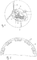
- a wind turbine according to Fig. 1 has a stationary tower 1, which is attached to a base and protrudes vertically upwards from the base.
- a pulpit 2 is mounted rotatably about a vertical central longitudinal axis of the tower 1.
- the pulpit 2 carries a rotor 3, which acts on an electrical generator inside the pulpit 2 via a gear.
- the pulpit 2 is rotated by an azimuth drive, not shown in detail.
- the pulpit 2 is aligned with the corresponding wind direction in such a way that the rotor 3 is always directed into the wind.
- the pulpit is assigned a horizontally aligned brake disk ring 4, which is non-rotatable with the pulpit 2.
- a large number of disc brakes 5 act on the brake disc ring 4 ( Fig. 2 ), which are arranged distributed over the circumference of the brake disk ring 4 and which are fixed to the tower 1 in a stationary manner.
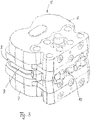
- Each disc brake 5 is hydraulically actuated and has according to the Figures 3 to 5 a brake housing, which is composed of two housing halves 6 and 7 is.
- the two housing halves 6 and 7 are mirror-symmetrical to a central horizontal plane, but are otherwise identical to one another. Both housing halves 6 and 7 have a rear housing area in which the housing halves 6 and 7 lie on top of one another and are firmly connected to one another via screw connections (not shown). Both housing halves 6 and 7 are also spaced apart from one another in a housing front area, forming a receiving mouth 8.
- the receiving mouth 8 forms a gap which extends over the entire width of the brake housing into the housing front area and is open on three sides, through which the brake disk ring 4 is passed.
- the two housing halves 6 and 7 consequently flank the brake disk ring 4 in the area of its upper side and in the area of its lower side in parallel.
- two brake pistons are mounted in a reciprocating manner, which act on a friction lining carrier 9 in the area of the receiving mouth 8, which is clamped in a corresponding receiving area of the respective housing half 6, 7.
- a friction lining carrier 9 When pressure is applied by an assigned brake piston, the respective friction lining carriers 9 are pressed against the corresponding surface of the brake disk ring.
- Each friction lining carrier 9 carries a friction lining in a manner not shown in detail.
- the two friction lining carriers 9 each of a housing half 6, 7 are acted upon in pairs by the respective pair of brake pistons.
- the opposing pairs of brake pistons in the two housing halves 6 and 7 can move in opposite directions, synchronously, so that the friction linings are pressed against the top and bottom of the brake disc ring 4 at the same time when the disc brake is acted upon accordingly.
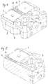
- the corresponding housing half 6, 7 has a central web 12 which separates the two receiving spaces for the two friction lining carriers 9 of the respective housing half 6, 7 from one another.
- the two housing halves 6, 7 rest against one another in their rear housing area.
- This rear housing area is provided with a cleaning channel 10 in the center and in alignment with the central web 12 of the front housing area, which is open both towards the front towards the receiving mouth 8 and towards the rear towards a rear side of the housing.
- the cleaning channel 10 is formed by an open channel section in each case in the respective housing half 6, 7, the open channel sections being designed mirror-symmetrically to the parting plane, but otherwise identical to one another.
- the closed cleaning channel 10, which has a rectangular free cross-section, is formed by the two housing halves 6 and 7 lying one on top of the other in the rear housing area.
- a cleaning groove 11 is also provided in each housing half 6, 7, which is aligned with the cleaning channel 10 and inclined towards a housing front side, ie away from the cleaning channel 10.
- the cleaning groove 11 in the area of the lower housing half 7 is designed to be continuously sloping towards the front of the housing, which results in the function of a slide.
- the complementary cleaning groove in the area of the upper housing half 6 rises relative to the horizontal parting plane towards the front of the housing, specifically mirror-symmetrically to the inclination of the cleaning groove 11 in the lower housing half 7.
- the cleaning groove 11 also widens towards the front of the housing on both sides in the manner of a funnel , whereby the free cross section of the cleaning groove 11 inevitably increases towards the front of the housing.
- the cleaning groove 11 is formed like a channel with a base and two side walls in the area of the central web 12.
- the base drops continuously towards the front of the housing, which inevitably means that the two side walls towards the front of the housing are always higher. This is because the central web 12 has an edge region which remains parallel to the horizontal parting plane.
- the corresponding cleaning brush is dimensioned such that it can be manually pushed through the cleaning channel 10 both above and below the brake disk ring to the respective central web 12 of the upper housing half 6 or the lower housing half 7 by a corresponding operator. This ensures that corresponding abrasion can be removed both in the area of the upper housing half 6 and in the area of the lower housing half 7.
- Both the cleaning channel 10 and the cleaning grooves 11 are formed in one piece in the two housing halves 6, 7 during the manufacture of the housing halves.
- the corresponding channel sections of the cleaning channel 10 and the cleaning grooves 11 are preferably already provided in a casting tool for producing the housing halves 6, 7, so that the channel sections for the cleaning channel 10 and the cleaning grooves 11 are introduced as cast metal parts directly after the completion of the housing halves 6 and 7 without additional machining.
Landscapes
- Engineering & Computer Science (AREA)
- General Engineering & Computer Science (AREA)
- Mechanical Engineering (AREA)
- Life Sciences & Earth Sciences (AREA)
- Sustainable Development (AREA)
- Sustainable Energy (AREA)
- Chemical & Material Sciences (AREA)
- Combustion & Propulsion (AREA)
- Braking Arrangements (AREA)
Applications Claiming Priority (2)
| Application Number | Priority Date | Filing Date | Title |
|---|---|---|---|
| DE102016213824.3A DE102016213824A1 (de) | 2016-07-27 | 2016-07-27 | Scheibenbremse für einen Bremsscheibenring eines Azimutantriebs einer Windkraftanlage |
| PCT/EP2017/067760 WO2018019606A1 (de) | 2016-07-27 | 2017-07-13 | Scheibenbremse für einen bremsscheibenring eines azimutantriebs einer windkraftanlage |
Publications (2)
| Publication Number | Publication Date |
|---|---|
| EP3491237A1 EP3491237A1 (de) | 2019-06-05 |
| EP3491237B1 true EP3491237B1 (de) | 2021-05-12 |
Family
ID=59325319
Family Applications (1)
| Application Number | Title | Priority Date | Filing Date |
|---|---|---|---|
| EP17739284.2A Active EP3491237B1 (de) | 2016-07-27 | 2017-07-13 | Scheibenbremse für einen bremsscheibenring eines azimutantriebs einer windkraftanlage |
Country Status (7)
| Country | Link |
|---|---|
| US (1) | US10823143B2 (da) |
| EP (1) | EP3491237B1 (da) |
| CN (1) | CN109790820B (da) |
| DE (1) | DE102016213824A1 (da) |
| DK (1) | DK3491237T3 (da) |
| ES (1) | ES2882009T3 (da) |
| WO (1) | WO2018019606A1 (da) |
Families Citing this family (6)
| Publication number | Priority date | Publication date | Assignee | Title |
|---|---|---|---|---|
| CN108443092B (zh) * | 2018-03-31 | 2023-10-27 | 长沙智纯机械设备有限公司 | 风力发电机组的偏航制动盘高空修复装置及其使用方法 |
| CN108607826A (zh) * | 2018-06-06 | 2018-10-02 | 华仪风能有限公司 | 风力发电机组偏航制动器摩擦片表面清理工装及其清理方法 |
| US10975732B2 (en) * | 2019-04-04 | 2021-04-13 | General Electric Company | Rotor turning device for balancing a wind turbine rotor |
| US11592003B2 (en) * | 2020-02-25 | 2023-02-28 | General Electric Company | Yaw braking assembly of a wind turbine |
| CN114060240B (zh) * | 2020-07-29 | 2023-05-09 | 新疆金风科技股份有限公司 | 偏航刹车盘的清扫装置及风力发电机组 |
| CN113236685B (zh) * | 2021-05-19 | 2023-04-07 | 宿迁学院 | 一种电子机械式制动器 |
Citations (1)
| Publication number | Priority date | Publication date | Assignee | Title |
|---|---|---|---|---|
| KR101464598B1 (ko) * | 2013-09-24 | 2014-11-25 | 상신브레이크주식회사 | 패드 가이드 장치를 구비한 풍력발전기용 요 브레이크 |
Family Cites Families (12)
| Publication number | Priority date | Publication date | Assignee | Title |
|---|---|---|---|---|
| JPH0313376Y2 (da) * | 1984-09-14 | 1991-03-27 | ||
| EP1016804B1 (en) * | 1998-12-31 | 2004-10-06 | Freni Brembo S.p.A. | Cooling device for motor vehicle disk brake |
| DE102008008437B4 (de) | 2008-02-09 | 2010-08-12 | Nordex Energy Gmbh | Azimutbremse für eine Windenergieanlage und Verfahren zum Betreiben einer Windenergieanlage mit einer Azimutbremse |
| DE102009049906A1 (de) * | 2009-10-12 | 2011-04-14 | Stromag Wep Gmbh | Scheibenbremse für einen Azimutantrieb einer Windkraftanlage |
| CA2716139A1 (en) * | 2010-10-01 | 2012-04-01 | Torx Friction Corporation | Noise-damping friction pads |
| CN102493917A (zh) * | 2011-12-28 | 2012-06-13 | 新疆金风科技股份有限公司 | 用于风力发电机的偏航系统的刹车盘 |
| DE102012202438B3 (de) | 2012-02-17 | 2013-03-28 | Stromag Wep Gmbh | Hydraulisch betätigbare Scheibenbremse und Azimutantrieb |
| ES2549531T3 (es) * | 2012-10-19 | 2015-10-29 | Nordex Energy Gmbh | Procedimiento y chapa de limpieza para la limpieza de un freno de una instalación de energía eólica |
| US20150337804A1 (en) * | 2013-05-24 | 2015-11-26 | S.B. Patent Holding Aps | Wind Turbine Provided With Yaw Brake |
| KR20150033805A (ko) * | 2013-09-24 | 2015-04-02 | 상신브레이크주식회사 | 미들바를 갖는 풍력발전기용 요 브레이크 시스템 |
| CN104074891B (zh) * | 2014-06-04 | 2016-08-17 | 焦作瑞塞尔盘式制动器有限公司 | 液压直动制动器 |
| DK3139058T3 (da) * | 2015-09-04 | 2018-04-23 | Sb Patent Holding Aps | Servicesystem og fremgangsmåde til service af en bremseindretning til et bremsesystem med en vandret placeret bremseskive |
-
2016
- 2016-07-27 DE DE102016213824.3A patent/DE102016213824A1/de not_active Ceased
-
2017
- 2017-07-13 DK DK17739284.2T patent/DK3491237T3/da active
- 2017-07-13 CN CN201780046196.XA patent/CN109790820B/zh active Active
- 2017-07-13 EP EP17739284.2A patent/EP3491237B1/de active Active
- 2017-07-13 WO PCT/EP2017/067760 patent/WO2018019606A1/de not_active Ceased
- 2017-07-13 ES ES17739284T patent/ES2882009T3/es active Active
- 2017-07-13 US US16/319,979 patent/US10823143B2/en not_active Expired - Fee Related
Patent Citations (1)
| Publication number | Priority date | Publication date | Assignee | Title |
|---|---|---|---|---|
| KR101464598B1 (ko) * | 2013-09-24 | 2014-11-25 | 상신브레이크주식회사 | 패드 가이드 장치를 구비한 풍력발전기용 요 브레이크 |
Also Published As
| Publication number | Publication date |
|---|---|
| WO2018019606A1 (de) | 2018-02-01 |
| CN109790820B (zh) | 2021-07-09 |
| US20190264654A1 (en) | 2019-08-29 |
| DK3491237T3 (da) | 2021-08-09 |
| DE102016213824A1 (de) | 2018-02-01 |
| EP3491237A1 (de) | 2019-06-05 |
| CN109790820A (zh) | 2019-05-21 |
| US10823143B2 (en) | 2020-11-03 |
| ES2882009T3 (es) | 2021-11-30 |
Similar Documents
| Publication | Publication Date | Title |
|---|---|---|
| EP3491237B1 (de) | Scheibenbremse für einen bremsscheibenring eines azimutantriebs einer windkraftanlage | |
| DE102010053879A1 (de) | Sammelvorrichtung für Bremsstaub | |
| EP1842620B1 (de) | Abdeckung für Maschinenführungen | |
| DE102016104969A1 (de) | Scheibenbremse für ein Nutzfahrzeug | |
| EP2488750B1 (de) | Scheibenbremse für einen azimutantrieb einer windkraftanlage | |
| DE68905025T2 (de) | Vorrichtung zum entfernen von spaenen fuer mehrspindlige werkzeugmaschine. | |
| WO2006045412A2 (de) | Extruder | |
| DE102013015873A1 (de) | Abstreifvorrichtung für eine Bodenfräsmaschine sowie Bodenfräsmaschine mit einer solchen Abstreifvorrichtung | |
| DE102013018093B3 (de) | Pressvorrichtung | |
| DE102005052434B4 (de) | Scheibenbremse, insbesondere für ein Nutzfahrzeug | |
| DE102008007193B4 (de) | Abstreifwalze für eine Textilmaschine | |
| DE102022000524A1 (de) | Einrichtung zum Aufhängen eines Vorhanges | |
| DE7829168U1 (de) | Scheibenbremse | |
| DE2342111C3 (de) | Verfahren und Vorrichtung zum Herstellen von Kanälen in Schaumstoff | |
| DE102019111343B4 (de) | Haltevorrichtung | |
| DE102006005235B4 (de) | Lamellenanordnung für Fassaden | |
| DE202010003071U1 (de) | Lamellenfenster | |
| DE102007029119A1 (de) | Schließeinheit einer Spritzgießmaschine | |
| DE102018127475B4 (de) | Bremsbelaghalterung für ein Schienenfahrzeug | |
| DE2429654C3 (de) | Haltevorrichtung für Düsenplatten in Strangpressen für thermoplastische Schmelzen | |
| WO2025082902A1 (de) | Filtratsammelkanal | |
| DE1965958B2 (de) | Beregnungseinrichtung | |
| DE102012106188A1 (de) | Werkzeuganordnung zum Herstellen von Wandschlitzen | |
| DE2158693C3 (de) | Druck- oder Saugventil, insbesondere für Kolbenverdichter | |
| DE19919690C2 (de) | Filterstufenrechen zum Sammeln und Abgeben von festen Bestandteilen aus strömenden Flüssigkeiten |
Legal Events
| Date | Code | Title | Description |
|---|---|---|---|
| STAA | Information on the status of an ep patent application or granted ep patent |
Free format text: STATUS: UNKNOWN |
|
| STAA | Information on the status of an ep patent application or granted ep patent |
Free format text: STATUS: THE INTERNATIONAL PUBLICATION HAS BEEN MADE |
|
| PUAI | Public reference made under article 153(3) epc to a published international application that has entered the european phase |
Free format text: ORIGINAL CODE: 0009012 |
|
| STAA | Information on the status of an ep patent application or granted ep patent |
Free format text: STATUS: REQUEST FOR EXAMINATION WAS MADE |
|
| 17P | Request for examination filed |
Effective date: 20190121 |
|
| AK | Designated contracting states |
Kind code of ref document: A1 Designated state(s): AL AT BE BG CH CY CZ DE DK EE ES FI FR GB GR HR HU IE IS IT LI LT LU LV MC MK MT NL NO PL PT RO RS SE SI SK SM TR |
|
| AX | Request for extension of the european patent |
Extension state: BA ME |
|
| DAV | Request for validation of the european patent (deleted) | ||
| DAX | Request for extension of the european patent (deleted) | ||
| STAA | Information on the status of an ep patent application or granted ep patent |
Free format text: STATUS: EXAMINATION IS IN PROGRESS |
|
| 17Q | First examination report despatched |
Effective date: 20200228 |
|
| GRAP | Despatch of communication of intention to grant a patent |
Free format text: ORIGINAL CODE: EPIDOSNIGR1 |
|
| STAA | Information on the status of an ep patent application or granted ep patent |
Free format text: STATUS: GRANT OF PATENT IS INTENDED |
|
| RIC1 | Information provided on ipc code assigned before grant |
Ipc: F03D 7/02 20060101AFI20201127BHEP Ipc: F16D 121/04 20120101ALI20201127BHEP Ipc: F03D 80/55 20160101ALI20201127BHEP Ipc: F16D 55/225 20060101ALI20201127BHEP Ipc: F16D 65/00 20060101ALI20201127BHEP |
|
| INTG | Intention to grant announced |
Effective date: 20201218 |
|
| GRAS | Grant fee paid |
Free format text: ORIGINAL CODE: EPIDOSNIGR3 |
|
| GRAA | (expected) grant |
Free format text: ORIGINAL CODE: 0009210 |
|
| STAA | Information on the status of an ep patent application or granted ep patent |
Free format text: STATUS: THE PATENT HAS BEEN GRANTED |
|
| AK | Designated contracting states |
Kind code of ref document: B1 Designated state(s): AL AT BE BG CH CY CZ DE DK EE ES FI FR GB GR HR HU IE IS IT LI LT LU LV MC MK MT NL NO PL PT RO RS SE SI SK SM TR |
|
| REG | Reference to a national code |
Ref country code: GB Ref legal event code: FG4D Free format text: NOT ENGLISH |
|
| REG | Reference to a national code |
Ref country code: CH Ref legal event code: EP |
|
| REG | Reference to a national code |
Ref country code: DE Ref legal event code: R096 Ref document number: 502017010351 Country of ref document: DE |
|
| REG | Reference to a national code |
Ref country code: IE Ref legal event code: FG4D Free format text: LANGUAGE OF EP DOCUMENT: GERMAN |
|
| REG | Reference to a national code |
Ref country code: AT Ref legal event code: REF Ref document number: 1392343 Country of ref document: AT Kind code of ref document: T Effective date: 20210615 |
|
| REG | Reference to a national code |
Ref country code: DK Ref legal event code: T3 Effective date: 20210804 |
|
| REG | Reference to a national code |
Ref country code: SE Ref legal event code: TRGR |
|
| REG | Reference to a national code |
Ref country code: LT Ref legal event code: MG9D |
|
| REG | Reference to a national code |
Ref country code: NL Ref legal event code: MP Effective date: 20210512 |
|
| PG25 | Lapsed in a contracting state [announced via postgrant information from national office to epo] |
Ref country code: FI Free format text: LAPSE BECAUSE OF FAILURE TO SUBMIT A TRANSLATION OF THE DESCRIPTION OR TO PAY THE FEE WITHIN THE PRESCRIBED TIME-LIMIT Effective date: 20210512 Ref country code: LT Free format text: LAPSE BECAUSE OF FAILURE TO SUBMIT A TRANSLATION OF THE DESCRIPTION OR TO PAY THE FEE WITHIN THE PRESCRIBED TIME-LIMIT Effective date: 20210512 Ref country code: BG Free format text: LAPSE BECAUSE OF FAILURE TO SUBMIT A TRANSLATION OF THE DESCRIPTION OR TO PAY THE FEE WITHIN THE PRESCRIBED TIME-LIMIT Effective date: 20210812 Ref country code: HR Free format text: LAPSE BECAUSE OF FAILURE TO SUBMIT A TRANSLATION OF THE DESCRIPTION OR TO PAY THE FEE WITHIN THE PRESCRIBED TIME-LIMIT Effective date: 20210512 |
|
| PG25 | Lapsed in a contracting state [announced via postgrant information from national office to epo] |
Ref country code: LV Free format text: LAPSE BECAUSE OF FAILURE TO SUBMIT A TRANSLATION OF THE DESCRIPTION OR TO PAY THE FEE WITHIN THE PRESCRIBED TIME-LIMIT Effective date: 20210512 Ref country code: IS Free format text: LAPSE BECAUSE OF FAILURE TO SUBMIT A TRANSLATION OF THE DESCRIPTION OR TO PAY THE FEE WITHIN THE PRESCRIBED TIME-LIMIT Effective date: 20210912 Ref country code: GR Free format text: LAPSE BECAUSE OF FAILURE TO SUBMIT A TRANSLATION OF THE DESCRIPTION OR TO PAY THE FEE WITHIN THE PRESCRIBED TIME-LIMIT Effective date: 20210813 Ref country code: RS Free format text: LAPSE BECAUSE OF FAILURE TO SUBMIT A TRANSLATION OF THE DESCRIPTION OR TO PAY THE FEE WITHIN THE PRESCRIBED TIME-LIMIT Effective date: 20210512 Ref country code: NO Free format text: LAPSE BECAUSE OF FAILURE TO SUBMIT A TRANSLATION OF THE DESCRIPTION OR TO PAY THE FEE WITHIN THE PRESCRIBED TIME-LIMIT Effective date: 20210812 Ref country code: PT Free format text: LAPSE BECAUSE OF FAILURE TO SUBMIT A TRANSLATION OF THE DESCRIPTION OR TO PAY THE FEE WITHIN THE PRESCRIBED TIME-LIMIT Effective date: 20210913 Ref country code: PL Free format text: LAPSE BECAUSE OF FAILURE TO SUBMIT A TRANSLATION OF THE DESCRIPTION OR TO PAY THE FEE WITHIN THE PRESCRIBED TIME-LIMIT Effective date: 20210512 |
|
| REG | Reference to a national code |
Ref country code: ES Ref legal event code: FG2A Ref document number: 2882009 Country of ref document: ES Kind code of ref document: T3 Effective date: 20211130 |
|
| PG25 | Lapsed in a contracting state [announced via postgrant information from national office to epo] |
Ref country code: NL Free format text: LAPSE BECAUSE OF FAILURE TO SUBMIT A TRANSLATION OF THE DESCRIPTION OR TO PAY THE FEE WITHIN THE PRESCRIBED TIME-LIMIT Effective date: 20210512 |
|
| PG25 | Lapsed in a contracting state [announced via postgrant information from national office to epo] |
Ref country code: RO Free format text: LAPSE BECAUSE OF FAILURE TO SUBMIT A TRANSLATION OF THE DESCRIPTION OR TO PAY THE FEE WITHIN THE PRESCRIBED TIME-LIMIT Effective date: 20210512 Ref country code: CZ Free format text: LAPSE BECAUSE OF FAILURE TO SUBMIT A TRANSLATION OF THE DESCRIPTION OR TO PAY THE FEE WITHIN THE PRESCRIBED TIME-LIMIT Effective date: 20210512 Ref country code: EE Free format text: LAPSE BECAUSE OF FAILURE TO SUBMIT A TRANSLATION OF THE DESCRIPTION OR TO PAY THE FEE WITHIN THE PRESCRIBED TIME-LIMIT Effective date: 20210512 Ref country code: SK Free format text: LAPSE BECAUSE OF FAILURE TO SUBMIT A TRANSLATION OF THE DESCRIPTION OR TO PAY THE FEE WITHIN THE PRESCRIBED TIME-LIMIT Effective date: 20210512 Ref country code: SM Free format text: LAPSE BECAUSE OF FAILURE TO SUBMIT A TRANSLATION OF THE DESCRIPTION OR TO PAY THE FEE WITHIN THE PRESCRIBED TIME-LIMIT Effective date: 20210512 |
|
| REG | Reference to a national code |
Ref country code: DE Ref legal event code: R097 Ref document number: 502017010351 Country of ref document: DE |
|
| REG | Reference to a national code |
Ref country code: CH Ref legal event code: PL |
|
| PLBE | No opposition filed within time limit |
Free format text: ORIGINAL CODE: 0009261 |
|
| STAA | Information on the status of an ep patent application or granted ep patent |
Free format text: STATUS: NO OPPOSITION FILED WITHIN TIME LIMIT |
|
| PG25 | Lapsed in a contracting state [announced via postgrant information from national office to epo] |
Ref country code: MC Free format text: LAPSE BECAUSE OF FAILURE TO SUBMIT A TRANSLATION OF THE DESCRIPTION OR TO PAY THE FEE WITHIN THE PRESCRIBED TIME-LIMIT Effective date: 20210512 |
|
| REG | Reference to a national code |
Ref country code: BE Ref legal event code: MM Effective date: 20210731 |
|
| 26N | No opposition filed |
Effective date: 20220215 |
|
| PG25 | Lapsed in a contracting state [announced via postgrant information from national office to epo] |
Ref country code: LI Free format text: LAPSE BECAUSE OF NON-PAYMENT OF DUE FEES Effective date: 20210731 Ref country code: CH Free format text: LAPSE BECAUSE OF NON-PAYMENT OF DUE FEES Effective date: 20210731 |
|
| PG25 | Lapsed in a contracting state [announced via postgrant information from national office to epo] |
Ref country code: IS Free format text: LAPSE BECAUSE OF FAILURE TO SUBMIT A TRANSLATION OF THE DESCRIPTION OR TO PAY THE FEE WITHIN THE PRESCRIBED TIME-LIMIT Effective date: 20210912 Ref country code: LU Free format text: LAPSE BECAUSE OF NON-PAYMENT OF DUE FEES Effective date: 20210713 Ref country code: FR Free format text: LAPSE BECAUSE OF NON-PAYMENT OF DUE FEES Effective date: 20210731 Ref country code: AL Free format text: LAPSE BECAUSE OF FAILURE TO SUBMIT A TRANSLATION OF THE DESCRIPTION OR TO PAY THE FEE WITHIN THE PRESCRIBED TIME-LIMIT Effective date: 20210512 |
|
| PG25 | Lapsed in a contracting state [announced via postgrant information from national office to epo] |
Ref country code: IT Free format text: LAPSE BECAUSE OF FAILURE TO SUBMIT A TRANSLATION OF THE DESCRIPTION OR TO PAY THE FEE WITHIN THE PRESCRIBED TIME-LIMIT Effective date: 20210512 Ref country code: BE Free format text: LAPSE BECAUSE OF NON-PAYMENT OF DUE FEES Effective date: 20210731 |
|
| P01 | Opt-out of the competence of the unified patent court (upc) registered |
Effective date: 20230504 |
|
| PG25 | Lapsed in a contracting state [announced via postgrant information from national office to epo] |
Ref country code: CY Free format text: LAPSE BECAUSE OF FAILURE TO SUBMIT A TRANSLATION OF THE DESCRIPTION OR TO PAY THE FEE WITHIN THE PRESCRIBED TIME-LIMIT Effective date: 20210512 |
|
| PG25 | Lapsed in a contracting state [announced via postgrant information from national office to epo] |
Ref country code: HU Free format text: LAPSE BECAUSE OF FAILURE TO SUBMIT A TRANSLATION OF THE DESCRIPTION OR TO PAY THE FEE WITHIN THE PRESCRIBED TIME-LIMIT; INVALID AB INITIO Effective date: 20170713 |
|
| REG | Reference to a national code |
Ref country code: AT Ref legal event code: MM01 Ref document number: 1392343 Country of ref document: AT Kind code of ref document: T Effective date: 20220713 |
|
| PG25 | Lapsed in a contracting state [announced via postgrant information from national office to epo] |
Ref country code: AT Free format text: LAPSE BECAUSE OF NON-PAYMENT OF DUE FEES Effective date: 20220713 |
|
| PG25 | Lapsed in a contracting state [announced via postgrant information from national office to epo] |
Ref country code: MK Free format text: LAPSE BECAUSE OF FAILURE TO SUBMIT A TRANSLATION OF THE DESCRIPTION OR TO PAY THE FEE WITHIN THE PRESCRIBED TIME-LIMIT Effective date: 20210512 |
|
| PG25 | Lapsed in a contracting state [announced via postgrant information from national office to epo] |
Ref country code: MT Free format text: LAPSE BECAUSE OF FAILURE TO SUBMIT A TRANSLATION OF THE DESCRIPTION OR TO PAY THE FEE WITHIN THE PRESCRIBED TIME-LIMIT Effective date: 20210512 |
|
| PGFP | Annual fee paid to national office [announced via postgrant information from national office to epo] |
Ref country code: ES Payment date: 20250801 Year of fee payment: 9 |
|
| PGFP | Annual fee paid to national office [announced via postgrant information from national office to epo] |
Ref country code: DK Payment date: 20250725 Year of fee payment: 9 Ref country code: DE Payment date: 20250729 Year of fee payment: 9 |
|
| PGFP | Annual fee paid to national office [announced via postgrant information from national office to epo] |
Ref country code: TR Payment date: 20250709 Year of fee payment: 9 |
|
| PGFP | Annual fee paid to national office [announced via postgrant information from national office to epo] |
Ref country code: GB Payment date: 20250728 Year of fee payment: 9 |
|
| PGFP | Annual fee paid to national office [announced via postgrant information from national office to epo] |
Ref country code: SE Payment date: 20250727 Year of fee payment: 9 |
|
| PGFP | Annual fee paid to national office [announced via postgrant information from national office to epo] |
Ref country code: IE Payment date: 20250728 Year of fee payment: 9 |