EP3489757A2 - Entwicklungsvorrichtung - Google Patents
Entwicklungsvorrichtung Download PDFInfo
- Publication number
- EP3489757A2 EP3489757A2 EP18205335.5A EP18205335A EP3489757A2 EP 3489757 A2 EP3489757 A2 EP 3489757A2 EP 18205335 A EP18205335 A EP 18205335A EP 3489757 A2 EP3489757 A2 EP 3489757A2
- Authority
- EP
- European Patent Office
- Prior art keywords
- developing device
- regulating blade
- blade
- developer carrying
- carrying member
- Prior art date
- Legal status (The legal status is an assumption and is not a legal conclusion. Google has not performed a legal analysis and makes no representation as to the accuracy of the status listed.)
- Withdrawn
Links
- 230000001105 regulatory effect Effects 0.000 claims abstract description 240
- 239000000853 adhesive Substances 0.000 claims description 153
- 230000001070 adhesive effect Effects 0.000 claims description 153
- 239000011347 resin Substances 0.000 claims description 132
- 229920005989 resin Polymers 0.000 claims description 132
- 239000000463 material Substances 0.000 claims description 114
- 238000012546 transfer Methods 0.000 description 59
- 239000011248 coating agent Substances 0.000 description 47
- 238000000576 coating method Methods 0.000 description 47
- 230000008859 change Effects 0.000 description 18
- 230000003247 decreasing effect Effects 0.000 description 16
- 238000000034 method Methods 0.000 description 12
- 238000003756 stirring Methods 0.000 description 10
- 230000001965 increasing effect Effects 0.000 description 9
- 239000000470 constituent Substances 0.000 description 8
- 239000002184 metal Substances 0.000 description 7
- 229910052751 metal Inorganic materials 0.000 description 7
- 238000000465 moulding Methods 0.000 description 7
- 238000012937 correction Methods 0.000 description 6
- 230000008569 process Effects 0.000 description 6
- 239000003086 colorant Substances 0.000 description 5
- 238000011144 upstream manufacturing Methods 0.000 description 5
- 238000004026 adhesive bonding Methods 0.000 description 4
- 230000015572 biosynthetic process Effects 0.000 description 4
- 230000008021 deposition Effects 0.000 description 4
- 238000004519 manufacturing process Methods 0.000 description 4
- 238000005192 partition Methods 0.000 description 4
- 230000006641 stabilisation Effects 0.000 description 4
- 238000011105 stabilization Methods 0.000 description 4
- 230000008602 contraction Effects 0.000 description 3
- 238000007599 discharging Methods 0.000 description 3
- 238000003466 welding Methods 0.000 description 3
- 238000004140 cleaning Methods 0.000 description 2
- 238000006073 displacement reaction Methods 0.000 description 2
- 230000002708 enhancing effect Effects 0.000 description 2
- 238000005259 measurement Methods 0.000 description 2
- 238000012986 modification Methods 0.000 description 2
- 230000004048 modification Effects 0.000 description 2
- 230000000087 stabilizing effect Effects 0.000 description 2
- 238000005520 cutting process Methods 0.000 description 1
- 230000001934 delay Effects 0.000 description 1
- 230000000694 effects Effects 0.000 description 1
- 230000004907 flux Effects 0.000 description 1
- 238000001746 injection moulding Methods 0.000 description 1
- 239000007769 metal material Substances 0.000 description 1
- 230000002093 peripheral effect Effects 0.000 description 1
- 238000003825 pressing Methods 0.000 description 1
- 230000001846 repelling effect Effects 0.000 description 1
- 238000000926 separation method Methods 0.000 description 1
Images


Classifications
-
- G—PHYSICS
- G03—PHOTOGRAPHY; CINEMATOGRAPHY; ANALOGOUS TECHNIQUES USING WAVES OTHER THAN OPTICAL WAVES; ELECTROGRAPHY; HOLOGRAPHY
- G03G—ELECTROGRAPHY; ELECTROPHOTOGRAPHY; MAGNETOGRAPHY
- G03G15/00—Apparatus for electrographic processes using a charge pattern
- G03G15/06—Apparatus for electrographic processes using a charge pattern for developing
- G03G15/08—Apparatus for electrographic processes using a charge pattern for developing using a solid developer, e.g. powder developer
- G03G15/0806—Apparatus for electrographic processes using a charge pattern for developing using a solid developer, e.g. powder developer on a donor element, e.g. belt, roller
- G03G15/0812—Apparatus for electrographic processes using a charge pattern for developing using a solid developer, e.g. powder developer on a donor element, e.g. belt, roller characterised by the developer regulating means, e.g. structure of doctor blade
-
- G—PHYSICS
- G03—PHOTOGRAPHY; CINEMATOGRAPHY; ANALOGOUS TECHNIQUES USING WAVES OTHER THAN OPTICAL WAVES; ELECTROGRAPHY; HOLOGRAPHY
- G03G—ELECTROGRAPHY; ELECTROPHOTOGRAPHY; MAGNETOGRAPHY
- G03G15/00—Apparatus for electrographic processes using a charge pattern
- G03G15/06—Apparatus for electrographic processes using a charge pattern for developing
- G03G15/08—Apparatus for electrographic processes using a charge pattern for developing using a solid developer, e.g. powder developer
- G03G15/0806—Apparatus for electrographic processes using a charge pattern for developing using a solid developer, e.g. powder developer on a donor element, e.g. belt, roller
- G03G15/081—Apparatus for electrographic processes using a charge pattern for developing using a solid developer, e.g. powder developer on a donor element, e.g. belt, roller characterised by the developer handling means after the supply and before the regulating, e.g. means for preventing developer blocking
-
- G—PHYSICS
- G03—PHOTOGRAPHY; CINEMATOGRAPHY; ANALOGOUS TECHNIQUES USING WAVES OTHER THAN OPTICAL WAVES; ELECTROGRAPHY; HOLOGRAPHY
- G03G—ELECTROGRAPHY; ELECTROPHOTOGRAPHY; MAGNETOGRAPHY
- G03G2215/00—Apparatus for electrophotographic processes
- G03G2215/06—Developing structures, details
- G03G2215/0634—Developing device
-
- G—PHYSICS
- G03—PHOTOGRAPHY; CINEMATOGRAPHY; ANALOGOUS TECHNIQUES USING WAVES OTHER THAN OPTICAL WAVES; ELECTROGRAPHY; HOLOGRAPHY
- G03G—ELECTROGRAPHY; ELECTROPHOTOGRAPHY; MAGNETOGRAPHY
- G03G2221/00—Processes not provided for by group G03G2215/00, e.g. cleaning or residual charge elimination
- G03G2221/16—Mechanical means for facilitating the maintenance of the apparatus, e.g. modular arrangements and complete machine concepts
- G03G2221/1651—Mechanical means for facilitating the maintenance of the apparatus, e.g. modular arrangements and complete machine concepts for connecting the different parts
- G03G2221/1654—Locks and means for positioning or alignment
Definitions
- the present invention relates to a developing device including a resin-made regulating blade.
- the developing device includes a developing device frame, a rotatable developer carrying member for carrying a developer in order to develop an electrostatic latent image formed on an image bearing member, and a regulating blade as a developer regulating member for regulating an amount of the developer carried on the developer carrying member.
- the regulating blade is provided opposed to the developer carrying member with a predetermined gap between itself and the developer carrying member over a direction parallel to a rotational axis of the developer carrying member (hereinafter, the gap is referred to as an SB gap).
- the SB gap refers to a minimum distance between the developer carrying member and the regulating blade.
- the resin-made regulating blade is mounted and fixed to a blade mounting portion of the resin-made developing device frame.
- a longitudinal length of the regulating blade in a region (maximum image region of the regulating blade) corresponding to a maximum image region of an image region in which the image is formable on the image bearing member increases.
- a longitudinal length of a surface of the blade mounting portion of the developing device frame on which the regulating blade is mounted (hereinafter, this surface is referred to as a blade mounting surface) increases.
- a magnitude of an SB gap in a state that the regulating blade is mounted on the blade mounting portion of the developing device frame having large flatness has a tendency that the magnitude of the SB gap is liable to be different with respect to a longitudinal direction of the developer carrying member.
- the magnitude of the SB gap is different with respect to the longitudinal direction of the developer carrying member, there is a liability that an amount of a developer carried on a surface of the developer carrying member causes unevenness with respect to the longitudinal direction of the developer carrying member.
- the resin-made developing device frame having the large longitudinal length of the blade mounting surface thereof is manufactured with accuracy of a general-purpose resin molded product, in order to make the flatness of the blade mounting surface of the developing device frame small, it would be considered that a length of the blade mounting surface of the developing device frame with respect to a widthwise direction of the developing device frame is made a predetermined value or less. Therefore, in the case where the resin-made regulating blade is fixed to the resin-made developing device frame having the length, of the blade mounting surface of the developing device frame with respect to the widthwise direction, which is the predetermined value or less, it is required that an attitude of the regulating blade mounted on the blade mounting surface of the developing device frame when the regulating blade is fixed to the developing device frame is stabilized.
- a first invention has been accomplished in view of the above-described problem.
- a principal object of the first invention is to provide a developing device capable of stabilizing an attitude of a regulating blade mounted on a blade mounting surface of a developing device frame when the regulating blade made of a resin material is fixed to the developing device frame made of a resin material while decreasing flatness of the blade mounting surface of the developing device frame made of the resin material, by a simple constitution.
- a degree of unevenness of a surface of the regulating blade to be mounted on the developing device frame (hereinafter, this surface is referred to as a surface-to-be-mounted) is liable to increase, so that there is a tendency that flatness (JIS B0021) of the surface-to-be-mounted of the regulating blade becomes large.
- a second invention has been accomplished in view of the above-described problem.
- a principal object of the second invention is to provide a developing device capable of stabilizing an attitude of a regulating blade mounted at a surface-to-be-mounted of the regulating blade on a developing device frame when the regulating blade made of a resin material is fixed to the developing device frame made of a resin material while decreasing flatness of the surface-to-be-mounted of the regulating blade made of the resin material, by a simple constitution.
- the adhesive having a predetermined film thickness is applied onto, for example, a blade mounting surface of the developing device frame. Then, when the regulating blade is mounted on the blade mounting portion of the developing device frame, in order to cause the regulating blade to be adhesively bonded to the blade mounting portion of the developing device frame, predetermined pressure is exerted on the regulating blade.
- the adhesive having the predetermined film thickness is deformed, so that there is a liability that the adhesive (excessive adhesive) escaping to an outside of a surface on which the adhesive is applied enters an inside of the developing device frame.
- this excessive adhesive is especially deposited on a guiding portion (developer guiding portion) for guiding the developer so as to be fed toward the SB gap and then is cured, there is a liability that a flow of the developer fed toward the SB gap fluctuates.
- a third invention has been accomplished in view of the above-described problem.
- a principal object of the third invention is to provide a developing device capable of suppressing entrance of the adhesive into the developing device frame when the regulating blade made of a resin material is mounted on the blade mounting portion in a constitution in which the regulating blade is mounted on the blade mounting portion of the developing device frame made of the resin material and then is fixed with the adhesive.
- a principal object of the first invention is to stabilize an attitude of a regulating blade mounted on a blade mounting surface of a developing device frame when the regulating blade made of a resin material is fixed to the developing device frame made of a resin material while decreasing flatness of the blade mounting surface of the developing device frame made of the resin material, by a simple constitution.
- a developing device comprising: a rotatable developer carrying member configured to carry a developer comprising toner and a carrier for developing an electrostatic latent image formed on an image bearing member; a regulating blade made of a resin material and provided opposed to the rotatable developer carrying member in non-contact with the rotatable developer carrying member, the regulating blade being configured to regulate an amount of the developer carried on the rotatable developer carrying member; and a developing device frame provided separately from the regulating blade and including a mounting portion configured to mount the regulating blade, wherein the developing device frame includes a first rib and a second rib which project from the mounting portion and which support the regulating blade, the first rib and the second rib extending along a rotational axis direction of the developer carrying member over a substantially entire region of the mounting portion corresponding to a maximum image region of the image bearing member in which an image is capable of forming, wherein when the developing device is seen in a cross section perpendicular to a
- a principal object of the second invention is to stabilize an attitude of a regulating blade mounted at a surface-to-be-mounted of the regulating blade on a developing device frame when the regulating blade made of a resin material is fixed to the developing device frame made of a resin material while decreasing flatness of the surface-to-be-mounted of the regulating blade made of the resin material, by a simple constitution.
- a developing device comprising: a rotatable developer carrying member configured to carry a developer comprising toner and a carrier for developing an electrostatic latent image formed on an image bearing member; a regulating blade made of a resin material and provided opposed to the rotatable developer carrying member in non-contact with the rotatable developer carrying member, the regulating blade being configured to regulate an amount of the developer carried on the rotatable developer carrying member and including a base portion and a regulating portion which is provided at a position thereof closest to the regulating blade and which is configured to regulate the amount of the developer carried on the rotatable developer carrying member; and a developing device frame provided separately from the regulating blade and including a mounting portion configured to mount the regulating blade, wherein the regulating blade includes a first rib and a second rib which project from the base portion and which are supported by the mounting portion, the first rib and the second rib extending along a rotational axis direction of the developer carrying member over a substantially entire
- a principal object of the third invention is to suppress entrance of the adhesive into the developing device frame when the regulating blade made of a resin material is mounted on the blade mounting portion in a constitution in which the regulating blade is mounted on the blade mounting portion of the developing device frame made of the resin material and then is fixed with the adhesive.
- a developing device comprising: a rotatable developer carrying member configured to carry a developer comprising toner and a carrier for developing an electrostatic latent image formed on an image bearing member; a regulating blade made of a resin material and provided opposed to the rotatable developer carrying member in non-contact with the rotatable developer carrying member, the regulating blade being configured to regulate an amount of the developer carried on the rotatable developer carrying member; and a developing device frame provided separately from the regulating blade and including a mounting portion configured to mount the regulating blade, wherein the regulating blade is fixed to the mounting portion with an adhesive in a region thereof corresponding to a maximum image region of the image bearing member in which an image is capable of forming, wherein when the developing device is seen in the cross section perpendicular to the rotational axis of the developer carrying member, a predetermined space for storing the adhesive is formed between the mounting portion and the regulating blade, and wherein the predetermined space is formed in a region of the mounting
- a developing device comprising: a rotatable developer carrying member configured to carry a developer comprising toner and a carrier for developing an electrostatic latent image formed on an image bearing member; a regulating blade made of a resin material and provided opposed to the rotatable developer carrying member in non-contact with the rotatable developer carrying member, the regulating blade being configured to regulate an amount of the developer carried on the rotatable developer carrying member; and a developing device frame provided separately from the regulating blade and including a mounting portion configured to mount the regulating blade, wherein the regulating blade is fixed to the mounting portion with an adhesive in a region thereof corresponding to a maximum image region of the image bearing member in which an image is capable of forming, wherein when the developing device is seen in the cross section perpendicular to the rotational axis of the developer carrying member, a predetermined space for storing the adhesive is formed between the mounting portion and the regulating blade, and wherein the predetermined space is formed in a region of
- an image forming apparatus 60 includes an endless intermediary transfer belt (ITB) 61 as an intermediary transfer member and four image forming portions 600 provided from an upstream side toward a downstream side along a rotational direction (arrow C direction of Figure 1 ) of the intermediary transfer belt 61.
- the image forming portions 600 form toner images of colors of yellow (Y), magenta (M), cyan (C) and black (Bk), respectively.
- the image forming portion 600 includes a rotatable photosensitive drum 1 as an image bearing member. Further, the image forming portion 600 includes a charging roller 2 as a charging means, a developing device 3 as a developing means, a primary transfer roller 4 as a primary transfer means and a photosensitive member cleaner 5 as a photosensitive member cleaning means, which are provided along a rotational direction of the photosensitive drum 1.
- Each of the developing devices 3 is detachably mountable to the image forming apparatus 60.
- Each of the developing devices 3 includes a developing container 50 which accommodates a two-component developer (hereinafter, simply referred to as a developer) containing non-magnetic toner (hereinafter, simply referred to as toner) and a magnetic carrier.
- a developer a two-component developer
- toner non-magnetic toner
- each of toner cartridges in which toners of the colors of Y, M, C and Bk is detachably mountable to the image forming apparatus 60.
- the toners of the respective colors of Y, M, C and Bk pass through toner feeding paths and are supplied to the developing containers 50, respectively.
- the intermediary transfer belt 61 is stretched by a tension roller 6, a follower roller 7a, the primary transfer roller 4, a follower roller 7b and an inner secondary transfer roller 66, and is fed and driven in the arrow C direction of Figure 1 .
- the inner secondary transfer roller 66 also functions as a driving roller for driving the intermediary transfer belt 61. With rotation of the inner secondary transfer roller 66, the intermediary transfer belt 61 is rotated in the arrow C direction of Figure 1 .
- the intermediary transfer belt 61 is pressed from a back-surface side of the intermediary transfer belt 61 by the primary transfer rollers 4. Further, the intermediary transfer belt 61 is contacted to the photosensitive drums 1, so that a primary transfer nip as a primary transfer portion is formed between each of the photosensitive drums 1 and the intermediary transfer belt 61.
- an intermediary transfer member cleaner 8 as a belt cleaning means is contacted to the intermediary transfer belt 61.
- an outer secondary transfer roller 67 as a secondary transfer means is provided at a position opposing the inner secondary transfer roller 66 through the intermediary transfer belt 61.
- the intermediary transfer belt 61 is sandwiched between the inner secondary transfer roller 66 and the outer secondary transfer roller 67.
- a secondary transfer nip as a secondary transfer portion is formed between the outer secondary transfer roller 67 and the intermediary transfer belt 61.
- the toner image is attracted to a surface of a sheet S (for example, paper, a film or the like) by applying a predetermined pressing force (pressure) and a transfer bias (electrostatic load bias).
- the sheets S are accommodated in a stacked state in a sheet accommodating portion 62 (for example, a feeding cassette, a feeding deck or the like).
- a feeding means 63 feeds the sheet S in synchronism with image forming timing by using, for example, a friction separation type or the like with a feeding roller or the like.
- the sheet S fed by the feeding means 63 is fed to a registration roller pair 65 provided at an intermediary position of a feeding path 64. After oblique movement correction and timing correction are carried out by the registration roller pair 65, the sheet S is fed to the secondary transfer nip. In the secondary transfer nip, timing when the sheet S reaches the secondary transfer nip and timing when the toner image reaches the secondary transfer nip coincide with each other, and thus secondary transfer is carried out.
- a fixing device 9 Downstream of the secondary transfer nip with respect to a feeding direction of the sheet S, a fixing device 9 is provided. To the sheet S fed to the fixing device 9, predetermined pressure and predetermined heat quantity are applied from the fixing device 9, so that the toner image is melt-fixed on a surface of the sheet S.
- the sheet S on which the image is fixed in the above-described manner is discharged onto a discharge tray 601 as it is by normal rotation of a discharging roller pair 69.
- the discharging roller pair 69 is reversely rotated. As a result, leading and trailing ends of the sheet S are replaced with each other, and the sheet S is fed to a feeding path 603 for the double-side image formation. Thereafter, the sheet S is fed to the feeding path 64 by a re-feeding roller pair 604 in synchronism with subsequent image forming timing.
- the photosensitive drum 1 is rotationally driven by a motor.
- the charging roller 2 charges the surface of the rotationally driven photosensitive drum 1 uniformly in advance.
- An exposure device 68 forms an electrostatic latent image on the surface of the photosensitive drum 1 charged by the charging roller 2, on the basis of a signal of image information inputted to the image forming apparatus 60.
- the photosensitive drum 1 is capable of permitting formation of electrostatic latent images of a plurality of sizes.
- the developing device 3 includes a rotatable developing sleeve 70 as a developer carrying member for carrying the developer.
- the developing device 3 develops the electrostatic latent image, formed on the surface of the photosensitive drum 1, with the developer carried on the surface of the developing sleeve 70.
- the toner is deposited on an exposed portion on the surface of the photosensitive drum 1, so that the electrostatic latent image is visualized as a visible image (toner image).
- a transfer bias electrostatic load bias
- Toner (transfer residual toner) remaining in a slight amount on the surface of the photosensitive drum 1 after the primary transfer is collected by the photosensitive member cleaner 5, and prepares for a subsequent image forming process.
- the image forming processes, for the respective colors, which are performed in parallel by the image forming portions 600 for the respective colors of Y, M, C and Bk are carried out at timings when an associated toner image is successively transferred superposedly onto the toner image for the color on an upstream image forming portion side.
- a full-color toner image is formed on the intermediary transfer belt 61, so that the toner image is fed to the secondary transfer nip.
- a transfer bias is applied, so that the toner image formed on the intermediary transfer belt 61 is transferred onto the sheet S fed to the secondary transfer nip.
- the fixing device 9 fixes the toner image transferred on the sheet.
- the sheet (recording material) S on which the toner image is fixed is discharged onto a discharge tray 601.
- a series of image forming processes as described above is ended and then the image forming apparatus 60 prepares for a subsequent image forming operation.
- Figure 4 is the sectional view of the developing device 3 at a cross-section H of Figure 2 .
- the developing device 3 includes a resin-made developing device frame 30 molded with a resin material and the developing container 50 which is formed separately from the developing device frame 30 and which is constituted by a resin-made cover frame 40 molded with a resin material.
- Figure 2 and Figure 4 show a state in which the cover frame 40 is mounted on the developing device frame 30, and Figure 3 shows a state in which the cover frame 40 is not mounted on the developing device frame 30.
- details of the developing device frame 30 (alone) will be described later with reference to Figure 6 .
- the developing container 50 is provided with an opening at a position corresponding to the developing region where the developing sleeve 70 opposes the photosensitive drum 1.
- the developing sleeve 70 is disposed rotatably relative to the developing container 50 so that a part of the developing sleeve 70 exposes.
- a bearing 71 as a bearing member is provided.
- An inside of the developing container 50 is partitioned (sectioned) into a developing chamber 31 as a first chamber and a stirring chamber 32 as a second chamber by a partition wall 38 extending in a vertical direction.
- the developing chamber 31 and the stirring chamber 32 are connected with each other at longitudinal end portions through two communicating portions 39 provided in the partition wall 38. For that reason, between the developing chamber 31 and the stirring chamber 32, the developer can move through the communicating portions 39.
- the developing chamber 31 and the stirring chamber 32 are arranged with respect to a horizontal direction.
- a magnet roll including a plurality of magnetic poles along a rotational direction of the developing sleeve 70, as a magnetic field generating means for generating a magnetic field for carrying the developer on the surface of the developing sleeve 70 is fixedly provided.
- the developer in the developing chamber 31 is scooped by the influence of the magnetic field of the magnetic pole of the magnetic roll, and is supplied to the developing sleeve 70.
- the developing chamber 31 is also referred to as a supplying chamber.
- a first feeding screw 33 as a feeding means for stirring and feeding the developer in the developing chamber 31 is provided opposed to the developing sleeve 70.
- the first feeding screw 33 includes a rotation shaft 33a as a rotatable shaft portion and a helical blade portion 33b as a developer feeding portion provided along an outer periphery of the rotation shaft 33a, and is supported rotatably relative to the developing container 50.
- a bearing member is provided at each of end portions of the rotation shaft 33a.
- a second feeding screw 34 as a feeding means for stirring and feeding the developer in the stirring chamber 32 in a direction opposite to a developer feeding direction of the first feeding screw 33 is provided.
- the second feeding screw 34 includes a rotation shaft 34a as a rotatable shaft portion and a helical blade portion 34b as a developer feeding portion provided along an outer periphery of the rotation shaft 34a, and is supported rotatably relative to the developing container 50.
- a bearing member is provided at each of end portions of the rotation shaft 34a.
- the first feeding screw 33 and the second feeding screw 34 are rotationally driven, whereby a circulating path in which the developer is circulated between the developing chamber 31 and the stirring chamber 32 through the communicating portions 39 is formed.
- the developing container 50 is provided with a regulating blade (hereinafter, referred to as a doctor blade) as a developer regulating member for regulating an amount (also referred to as a developer coating amount) of the developer carried on the surface of the developing sleeve 70 so as to oppose the surface of the developing sleeve 70 in contact with the surface of the developing sleeve 70.
- the doctor blade 36 includes a coating amount regulating surface 36r as a regulating portion for regulating an amount of the developer carried on the developing sleeve 70.
- the doctor blade 36 is a resin-made doctor blade molded with a resin material. Incidentally, a structure of the doctor blade 36 (alone) will be described with reference to Figure 5 .
- the doctor blade 36 is disposed opposed to the developing sleeve 70 via a predetermined gap (hereinafter, referred to as an SB gap) G between itself and the developing sleeve 70 over a longitudinal direction of the developing sleeve 70 (i.e., a direction parallel to a rotational axis of the developing sleeve 70).
- the SB gap G is a minimum distance between a maximum image region of the developing sleeve 70 and a maximum image region of the doctor blade 36.
- the maximum image region of the developing sleeve 70 refers to a region of the developing sleeve 70 corresponding to a maximum image region of an image region in which the image is formable on the surface of the photosensitive drum 1, with respect to the rotational axis of the developing sleeve 70.
- the maximum image region of the doctor blade 36 refers to a region of the doctor blade 36 corresponding to the maximum image region of the image region in which the image is formable on the surface of the photosensitive drum 1, with respect to the rotational axis direction of the developing sleeve 70.
- the maximum image region refers to an image region corresponding to a largest size (for example, A3 size) of the plurality of sizes in which the electrostatic latent images are formable on the photosensitive drum 1.
- the maximum image region is read as an image region having the only one size in which the electrostatic latent image is formable on the photosensitive drum 1.
- the doctor blade 36 is disposed substantially opposed to a peak position of magnetic flux density of the magnetic pole of the magnet roll.
- the developer supplied to the developing sleeve 70 is influenced by the magnetic field of the magnetic pole of the magnet roll. Further, the developer regulated and scraped off by the doctor blade 36 tends to stagnate at a portion upstream of the SB gap G. As a result, a developer stagnating portion is formed on a side upstream of the doctor blade 36 with respect to the rotational direction of the developing sleeve 70. Then, a part of the developer stagnating at the developer stagnating portion is fed so as to pass temperature the SB gap with rotation of the developing sleeve 70. At this time, a layer thickness of the developer passing through the SB gap G is regulated by a coating amount regulating surface 36r of the doctor blade 36. Thus, a thin layer of the developer is formed on the surface of the developing sleeve 70.
- a target magnitude of the SB gap G is set at about 300 ⁇ m.
- the developer fed to the developing region is magnetically raised in the developing region, so that magnetic chains are formed.
- the toner in the developer is supplied to the photosensitive drum 1.
- the electrostatic latent image formed on the surface of the photosensitive drum 1 is developed as the toner image.
- the developer on the surface of the developing sleeve 70 after passing through the developing region and supplying the toner to the photosensitive drum 1 (hereinafter, this developer is referred to as a developer after the developing step) is scraped off of the surface of the developing sleeve by a repelling magnetic field formed between identical-polarity magnetic poles of the magnet roll.
- the developer, after the developing step, scraped off of the surface of the developing sleeve 70 drops in the developing chamber 31, and thus is collected in the developing chamber 31.
- a developer guiding portion 35 for guiding the developer so as to be fed toward the SB gap G is provided.
- the developer guiding portion 35 and the developing device frame 30 are integrally formed with each other, and the developing guiding portion 35 and the doctor blade 36 are formed separately from each other.
- the developer guiding portion 35 is formed inside the developing device frame 30 and is disposed on a side upstream of the coating amount regulating surface 36r of the doctor blade 36 with respect to the rotational direction of the developing sleeve 70.
- a flow of the developer is stabilized by the developer guiding portion 35 and thus a density of the developer is adjusted to provide a predetermined developer density, whereby a weight of the developer at a position where the coating amount regulating surface 36r of the doctor blade 36 is closes to the surface of the developing sleeve 36 can be determined.
- the cover frame 40 is formed as a separate member from the developing device frame 30 and is mounted on the developing device frame 30. Further, the cover frame 40 covers a part of an opening of the developing device frame 30 so as to cover a part of an outer peripheral surface of the developing sleeve 70 over an entire region of the developing sleeve 70 with respect to the longitudinal direction of the developing sleeve 70. At this time, cover frame 40 covers a part of the opening of the developing device frame 40 so that the developing region where the developing sleeve 70 opposes the photosensitive drum 1 exposes.
- the cover frame 40 is fixed to the developing device frame 30 by ultrasonic bonding, but a fixing method of the developing device frame 40 to the cover frame 40 may also be either one of screw fastening, snap fitting, bonding, welding, or the like.
- the cover frame 40 may be constituted by a single part (resin mold product) and may also be constituted by a plurality of parts (resin mold products).
- doctor blade (alone) will be described using a perspective view of Figure 5 .
- developer pressure pressure of the developer generating from a flow of the developer
- developer pressure pressure of the developer generating from a flow of the developer
- the doctor blade 36 With decreasing rigidity, when the developer pressure is exerted on the doctor blade 36 during the image forming operation, the doctor blade 36 is liable to deform and there is a tendency that the magnitude of the SB gap G is liable to fluctuate.
- the developer pressure is applied in a widthwise direction (an arrow M direction of Figure 5 ) of the doctor blade 36. Therefore, in order to suppress a fluctuation in magnitude of the SB gap during the image forming operation, it is desirable that the doctor blade 36 is made strong against deformation with respect to the widthwise direction thereof by increasing the rigidity of the doctor blade 36 with respect to the widthwise direction.
- a shape of the doctor blade 36 is a plate shape from viewpoints of mass production and a cost. Further, as shown in Figure 5 , a cross-sectional area of a side surface 36t of the doctor blade 36 is made small, and a length t 2 of the doctor blade 36 with respect to a thickness direction is made smaller than a length d 1 of the doctor blade 36 with respect to a widthwise direction of the doctor blade 36. As a result, the doctor blade 36 (alone) has a constitution in which the doctor blade 36 is liable to deform in a direction (an arrow M direction of Figure 5 ) perpendicular to the longitudinal direction (an arrow N direction of Figure 5 ) of the doctor blade 36.
- Figure 6 shows a state in which the cover frame 40 is not mounted on the developing device frame 30.
- the developing device frame 30 includes the developing chamber 31 and the stirring chamber 32 which is partitioned from the developing chamber 31 by the partition wall 38.
- the partition wall 38 is molded with a resin material, and may also be formed separately from the developing device frame 30 and may also be formed integrally with the developing device frame 30.
- the developing device frame 30 includes a sleeve supporting portion 42 for rotatably supporting the developing sleeve 70 by supporting the bearings 71 provided at the longitudinal end portions of the developing sleeve 70.
- the developing device frame 30 further includes the blade mounting portion 41, formed integrally with the sleeve supporting portion 42, for mounting the doctor blade 36.
- Figure 6 shows a phantom state in which the doctor blade 36 is caused to float from the blade mounting portion 41.
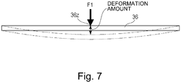
- the rigidity of the doctor blade 36 (alone) will be described using a schematic view of Figure 7 .
- the rigidity of the doctor blade 36 is measured in a state in which the doctor blade 36 is not fixed on the blade mounting portion 41 of the developing device frame 30.
- a concentrated load F1 is exerted in the widthwise direction of the doctor blade 36 on a central portion 36z of the doctor blade 36 with respect to the longitudinal direction of the doctor blade 36.
- the rigidity of the doctor blade 36 (alone) is measured on the basis of an amount of flexure of the doctor blade 36 in the widthwise direction at the central portion 36z of the doctor blade 36.
- the concentrated load F1 of 300 gf is exerted in the widthwise direction of the doctor blade 36 on the central portion 36z of the doctor blade 36 with respect to the longitudinal direction of the doctor blade 36.
- the amount of flexure of the doctor blade 36 in the widthwise direction is 700 ⁇ m or more.
- an amount of deformation in cross-section of the doctor blade 36 at the central portion 36z is 5 ⁇ m or less.
- the rigidity of the developing device frame 30 (alone) will be described using a schematic view of Figure 8 .
- the rigidity of the developing device frame 30 is measured in a state in which the doctor blade 36 is not fixed on the blade mounting portion 41 of the developing device frame 30.
- a concentrated load F1 is exerted in the widthwise direction of the blade mounting portion 41 on a central portion 41z of the blade mounting portion 41 with respect to the longitudinal direction of the blade mounting portion 41.
- the rigidity of the developing device frame 30 is measured on the basis of an amount of flexure of the blade mounting portion 41 in the widthwise direction at the central portion 41z of the blade mounting portion 41.
- the concentrated load F1 of 300 gf is exerted in the widthwise direction of the blade mounting portion 41 on the central portion 41z of the blade mounting portion 41 with respect to the longitudinal direction of the blade mounting portion 41.
- the amount of flexure of the blade mounting portion 41 in the widthwise direction is 60 ⁇ m or less.
- the rigidity of the developing device frame 30 is not less than 10 times higher than the rigidity of the doctor blade 36 (alone). For that reason, in a state in which the doctor blade 36 is mounted on the blade mounting portion 41 of the developing device frame 30 and is fixed on the blade mounting portion 41 of the developing device frame 30, compared with the rigidity of the doctor blade 36, the rigidity of the developing device frame 30 is predominant.
- the rigidity of the doctor blade 36 in a state in which the doctor blade 36 is fixed on the developing device frame 30 becomes high.
- the rigidity of the developing device frame 30 (alone) is larger than the rigidity of the cover frame 40 (alone). For that reason, in a state in which the cover frame 40 is mounted on the developing device frame 30 and is fixed to the developing device frame 30, compared with the rigidity of the cover frame 40, the rigidity of the developing device frame 30 is predominant.
- the SB gap is liable to becomes different with respect to the longitudinal direction of the developer carrying member.
- the SB gap is different with respect to the longitudinal direction of the developer carrying member, there is a liability that with respect to the longitudinal direction of the developer carrying member, non-uniformity of the amount of the developer carried on the surface of the developer carrying member occurs.
- the resin-made doctor blade having a length corresponding to a longitudinal length of an A3-size sheet (hereinafter, this doctor blade is referred to as an A3-size compatible resin-made doctor blade) is manufactured with accuracy of a general purpose resin mold product
- the straightness of the coating amount regulating surface is about 300 ⁇ m - 500 ⁇ m.
- the straightness of the coating amount regulating surface is about 100 ⁇ m - 200 ⁇ m.
- the magnitude of the SB gap G is set at about 300 ⁇ , and a tolerance of the SB gap G (i.e., a tolerance with respect to the target value of the SB gap G) is set at within ⁇ 10 %. Therefore, in this embodiment, this means that an adjusting range of the SB gap G is 300 ⁇ m ⁇ 30 ⁇ m and that an allowable tolerance of the SB gap G is 60 ⁇ m to the maximum. For this reason, even when the A3-size compatible resin-made doctor blade is manufactured with the accuracy of the general purpose resin mold product or is manufactured with high accuracy by using a high-accuracy resin material, only by the accuracy of the straightness of the coating amount regulating surface, a resultant value exceeds an allowable range as the tolerance of the SB gap G.
- the SB gap G falls within a predetermined range over the direction parallel to the rotational axis of the developer carrying member. Therefore, in this embodiment, even when the resin-made doctor blade low in straightness of the coating amount regulating surface, by correcting the straightness of the coating amount regulating surface, in the state in which the doctor blade is fixed to the mounting portion of the developing device frame, the SB gap G is caused to fall within the predetermined range over the direction parallel to the rotational axis of the developing sleeve 70.
- the straightness of the coating amount regulating surface 36r of the doctor blade 36 will be described using a schematic view of Figure 9 .
- the straightness of the coating amount regulating surface 36r of the doctor blade 36 is represented by an absolute value of a difference between a maximum a minimum of an outer configuration of the coating amount regulating surface 36r when a predetermined P of the coating amount regulating surface 36r with respect to the longitudinal direction of the coating amount regulating surface 36r is used as a reference position.
- a central portion of the coating amount regulating surface 36r with respect to the longitudinal direction of the coating amount regulating surface 36r is used as an origin of a rectangular (orthogonal) coordinate system
- a predetermined rectilinear line passing through the origin is X-axis
- a rectilinear line drawn from the origin perpendicularly to the X-axis is Y-axis.
- the straightness of the coating amount regulating surface 36r is represented by an absolute value of a difference between a maximum and a minimum of a Y-coordinate of the outer configuration of the coating amount regulating surface 36r.
- the resin-made doctor blade (alone) has a shape such that with respect to the longitudinal direction of the doctor blade 36, the coating amount regulating surface 36r of the doctor blade 36 largely flexes at the central portion. For that reason, there is a need to correct the straightness of the doctor blade 36 by decreasing a difference among positions of free end portions 36e (36e1 to 36e5). In view of an allowable value of the tolerance of the SB gap G, mounting accuracy of the doctor blade 36 on the developing device frame 30, and the like, the straightness of the coating amount regulating surface 36r of the doctor blade 36 is required to be corrected to 50 ⁇ m or less.
- the straightness of the coating amount regulating surface 36r of the doctor blade 36 may preferably be corrected to 20 ⁇ m or less.
- a setting value of correction of the straightness of the coating amount regulating surface 36r of the doctor blade 36 is about 20 ⁇ m - 50 ⁇ m.
- a force for causing the doctor blade 36 to flex in at least a part of the maximum image region (hereinafter, this force is referred to as a straightness correcting force) is applied to the doctor blade 36, so that the doctor blade 36 is caused to flex in at least the part of the maximum image region.
- the straightness of the coating amount regulating surface 36r of the doctor blade 36 is corrected to not more than 50 ⁇ m.
- outer configurations of the free end portions 36e1 and 36e5 of the doctor blade 36 are used as references, and the straightness correcting force is applied on the basis of the references in arrow I directions to the free end portions 36e2, 36e3 and 36e4 so that outer configurations of the free end portions 36e2, 36e3 and 36e4 coincide with those of the free end portions 36e1 and 36e5.
- the shape of the coating amount regulating surface 36r of the doctor blade 36 is corrected from a coating amount regulating surface 36r1 to a coating amount regulating surface 36r2, so that the straightness of the coating amount regulating surface 36r of the doctor blade can be corrected to not more than 50 ⁇ m.
- the references when the outer configurations of the free end portions 36r of the doctor blade 36 are made the same were the outer configurations of the free end portions 36e1 and 36e5 (longitudinal end portions of the coating amount regulating surface 36r), but may also be the outer configuration of the free end portion 36e3 (longitudinal central portion of the coating amount regulating surface 36r).
- the outer configuration of the free end portion 36e3 of the doctor blade 36 is used as a reference, and the straightness correcting force is applied to the doctor blade 36 so that outer configurations of the free end portions 36e1, 36e2, 36e4 and 36e5 coincide with the of outer configuration of the free end portion 36e3.
- Adjustment of the SB gap G is carried out by moving the position of the doctor blade 36 relative to the developing device frame 30 so that a relative position of the doctor blade 36 mounted on the blade mounting portion 41 is adjusted with respect to the developing sleeve 70 supported by the sleeve supporting portion 42.
- the doctor blade 36 flexed in at least the part of the maximum image region of the doctor blade 36 is fixed with the adhesive A applied over the entire area of the maximum image region of the blade mounting surface 41s in advance.
- the maximum image region of the blade mounting surface 41s refers to a region of the black mounting surface 41s corresponding to a maximum image region of the image region in which the image is formable on the surface of the photosensitive drum 1.
- the doctor blade 36 is fixed to the blade mounting portion 41.
- the adhesive A is not required to be applied onto a part of the blade mounting surface 41s.
- the adhesive A is applied over the entire area of the maximum image region of the blade mounting surface 41s satisfies the following condition.
- the adhesive A is applied in a region which includes the region, of the region corresponding to the maximum image region of the doctor blade 36, in which the doctor blade 36 is flexed for correcting the straightness of the coating amount regulating surface 36r and which is sot less than 95 % of the maximum image region of the blade mounting surface 41s.
- the doctor blade 36 is fixed to the blade mounting portion 41 in a state in which the straightness of the coating amount regulating surface 36r is corrected to not more than 50 ⁇ m.
- the magnitude of the SB gap G is measured (calculated) by a method described below.
- measurement of the magnitude of the SB gap G is carried out in a state in which the developing sleeve 70 is supported by the sleeve supporting portion 42 of the developing device frame 30 and the doctor blade 36 is mounted on the blade mounting portion 41 and in which the cover frame 40 is fixed to the developing device frame 30.
- a light source for example, an LED array, a light guide or the like
- the light source inserted in the developing chamber 31 emits light toward the SB gap G form an inside of the developing chamber 31.
- a camera for picking up a light beam emitted to an outside of the developing device frame 30 through the SB gap G is provided.
- the cameras disposed at the five places pick up light beams emitted to the outside of the developing device frame 30 through the SB gap G in order to measure the respective positions of the free end portions 36e (36e1 to 36e5) of the doctor blade 36.
- the cameras read a closest position of the developing sleeve 70 with the doctor blade 36 on the surface of the developing sleeve 70 and read the free end portions 36e (36e1 to 36e5) of the doctor blade 36.
- pixel values are converted from image data generated by being read with the cameras into distances, so that the magnitude of the SB gap G is calculated. In the case where the calculated magnitude of the SB gap G does not fall within a predetermined range, adjustment of the SB gap G is carried out.
- the position is determined as a position where the doctor blade 36 flexed in at least the part of the maximum image region of the doctor blade 36 is fixed to the blade mounting portion 41 of the developing device frame 30.
- the maximum image region of the doctor blade 36 is equidistantly divided into four or more regions, and in each of the divided regions (but including both end portions and a central portion of the maximum image region of the doctor blade 36), the SB gap G is measured at five places or more. Then, from samples of measured values of the SB gap G measured at five places or more, a maximum value, a minimum value and a median value of the SB gap G are extracted.
- an absolute value of a difference between the maximum value and the median value of the SB gap G may only be required to be not more than 10 % of the median value of the SB gap G, and an absolute value of a difference between the minimum value and the median value of the SB gap G may only be required to be not more than 10 % of the median value of the SB gap G.
- the SB gap G satisfies that the SB gap G falls within the predetermined range over the direction parallel to the rotational axis of the developing sleeve 70.
- the median value of the SB gap G was 300 ⁇ m
- the maximum value of the SB gap G is 330 ⁇ m or less and the minimum value of the SB gap G is 270 ⁇ m or more. That is, in this case, an adjusting range of the SB gap G is 300 ⁇ m ⁇ 30 ⁇ m, so that as the tolerance of the SB gap G (i.e., the tolerance of the SB gap G to the target value), up to 60 ⁇ m at the maximum is permitted.
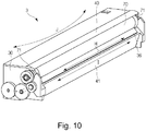
- an elongation amount of the doctor blade 36 due to the temperature change is H ( ⁇ m)
- an elongation amount of the blade mounting surface 41s of the blade mounting portion 41 of the developing device frame 30 is I ( ⁇ m).
- a linear expansion coefficient ⁇ 1 of the resin material constituting the doctor blade 36 and a linear expansion coefficient ⁇ 2 of the resin material contacting the developing device frame 30 are different from each other.
- deformation amounts of the developing device frame 30 and the doctor blade 36 by the temperature changes are different from each other, so that in order to eliminate a difference between H ( ⁇ m) and I ( ⁇ m), the doctor blade 36 deforms in an arrow J direction of Figure 10 .
- the deformation of the doctor blade 36 in the arrow J direction of Figure 10 is referred to as deformation of the doctor blade 36 in a warping direction. Further, the deformation of the doctor blade 36 in the warping direction leads to a fluctuation in magnitude of the SB gap G.
- the linear expansion coefficient ⁇ 2 of the resin material constituting the sleeve supporting portion 42 and the blade mounting portion 41 of the developing device frame 30 (alone) and the linear expansion coefficient ⁇ 1 of the resin material constituting the doctor blade 36 (alone) are associated with each other.
- the resin material is larger in linear expansion coefficient than the metal material.
- the doctor blade 36 is made of the resin material, with the temperature change by the heat generating during the image forming operation, the warping deformation of the doctor blade 36 occurs, so that the doctor blade 36 is liable to flex at the longitudinal central portion.
- the magnitude of the SB gap G is liable to fluctuate with the temperature change during the image forming operation.
- the doctor blade 36 is flexed in at least the part of the maximum image region thereof. Further, a method in which the doctor blade 36 flexed in at least the part of the maximum image region is fixed to the blade mounting portion 41 of the developing device frame 30 with the adhesive A over the entire area of the maximum image region of the doctor blade 36 is employed.
- the magnitude of the SB gap G is fluctuated due to the temperature change during the image forming operation.
- the doctor blade 36 is fixed to the blade mounting surface 41s over the entire area of the maximum image region, and therefore, there is a need to suppress the fluctuation in magnitude of the SB gap G resulting from the temperature change during the image forming operation.
- the fluctuation amount of the SB gap G due to the heat with respect to the longitudinal direction of the developing sleeve 70, in order to suppress non-uniformity of the amount of the developer carried on the surface of the developing sleeve 70, there is a need to suppress the fluctuation amount to not more than ⁇ 20 ⁇ m in general.
- a difference of the linear expansion coefficient ⁇ 2 of the resin material constituting the developing device frame 30 including the sleeve supporting portion 42 and the blade mounting portion 41 from the linear expansion coefficient ⁇ 1 of the resin material constituting the doctor blade 36 is hereinafter referred to as a linear expansion coefficient difference ( ⁇ 2 - ⁇ 1).
- a change in maximum flexure amount of the doctor blade 36 due to this linear expansion coefficient difference ( ⁇ 2 - ⁇ 1) will be described using Table 1.
- measurement of the maximum flexure amount of the doctor blade when the temperature change from a normal temperature (23°C) to a high temperature (40°C) was made was carried out.
- the linear expansion coefficient of the resin material constituting the developing device frame 30 including the sleeve supporting portion 42 and the blade mounting portion 41 is ⁇ 2 (m/°C), and the linear expansion coefficient of the resin material constituting the doctor blade 36 is ⁇ 1 (m/°C). Then, the linear expansion coefficient difference ( ⁇ 2 - ⁇ 1) was changed, and the maximum flexure amount of the doctor blade 36 was measured. A result thereof is shown in Table 1. In Table 1, in the case where the absolute value of the maximum flexure amount is not more than 20 ⁇ m, the maximum flexure amount is evaluated as "o", and in the case where the absolute value of the maximum flexure amount is larger than 20 ⁇ m, the maximum flexure amount is evaluated as "x".
- the resin material constituting the developing device frame 30 and the resin material constituting the doctor blade 36 may only be required to be selected so that the linear expansion coefficient difference ( ⁇ 2- ⁇ 1) is -0.45x10 -5 (m/°C) or more and 0.55x10 -5 (m/°C) or less.
- the same resin material is selected as the resin material constituting the developing device frame 30 and the resin material constituting the doctor blade 36, the linear expansion coefficient difference ( ⁇ 2- ⁇ 1) becomes zero.
- the doctor blade 36 and the developing device frame 30 on which the adhesive A is applied fluctuated fluctuate in linear expansion coefficient.
- a volume itself of the adhesive A applied onto the doctor blade 36 and the developing device frame 30 is very small, so that the influence thereof on a dimensional fluctuation due to the temperature change with respect to a thickness direction of the adhesive A is at a negligible level.
- the adhesive A is applied onto the doctor blade 36 and the developing device frame 30, the deformation of the doctor blade 36 in the warping direction due to the fluctuation in linear expansion coefficient difference ( ⁇ 2- ⁇ 1) is at a negligible level.
- the cover frame 40 is fixed to the developing device frame 30, and therefore, when the deformation amounts of the developing device frame 30 and the cover frame 40 due to the temperature change are different from each other, the deformation of the cover frame 40 in the warping direction heads to the fluctuation in magnitude of the SB gap G.
- the linear expansion coefficient of the resin material constituting the developing device frame 30 including the sleeve supporting portion 42 and the blade mounting portion 41 is ⁇ 2 (m/°C), and the linear expansion coefficient of the resin material constituting the cover frame 40 is ⁇ 3 (m/°C).
- a difference of the linear expansion coefficient ⁇ 3 of the resin material constituting the cover frame 40 from the linear expansion coefficient ⁇ 2 of the resin material constituting the developing device frame 30 including the sleeve supporting portion 42 and the blade mounting portion 41 is hereinafter referred to as a linear expansion coefficient difference ( ⁇ 3- ⁇ 2).
- the resin material constituting the developing device frame 30 and the resin material constituting the cover frame 40 may only be required to be selected so that the linear expansion coefficient difference ( ⁇ 3- ⁇ 2) is -0.45x10 -5 (m/°C) or more and 0.55x10 -5 (m/°C) or less.
- the same resin material is selected as the resin material constituting the developing device frame 30 and the resin material constituting the cover frame 40, the linear expansion coefficient difference ( ⁇ 3- ⁇ 2) becomes zero.
- Figure 11 is the sectional view of the developing device 3 in a cross-section (cross-section H of Figure 2 ) perpendicular to the rotational axis of the developing sleeve 70. Further, Figure 11 shows a structure of a neighborhood of the doctor blade 36 fixed to the blade mounting portion 41 of the developing device frame 30 with the adhesive A.
- a line connecting a closest position of the doctor blade 36 to the developing sleeve 70 on the coating amount regulating surface 36r is X-axis.
- the doctor blade 36 is long in length with respect to the X-axis and is high in rigidity in cross-section along the X-axis.
- a proportion of a cross-sectional area T1 of the doctor blade 36 to a cross-sectional area T2 of a wall portion 30a of the developing device frame 30 positioned in the neighborhood of the developer guiding portion 35 is small.
- the rigidity of the developing device frame 30 (alone) is made higher than the rigidity of the doctor blade 36 (alone) by ten times or more. Accordingly, in a state in which the doctor blade 36 is fixed to the blade mounting portion 41 of the developing device frame 30, the rigidity of the developing device frame 30 is predominant over the rigidity of the doctor blade 36. As a result, during the image forming operation, a displacement amount (maximum flexure amount) of the coating amount regulating surface 36r of the doctor blade 36 when the developer pressure is applied to the doctor blade 36 is substantially equivalent to a displacement amount (maximum flexure amount) of the developing device frame 30.
- the developer scooped from the first feeding screw 33 passes through the developer guiding portion 35 and is fed to the surface of the developing sleeve 70. Thereafter, even when a layer thickness of the developer is regulated to the magnitude of the SB gap G by the doctor blade 36, the doctor blade 36 is subjected to the developer pressure from various directions. As shown in Figure 11 , when a direction perpendicular to the X-axis direction (a direction in which the SB gap G is defined) is a Y-axis direction, the developer pressure along the Y-axis direction is perpendicular to the blade mounting surface 41s of the developing device frame 30.
- the developer pressure with respect to the Y-axis direction is a force for peeling off the doctor blade 36 of the blade mounting surface 41s. Therefore, a binding force by the adhesive A is required to be sufficiently larger than the developer pressure with respect to the Y-axis direction. Therefore, in consideration of the force for peeling off the doctor blade 36 of the blade mounting surface 41s by the developer pressure and of an adhesive force of the adhesive A, an adhesive area and application thickness of the adhesive A onto the blade mounting surface 41s are optimized.
- the developing device including the doctor blade 36 made of the resin material and the developing device frame 30 made of the resin material
- a constitution in which the doctor blade 36 made of the resin material is mounted and fixed to the blade mounting portion 41 of the developing device frame 30 made of the resin material would be considered.
- the longitudinal length of the maximum image region of the doctor blade 36 increases.
- the longitudinal length of the blade mounting surface 41s increases.
- the developing device frame 30 having the blade mounting surface 41s which has a large longitudinal length is molded with a resin material, a degree of unevenness is liable to become large, so that there is a tendency that flatness (JIS B0021) of the blade mounting surface 41s becomes large. This is because in general, with an increasing longitudinal length of the resin molded product, a variation in flatness of the resin molded product is liable to occur with respect to the longitudinal direction of the resin molded product.
- the developing device frame 30 having the blade mounting surface 41s which has a widthwise length larger than a predetermined value is molded with a resin material
- sink marks are liable to generate on the blade mounting surface 41s, so that there is a tendency that the flatness of the blade mounting surface 41s becomes large.
- a degree of generation of a difference in progress of heat contraction between an inside and an outside of the resin molded product becomes large when the resin material which was thermally expanded during molding is thermally contracted.
- the doctor blade 36 made of the resin material is fixed to the developing device frame made of the resin material and having the blade mounting surface 41s which has the large longitudinal length, it is required that the flatness of the blade mounting surface 41s is made small. This is because by decreasing the flatness of the blade mounting surface 41s, the magnitude of the SB gap G is caused to fall within a predetermined range over the longitudinal direction of the developing sleeve 70.
- the flatness of the blade mounting surface 41s can be decreased by subjecting the developing device frame 30 made of the resin material and having the blade mounting surface 41s which has the large longitudinal length to manufacturing and secondary fabrication with high accuracy using a high-precision resin material.
- the developing device frame 30 made of the resin material and having the blade mounting surface 41s which has the large longitudinal length is manufactured with accuracy of a general-purpose resin molded product, in order to decrease the flatness of the blade mounting surface 41s, it would be considered that the widthwise length of the blade mounting surface 41s is made a predetermined value or less.
- the doctor blade 36 is fixed to the developing device frame 30 made of the resin material and having the blade mounting surface 41s which has the widthwise length not more than the predetermined value. That is, an attitude of the resin-made doctor blade 36 mounted on the blade mounting surface 41s when the resin-made doctor blade 36 is fixed to the resin-made developing device frame 30 is stabilized.
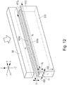
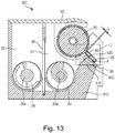
- a constitution of the blade mounting surface in this embodiment will be described using a perspective view of Figure 12 . Further, a constitution of the developing device according to this embodiment will be described using a sectional view of Figure 13 and an enlarged view of Figure 14 .
- Figure 12 shows a phantom state in which the doctor blade 36 is floated from a blade mounting portion 410 and is the perspective view for illustrating a structure of a blade mounting surface 410s.
- Figure 13 is the sectional view of a developing device 300 in a cross section perpendicular to the rotational axis of the developing sleeve 70.
- Figure 14 is a sectional view (enlarged view) of the developing device 300 in the neighborhood (region I of Figure 13 ) of the blade mounting surface 410s.
- the doctor blade 36 is fixed to a developing device frame 310 manufactured with accuracy of the general-purpose resin molded product and having the blade mounting surface 410s which has the large longitudinal length.
- decrease in flatness of the blade mounting surface 410s and stabilization of an attitude of the doctor blade 36 mounted on the blade mounting surface 410s are compatibly realized.
- the developing device frame 310 is provided with a first blade supporting portion (first rib) 420 and a second blade supporting portion (second rib) 430 which are formed along the longitudinal direction (a direction parallel to the rotational axis of the developing sleeve 70) of the developing sleeve 70 at portions thereof projecting from the blade mounting portion 410 and which are provided for supporting the doctor blade 36.
- the first blade supporting portion 420 and the second blade supporting portion 430 are provided at a predetermined interval therebetween.
- the blade mounting surface 410s is constituted by a first blade supporting surface 420s, of the first blade supporting portion 420, capable of supporting the doctor blade 36 and by a second blade supporting surface 430s, of the second blade supporting portion 430, capable of supporting the doctor blade 36.
- the first blade supporting surface 420s is formed over a substantially entire region of the maximum image region of the photosensitive drum 1.
- the second blade supporting surface 420s is formed over an substantially entire region of the maximum image region of the photosensitive drum 1.
- the associated blade supporting surface is regarded as being formed over the substantially entire region of the maximum image region of the photosensitive drum 1.
- a length of the first blade supporting surface 420s with respect to the widthwise direction (i.e., the direction of the doctor blade 36 from the position closest to the developing sleeve 70 toward the rotation center of the developing sleeve 70) of the first blade supporting surface 420s is made 3.0 mm or less.
- a length of the second blade supporting surface 430s with respect to the widthwise direction (i.e., the direction of the doctor blade 36 from the position closest to the developing sleeve 70 toward the rotation center of the developing sleeve 70) of the second blade supporting surface 430s is made 3.0 mm or less.
- the doctor blade 36 is supported by the first blade supporting surface 420s and the second blade supporting surface 430s and thus is mounted on the blade mounting portion 410. Therefore, even when both the length of the first blade supporting surface 420s with respect to the widthwise direction and the length of the second blade supporting surface 430s with respect to the widthwise direction are a predetermined value or less, the attitude of the doctor blade 36 mounted on the blade mounting portion 410 when the doctor blade 36 is fixed to the blade mounting portion 410 is stabilized.
- the magnitude of the SB gap G in a state that the doctor blade 36 is supported by the first blade supporting surface 420s and the second blade supporting surface 430s and thus is mounted on the blade mounting portion 410 can be caused to fall within a predetermined range over the longitudinal direction of the developing sleeve 70.
- x 1 represents a length of the first blade supporting surface 420s with respect to the longitudinal direction of the first blade supporting surface 420s
- y 1 represents a length of the first blade supporting surface 420s with respect to the widthwise direction of the first blade supporting surface 420s
- z 1 represents a length of the first blade supporting portion 420 projecting from the developing device frame 310.
- x 2 represents a length of the second blade supporting surface 430s with respect to the longitudinal direction of the second blade supporting surface 430s
- y 2 represents a length of the second blade supporting surface 430s with respect to the widthwise direction of the second blade supporting surface 430s.
- z 2 represents a length of the second blade supporting portion 430 projecting from the developing device frame 310.
- L represents an interval between the first blade supporting surface 420s and the second blade supporting surface 430s.
- z 1 is 0.2 mm or more, and y 1 is 3.0 mm or less.
- y 1 may preferably be made not more than a basic thickness of the developing device frame 310 and made not less than 0.7 mm.
- z 2 is 0.2 mm or more, and y 2 is 3.0 mm or less.
- y 2 may preferably be made not more than the basic thickness of the developing device frame 310 and made not less than 0.7 mm.
- the basic thickness of the developing device frame 310 is made 1.0 mm or more and 3.0 mm or less.
- the first blade supporting surface 420s is formed over the substantially entire region of the maximum image region of the photosensitive drum 1 and x 1 is about 300 mm.
- the second blade supporting surface 430s is formed over the substantially entire region of the maximum image region of the photosensitive drum 1 and x 2 is about 300 mm.
- z 1 is about 0.5 mm
- z 2 is about 0.5 mm
- L is about 3.0 mm.
- the doctor blade 36 is supported by the first blade supporting portion 420 and the second blade supporting portion 430 and is fixed to the blade mounting portion 410 with the adhesive A.
- the doctor blade 36 is fixed to the blade mounting portion 410 in a flexed state so that the magnitude of the SB gap G falls within the predetermined range over the entire region of the maximum image region of the doctor blade 36.
- the doctor blade 36 may desirably be fixed to the blade mounting portion 410 with the adhesive A over the substantially entire region of a maximum image region of the doctor blade 36.
- the adhesive A may only be required to be applied onto at least one of the first blade supporting surface 420s and the second blade supporting surface 430s.
- the adhesive A is applied on the second blade supporting surface 430s.
- the doctor blade 36 is mounted on the blade mounting portion 410 by being supported by the first blade supporting surface 420s and the second blade supporting surface 430s.
- the doctor blade 36 can be fixed to the blade mounting portion 410 with the adhesive A.
- doctor blade 36 As a means for fixing the doctor blade 36 to the blade mounting portion 410, an example using the adhesive A was described, but the present invention is not limited thereto.
- a modified example in which the doctor blade 36 is fixed to the blade mounting portion 410 by using a double-side tape or welding may also be employed so long as a fixing strength capable of causing the magnitude of the SB gap G to fall within the predetermined range when developer pressure is applied to the doctor blade 36.
- a widthwise length of the surface-to-be-mounted of the regulating blade is made a predetermined value or less.
- the surface-to-be-mounted of the regulating blade refers to a surface of the regulating blade where the regulating blade is to be mounted on the developing device frame.
- a constitution of a blade mounting surface surface-to-be-mounted of a doctor blade in this embodiment will be described using a perspective view of Figure 15 . Further, a constitution of the developing device according to this embodiment will be described using a sectional view of Figure 16 and an enlarged view of Figure 17 .
- Figure 15 shows a phantom state in which a doctor blade 360 is floated from the blade mounting portion 41 and is the perspective view for illustrating a structure of a surface-to-be-mounted (surfaces-to-be-supported 370s and 380s) of the doctor blade 360.
- Figure 16 is the sectional view of a developing device 301 in a cross section perpendicular to the rotational axis of the developing sleeve 70.
- Figure 17 is a sectional view (enlarged view) of the developing device 301 in the neighborhood of the blade surfaces-to-be-supported 370s and 380s of the doctor blade 360.
- the doctor blade 360 is provided with a first portion-to-be-supported (first rib) 370 and a second portion-to-be-supported (second rib) 380 which are formed along the longitudinal direction (a direction parallel to the rotational axis of the developing sleeve 70) of the developing sleeve 70 at portions thereof projecting from a base portion 361 constituted with a basic thickness of the doctor blade 360 and which are provided for being supported by the blade mounting portion 41.
- first rib first rib
- second rib second portion-to-be-supported
- the first portion-to-be-supported 370 and the second portion-to-be-supported 380 are provided at a predetermined interval therebetween.
- the first portion-to-be-supported 370 has a first surface-to-be-supported 370s capable of being supported by the blade mounting portion 41
- the second portion-to-be-supported 380 has a second surface-to-be-supported 380s capable of being supported by the blade mounting portion 41.
- the first surface-to-be-supported 370s is formed over a substantially entire region of the maximum image region of the photosensitive drum 1.
- the second surface-to-be-supported 380s is formed over an substantially entire region of the maximum image region of the photosensitive drum 1.
- the associated blade supporting surface is regarded as being formed over the substantially entire region of the maximum image region of the photosensitive drum 1.
- a length of the first surface-to-be-supported 370s with respect to the widthwise direction (i.e., the direction of the doctor blade 36 from the position closest to the developing sleeve 70 toward the rotation center of the developing sleeve 70) of the first blade supporting surface 420s is made 3.0 mm or less.
- a length of the second surface-to-be-supported 380s with respect to the widthwise direction (i.e., the direction of the doctor blade 36 from the position closest to the developing sleeve 70 toward the rotation center of the developing sleeve 70) of the second blade supporting surface 430s is made 3.0 mm or less.
- each of the first surface-to-be-supported 370s and the second surface-to-be-supported 380s is supported by the blade mounting portion 41, so that the doctor blade 360 is mounted on the blade mounting portion 41. Therefore, even when both the length of the first surface-to-be-supported 370s with respect to the widthwise direction and the length of the second surface-to-be-supported 380s with respect to the widthwise direction are a predetermined value or less, the attitude of the doctor blade 360 mounted on the blade mounting portion 41 when the doctor blade 360 is fixed to the blade mounting portion 41 is stabilized.
- the magnitude of the SB gap G in a state that the first surface-to-be-supported 370s and the second surface-to-be-supported 380s are supported by the blade mounting portion 41 and thus the doctor blade 360 is mounted on the blade mounting portion 41 can be caused to fall within a predetermined range over the longitudinal direction of the developing sleeve 70.
- x' 1 represents a length of the first surface-to-be-supported 370s with respect to the longitudinal direction of the first surface-to-be-supported 370s and y' 1 represents a length of the first surface-to-be-supported 370s with respect to the widthwise direction of the first surface-to-be-supported 370s. Further, z' 1 represents a length of the first portion-to-be-supported 370 projecting from the base portion 361 of the doctor blade 360.
- x' 2 represents a length of the second surface-to-be-supported 380s with respect to the longitudinal direction of the second surface-to-be-supported 380s
- y' 2 represents a length of the second surface-to-be-supported 380s with respect to the widthwise direction of the second surface-to-be-supported 380s
- z' 2 represents a length of the second portion-to-be-supported 380 projecting from the base portion 361 of the doctor blade 360.
- L' represents an interval between the first surface-to-be-supported 370s and the second surface-to-be-supported 380s.
- y' 3 represents an interval between the first portion-to-be-supported 370 and a coating amount regulating surface 360r (position of the doctor blade 360 closest to the developing sleeve 70) as a regulating portion for regulating an amount of the developer carried on the surface of the developing sleeve 70.
- z' 1 is 0.2 mm or more, and y' 1 is 3.0 mm or less.
- y' 1 may preferably be made not more than a basic thickness of developing device frame 310 and made not less than 0.7 mm.
- z' 2 is 0.2 mm or more, and y' 2 is 3.0 mm or less.
- y' 2 may preferably be made not more than the basic thickness of the doctor blade 360 and made not less than 0.7 mm.
- the basic thickness of the doctor blade 360 is made 1.0 mm or more and 3.0 mm or less.
- the first surface-to-be-supported 370s is formed over the substantially entire region of the maximum image region of the photosensitive drum 1 and x' 1 is about 300 mm.
- the second surface-to-be-supported 380s is formed over the substantially entire region of the maximum image region of the photosensitive drum 1 and x' 2 is about 300 mm.
- z' 1 is about 0.5 mm
- z' 2 is about 0.5 mm
- L' is about 3.0 mm.
- y' 3 is 0.6 mm or more. This is because even in the case where sink marks generate on the doctor blade 360 due to the first portion-to-be-supported 370 when the doctor blade 360 is molded with a resin material, an influence of the sink marks on the coating amount regulating surface 360r is reduced. That is, by making y' 3 not less than 0.6 mm, the magnitude of the SB gap G can be caused to fall within the predetermined range over the longitudinal direction of the developing sleeve 70.
- the first portion-to-be-supported 370 and the second portion-to-be-supported 380 are supported by the blade mounting portion 41, so that the doctor blade 360 is fixed to the blade mounting portion 41 with the adhesive A.
- the doctor blade 360 is fixed to the blade mounting portion 41 in a flexed state so that the magnitude of the SB gap G falls within the predetermined range over the entire region of the maximum image region of the doctor blade 360.
- the doctor blade 360 may desirably be fixed to the blade mounting portion 41 with the adhesive A over the substantially entire region of a maximum image region of the doctor blade 360.
- the adhesive A may only be required to be applied onto at least one of the first surface-to-be-supported 370s and the second surface-to-be-supported 380s.
- the adhesive A is applied on the second surface-to-be-supported 380s.
- the doctor blade 360 is mounted on the blade mounting portion 41 by supporting the first surface-to-be-supported 370s and the second surface-to-be-supported 380s by the blade mounting portion 41.
- the doctor blade 360 can be fixed to the blade mounting portion 410 with the adhesive A.
- doctor blade 360 as a means for fixing the doctor blade 360 to the blade mounting portion 41, an example using the adhesive A was described, but the present invention is not limited thereto.
- a modified example in which the doctor blade 360 is fixed to the blade mounting portion 41 by using a double-side tape or welding may also be employed so long as a fixing strength capable of causing the magnitude of the SB gap G to fall within the predetermined range when developer pressure is applied to the doctor blade 360.
- Second Embodiment described above in the constitution in which the doctor blade with the accuracy of the general-purpose is fixed to the developing device frame made of the resin material, the decrease in flatness of the surface-to-be-mounted (surface-to-be-supported) of the doctor blade and the stabilization of the attitude of the doctor blade mounted on the blade mounting surface of the developing device frame were compatibly realized.
- Second Embodiment by a simple constitution, the attitude of the doctor blade mounted on the blade mounting surface when the doctor blade made of the resin material is fixed to the developing device frame made of the resin material can be stabilized while decreasing the flatness of the surface-to-be-mounted (surface-to-be-supported) of the doctor blade.
- the doctor blade is provided with the first portion-to-be-supported and the second portion-to-be-supported, and therefore, geometrical moment of inertia of the doctor blade increases due to the first portion-to-be-supported and the second portion-to-be-supported, so that rigidity of the doctor blade increases.
- the developing device frame is provided with the first blade supporting portion and the second blade supporting portion, and therefore, different from this embodiment, there is no need that the doctor blade is provided with the first portion-to-be-supported and the second portion-to-be-supported. For this reason, in First Embodiment, rigidity of the doctor blade can be made lower than the rigidity of the doctor blade in this embodiment.
- the doctor blade is fixed to the blade mounting portion of the developing device frame in a state that the doctor blade is flexed so that the magnitude of the SB gap G falls within the predetermined range over the entire region of the maximum image region of the doctor blade.
- the doctor blade With lower rigidity of the doctor blade, the doctor blade is flexed more easily without increasing a force (straightness correcting force) to be imparted to the doctor blade for flexing the doctor blade. Therefore, so long as the developing device is assembled through a step of flexing the doctor blade, from a viewpoint of an assembling property of the doctor blade.
- First Embodiment capable of lowering the rigidity of the doctor blade is more advantageous than Second Embodiment.
- a metal mold in order to lower the rigidity of the doctor blade for the purpose of flexing the doctor blade, a metal mold is designed so that a cross-sectional area of the doctor blade is relatively decreased for decreasing geometrical moment of inertia.
- the metal mold designed so as to decrease the cross-sectional area of the doctor blade is used, molding pressure has to be increased so that a melted resin material efficiently flows in the metal mold. This is because the melted resin material does not readily flow more smoothly with a decreasing cross-sectional area of a space in which the melted resin material passes. In other words, the melted resin material easily flows more smoothly with an increasing cross-sectional area of the space in which the melted resin material passes.
- the doctor blade is provided with the first portion-to-be-supported and the second portion-to-be-supported, so that in this embodiment, the cross-sectional area of the doctor blade can be made larger than that in First Embodiment. Therefore, so long as the doctor blade is molded with the resin material in the metal mold designed so as to relatively decrease the cross-sectional area of the doctor blade, from a viewpoint of a molding property of the doctor blade, Second Embodiment capable of increasing the cross-sectional area of the doctor blade is more advantageous than First Embodiment.
- the longitudinal length of the maximum image region of the doctor blade 36 becomes large correspondingly to the increase in width of the sheet S on which the image is to be formed.
- the doctor blade 36 large in longitudinal length is molded with a resin material, it is difficult to ensure the straightness of the coating amount regulating surface 36r of the doctor blade 36 made of resin material. Therefore, in this embodiment, in order to correct the straightness of the coating amount regulating surface 36r of the doctor blade 36 having the large longitudinal length to 50 ⁇ m or less, at least a part of the maximum image region of the doctor blade 36 is flexed. Then, a method in which the doctor blade 36 having the maximum image region flexed at least at the part thereof is mounted on the blade mounting portion 41 of the developing device frame 30 and then is fixed to the blade mounting portion 41 with the adhesive A is employed.
- the doctor blade 36 may desirably be fixed to the blade mounting portion 41 with the adhesive A over the substantially entire region of the maximum image region of the doctor blade 36.
- the adhesive A having a predetermined thickness is, for example, applied onto the blade mounting surface 41s of the blade mounting portion 41. Further, when the doctor blade 36 is mounted on the blade mounting portion 41 (during adhesive bonding), predetermined pressure is applied to the doctor blade 36, so that the adhesive A having the predetermined thickness is pressed (deformed). At this time, there is a liability that the adhesive (excessive adhesive) escaping to an outside of the surface (the blade mounting surface 41s in this case) on which the adhesive A is applied enters an inside of the developing device frame 30.
- a constitution of the developing device according to this embodiment will be described using a sectional view of Figure 18 and a sectional view (enlarged view) of Figure 19 .
- Figure 18 is the sectional view of a developing device 300 in a cross section perpendicular to the rotational axis of the developing sleeve 70.
- Figure 19 is the sectional view of the developing device 300 in the cross section perpendicular to the rotational axis of the developing sleeve 70 and is the enlarged view of the developing device 300 in the neighborhood (region I of Figure 18 ) of the blade mounting portion 410 (especially, the blade mounting surface 410s) of a developing device frame 310.
- constituent elements to which the same reference numerals or symbols as those in Figure 4 are added are the same as those in Figure 4 .
- a difference from the constitution of the developing device 3 described above with reference to Figure 4 will be principally described.
- the blade mounting portion 410 is provided with a first blade supporting portion 420 and a second blade supporting portion 430 which project from the developing device frame 310 and which are provided for supporting the doctor blade 36 with an interval therebetween.
- the blade mounting surface 410s is constituted by a first blade supporting surface 420s, of the first blade supporting portion 420, capable of supporting the doctor blade 36 and by a second blade supporting surface 430s, of the second blade supporting portion 430, capable of supporting the doctor blade 36.
- a shortest distance between the developing sleeve 70 and the second blade supporting surface 430s is longer than a shortest distance between the developing sleeve 70 and the first blade supporting surface 420s.
- the first blade supporting surface 420s is formed over a substantially entire region of the maximum image region of the blade mounting surface 410s. Further, in this embodiment, the second blade supporting surface 420s is formed over an substantially entire region of the maximum image region of the blade mounting surface 410s.
- the associated blade supporting surface is regarded as being formed over the substantially entire region of the maximum image region of the blade mounting surface 410s.
- a groove portion 440 as a recessed portion recessed from each of the first blade supporting surface 420s and the second blade supporting surface 430s by 0.2 mm or more is formed between the first blade supporting portion 420 and the second blade supporting portion 430.
- the groove portion 440 performs a function as a predetermined space for storing the adhesive (excessive adhesive) A escaping to the outside of the surface on which the adhesive A is applied when the doctor blade 36 is mounted on the blade mounting portion 410.
- the groove portion 440 is formed over the substantially entire region of the maximum image region of the blade mounting surface 410s.
- the groove portion 440 is regarded as being formed over the substantially entire region of the maximum image region of the blade mounting surface 410s.
- the adhesive A is applied on the second blade supporting surface 430s positioned on a side remote from the developing sleeve, but is not applied on the first blade supporting surface 420s positioned on a side close to the developing sleeve 70.
- a widthwise length of the second blade supporting surface 430s is 1.5 mm, and a height of the adhesive A applied onto the second blade supporting surface 430s is 800 ⁇ m.
- an interval between the first blade supporting portion 420 and the second blade supporting portion 430 i.e., a width of the groove portion 440
- an amount of a recess i.e., a depth of the groove portion 440 from the blade mounting surface 410s (from each of the first blade supporting surface 420s and the second blade supporting surface 430s) is 0.4 mm.
- a film thickness of the cured adhesive is about 20 - 100 ⁇ m which is a film thickness capable of ensuring sufficient adhesive strength.
- a volume of the groove portion 440 is larger than a volume of the adhesive A applied on the second blade supporting surface 430s.
- a total value of an area of a region where the adhesive A is applied on the blade mounting surface 410s (the second blade supporting surface 430s in this embodiment) is S 1 (mm 2 ), and a film thickness of the adhesive A when the adhesive A applied on the second blade supporting surface 430s is cured is t (mm).
- a volume of the adhesive A applied on the second blade supporting surface 430s is S 1 x t (mm 3 ).
- a longitudinal length of the groove portion 440 is L (mm)
- a cross-sectional area of the groove portion 440 in a cross section perpendicular to the rotational axis of the developing sleeve 70 is S 2 (mm 2 ).
- a volume of the groove portion 440 is S 2 x L (mm 3 ). Further, by satisfying a relationship of S 2 x L (mm 3 ) > S 1 x t (mm 3 ), this relationship means that the volume of the groove portion 440 is larger than the volume of the adhesive A applied on the second blade supporting surface 430s.
- the adhesive A is applied on the second blade supporting surface 430s positioned on the side remote from the developing sleeve 70, but it is desirable that the adhesive A is not applied on the first blade supporting surface 420s close to the developing sleeve 70. This is because in the case where the adhesive A is applied on the first blade supporting surface 420s, when the doctor blade 36 is mounted on the blade mounting portion 410, there is a possibility that a part of the adhesive escaping to the outside of the first blade supporting surface 420s enters the inside of the developing device frame 310.
- a constitution of a developing device according to this embodiment will be described using a sectional view of Figure 20 and a sectional view
- Figure 20 is the sectional view of a developing device 301 in a cross section perpendicular to the rotational axis of the developing sleeve 70.
- Figure 21 is the sectional view of the developing device 301 in the cross section perpendicular to the rotational axis of the developing sleeve 70 and is the enlarged view of the developing device 301 in the neighborhood of the blade mounting portion 41 (especially, the blade mounting surface 41s) of a developing device frame 30.
- constituent elements to which the same reference numerals or symbols as those in Figures 4 , 18 and 19 are added are the same as those in Figures 4 , 18 and 19 .
- a difference from the constitution of the developing device 300 described above with reference to Figures 4 , 18 and 19 will be principally described.
- a doctor blade 360 is provided with a first blade contact portion (first portion-to-be-supported) 370 and a second blade contact portion (second portion-to-be-supported) 380 which are portions where the doctor blade 360 contacts the blade mounting portion 41 when the doctor blade 360 is mounted on the blade mounting portion 41 and which are provided with an interval therebetween.
- a shortest distance between the developing sleeve 70 and the second blade contact portion 380 is longer than a shortest distance between the developing sleeve 70 and the first blade contact portion 370.
- a groove portion 390 as a recessed portion recessed from each of the first blade contact surface (first surface-to-be-supported) 370s and the second (second surface-to-be-supported) 380s by 0.2 mm or more is formed between the first blade contact portion 370 and the second blade contact portion 380.
- the first blade contact surface 370s is a surface of the first blade contact portion 370 contacting the blade mounting portion 410
- the second blade contact surface 380s is a surface of the second blade contact portion 380 contacting the blade mounting portion 410.
- the groove portion 390 performs a function as a predetermined space for storing the adhesive (excessive adhesive) A escaping to the outside of the surface on which the adhesive A is applied when the doctor blade 360 is mounted on the blade mounting portion 41.
- the groove portion 390 is formed over the substantially entire region of the maximum image region of the doctor blade 360.
- the groove portion 390 is regarded as being formed over the substantially entire region of the maximum image region of the doctor blade 360.
- the adhesive A is applied on the second blade contact surface 380s positioned on a side remote from the developing sleeve, but is not applied on the first blade contact surface 370s positioned on a side close to the developing sleeve 70.
- a volume of the groove portion 390 is larger than a volume of the adhesive A applied on the second blade contact surface 380s.
- the adhesive A is applied on the second blade contact surface 380s positioned on the side remote from the developing sleeve 70, but it is desirable that the adhesive A is not applied on the first blade contact surface 370s close to the developing sleeve 70. This is because in the case where the adhesive A is applied on the first blade contact surface 370s, when the doctor blade 360 is mounted on the blade mounting portion 41, there is a possibility that a part of the adhesive escaping to the outside of the first blade contact surface 370s enters the inside of the developing device frame 30.
- FIG. 22 is the sectional view of the developing device 302 in the cross section perpendicular to the rotational axis of the developing sleeve 70 and is the enlarged view of the developing device 302 in the neighborhood of the blade mounting portion 410 (especially, the blade mounting surface 410s) of a developing device frame 310.
- constituent elements to which the same reference numerals or symbols as those in Figures 19 and 21 are added are the same as those in Figures 19 and 21 .
- a difference from the constitution of the developing devices 300 and 301 described above with reference to Figures 19 and 21 , respectively, will be principally described.
- a groove portion 440 as a recessed portion recessed from each of the first blade supporting surface 420s and the second blade supporting surface 430s by 0.2 mm or more is formed between the first blade supporting portion 420 and the second blade supporting portion 430.
- a groove portion 390 as a recessed portion recessed from each of the first blade contact surface (first surface-to-be-supported) 370s and the second (second surface-to-be-supported) 380s by 0.2 mm or more is formed between the first blade contact portion (first portion-to-be-supported) 370 and the second blade contact portion (second portion-to-be-supported) 380.
- each of the groove portion 440 and the groove portion 390 performs a function as a predetermined space for storing the adhesive (excessive adhesive) A escaping to the outside of the surface on which the adhesive A is applied when the doctor blade 360 is mounted on the blade mounting portion 410.
- the groove portion 440 of the blade mounting portion 410 is formed over the substantially entire region of the maximum image region of the blade mounting surface 410s
- the groove portion 390 of the doctor blade 360 is formed over the substantially entire region of the maximum image region of the doctor blade 360.
- the adhesive A is applied on the second blade supporting surface 430s and the second blade contact surface 380s which are positioned on a side remote from the developing sleeve, but is not applied on the first blade supporting surface 420s and the first blade contact surface 370s which are positioned on a side close to the developing sleeve 70.
- a total volume of the groove portion 440 of the blade mounting portion 410 and the groove portion 390 is larger than a total volume of the adhesive A applied on the second blade supporting surface 430s and the second blade contact surface 380s.
- the groove portion for forming the predetermined space for storing the excessive adhesive is not provided in advance on any of the blade mounting portion and the doctor blade.
- a predetermined space for storing the adhesive (excessive adhesive) A escaping to the outside of the adhesive applied surface is first formed when the doctor blade is mounted on the blade mounting portion will be described.
- Figure 23 is the sectional view of the developing device 303 in the cross section perpendicular to the rotational axis of the developing sleeve 70 and is the enlarged view of the developing device 303 in the neighborhood of the blade mounting portion 4100 (especially, the blade mounting surface 4100s) of a developing device frame 3100.
- constituent elements to which the same reference numerals or symbols as those in Figures 19 , 21 and 22 are added are the same as those in Figures 19 , 21 and 22 .
- a difference from the constitution of the developing devices 300, 301 and 302 described above with reference to Figures 19 , 21 and 22 , respectively, will be principally described.
- a predetermined space 3900 for storing the adhesive escaping to the outside of the adhesive applied surface is first formed between the blade mounting portion 4100 and the doctor blade 3600.
- a volume of the predetermined space 3900 for storing the excessive adhesive is larger than a volume of the adhesive applied on the blade mounting portion 4100 and the doctor blade 3600.
- the image forming apparatus 60 having a constitution in which the intermediary transfer belt 61 is used as the intermediary transfer member was described as an example, but the present invention is not limited thereto.
- the present invention is also applicable to an image forming apparatus having a constitution in which transfer of the image is carried out by causing a recording material to directly contact the photosensitive drum 1 successively.
- the developing device 300 was described as a single unit, but a similar effect can be obtained even in the form of a process cartridge which is prepared by integrally assembling the image forming portion 600 ( Figure 1 ) including the developing device 300 into a unit and which is detachably mountable to the image forming apparatus 60. Further, when the image forming apparatus 60 includes the developing device 300 or the process cartridge, the present invention is applicable irrespective of a monochromatic (image forming) machine and a color (image forming) machine.
- first and second ribs When a developing device including a developer carrying member, a regulating blade, and a developing device frame including first and second ribs is seen in a cross section perpendicular to a rotational axis of the developer carrying member, the first and second ribs are provided at a predetermined gap in a direction from a position where the regulating blade is closest to the developer carrying member toward a rotation center of the developer carrying member.
- the first and second ribs have first and second supporting surfaces, respectively, each supporting the regulating blade and having a width of 3.0 mm or less. In a state that the regulating blade is supported by the first and second supporting surfaces, the regulating blade is fixed to the mounting portion in a region of the regulating blade corresponding to a maximum image region of an image bearing member.
Landscapes
- Physics & Mathematics (AREA)
- General Physics & Mathematics (AREA)
- Dry Development In Electrophotography (AREA)
Applications Claiming Priority (3)
| Application Number | Priority Date | Filing Date | Title |
|---|---|---|---|
| JP2017224977 | 2017-11-22 | ||
| JP2017224976A JP7009178B2 (ja) | 2017-11-22 | 2017-11-22 | 現像装置 |
| JP2018190016A JP7195860B2 (ja) | 2017-11-22 | 2018-10-05 | 現像装置 |
Publications (3)
| Publication Number | Publication Date |
|---|---|
| EP3489757A2 true EP3489757A2 (de) | 2019-05-29 |
| EP3489757A3 EP3489757A3 (de) | 2019-06-19 |
| EP3489757A8 EP3489757A8 (de) | 2019-07-10 |
Family
ID=64270665
Family Applications (1)
| Application Number | Title | Priority Date | Filing Date |
|---|---|---|---|
| EP18205335.5A Withdrawn EP3489757A3 (de) | 2017-11-22 | 2018-11-09 | Entwicklungsvorrichtung |
Country Status (4)
| Country | Link |
|---|---|
| US (1) | US10620564B2 (de) |
| EP (1) | EP3489757A3 (de) |
| KR (1) | KR20190059245A (de) |
| CN (1) | CN109814351B (de) |
Families Citing this family (1)
| Publication number | Priority date | Publication date | Assignee | Title |
|---|---|---|---|---|
| JP2020134691A (ja) * | 2019-02-19 | 2020-08-31 | 京セラドキュメントソリューションズ株式会社 | 現像装置及び画像形成装置 |
Citations (1)
| Publication number | Priority date | Publication date | Assignee | Title |
|---|---|---|---|---|
| JP2014197175A (ja) | 2013-03-05 | 2014-10-16 | キヤノン株式会社 | 現像装置 |
Family Cites Families (7)
| Publication number | Priority date | Publication date | Assignee | Title |
|---|---|---|---|---|
| JPH08160743A (ja) | 1994-12-09 | 1996-06-21 | Canon Inc | 現像装置 |
| EP0798748B1 (de) * | 1996-03-28 | 2000-08-02 | Lexmark International, Inc. | Elektrisches Kontaktmaterial für flexible Abstreichklinge |
| JPH11282251A (ja) * | 1998-03-30 | 1999-10-15 | Canon Inc | 現像装置及びプロセスカートリッジ |
| JP2010134257A (ja) | 2008-12-05 | 2010-06-17 | Canon Chemicals Inc | 現像剤量規制ブレード |
| KR101777346B1 (ko) | 2010-08-11 | 2017-09-27 | 에스프린팅솔루션 주식회사 | 현상기 및 이를 채용한 화상형성장치 |
| JP6253300B2 (ja) | 2013-08-09 | 2017-12-27 | キヤノン株式会社 | 現像装置、及びプロセスカートリッジ |
| JP2017203814A (ja) | 2016-05-09 | 2017-11-16 | 株式会社リコー | 現像装置、プロセスユニット、画像形成装置 |
-
2018
- 2018-11-08 US US16/183,973 patent/US10620564B2/en active Active
- 2018-11-09 EP EP18205335.5A patent/EP3489757A3/de not_active Withdrawn
- 2018-11-21 KR KR1020180144400A patent/KR20190059245A/ko not_active Ceased
- 2018-11-22 CN CN201811394485.1A patent/CN109814351B/zh active Active
Patent Citations (1)
| Publication number | Priority date | Publication date | Assignee | Title |
|---|---|---|---|---|
| JP2014197175A (ja) | 2013-03-05 | 2014-10-16 | キヤノン株式会社 | 現像装置 |
Also Published As
| Publication number | Publication date |
|---|---|
| CN109814351A (zh) | 2019-05-28 |
| EP3489757A8 (de) | 2019-07-10 |
| US10620564B2 (en) | 2020-04-14 |
| EP3489757A3 (de) | 2019-06-19 |
| KR20190059245A (ko) | 2019-05-30 |
| US20190155187A1 (en) | 2019-05-23 |
| CN109814351B (zh) | 2022-05-10 |
Similar Documents
| Publication | Publication Date | Title |
|---|---|---|
| US10705450B2 (en) | Method of fixing regulating blade made of resin material | |
| US10564566B2 (en) | Developing device with a regulation blade mounted seal member | |
| EP3489757A2 (de) | Entwicklungsvorrichtung | |
| US10747141B2 (en) | Developing device | |
| CN114706283B (zh) | 制造显影装置的方法 | |
| US10514628B2 (en) | Developing device including a resin-made regulating blade | |
| US10761452B2 (en) | Developing device including a resin regulating blade | |
| JP7009178B2 (ja) | 現像装置 | |
| US10545428B2 (en) | Method of fixing regulating blade and development device | |
| US10775714B2 (en) | Developing device | |
| JP7195860B2 (ja) | 現像装置 | |
| JP7146512B2 (ja) | 現像装置 | |
| JP7146511B2 (ja) | 現像装置 | |
| US10698340B2 (en) | Method of attaching regulating blade and development apparatus | |
| KR102179333B1 (ko) | 규제 블레이드 고정 방법 및 현상 장치 |
Legal Events
| Date | Code | Title | Description |
|---|---|---|---|
| PUAI | Public reference made under article 153(3) epc to a published international application that has entered the european phase |
Free format text: ORIGINAL CODE: 0009012 |
|
| STAA | Information on the status of an ep patent application or granted ep patent |
Free format text: STATUS: THE APPLICATION HAS BEEN PUBLISHED |
|
| PUAL | Search report despatched |
Free format text: ORIGINAL CODE: 0009013 |
|
| AK | Designated contracting states |
Kind code of ref document: A2 Designated state(s): AL AT BE BG CH CY CZ DE DK EE ES FI FR GB GR HR HU IE IS IT LI LT LU LV MC MK MT NL NO PL PT RO RS SE SI SK SM TR |
|
| AX | Request for extension of the european patent |
Extension state: BA ME |
|
| AK | Designated contracting states |
Kind code of ref document: A3 Designated state(s): AL AT BE BG CH CY CZ DE DK EE ES FI FR GB GR HR HU IE IS IT LI LT LU LV MC MK MT NL NO PL PT RO RS SE SI SK SM TR |
|
| AX | Request for extension of the european patent |
Extension state: BA ME |
|
| RIC1 | Information provided on ipc code assigned before grant |
Ipc: G03G 15/08 20060101AFI20190516BHEP |
|
| STAA | Information on the status of an ep patent application or granted ep patent |
Free format text: STATUS: REQUEST FOR EXAMINATION WAS MADE |
|
| 17P | Request for examination filed |
Effective date: 20191219 |
|
| RBV | Designated contracting states (corrected) |
Designated state(s): AL AT BE BG CH CY CZ DE DK EE ES FI FR GB GR HR HU IE IS IT LI LT LU LV MC MK MT NL NO PL PT RO RS SE SI SK SM TR |
|
| STAA | Information on the status of an ep patent application or granted ep patent |
Free format text: STATUS: THE APPLICATION HAS BEEN WITHDRAWN |
|
| 18W | Application withdrawn |
Effective date: 20210426 |