EP3489158B1 - Auflageteller zum positionieren von behältern - Google Patents
Auflageteller zum positionieren von behältern Download PDFInfo
- Publication number
- EP3489158B1 EP3489158B1 EP18199557.2A EP18199557A EP3489158B1 EP 3489158 B1 EP3489158 B1 EP 3489158B1 EP 18199557 A EP18199557 A EP 18199557A EP 3489158 B1 EP3489158 B1 EP 3489158B1
- Authority
- EP
- European Patent Office
- Prior art keywords
- support plate
- container
- inner guide
- guide portion
- plate according
- Prior art date
- Legal status (The legal status is an assumption and is not a legal conclusion. Google has not performed a legal analysis and makes no representation as to the accuracy of the status listed.)
- Active
Links
Images

Classifications
-
- B—PERFORMING OPERATIONS; TRANSPORTING
- B65—CONVEYING; PACKING; STORING; HANDLING THIN OR FILAMENTARY MATERIAL
- B65C—LABELLING OR TAGGING MACHINES, APPARATUS, OR PROCESSES
- B65C9/00—Details of labelling machines or apparatus
- B65C9/02—Devices for moving articles, e.g. containers, past labelling station
- B65C9/04—Devices for moving articles, e.g. containers, past labelling station having means for rotating the articles
-
- B—PERFORMING OPERATIONS; TRANSPORTING
- B41—PRINTING; LINING MACHINES; TYPEWRITERS; STAMPS
- B41J—TYPEWRITERS; SELECTIVE PRINTING MECHANISMS, i.e. MECHANISMS PRINTING OTHERWISE THAN FROM A FORME; CORRECTION OF TYPOGRAPHICAL ERRORS
- B41J3/00—Typewriters or selective printing or marking mechanisms characterised by the purpose for which they are constructed
- B41J3/407—Typewriters or selective printing or marking mechanisms characterised by the purpose for which they are constructed for marking on special material
- B41J3/4073—Printing on three-dimensional objects not being in sheet or web form, e.g. spherical or cubic objects
- B41J3/40731—Holders for objects, e. g. holders specially adapted to the shape of the object to be printed or adapted to hold several objects
-
- B—PERFORMING OPERATIONS; TRANSPORTING
- B41—PRINTING; LINING MACHINES; TYPEWRITERS; STAMPS
- B41J—TYPEWRITERS; SELECTIVE PRINTING MECHANISMS, i.e. MECHANISMS PRINTING OTHERWISE THAN FROM A FORME; CORRECTION OF TYPOGRAPHICAL ERRORS
- B41J3/00—Typewriters or selective printing or marking mechanisms characterised by the purpose for which they are constructed
- B41J3/407—Typewriters or selective printing or marking mechanisms characterised by the purpose for which they are constructed for marking on special material
- B41J3/4073—Printing on three-dimensional objects not being in sheet or web form, e.g. spherical or cubic objects
- B41J3/40733—Printing on cylindrical or rotationally symmetrical objects, e. g. on bottles
-
- B—PERFORMING OPERATIONS; TRANSPORTING
- B65—CONVEYING; PACKING; STORING; HANDLING THIN OR FILAMENTARY MATERIAL
- B65B—MACHINES, APPARATUS OR DEVICES FOR, OR METHODS OF, PACKAGING ARTICLES OR MATERIALS; UNPACKING
- B65B43/00—Forming, feeding, opening or setting-up containers or receptacles in association with packaging
- B65B43/42—Feeding or positioning bags, boxes, or cartons in the distended, opened, or set-up state; Feeding preformed rigid containers, e.g. tins, capsules, glass tubes, glasses, to the packaging position; Locating containers or receptacles at the filling position; Supporting containers or receptacles during the filling operation
- B65B43/54—Means for supporting containers or receptacles during the filling operation
- B65B43/60—Means for supporting containers or receptacles during the filling operation rotatable
-
- B—PERFORMING OPERATIONS; TRANSPORTING
- B65—CONVEYING; PACKING; STORING; HANDLING THIN OR FILAMENTARY MATERIAL
- B65C—LABELLING OR TAGGING MACHINES, APPARATUS, OR PROCESSES
- B65C9/00—Details of labelling machines or apparatus
- B65C9/06—Devices for presenting articles in predetermined attitude or position at labelling station
Definitions
- the invention relates to a support plate according to the preamble of claim 1, a treatment machine with at least one support plate and a manufacturing method for the support plate.
- a support plate is, for example, from the DE 20 2015 103853 U1 and the EP 2 746 176 A1 known and preferably used in combination with a rotary drive as a turntable for positioning containers on container tables of labeling machines and / or direct printing machines.
- Such support plates are then, for example, equipped with individual servomotors and arranged uniformly along the circumference of the container table.
- the support plate EP 2 746 176 A1 has a base plate and a support plate for a container bottom that is elastically supported on it by means of compression springs.
- the support plate is also surrounded by a guide ring standing on separate compression springs. This has a chamfer along its inner leading edge and allows containers to be set down on the support plate even with base cross-sections which, due to dimensional tolerances, also partially rest on the inner leading edge.
- the guide ring is pressed downwards by the bottom of the container against the restoring force of the compression springs until the bottom of the container is on the support plate.
- the guide ring also centers the container with respect to the support plate.
- EP 2 746 176 A1 mentions a support plate according to the preamble of claim 1 as prior art.
- the task is solved with a support plate according to claim 1. Accordingly, this serves to position containers, in particular on rotating container tables.
- the support plate comprises a base body, a support plate for a container that is spring-loaded downwards and a guide ring enclosing the support plate with an inner guide section for circumferential guidance of the container and with an outer attachment section for rigid attachment
- the inner guide section is elastically deformable in relation to the outer fastening section of the guide ring towards the base body.
- the outer fastening section and thus the entire guide ring is rigidly fastened to the base body in a comparatively simple manner. Fewer individual parts are required. It is correspondingly easy to replace the guide ring, for example when changing format, i.e. to adapt to containers with a different bottom cross-section.
- the outside of the guide ring can be designed with fewer gaps and other surfaces that are difficult to clean.
- an elastic deformability of the inner guide section can be achieved in particular in that it has a lower rigidity than the outer fastening section.
- the inner guide section includes, for example, areas with a targeted material weakening and/or material recess.
- the inner guide section comprises at least three segments that are partially circumferential and elastically deformable separately from one another.
- a subdivision into four to eight partial circumferential segments that are elastically deformable separately from one another is particularly preferred. This facilitates a uniform and in particular centering deformation of the segments towards the base body.
- the segmentation allows the material tension in the inner guide section to be specifically adapted to the cross-section of the container bottom during elastic deformation, for example for non-round cross-sections.
- the inner guide section preferably comprises at least one guide lip angled towards the base body.
- the guide lip may include a circumferential chamfer on its top. The angling of the guide lip facilitates centering of the container guided by the inner guide section with respect to the central axis of the support plate.
- the outer fastening section is preferably designed as an upper stop for the support plate.
- the support plate is preferably supported on the base body by means of at least one compression spring.
- the at least one compression spring then presses the support plate axially away from the base body and against the guide ring.
- the unloaded resting position of the support plate can be at a defined height level with respect to the base body specify exactly.
- the outer attachment portion includes outer sidewall portions for anti-tampering.
- the anti-tamper device is then preferably integrated into the guide ring in one piece, but could also be attached to it by means of a snap connection or the like.
- the outer side wall areas then preferably also serve to shield against dust and/or liquids.
- At least the inner guide section of the guide ring consists of a material produced additively using 3D printing.
- the guide section then consists of a layered plastic or metal-plastic composite, such as alumide.
- a layered plastic or metal-plastic composite such as alumide.
- comparatively complex structures such as undercuts, recesses, reinforcements or the like can be produced in order to form inner guide sections with suitable rigidity and elasticity and to adapt them to given container cross sections.
- the inner guide section can then deform elastically in a suitable manner and center the container bottom.
- a generative production of the entire guide ring in 3D printing from at least one plastic and/or metal-plastic composite as described above is particularly advantageous.
- the inner guide section and the outer fastening section can also consist of different 3D printing materials.
- At least the inner guide section essentially consists of a thermoplastic material and, in a contact area with the containers, comprises an outer contact layer that is separately colored up to a permissible wear depth.
- a contact layer can advantageously be produced additively, that is to say by 3D printing, by printing the contact layer onto a support structure with a separate color.
- the supporting structure lying under the contact layer is manufactured in a different color, in particular additively.
- the outer contact layer is then preferably colored separately to a depth of 0.1 to 1 mm.
- At least the guide section of the guide ring consists of a plastic that is colored to indicate the clear width and/or the shape of the opening of the guide ring.
- the entire guide ring preferably consists of a correspondingly colored plastic, at least on its outside.
- certain guide rings can be color-coded to match certain container formats and easily assigned when changing formats. This reliably avoids incorrectly equipping the support plates with unsuitable guide rings.
- the guide ring can preferably be exchanged when the base plate is installed and is also part of a format-specific set of identical guide rings. There are preferably several such sets suitable for different container cross-sections.
- the support plates can then be easily and quickly retooled for format changes.
- a treatment machine for containers according to claim 11. Accordingly, it comprises a particularly continuously rotatable container table and a multiplicity of support plates attached thereto, preferably rotatable about themselves, according to at least one of the embodiments described above.
- At least two sets of format-specific colored guide rings are then preferably available for the treatment machine.
- the treatment machine can be easily and correctly adapted to the container format to be treated.
- the stated object is also achieved with a production method for a support plate according to claim 13. Accordingly, at least the guide section of the guide ring is produced additively according to at least one of the embodiments described above, by means of 3D printing.
- the guide ring can then be adapted to different container formats, for example also non-round container cross-sections, comparatively easily and with a geometry that is optimized in this regard.
- Generative manufacturing essentially takes place without shape-storing archetypes, cutting/separating tools or the like.
- At least one outside of the guide ring is then preferably produced with a printing ink assigned to a container format using 3D printing. This means that the guide ring can be reliably assigned to a specific container format when there is a format change. Correct assembly can be checked just as easily on the treatment machine.
- At least one outer contact layer of the guide ring that comes into contact with the container during operation is 3D printed with a different printing ink than an underlying support structure of the guide ring over a permissible wear depth.
- a wear indicator for the guide ring can be provided. The wear indicator can be visually monitored comparatively easily during operation.
- the support plate 1 for the container 2 comprises a base body 3 and above it a support plate 4 for the container 2, which is mounted in a resilient manner downwards.
- the support plate 4 is surrounded by a guide ring 5 with an inner guide section 5a and an outer fastening section 5b.
- the inner guide section 5a delimits a central opening 5c of the guide ring 5 and guides the container bottom 2a circumferentially when lowered onto/with the support plate 4.
- the inner guide section 5a centers the container 2 with respect to a central axis 1a of the support plate 1.
- the central opening 5c fits this purpose in terms of their clear width and opening shape to the respective cross-sectional format of the container 2.
- the container bottom 2a can, depending on the dimensional tolerance and/or positioning accuracy, press on the inner guide section 5a and deform it elastically towards the base plate 3 (downward).
- the outer fastening section 5b is rigid and remains essentially dimensionally stable when the container 2 is set down.
- the outer fastening section 5b is screwed to the base plate 3 or otherwise connected in a rotationally fixed manner.
- the support plate 4 sits on compression springs 6 or at least one such elastic element and is thus mounted in a resilient manner towards the base plate 3 .
- the guide ring 5 is preferably used as an upwardly limiting stop 7 for the support plate 4.
- the stop 7 defines the upper position of the unloaded support plate 4 against the bias of the compression springs 6.
- the length and spring force of the compression springs 6 could be designed in such a way that the unloaded support plate 4 assumes the defined upper position even without the stop 7 .
- a separate upper stop or a functionally equivalent element for the support plate 4 would also be possible.
- a drive shaft 8 for, for example, a servomotor-driven rotation of the support plate 1 about itself on a container table 9 of a treatment machine, preferably a labeling machine or direct printing machine.
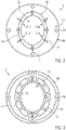
- the schematic figure 2 shows in plan view that the inner guide section 5a is preferably divided into partial circumferential segments 10.1 to 10.4. Recesses 11 and/or correspondingly flexible material are formed between these, for example, in order to enable an essentially independent elastic deformation of the partial circumferential segments 10.1 to 10.4 towards the base body 3. In addition, there can be recesses 12 on the upper side of the inner guide section 5a or other areas with weakened material.
- the rigidity of the inner guide section 5a can be reduced in a targeted manner in relation to the outer fastening section 5b in order to produce the elastic deformability of the inner guide section 5a towards the base body 3 .
- the inner guide portion 5a preferably comprises a downward, ie toward the base body, angled guide lip 13 for delimiting the central opening 5c.
- the guide lip 13 then has, for example, a profile that is chamfered on its upper side.
- the figure 2 also indicates that the central opening 5c for container bottoms 2a can be designed with non-round cross-sections, of course also for round cross-sections.
- the guide ring 5 can therefore be provided in a format-specific manner.
- the guide ring 5 is particularly suitable as an exchangeable part of a set for a specific container cross-section.
- a suitable set of identical guide rings 5 must then be kept available for each container cross-section to be treated and fastened to the base bodies 3 of the support plates 1 in the event of a format change.
- the attachment of the guide ring 5 is done for example by means in the figure 2 schematically indicated and accessible from above screw connections 14 on the base body 3.
- the figure 3 clarifies schematically in a view of the guide ring 5 from below that the inner guide section 5a can include different reinforcements 15 or similar material reinforcements and/or recesses 16 or similar material weaknesses in order to achieve the required elastic deformability of the inner guide section 5a towards the base body 3 and/or to provide a suitable centering effect.
- Such structures can be produced generatively, for example in the 3D printing process, in a particularly flexible manner and, if necessary, also with different layers of material on top of one another.
- SLS selective laser sintering
- FDM Fused Deposition Modeling
- jet fusion printing based on jet printing a mixture of liquids and printing powders.
- the guide ring 5 is characterized in particular by the fact that it combines at least two different functions in one piece, namely: a dimensionally stable attachment of the guide ring 5 to the base body 3; a form-elastic coaxial guidance of the container 2 and/or its centering with respect to the central axis 1a of the support plate 1; and/or lateral protection against intrusion by means of outer side wall areas 5d.
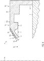
- the figure 4 shows a particularly favorable embodiment of an additively manufactured inner guide section 5a with at least two material layers of different colors.
- the inner guide section 5a comprises a wear indicator 17 in the form of a contact layer 19 specially colored up to a permissible wear depth 18 for the container 2, such as on the guide lip 13, on a support structure 20 colored differently.
- the contact layer 19 is produced in 3D printing up to the permissible wear depth 18 with a first color 19a and the support structure 20 is printed in a visually contrasting second color 20a.
- the contact layer 19 is then preferably 0.1 to 1 mm thick, corresponding to the respectively permissible wear depth 18.
- the inner guide section 5a consists, for example, of a thermoplastic material that is suitable for 3D printing. In operation, such materials are exposed to wear and tear when centering the container bottoms 2a. The progressive wear can then be detected visually in good time by means of a color change from the first color 19a to the second color 20a.
- the outer fastening section 5b comprises outer side walls 5d as protection against access, in particular to protect against bruises or the like when operating and/or maintaining the support plate 1.
- the outer side walls 5d are then preferably integrated in one piece into the fastening section 5b.
- the guide ring 5 is preferably made in a color that can be clearly identified visually from the outside, for example in the first or second color 19a, 20a, for assignment to a specific container format. This feature can advantageously be produced additively.
- the guide ring 5 can then be reliably assigned to a specific container format as part of a quick-change set, so that conversion work when changing the format is possible in an equally simple and error-free manner.
- the axially rigid attachment of the outer attachment section 5b and the integrated anti-tamper device make it easier to replace the guide ring 5 and clean it on the outside.
- a correspondingly low-gap surface is made possible by the fact that an axial elasticity of the guide ring 5 in the area of its central opening 5c is not achieved with separate components such as compression springs or the like, but by elastic deformability of the inner guide section 5a relative to the outer fastening section 5b.
- Additive manufacturing using 3D printing, enables the guide ring 3 and in particular its inner guide section 5a to be shaped in a cost-effective manner and flexibly adapted to different requirements.
- thermoplastics as well as composite materials can be used here, such as alumide, in order to achieve the required elastic deformability of the inner guide section 5a and the dimensional stability of the outer fastening section 5b in a one-piece construction.
- advantageous properties such as color coding of the guide ring 5 to match certain container formats and/or a wear indicator 17 in the form of a separately colored contact layer 19 for the container bottom 2a can be provided in a comparatively simple and just as flexibly adaptable manner.
Landscapes
- Engineering & Computer Science (AREA)
- Manufacturing & Machinery (AREA)
- Mechanical Engineering (AREA)
- Support Of The Bearing (AREA)
Description
- Die Erfindung betrifft einen Auflageteller gemäß Oberbegriff des Anspruchs 1, eine Behandlungsmaschine mit wenigstens einem Auflageteller und ein Herstellungsverfahren für den Auflageteller.
- Ein Auflageteller ist beispielsweise aus der
DE 20 2015 103853 U1 und derEP 2 746 176 A1 bekannt und dient vorzugsweise in Kombination mit einem Drehantrieb als Drehteller zum Positionieren von Behältern auf Behältertischen von Etikettiermaschinen und/oder Direktdruckmaschinen. Derartige Auflageteller sind dann beispielsweise mit individuellen Servomotoren ausgestattet und gleichmäßig entlang des Umfangs des Behältertisches angeordnet. - Der Auflageteller der
EP 2 746 176 A1 weist eine Grundplatte auf sowie eine darauf mittels Druckfedern elastisch abgestützte Auflageplatte für einen Behälterboden. Die Auflageplatte ist ferner von einem auf separaten Druckfedern stehenden Führungsring eingefasst. Dieser weist entlang seiner inneren Führungskante eine Fase auf und erlaubt ein Absetzen von Behältern auf der Auflageplatte auch bei Bodenquerschnitten, die aufgrund von Maßtoleranzen teilweise auch an der inneren Führungskante aufliegen. In diesem Fall wird der Führungsring vom Behälterboden gegen die Rückstellkraft der Druckfedern nach unten gedrückt, bis der Behälterboden auf der Auflageplatte steht. Dabei zentriert der Führungsring den Behälter auch bezüglich der Auflageplatte. - Nachteilig ist jedoch, dass für den Führungsring mehrere umfänglich verteilte Druckfedern und Führungsbolzen nötig sind. Zudem muss zwischen den Druckfedern ein seitlicher Eingriffsschutz separat montiert werden, beispielsweise in Form von Spritzgussteilen. Der gattungsgemäße Auflageteller ist daher in der Herstellung und Instandhaltung aufwändig. Zudem ist der Austausch des Führungsrings bei Formatwechseln vergleichsweise umständlich.
- Darüber hinaus, die
EP 2 746 176 A1 erwähnt einen Auflageteller gemäß dem Oberbegriff des Anspruchs 1 als Stand der Technik. - Es besteht daher der Bedarf für demgegenüber verbesserte Auflageteller.
- Die gestellte Aufgabe wird mit einem Auflageteller gemäß Anspruch 1 gelöst. Demnach dient dieser zum Positionieren von Behältern, insbesondere auf drehbaren Behältertischen. Der Auflageteller umfasst einen Grundkörper, eine darüber nach unten hin einfedemd gelagerte Auflageplatte für einen Behälter und einen die Auflageplatte einfassenden Führungsring mit einem inneren Führungsabschnitt zur umfänglichen Führung des Behälters und mit einem äußeren Befestigungsabschnitt zur starren Befestigung am
- Grundkörper. Erfindungsgemäß ist der innere Führungsabschnitt gegenüber dem äußeren Befestigungsabschnitt des Führungsrings zum Grundkörper hin elastisch verformbar.
- Durch die elastische Verformbarkeit des inneren Führungsabschnitts ist eine axial gefederte Lagerung des äußeren Befestigungsabschnitts entbehrlich. Stattdessen ist der äußere Befestigungsabschnitt und somit der gesamte Führungsring auf vergleichsweise einfache Weise starr auf dem Grundkörper befestigt. Es werden weniger Einzelteile benötigt. Entsprechend einfach ist auch ein Austausch des Führungsrings beispielsweise bei Formatwechseln, also zur Anpassung an Behälter mit einem anderen Bodenquerschnitt. Zudem lässt sich die Außenseite des Führungsrings mit weniger Spalten und anderen schwierig zu reinigenden Oberflächen ausbilden.
- Eine elastische Verformbarkeit des inneren Führungsabschnitts lässt sich insbesondere dadurch erzielen, dass dieser eine geringere Steifigkeit aufweist als der äußere Befestigungsabschnitt. Zu diesem Zweck umfasst der innere Führungsabschnitt beispielsweise Bereiche mit gezielter Materialschwächung und/oder Materialausnehmung.
- Vorzugsweise umfasst der innere Führungsabschnitt wenigstens drei teilumfängliche und getrennt voneinander elastisch verformbare Segmente. Besonders bevorzugt ist eine Unterteilung in vier bis acht teilumfängliche und getrennt voneinander elastisch verformbare Segmente. Dies erleichtert eine gleichmäßige und insbesondere zentrierende Verformung der Segmente zum Grundkörper hin. Durch die Segmentierung lässt sich die Materialspannung im inneren Führungsabschnitt bei der elastischen Verformung gezielt an den Querschnitt des Behälterbodens anpassen, beispielsweise für nichtrunde Querschnitte.
- Vorzugsweise umfasst der innere Führungsabschnitt wenigstens eine zum Grundkörper hin abgewinkelte Führungslippe. Die Führungslippe kann auf ihrer Oberseite eine umfänglich verlaufende Fase umfassen. Die Abwinklung der Führungslippe erleichtert eine Zentrierung des von dem inneren Führungsabschnitt geführten Behälters bezüglich der Mittelachse des Auflagetellers.
- Vorzugsweise ist der äußere Befestigungsabschnitt als oberer Anschlag für die Auflageplatte ausgebildet. Die Auflageplatte ist vorzugsweise mittels wenigstens einer Druckfeder auf dem Grundkörper abgestützt. Die wenigstens eine Druckfeder drückt die Auflageplatte dann axial vom Grundkörper weg und gegen den Führungsring. Dadurch lässt sich die unbelastete Ruheposition der Auflageplatte auf einem definierten Höhenniveau bezüglich des Grundkörpers exakt festlegen. Es ist jedoch auch möglich, dieses Höhenniveau ohne oberen Anschlag nur durch die Länge der unbelasteten (ohne aufliegenden Behälter) Druckfeder(n) vorzugeben. Vorzugsweise umfasst der äußere Befestigungsabschnitt äußere Seitenwandbereiche zum Eingriffsschutz. Der Eingriffsschutz ist dann vorzugsweise einstückig in den Führungsring integriert, könnte aber auch mittels Schnappverbindung oder dergleichen daran befestigt werden. Die äußeren Seitenwandbereiche dienen dann vorzugsweise auch der Abschirmung gegenüber Staub und/oder Flüssigkeiten.
- Vorzugsweise besteht wenigstens der innere Führungsabschnitt des Führungsrings aus einem generativ, im 3D-Druck, gefertigten Material. Der Führungsabschnitt besteht dann aus einem schichtweise aufgebauten Kunststoff oder Metall-Kunststoff-Verbund, wie beispielsweise Alumide. Dadurch lassen sich vergleichsweise komplexe Strukturen, wie beispielsweise Hinterschneidungen, Aussparungen, Versteifungen oder dergleichen herstellen, um innere Führungsabschnitte mit geeigneter Steifigkeit und Elastizität auszubilden und an vorgegebene Behälterquerschnitte anzupassen. Der innere Führungsabschnitt kann sich dann auf geeignete Weise elastisch verformen und den Behälterboden zentrieren.
- Besonders vorteilhaft ist eine generative Herstellung des gesamten Führungsrings im 3D-Druck aus wenigstens einem Kunststoff und/oder Metall-Kunststoff-Verbund wie oben beschrieben. Hierbei können der innere Führungsabschnitt und der äußere Befestigungsabschnitt auch aus unterschiedlichen 3D-Druckmaterialien bestehen.
- Vorzugsweise besteht wenigstens der innere Führungsabschnitt im Wesentlichen aus einem thermoplastischen Kunststoff und umfasst in einem Kontaktbereich mit den Behältern eine bis zu einer zulässigen Verschleißtiefe separat eingefärbte äußere Kontaktschicht. Eine derartige Kontaktschicht lässt sich vorteilhaft generativ, also im 3D-Druck, herstellen, indem die Kontaktschicht mit einer separaten Farbe auf eine Stützstruktur gedruckt wird.
- Das Erreichen der Verschleißtiefe lässt sich dann durch einen Farbwechsel an der verschlissenen Stelle visuell erkennen. Zu diesem Zweck ist die unter der Kontaktschicht liegende Stützstruktur mit einer davon abweichenden Farbe insbesondere generativ gefertigt. Vorzugsweise ist die äußere Kontaktschicht dann auf eine Tiefe von 0,1 bis 1 mm separat eingefärbt. Dadurch lässt sich ein Materialverschleiß besonders praktikabel überwachen.
- Vorzugsweise besteht wenigstens der Führungsabschnitts des Führungsrings aus einem zur Kennzeichnung der lichten Weite und/oder der Öffnungsform des Führungsrings eingefärbten Kunststoff.
- Vorzugsweise besteht der gesamte Führungsring zumindest auf seiner Außenseite aus einem entsprechend eingefärbten Kunststoff. Somit können bestimmte Führungsringe passend zu bestimmten Behälterformaten farblich gekennzeichnet und bei einem Formatwechsel einfach zugeordnet werden. Dadurch lässt sich eine fehlerhafte Ausstattung der Auflageteller mit unpassenden Führungsringen zuverlässig vermeiden.
- Vorzugsweise ist der Führungsring bei montierter Grundplatte auswechselbar und zudem Bestandteil einer formatspezifischen Garnitur identischer Führungsringe. Es sind vorzugsweise mehrere solche Garnituren passend zu unterschiedlichen Behälterquerschnitten vorhanden. Die Auflageteller lassen sich dann unproblematisch und schnell bei Formatwechseln umrüsten.
- Die gestellte Aufgabe wird ebenso mit einer Behandlungsmaschine für Behälter gemäß Anspruch 11 gelöst. Demnach umfasst diese einen insbesondere kontinuierlich drehbaren Behältertisch und eine Vielzahl daran vorzugsweise um sich selbst drehbar befestigter Auflageteller gemäß wenigstens einer der voranstehend beschriebenen Ausführungsformen.
- Vorzugsweise sind für die Behandlungsmaschine dann wenigstens zwei Garnituren formatspezifisch eingefärbter Führungsringe vorhanden. Dadurch kann die Behandlungsmaschine einfach und fehlerfrei an das zu behandelnde Behälterformat angepasst werden.
- Die gestellte Aufgabe wird ebenso mit einem Herstellungsverfahren für einen Auflageteller gemäß Anspruch 13 gelöst. Demnach wird wenigstens der Führungsabschnitt des Führungsrings gemäß wenigstens einer der voranstehend beschriebenen Ausführungsformen generativ gefertigt, mittels 3D-Druck. Der Führungsring lässt sich dann an unterschiedliche Behälterformate, beispielsweise auch nicht runde Behälterquerschnitte, vergleichsweise einfach und mit diesbezüglich optimierter Geometrie anpassen.
- Generative Fertigung erfolgt im Wesentlichen ohne formspeichernde Urformen, spanabhebende / trennende Werkzeuge oder dergleichen.
- Vorzugsweise wird dann wenigstens eine Außenseite des Führungsrings mit einer einem Behälterformat zugeordneten Druckfarbe im 3D-Druck gefertigt. Damit lässt sich der Führungsring bei Formatwechseln zuverlässig einem bestimmten Behälterformat zuordnen. Die korrekte Montage lässt sich ebenso einfach an der Behandlungsmaschine überprüfen.
- Vorzugsweise wird wenigstens eine im Arbeitsbetrieb mit dem Behälter in Kontakt kommende äußere Kontaktschicht des Führungsrings über eine zulässige Verschleißtiefe mit einer anderen Druckfarbe im 3D-Druck gefertigt als eine darunterliegende Stützstruktur des Führungsrings. Auf diese Weise lässt sich ein Verschleißindikator für den Führungsring bereitstellen. Der Verschleißindikator lässt sich im Arbeitsbetrieb vergleichsweise einfach visuell überwachen.
- Bevorzugte Ausführungsformen der Erfindung sind in den Zeichnungen dargestellt. Es zeigen:
- Figur 1
- einen schematischen Längsschnitt durch einen Auflageteller;
- Figur 2
- eine schematische Draufsicht auf den Auflageteller;
- Figur 3
- eine schematische Ansicht des Führungsrings von unten; und
- Figur 4
- einen schematischen Längsschnitt durch den inneren Führungsabschnitt.
- Wie die
Figur 1 erkennen lässt, umfasst der Auflageteller 1 für Behälter 2 einen Grundkörper 3 und darüber eine nach unten hin einfedernd gelagerte Auflageplatte 4 für den Behälter 2. Die Auflageplatte 4 ist von einem Führungsring 5 mit einem inneren Führungsabschnitt 5a und einem äußeren Befestigungsabschnitt 5b eingefasst. - Der innere Führungsabschnitt 5a begrenzt eine zentrale Öffnung 5c des Führungsrings 5 und führt den Behälterboden 2a umfänglich beim Absenken auf die / mit der Auflageplatte 4. Der innere Führungsabschnitt 5a zentriert den Behälter 2 bezüglich einer Mittelachse 1a des Auflagetellers 1. Die zentrale Öffnung 5c passt zu diesem Zweck hinsichtlich ihrer lichten Weite und Öffnungsform zum jeweiligen Querschnittformat des Behälters 2.
- Beim Abstellen des Behälters 2 auf dem Auflageteller 1 kann der Behälterboden 2a je nach Maßtoleranz und/oder Positionierungsgenauigkeit auf den inneren Führungsabschnitt 5a drücken und diesen dabei zur Grundplatte 3 hin (nach unten) elastisch verformen.
- Der äußere Befestigungsabschnitt 5b ist demgegenüber starr und bleibt beim Abstellen des Behälters 2 im Wesentlichen formstabil. Der äußere Befestigungsabschnitt 5b ist mit der Grundplatte 3 verschraubt oder anderweitig drehfest verbunden.
- Die Auflageplatte 4 sitzt auf Druckfedern 6 oder wenigstens einem dergleichen elastischen Element und ist somit zur Grundplatte 3 hin einfedernd gelagert. Der Führungsring 5 dient vorzugsweise als ein nach oben begrenzender Anschlag 7 für die Auflageplatte 4. Der Anschlag 7 legt die obere Stellung der unbelasteten Auflageplatte 4 gegen die Vorspannung der Druckfedern 6 fest.
- Alternativ dazu könnten Länge und Federkraft der Druckfedern 6 derart ausgelegt sein, dass die unbelastete Auflageplatte 4 auch ohne den Anschlag 7 die festgelegte obere Stellung einnimmt. Ebenso möglich wäre ein separater oberer Anschlag oder ein funktional entsprechendes Element für die Auflageplatte 4.
- Der Vollständigkeit halber dargestellt sind ferner eine Antriebswelle 8 zur beispielsweise servomotorischen Drehung des Auflagetellers 1 um sich selbst auf einem Behältertisch 9 einer Behandlungsmaschine, vorzugsweise einer Etikettiermaschine oder Direktdruckmaschine.
- Die schematische
Figur 2 zeigt in der Draufsicht, dass der innere Führungsabschnitt 5a vorzugsweise in teilumfängliche Segmente 10.1 bis 10.4 unterteilt ist. Zwischen diesen sind beispielsweise Ausnehmungen 11 und/oder entsprechend nachgiebiges Material ausgebildet, um eine im Wesentlichen voneinander unabhängige elastische Verformung der teilumfänglichen Segmente 10.1 bis 10.4 zum Grundkörper 3 hin zu ermöglichen. Zusätzlich können Ausnehmungen 12 auf der Oberseite des inneren Führungsabschnitts 5a oder anderweitige Bereiche mit Materialschwächung vorhanden sein. - Dadurch lässt sich die Steifigkeit des inneren Führungsabschnitts 5a gezielt gegenüber dem äußeren Befestigungsabschnitt 5b reduzieren, um die elastische Verformbarkeit des inneren Führungsabschnitts 5a zum Grundkörper 3 hin zu erzeugen.
- Wie die
Figuren 1 und2 erkennen lassen, umfasst der innere Führungsabschnitt 5a vorzugsweise eine nach unten, also zum Grundkörper hin, abgewinkelte Führungslippe 13 zur Umgrenzung der zentralen Öffnung 5c. Die Führungslippe 13 weist dann beispielsweise ein auf ihrer Oberseite gefastes Profil auf. - Die
Figur 2 deutet ferner an, dass die zentrale Öffnung 5c für Behälterböden 2a mit nichtrunden Querschnitten ausgebildet sein kann, selbstverständlich auch für runde Querschnitte. Der Führungsring 5 kann daher formatspezifisch bereitgestellt werden. - Der Führungsring 5 eignet sich in besonderem Maße als auswechselbarer Bestandteil einer Garnitur für einen bestimmten Behälterquerschnitt. Es ist dann für jeden zu behandelnden Behälterquerschnitt ein passender Satz identischer Führungsringe 5 vorzuhalten und bei einem Formatwechsel auf den Grundkörpern 3 der Auflageteller 1 zu befestigen.
- Die Befestigung des Führungsrings 5 erfolgt beispielsweise mittels in der
Figur 2 schematisch angedeuteter und von oben her zugänglicher Verschraubungen 14 am Grundkörper 3. - Die
Figur 3 verdeutlich schematisch in einer Ansicht des Führungsrings 5 von unten, dass das der innere Führungsabschnitt 5a unterschiedliche Versteifungen 15 oder dergleichen Materialverstärkungen und/oder Ausnehmungen 16 oder dergleichen Materialschwächungen umfassen kann, um die geforderte elastische Verformbarkeit des inneren Führungsabschnitts 5a zum Grundkörper 3 hin und/oder eine geeignete Zentrierwirkung bereitzustellen. - Derartige Strukturen lassen sich generativ, wie beispielsweise im 3D-Druckverfahren, besonders flexibel und gegebenenfalls auch mit unterschiedlichen Materialschichten übereinander fertigen.
- Dafür geeignete 3D-Druckverfahren sind beispielsweise: selektives Lasersintern (SLS); Schmelzschichten (Fused Deposition Modeling: FDM); und Jet-Fusion-Druck basierend auf dem Strahldrucken einer Mischung aus Flüssigkeiten und Druckpulvern.
- Der Führungsring 5 zeichnet sich insbesondere dadurch aus, dass er wenigstens zwei unterschiedliche Funktionen einstückig in sich vereint, nämlich: eine formstabile Befestigung des Führungsrings 5 am Grundkörper 3; eine formelastische koaxiale Führung des Behälters 2 und/oder dessen Zentrierung bezüglich der Mittelachse 1a des Auflagetellers 1; und/oder einen seitlichen Eingriffsschutz mittels äußerer Seitenwandbereiche 5d.
- Die
Figur 4 verdeutlicht eine besonders günstige Ausführungsform eines generativ gefertigten inneren Führungsabschnitts 5a mit wenigstens zwei Materialschichten unterschiedlicher Farbe. - Demnach umfasst der innere Führungsabschnitt 5a einen Verschleißindikator 17 in Form einer bis zu einer zulässigen Verschleißtiefe 18 speziell gefärbten Kontaktschicht 19 für den Behälter 2, wie beispielsweise an der Führungslippe 13, auf einer davon abweichend gefärbten Stützstruktur 20.
- Beispielsweise wird die Kontaktschicht 19 im 3D-Druck bis zur zulässigen Verschleißtiefe 18 mit einer ersten Farbe 19a hergestellt und die Stützstruktur 20 in einer visuell damit kontrastierenden zweiten Farbe 20a gedruckt. Die Kontaktschicht 19 ist dann vorzugsweise 0,1 bis 1 mm dick entsprechend der jeweils zulässigen Verschleißtiefe 18.
- Der innere Führungsabschnitt 5a besteht beispielsweise aus einem für den 3D-Druck geeigneten thermoplastischen Kunststoff. Im Arbeitsbetrieb sind derartige Materialien einem Verschleiß beim Zentrieren der Behälterböden 2a ausgesetzt. Der fortschreitende Verschleiß kann dann visuell anhand eines Farbwechsels von der ersten Farbe 19a zur zweiten Farbe 20a rechtzeitig erkannt werden.
- Wie die
Figuren 3 und4 andeuten, umfasst der äußere Befestigungsabschnitt 5b äußere Seitenwände 5d als Eingriffsschutz, insbesondere zum Schutz vor Quetschungen oder dergleichen bei der Bedienung und/oder Instandhaltung der Auflageteller 1. Die äußeren Seitenwände 5d sind dann vorzugsweise einstückig in den Befestigungsabschnitt 5b integriert. - Der Führungsring 5 ist vorzugsweise zur Zuordnung zu einem bestimmten Behälterformat in einer von außen visuell eindeutig identifizierbaren Farbe hergestellt, beispielsweise in der ersten oder zweiten Farbe 19a, 20a. Dieses Merkmal lässt sich vorteilhaft generativ fertigen.
- Der Führungsring 5 kann dann als Bestandteil einer schnellwechselbaren Garnitur einem bestimmten Behälterformat zuverlässig zugeordnet werden, so dass Umrüstarbeiten beim Formatwechsel gleichermaßen einfach und fehlerfrei möglich sind.
- Die axial starre Befestigung des äußeren Befestigungsabschnitts 5b und der integrierte Eingriffsschutz erleichtern den Austausch des Führungsrings 5 und dessen äußere Reinigung. Eine entsprechend spaltarme Oberfläche wird dadurch ermöglicht, dass eine axiale Elastizität des Führungsrings 5 im Bereich seiner zentralen Öffnung 5c nicht mit separaten Bauteilen, wie Druckfedern oder dergleichen, erzielt wird, sondern durch elastische Verformbarkeit des inneren Führungsabschnitts 5a gegenüber dem äußeren Befestigungsabschnitts 5b.
- Hierbei ermöglicht die generative Fertigung, mittels 3D-Druck, eine kostengünstige und an unterschiedliche Anforderungen flexibel anpassbare Formgebung des Führungsrings 3 und insbesondere seines inneren Führungsabschnitts 5a.
- Hierbei können sowohl unterschiedliche thermoplastische Kunststoffe als auch Verbundmaterialien zum Einsatz kommen, wie beispielsweise Alumide, um die geforderte elastische Verformbarkeit des inneren Führungsabschnitts 5a und die Formstabilität des äußeren Befestigungsabschnitts 5b in einstückiger Bauweise zu verwirklichen.
- Zudem lassen sich vorteilhafte Eigenschaften wie eine farbliche Kennzeichnung des Führungsrings 5 passend zu bestimmten Behälterformaten und/oder ein Verschleißindikator 17 in Form einer separat eingefärbten Kontaktschicht 19 für den Behälterboden 2a auf vergleichsweise einfache und ebenso flexibel anpassbare Weise bereitstellen.
- Zusätzliche Vorteile ergeben sich aus der generativen Fertigung für eine zeitnahe globale Ersatzteilversorgung und/oder Anpassung an zusätzliche Behälterformate vor Ort, da lediglich 3D-Drucker, Konstruktionsdaten und Rohmaterialien für die generative Fertigung nötig sind. Aufwändige Lagerhaltung und Logistik treten in den Hintergrund.
Claims (15)
- Auflageteller (1) zum Positionieren von Behältern (2) insbesondere auf drehbaren Behältertischen (9), umfassend: einen Grundkörper (3); eine darüber nach unten hin einfedemd gelagerte Auflageplatte (4) für einen Behälter (2); und einen die Auflageplatte (4) einfassenden Führungsring (5) mit einem inneren Führungsabschnitt (5a) zur umfänglichen Führung des Behälters (2) und mit einem äußeren Befestigungsabschnitt (5b) zur starren Befestigung am Grundkörper (3), dadurch gekennzeichnet, dass der innere Führungsabschnitt (5a) gegenüber dem äußeren Befestigungsabschnitt (5b) zum Grundkörper (3) hin elastisch verformbar ist.
- Auflageteller nach Anspruch 1, wobei der innere Führungsabschnitt (5a) wenigstens drei teilumfängliche und getrennt voneinander elastisch verformbare Segmente (10.1-10.4) umfasst.
- Auflageteller nach Anspruch 1 oder 2, wobei der innere Führungsabschnitt (5a) wenigstens eine zum Grundkörper (3) hin abgewinkelte Führungslippe (13) umfasst.
- Auflageteller nach einem der vorigen Ansprüche, wobei der äußere Befestigungsabschnitt (5b) als ein nach oben begrenzender Anschlag (7) für die Auflageplatte (4) ausgebildet ist.
- Auflageteller nach einem der vorigen Ansprüche, wobei der äußere Befestigungsabschnitt (5b) äußere Seitenwandbereiche (5d) als Eingriffsschutz umfasst.
- Auflageteller nach einem der vorigen Ansprüche, wobei wenigstens der innere Führungsabschnitt (5a) des Führungsrings (5) aus einem generativ, insbesondere im 3D-Druck, gefertigten Material besteht.
- Auflageteller nach einem der vorigen Ansprüche, wobei wenigstens der innere Führungsabschnitt (5a) im Wesentlichen aus einem thermoplastischen Kunststoff besteht und in einem Kontaktbereich mit den Behältern (2) eine bis zu einer zulässigen Verschleißtiefe (18) separat eingefärbte äußere Kontaktschicht (19) umfasst.
- Auflageteller nach Anspruch 7, wobei die äußere Kontaktschicht (19) auf eine Tiefe von 0,1 bis 1 mm eingefärbt ist.
- Auflageteller nach einem der vorigen Ansprüche, wobei wenigstens der Führungsabschnitt (5a) aus einem zur Kennzeichnung der lichten Weite und/oder der Öffnungsform des Führungsrings (5) eingefärbten Kunststoff besteht.
- Auflageteller nach wenigstens einem der vorigen Ansprüche, wobei der Führungsring (5) bei befestigter Grundplatte (3) auswechselbar und Bestandteil einer formatspezifischen Garnitur identischer Führungsringe (5) ist.
- Behandlungsmaschine für Behälter, umfassend einen insbesondere kontinuierlich drehbaren Behältertisch (9) und eine Vielzahl daran insbesondere um sich drehbar befestigter Auflageteller (1) nach wenigstens einem der vorigen Ansprüche.
- Behandlungsmaschine für Behälter nach Anspruch 11, ferner mit wenigstens zwei Garnituren formatspezifisch eingefärbter Führungsringe (5).
- Herstellungsverfahren für einen Auflageteller (1) nach wenigstens einem der vorigen Ansprüche 1 bis 10, wobei wenigstens der innere Führungsabschnitt (5a) des Führungsrings (5) generativ im 3D-Druck gefertigt wird.
- Herstellungsverfahren nach Anspruch 13, wobei wenigstens die Außenseite des Führungsrings (5) mit einer einem Behälterformat zugeordneten Druckfarbe im 3D-Druck gefertigt wird.
- Herstellungsverfahren nach Anspruch 13 oder 14, wobei wenigstens eine im Arbeitsbetrieb mit den Behältern (2) in Kontakt kommende äußere Kontaktschicht (19) des Führungsrings (5) bis zu einer zulässigen Verschleißtiefe (18) mit einer anderen Druckfarbe (19a) im 3D-Druck gefertigt wird als eine darunterliegende Stützstruktur (20) des Führungsrings (5).
Applications Claiming Priority (1)
| Application Number | Priority Date | Filing Date | Title |
|---|---|---|---|
| DE102017219542.8A DE102017219542A1 (de) | 2017-11-03 | 2017-11-03 | Auflageteller zum Positionieren von Behältern |
Publications (3)
| Publication Number | Publication Date |
|---|---|
| EP3489158A2 EP3489158A2 (de) | 2019-05-29 |
| EP3489158A3 EP3489158A3 (de) | 2019-11-06 |
| EP3489158B1 true EP3489158B1 (de) | 2022-10-26 |
Family
ID=63832305
Family Applications (1)
| Application Number | Title | Priority Date | Filing Date |
|---|---|---|---|
| EP18199557.2A Active EP3489158B1 (de) | 2017-11-03 | 2018-10-10 | Auflageteller zum positionieren von behältern |
Country Status (3)
| Country | Link |
|---|---|
| EP (1) | EP3489158B1 (de) |
| CN (1) | CN209973043U (de) |
| DE (1) | DE102017219542A1 (de) |
Families Citing this family (5)
| Publication number | Priority date | Publication date | Assignee | Title |
|---|---|---|---|---|
| DE202020103757U1 (de) | 2020-06-30 | 2021-10-04 | Krones Aktiengesellschaft | Behälterteller |
| DE102020134672A1 (de) * | 2020-12-22 | 2022-06-23 | Krones Aktiengesellschaft | Verschleißteil, Herstellungsverfahren und Vorrichtung zur Überwachung eines Verschleißzustands |
| CN112977906B (zh) * | 2021-03-25 | 2022-07-05 | 江西诺泰生物科技有限公司 | 一种生产用儿童营养米粉装罐设备 |
| CN113002909B (zh) * | 2021-04-12 | 2022-07-08 | 江西永叔府食品有限公司 | 一种腐乳空罐用外壁贴标的装置 |
| DE102023108745A1 (de) | 2023-04-05 | 2024-10-10 | Khs Gmbh | Andrückeinrichtung für eine Behälterbehandlungseinrichtung |
Citations (7)
| Publication number | Priority date | Publication date | Assignee | Title |
|---|---|---|---|---|
| WO1999052811A1 (en) | 1996-11-14 | 1999-10-21 | Kao Corporation | Article holding tool |
| JP2000327090A (ja) | 1999-05-18 | 2000-11-28 | Kao Corp | 物品の載置具 |
| US20020195745A1 (en) | 1999-05-14 | 2002-12-26 | Kao Corporation | Material holding implement |
| DE10319371A1 (de) | 2002-05-01 | 2003-11-13 | Kao Corp | Artikelhalter |
| EP2746176A1 (de) | 2012-12-19 | 2014-06-25 | Krones AG | Auflageteller mit Druckelementen |
| DE202015103853U1 (de) | 2015-07-22 | 2015-08-06 | Krones Ag | Behälterteller zur Aufnahme eines Behälters in einer Behälterbehandlungsmaschine |
| DE102014104480A1 (de) | 2014-03-31 | 2015-10-01 | Sig Technology Ag | Vorrichtung zur Veränderung der Strahlform von fließfähigen Produkten |
Family Cites Families (6)
| Publication number | Priority date | Publication date | Assignee | Title |
|---|---|---|---|---|
| DE3308489C2 (de) * | 1983-03-10 | 1986-07-03 | Krones Ag Hermann Kronseder Maschinenfabrik, 8402 Neutraubling | Zentriervorrichtung für aufrecht stehende Gefäße, insbesondere in Etikettiermaschinen |
| DE202014102157U1 (de) * | 2014-05-08 | 2015-08-11 | Krones Aktiengesellschaft | Auflageteller und Vorrichtung mit einer Mehrzahl solcher Auflageteller zur Aufnahme von Behältern |
| CN104192385B (zh) * | 2014-08-14 | 2016-06-22 | 青岛德隆科技有限公司 | 一种可在曲面容器上黏贴商标纸的专用全自动贴标机 |
| DE102015220141A1 (de) * | 2015-10-16 | 2017-04-20 | Krones Ag | Verfahren und Vorrichtung zum bodenseitigen Etikettieren von Behältern |
| DE202015106745U1 (de) * | 2015-12-11 | 2016-01-15 | Krones Ag | Etikettiervorrichtung umfassend einen Greiferzylinder mit einer Vielzahl von Greifern mit Greiferschwämmen |
| DE202017104731U1 (de) * | 2017-08-08 | 2017-08-17 | Krones Ag | Behältertransportvorrichtung zum stehenden Transport von Behältern |
-
2017
- 2017-11-03 DE DE102017219542.8A patent/DE102017219542A1/de active Pending
-
2018
- 2018-10-10 EP EP18199557.2A patent/EP3489158B1/de active Active
- 2018-11-01 CN CN201821792533.8U patent/CN209973043U/zh active Active
Patent Citations (8)
| Publication number | Priority date | Publication date | Assignee | Title |
|---|---|---|---|---|
| WO1999052811A1 (en) | 1996-11-14 | 1999-10-21 | Kao Corporation | Article holding tool |
| US20020195745A1 (en) | 1999-05-14 | 2002-12-26 | Kao Corporation | Material holding implement |
| JP2000327090A (ja) | 1999-05-18 | 2000-11-28 | Kao Corp | 物品の載置具 |
| DE10319371A1 (de) | 2002-05-01 | 2003-11-13 | Kao Corp | Artikelhalter |
| US20030217947A1 (en) | 2002-05-01 | 2003-11-27 | Kao Corporation | Article holder |
| EP2746176A1 (de) | 2012-12-19 | 2014-06-25 | Krones AG | Auflageteller mit Druckelementen |
| DE102014104480A1 (de) | 2014-03-31 | 2015-10-01 | Sig Technology Ag | Vorrichtung zur Veränderung der Strahlform von fließfähigen Produkten |
| DE202015103853U1 (de) | 2015-07-22 | 2015-08-06 | Krones Ag | Behälterteller zur Aufnahme eines Behälters in einer Behälterbehandlungsmaschine |
Also Published As
| Publication number | Publication date |
|---|---|
| DE102017219542A1 (de) | 2019-05-09 |
| CN209973043U (zh) | 2020-01-21 |
| EP3489158A2 (de) | 2019-05-29 |
| EP3489158A3 (de) | 2019-11-06 |
Similar Documents
| Publication | Publication Date | Title |
|---|---|---|
| EP3489158B1 (de) | Auflageteller zum positionieren von behältern | |
| DE19903084C2 (de) | Strangpreßkopf zum Extrusionsblasformen von Kunststoffbehältern | |
| DE19816327A1 (de) | Seilrolle | |
| DE69507330T2 (de) | Schutzbälge | |
| EP2099683B1 (de) | Auflageteller | |
| DE102010026607A1 (de) | Vorrichtung zum rotativen Stanzen von flachem mehrschichtigem Gut | |
| WO2012117114A1 (de) | Filterelement für die filtrierung eines fluids und daraus gebildete filtereinheit | |
| EP3056777B1 (de) | Behälterbehandlungsmaschine mit einem drehtellerdirektantrieb | |
| EP1961948B1 (de) | Filter, insbesondere Kraftstofffilter | |
| DE102019121824B4 (de) | Vorrichtung für einen Walzenkörper einer Rotationswalze und Verfahren zum Herstellen sowie Druckwalzenadapter und Druckwalze | |
| DE102007043584A1 (de) | Rotor für eine Rundlauf-Tablettenpresse | |
| WO2013020895A1 (de) | Verfahren zum herstellen eines maschinenelementes und maschinenelement, insbesondere wellenlager | |
| EP2707214B1 (de) | Rotor für eine rundläuferpresse umfassend ein codierelement für die bestückung mindestens eines kurventrägers des rotors und verfahren zum bestücken der kurventräger auf dem rotor | |
| DE102010049558A1 (de) | Pendelmasse für eine Fliehkraftpendeleinrichtung | |
| DE102019131923A1 (de) | Werkzeug zum Beschneiden von Fasermaterialien | |
| EP2332712A1 (de) | Einlegestempel sowie Verfahren zum Einlegen von Banderole- und Bodenlabe in eine Spritzgussform | |
| EP2359970B1 (de) | Werkzeugwagen für eine Plattenbearbeitungsanlage. | |
| DE202020103757U1 (de) | Behälterteller | |
| DE4104457C2 (de) | Vollreifen | |
| DE102019210809B4 (de) | Niederhalter für ein Tiefziehwerkzeug und Tiefziehwerkzeug | |
| DE102016222883A1 (de) | Spritzgussform zur Herstellung einer Kappe eines Federbeinlagers sowie Fe-derbeinlager | |
| EP0839740A1 (de) | Zellenradschleuse mit schnellwechselbarer Dichtungsanordnung | |
| WO2022100784A1 (de) | Kodierer eines radlagers | |
| EP3429946A1 (de) | Behälterbehandlungsanlage | |
| DE1294645B (de) | Formwerkzeug zum Herstellen von an einem gemeinsamen Tragkoerper unter Einschaltung von Zwischenraeumen angeformten Scheiben aus Kunststoff, wobei die Scheiben mit umfangsseitig vorgesehenen Ausformungen in Form von Steuerkurven, Steuernocken und/oder Zaehnen versehen sind |
Legal Events
| Date | Code | Title | Description |
|---|---|---|---|
| PUAI | Public reference made under article 153(3) epc to a published international application that has entered the european phase |
Free format text: ORIGINAL CODE: 0009012 |
|
| STAA | Information on the status of an ep patent application or granted ep patent |
Free format text: STATUS: THE APPLICATION HAS BEEN PUBLISHED |
|
| AK | Designated contracting states |
Kind code of ref document: A2 Designated state(s): AL AT BE BG CH CY CZ DE DK EE ES FI FR GB GR HR HU IE IS IT LI LT LU LV MC MK MT NL NO PL PT RO RS SE SI SK SM TR |
|
| AX | Request for extension of the european patent |
Extension state: BA ME |
|
| PUAL | Search report despatched |
Free format text: ORIGINAL CODE: 0009013 |
|
| AK | Designated contracting states |
Kind code of ref document: A3 Designated state(s): AL AT BE BG CH CY CZ DE DK EE ES FI FR GB GR HR HU IE IS IT LI LT LU LV MC MK MT NL NO PL PT RO RS SE SI SK SM TR |
|
| AX | Request for extension of the european patent |
Extension state: BA ME |
|
| RIC1 | Information provided on ipc code assigned before grant |
Ipc: B65C 9/04 20060101AFI20191001BHEP Ipc: B65B 43/60 20060101ALI20191001BHEP Ipc: B41J 3/407 20060101ALI20191001BHEP Ipc: B65C 9/06 20060101ALI20191001BHEP |
|
| STAA | Information on the status of an ep patent application or granted ep patent |
Free format text: STATUS: REQUEST FOR EXAMINATION WAS MADE |
|
| 17P | Request for examination filed |
Effective date: 20200427 |
|
| RBV | Designated contracting states (corrected) |
Designated state(s): AL AT BE BG CH CY CZ DE DK EE ES FI FR GB GR HR HU IE IS IT LI LT LU LV MC MK MT NL NO PL PT RO RS SE SI SK SM TR |
|
| GRAP | Despatch of communication of intention to grant a patent |
Free format text: ORIGINAL CODE: EPIDOSNIGR1 |
|
| STAA | Information on the status of an ep patent application or granted ep patent |
Free format text: STATUS: GRANT OF PATENT IS INTENDED |
|
| RIC1 | Information provided on ipc code assigned before grant |
Ipc: B65B 43/60 20060101ALI20220511BHEP Ipc: B41J 3/407 20060101ALI20220511BHEP Ipc: B65C 9/06 20060101ALI20220511BHEP Ipc: B65C 9/04 20060101AFI20220511BHEP |
|
| INTG | Intention to grant announced |
Effective date: 20220527 |
|
| GRAS | Grant fee paid |
Free format text: ORIGINAL CODE: EPIDOSNIGR3 |
|
| GRAA | (expected) grant |
Free format text: ORIGINAL CODE: 0009210 |
|
| STAA | Information on the status of an ep patent application or granted ep patent |
Free format text: STATUS: THE PATENT HAS BEEN GRANTED |
|
| AK | Designated contracting states |
Kind code of ref document: B1 Designated state(s): AL AT BE BG CH CY CZ DE DK EE ES FI FR GB GR HR HU IE IS IT LI LT LU LV MC MK MT NL NO PL PT RO RS SE SI SK SM TR |
|
| REG | Reference to a national code |
Ref country code: GB Ref legal event code: FG4D Free format text: NOT ENGLISH |
|
| REG | Reference to a national code |
Ref country code: CH Ref legal event code: EP |
|
| REG | Reference to a national code |
Ref country code: AT Ref legal event code: REF Ref document number: 1526896 Country of ref document: AT Kind code of ref document: T Effective date: 20221115 |
|
| REG | Reference to a national code |
Ref country code: DE Ref legal event code: R096 Ref document number: 502018010905 Country of ref document: DE |
|
| REG | Reference to a national code |
Ref country code: IE Ref legal event code: FG4D Free format text: LANGUAGE OF EP DOCUMENT: GERMAN |
|
| REG | Reference to a national code |
Ref country code: LT Ref legal event code: MG9D |
|
| REG | Reference to a national code |
Ref country code: NL Ref legal event code: MP Effective date: 20221026 |
|
| PG25 | Lapsed in a contracting state [announced via postgrant information from national office to epo] |
Ref country code: NL Free format text: LAPSE BECAUSE OF FAILURE TO SUBMIT A TRANSLATION OF THE DESCRIPTION OR TO PAY THE FEE WITHIN THE PRESCRIBED TIME-LIMIT Effective date: 20221026 |
|
| PG25 | Lapsed in a contracting state [announced via postgrant information from national office to epo] |
Ref country code: SE Free format text: LAPSE BECAUSE OF FAILURE TO SUBMIT A TRANSLATION OF THE DESCRIPTION OR TO PAY THE FEE WITHIN THE PRESCRIBED TIME-LIMIT Effective date: 20221026 Ref country code: PT Free format text: LAPSE BECAUSE OF FAILURE TO SUBMIT A TRANSLATION OF THE DESCRIPTION OR TO PAY THE FEE WITHIN THE PRESCRIBED TIME-LIMIT Effective date: 20230227 Ref country code: NO Free format text: LAPSE BECAUSE OF FAILURE TO SUBMIT A TRANSLATION OF THE DESCRIPTION OR TO PAY THE FEE WITHIN THE PRESCRIBED TIME-LIMIT Effective date: 20230126 Ref country code: LT Free format text: LAPSE BECAUSE OF FAILURE TO SUBMIT A TRANSLATION OF THE DESCRIPTION OR TO PAY THE FEE WITHIN THE PRESCRIBED TIME-LIMIT Effective date: 20221026 Ref country code: FI Free format text: LAPSE BECAUSE OF FAILURE TO SUBMIT A TRANSLATION OF THE DESCRIPTION OR TO PAY THE FEE WITHIN THE PRESCRIBED TIME-LIMIT Effective date: 20221026 Ref country code: ES Free format text: LAPSE BECAUSE OF FAILURE TO SUBMIT A TRANSLATION OF THE DESCRIPTION OR TO PAY THE FEE WITHIN THE PRESCRIBED TIME-LIMIT Effective date: 20221026 |
|
| PG25 | Lapsed in a contracting state [announced via postgrant information from national office to epo] |
Ref country code: RS Free format text: LAPSE BECAUSE OF FAILURE TO SUBMIT A TRANSLATION OF THE DESCRIPTION OR TO PAY THE FEE WITHIN THE PRESCRIBED TIME-LIMIT Effective date: 20221026 Ref country code: PL Free format text: LAPSE BECAUSE OF FAILURE TO SUBMIT A TRANSLATION OF THE DESCRIPTION OR TO PAY THE FEE WITHIN THE PRESCRIBED TIME-LIMIT Effective date: 20221026 Ref country code: LV Free format text: LAPSE BECAUSE OF FAILURE TO SUBMIT A TRANSLATION OF THE DESCRIPTION OR TO PAY THE FEE WITHIN THE PRESCRIBED TIME-LIMIT Effective date: 20221026 Ref country code: IS Free format text: LAPSE BECAUSE OF FAILURE TO SUBMIT A TRANSLATION OF THE DESCRIPTION OR TO PAY THE FEE WITHIN THE PRESCRIBED TIME-LIMIT Effective date: 20230226 Ref country code: HR Free format text: LAPSE BECAUSE OF FAILURE TO SUBMIT A TRANSLATION OF THE DESCRIPTION OR TO PAY THE FEE WITHIN THE PRESCRIBED TIME-LIMIT Effective date: 20221026 Ref country code: GR Free format text: LAPSE BECAUSE OF FAILURE TO SUBMIT A TRANSLATION OF THE DESCRIPTION OR TO PAY THE FEE WITHIN THE PRESCRIBED TIME-LIMIT Effective date: 20230127 |
|
| P01 | Opt-out of the competence of the unified patent court (upc) registered |
Effective date: 20230523 |
|
| REG | Reference to a national code |
Ref country code: DE Ref legal event code: R026 Ref document number: 502018010905 Country of ref document: DE |
|
| PLBI | Opposition filed |
Free format text: ORIGINAL CODE: 0009260 |
|
| PG25 | Lapsed in a contracting state [announced via postgrant information from national office to epo] |
Ref country code: SM Free format text: LAPSE BECAUSE OF FAILURE TO SUBMIT A TRANSLATION OF THE DESCRIPTION OR TO PAY THE FEE WITHIN THE PRESCRIBED TIME-LIMIT Effective date: 20221026 Ref country code: RO Free format text: LAPSE BECAUSE OF FAILURE TO SUBMIT A TRANSLATION OF THE DESCRIPTION OR TO PAY THE FEE WITHIN THE PRESCRIBED TIME-LIMIT Effective date: 20221026 Ref country code: EE Free format text: LAPSE BECAUSE OF FAILURE TO SUBMIT A TRANSLATION OF THE DESCRIPTION OR TO PAY THE FEE WITHIN THE PRESCRIBED TIME-LIMIT Effective date: 20221026 Ref country code: DK Free format text: LAPSE BECAUSE OF FAILURE TO SUBMIT A TRANSLATION OF THE DESCRIPTION OR TO PAY THE FEE WITHIN THE PRESCRIBED TIME-LIMIT Effective date: 20221026 Ref country code: CZ Free format text: LAPSE BECAUSE OF FAILURE TO SUBMIT A TRANSLATION OF THE DESCRIPTION OR TO PAY THE FEE WITHIN THE PRESCRIBED TIME-LIMIT Effective date: 20221026 |
|
| 26 | Opposition filed |
Opponent name: KHS GMBH Effective date: 20230628 |
|
| PLAX | Notice of opposition and request to file observation + time limit sent |
Free format text: ORIGINAL CODE: EPIDOSNOBS2 |
|
| PG25 | Lapsed in a contracting state [announced via postgrant information from national office to epo] |
Ref country code: SK Free format text: LAPSE BECAUSE OF FAILURE TO SUBMIT A TRANSLATION OF THE DESCRIPTION OR TO PAY THE FEE WITHIN THE PRESCRIBED TIME-LIMIT Effective date: 20221026 Ref country code: AL Free format text: LAPSE BECAUSE OF FAILURE TO SUBMIT A TRANSLATION OF THE DESCRIPTION OR TO PAY THE FEE WITHIN THE PRESCRIBED TIME-LIMIT Effective date: 20221026 |
|
| PG25 | Lapsed in a contracting state [announced via postgrant information from national office to epo] |
Ref country code: SI Free format text: LAPSE BECAUSE OF FAILURE TO SUBMIT A TRANSLATION OF THE DESCRIPTION OR TO PAY THE FEE WITHIN THE PRESCRIBED TIME-LIMIT Effective date: 20221026 |
|
| PLBB | Reply of patent proprietor to notice(s) of opposition received |
Free format text: ORIGINAL CODE: EPIDOSNOBS3 |
|
| PG25 | Lapsed in a contracting state [announced via postgrant information from national office to epo] |
Ref country code: MC Free format text: LAPSE BECAUSE OF FAILURE TO SUBMIT A TRANSLATION OF THE DESCRIPTION OR TO PAY THE FEE WITHIN THE PRESCRIBED TIME-LIMIT Effective date: 20221026 |
|
| REG | Reference to a national code |
Ref country code: CH Ref legal event code: PL |
|
| REG | Reference to a national code |
Ref country code: BE Ref legal event code: MM Effective date: 20231031 |
|
| PG25 | Lapsed in a contracting state [announced via postgrant information from national office to epo] |
Ref country code: LU Free format text: LAPSE BECAUSE OF NON-PAYMENT OF DUE FEES Effective date: 20231010 |
|
| GBPC | Gb: european patent ceased through non-payment of renewal fee |
Effective date: 20231010 |
|
| PG25 | Lapsed in a contracting state [announced via postgrant information from national office to epo] |
Ref country code: LU Free format text: LAPSE BECAUSE OF NON-PAYMENT OF DUE FEES Effective date: 20231010 |
|
| PG25 | Lapsed in a contracting state [announced via postgrant information from national office to epo] |
Ref country code: GB Free format text: LAPSE BECAUSE OF NON-PAYMENT OF DUE FEES Effective date: 20231010 |
|
| PG25 | Lapsed in a contracting state [announced via postgrant information from national office to epo] |
Ref country code: CH Free format text: LAPSE BECAUSE OF NON-PAYMENT OF DUE FEES Effective date: 20231031 |
|
| PG25 | Lapsed in a contracting state [announced via postgrant information from national office to epo] |
Ref country code: GB Free format text: LAPSE BECAUSE OF NON-PAYMENT OF DUE FEES Effective date: 20231010 Ref country code: CH Free format text: LAPSE BECAUSE OF NON-PAYMENT OF DUE FEES Effective date: 20231031 |
|
| PG25 | Lapsed in a contracting state [announced via postgrant information from national office to epo] |
Ref country code: BE Free format text: LAPSE BECAUSE OF NON-PAYMENT OF DUE FEES Effective date: 20231031 |
|
| PG25 | Lapsed in a contracting state [announced via postgrant information from national office to epo] |
Ref country code: IE Free format text: LAPSE BECAUSE OF NON-PAYMENT OF DUE FEES Effective date: 20231010 |
|
| PG25 | Lapsed in a contracting state [announced via postgrant information from national office to epo] |
Ref country code: IE Free format text: LAPSE BECAUSE OF NON-PAYMENT OF DUE FEES Effective date: 20231010 |
|
| PG25 | Lapsed in a contracting state [announced via postgrant information from national office to epo] |
Ref country code: BG Free format text: LAPSE BECAUSE OF FAILURE TO SUBMIT A TRANSLATION OF THE DESCRIPTION OR TO PAY THE FEE WITHIN THE PRESCRIBED TIME-LIMIT Effective date: 20221026 |
|
| PG25 | Lapsed in a contracting state [announced via postgrant information from national office to epo] |
Ref country code: BG Free format text: LAPSE BECAUSE OF FAILURE TO SUBMIT A TRANSLATION OF THE DESCRIPTION OR TO PAY THE FEE WITHIN THE PRESCRIBED TIME-LIMIT Effective date: 20221026 |
|
| REG | Reference to a national code |
Ref country code: AT Ref legal event code: MM01 Ref document number: 1526896 Country of ref document: AT Kind code of ref document: T Effective date: 20231010 |
|
| PLAB | Opposition data, opponent's data or that of the opponent's representative modified |
Free format text: ORIGINAL CODE: 0009299OPPO |
|
| PLAB | Opposition data, opponent's data or that of the opponent's representative modified |
Free format text: ORIGINAL CODE: 0009299OPPO |
|
| R26 | Opposition filed (corrected) |
Opponent name: KHS GMBH Effective date: 20230628 |
|
| PG25 | Lapsed in a contracting state [announced via postgrant information from national office to epo] |
Ref country code: AT Free format text: LAPSE BECAUSE OF NON-PAYMENT OF DUE FEES Effective date: 20231010 |
|
| PG25 | Lapsed in a contracting state [announced via postgrant information from national office to epo] |
Ref country code: AT Free format text: LAPSE BECAUSE OF NON-PAYMENT OF DUE FEES Effective date: 20231010 |
|
| R26 | Opposition filed (corrected) |
Opponent name: KHS GMBH Effective date: 20230628 |
|
| PG25 | Lapsed in a contracting state [announced via postgrant information from national office to epo] |
Ref country code: CY Free format text: LAPSE BECAUSE OF FAILURE TO SUBMIT A TRANSLATION OF THE DESCRIPTION OR TO PAY THE FEE WITHIN THE PRESCRIBED TIME-LIMIT; INVALID AB INITIO Effective date: 20181010 |
|
| PG25 | Lapsed in a contracting state [announced via postgrant information from national office to epo] |
Ref country code: HU Free format text: LAPSE BECAUSE OF FAILURE TO SUBMIT A TRANSLATION OF THE DESCRIPTION OR TO PAY THE FEE WITHIN THE PRESCRIBED TIME-LIMIT; INVALID AB INITIO Effective date: 20181010 |
|
| PGFP | Annual fee paid to national office [announced via postgrant information from national office to epo] |
Ref country code: IT Payment date: 20250922 Year of fee payment: 8 |
|
| PGFP | Annual fee paid to national office [announced via postgrant information from national office to epo] |
Ref country code: FR Payment date: 20250908 Year of fee payment: 8 |
|
| PG25 | Lapsed in a contracting state [announced via postgrant information from national office to epo] |
Ref country code: TR Free format text: LAPSE BECAUSE OF FAILURE TO SUBMIT A TRANSLATION OF THE DESCRIPTION OR TO PAY THE FEE WITHIN THE PRESCRIBED TIME-LIMIT Effective date: 20221026 |
|
| PGFP | Annual fee paid to national office [announced via postgrant information from national office to epo] |
Ref country code: DE Payment date: 20250902 Year of fee payment: 8 |