EP3489064B1 - Selbstanpassender verbinder - Google Patents
Selbstanpassender verbinder Download PDFInfo
- Publication number
- EP3489064B1 EP3489064B1 EP18201339.1A EP18201339A EP3489064B1 EP 3489064 B1 EP3489064 B1 EP 3489064B1 EP 18201339 A EP18201339 A EP 18201339A EP 3489064 B1 EP3489064 B1 EP 3489064B1
- Authority
- EP
- European Patent Office
- Prior art keywords
- fuel tank
- self
- tank wall
- accessory component
- wall
- Prior art date
- Legal status (The legal status is an assumption and is not a legal conclusion. Google has not performed a legal analysis and makes no representation as to the accuracy of the status listed.)
- Active
Links
Images


Classifications
-
- B—PERFORMING OPERATIONS; TRANSPORTING
- B65—CONVEYING; PACKING; STORING; HANDLING THIN OR FILAMENTARY MATERIAL
- B65D—CONTAINERS FOR STORAGE OR TRANSPORT OF ARTICLES OR MATERIALS, e.g. BAGS, BARRELS, BOTTLES, BOXES, CANS, CARTONS, CRATES, DRUMS, JARS, TANKS, HOPPERS, FORWARDING CONTAINERS; ACCESSORIES, CLOSURES, OR FITTINGS THEREFOR; PACKAGING ELEMENTS; PACKAGES
- B65D88/00—Large containers
- B65D88/02—Large containers rigid
- B65D88/12—Large containers rigid specially adapted for transport
-
- B—PERFORMING OPERATIONS; TRANSPORTING
- B60—VEHICLES IN GENERAL
- B60K—ARRANGEMENT OR MOUNTING OF PROPULSION UNITS OR OF TRANSMISSIONS IN VEHICLES; ARRANGEMENT OR MOUNTING OF PLURAL DIVERSE PRIME-MOVERS IN VEHICLES; AUXILIARY DRIVES FOR VEHICLES; INSTRUMENTATION OR DASHBOARDS FOR VEHICLES; ARRANGEMENTS IN CONNECTION WITH COOLING, AIR INTAKE, GAS EXHAUST OR FUEL SUPPLY OF PROPULSION UNITS IN VEHICLES
- B60K15/00—Arrangement in connection with fuel supply of combustion engines or other fuel consuming energy converters, e.g. fuel cells; Mounting or construction of fuel tanks
- B60K15/03—Fuel tanks
- B60K15/063—Arrangement of tanks
- B60K15/067—Mounting of tanks
-
- B—PERFORMING OPERATIONS; TRANSPORTING
- B60—VEHICLES IN GENERAL
- B60K—ARRANGEMENT OR MOUNTING OF PROPULSION UNITS OR OF TRANSMISSIONS IN VEHICLES; ARRANGEMENT OR MOUNTING OF PLURAL DIVERSE PRIME-MOVERS IN VEHICLES; AUXILIARY DRIVES FOR VEHICLES; INSTRUMENTATION OR DASHBOARDS FOR VEHICLES; ARRANGEMENTS IN CONNECTION WITH COOLING, AIR INTAKE, GAS EXHAUST OR FUEL SUPPLY OF PROPULSION UNITS IN VEHICLES
- B60K15/00—Arrangement in connection with fuel supply of combustion engines or other fuel consuming energy converters, e.g. fuel cells; Mounting or construction of fuel tanks
- B60K15/03—Fuel tanks
-
- F—MECHANICAL ENGINEERING; LIGHTING; HEATING; WEAPONS; BLASTING
- F16—ENGINEERING ELEMENTS AND UNITS; GENERAL MEASURES FOR PRODUCING AND MAINTAINING EFFECTIVE FUNCTIONING OF MACHINES OR INSTALLATIONS; THERMAL INSULATION IN GENERAL
- F16F—SPRINGS; SHOCK-ABSORBERS; MEANS FOR DAMPING VIBRATION
- F16F1/00—Springs
- F16F1/02—Springs made of steel or other material having low internal friction; Wound, torsion, leaf, cup, ring or the like springs, the material of the spring not being relevant
- F16F1/18—Leaf springs
-
- B—PERFORMING OPERATIONS; TRANSPORTING
- B60—VEHICLES IN GENERAL
- B60K—ARRANGEMENT OR MOUNTING OF PROPULSION UNITS OR OF TRANSMISSIONS IN VEHICLES; ARRANGEMENT OR MOUNTING OF PLURAL DIVERSE PRIME-MOVERS IN VEHICLES; AUXILIARY DRIVES FOR VEHICLES; INSTRUMENTATION OR DASHBOARDS FOR VEHICLES; ARRANGEMENTS IN CONNECTION WITH COOLING, AIR INTAKE, GAS EXHAUST OR FUEL SUPPLY OF PROPULSION UNITS IN VEHICLES
- B60K15/00—Arrangement in connection with fuel supply of combustion engines or other fuel consuming energy converters, e.g. fuel cells; Mounting or construction of fuel tanks
- B60K15/03—Fuel tanks
- B60K2015/03111—Swirl pots
-
- B—PERFORMING OPERATIONS; TRANSPORTING
- B60—VEHICLES IN GENERAL
- B60K—ARRANGEMENT OR MOUNTING OF PROPULSION UNITS OR OF TRANSMISSIONS IN VEHICLES; ARRANGEMENT OR MOUNTING OF PLURAL DIVERSE PRIME-MOVERS IN VEHICLES; AUXILIARY DRIVES FOR VEHICLES; INSTRUMENTATION OR DASHBOARDS FOR VEHICLES; ARRANGEMENTS IN CONNECTION WITH COOLING, AIR INTAKE, GAS EXHAUST OR FUEL SUPPLY OF PROPULSION UNITS IN VEHICLES
- B60K15/00—Arrangement in connection with fuel supply of combustion engines or other fuel consuming energy converters, e.g. fuel cells; Mounting or construction of fuel tanks
- B60K15/03—Fuel tanks
- B60K2015/03328—Arrangements or special measures related to fuel tanks or fuel handling
- B60K2015/03453—Arrangements or special measures related to fuel tanks or fuel handling for fixing or mounting parts of the fuel tank together
-
- B—PERFORMING OPERATIONS; TRANSPORTING
- B60—VEHICLES IN GENERAL
- B60K—ARRANGEMENT OR MOUNTING OF PROPULSION UNITS OR OF TRANSMISSIONS IN VEHICLES; ARRANGEMENT OR MOUNTING OF PLURAL DIVERSE PRIME-MOVERS IN VEHICLES; AUXILIARY DRIVES FOR VEHICLES; INSTRUMENTATION OR DASHBOARDS FOR VEHICLES; ARRANGEMENTS IN CONNECTION WITH COOLING, AIR INTAKE, GAS EXHAUST OR FUEL SUPPLY OF PROPULSION UNITS IN VEHICLES
- B60K15/00—Arrangement in connection with fuel supply of combustion engines or other fuel consuming energy converters, e.g. fuel cells; Mounting or construction of fuel tanks
- B60K15/03—Fuel tanks
- B60K2015/03328—Arrangements or special measures related to fuel tanks or fuel handling
- B60K2015/03453—Arrangements or special measures related to fuel tanks or fuel handling for fixing or mounting parts of the fuel tank together
- B60K2015/0346—Arrangements or special measures related to fuel tanks or fuel handling for fixing or mounting parts of the fuel tank together by welding
-
- B—PERFORMING OPERATIONS; TRANSPORTING
- B60—VEHICLES IN GENERAL
- B60K—ARRANGEMENT OR MOUNTING OF PROPULSION UNITS OR OF TRANSMISSIONS IN VEHICLES; ARRANGEMENT OR MOUNTING OF PLURAL DIVERSE PRIME-MOVERS IN VEHICLES; AUXILIARY DRIVES FOR VEHICLES; INSTRUMENTATION OR DASHBOARDS FOR VEHICLES; ARRANGEMENTS IN CONNECTION WITH COOLING, AIR INTAKE, GAS EXHAUST OR FUEL SUPPLY OF PROPULSION UNITS IN VEHICLES
- B60K15/00—Arrangement in connection with fuel supply of combustion engines or other fuel consuming energy converters, e.g. fuel cells; Mounting or construction of fuel tanks
- B60K15/03—Fuel tanks
- B60K2015/03328—Arrangements or special measures related to fuel tanks or fuel handling
- B60K2015/03453—Arrangements or special measures related to fuel tanks or fuel handling for fixing or mounting parts of the fuel tank together
- B60K2015/03467—Arrangements or special measures related to fuel tanks or fuel handling for fixing or mounting parts of the fuel tank together by clip or snap fit fittings
-
- B—PERFORMING OPERATIONS; TRANSPORTING
- B60—VEHICLES IN GENERAL
- B60Y—INDEXING SCHEME RELATING TO ASPECTS CROSS-CUTTING VEHICLE TECHNOLOGY
- B60Y2410/00—Constructional features of vehicle sub-units
- B60Y2410/10—Housings
-
- B—PERFORMING OPERATIONS; TRANSPORTING
- B60—VEHICLES IN GENERAL
- B60Y—INDEXING SCHEME RELATING TO ASPECTS CROSS-CUTTING VEHICLE TECHNOLOGY
- B60Y2410/00—Constructional features of vehicle sub-units
- B60Y2410/113—Mount clips, snap-fit, e.g. quick fit with elastic members
-
- Y—GENERAL TAGGING OF NEW TECHNOLOGICAL DEVELOPMENTS; GENERAL TAGGING OF CROSS-SECTIONAL TECHNOLOGIES SPANNING OVER SEVERAL SECTIONS OF THE IPC; TECHNICAL SUBJECTS COVERED BY FORMER USPC CROSS-REFERENCE ART COLLECTIONS [XRACs] AND DIGESTS
- Y10—TECHNICAL SUBJECTS COVERED BY FORMER USPC
- Y10T—TECHNICAL SUBJECTS COVERED BY FORMER US CLASSIFICATION
- Y10T403/00—Joints and connections
- Y10T403/45—Flexibly connected rigid members
Definitions
- the present disclosure relates generally to liquid receptacles and connectors that may be used to attach accessory components to those receptacles.
- Liquid receptacles may be used by a variety of industries. For example, the automotive industry may rely on a vehicle-mounted fuel tank to store fuel. That fuel may be consumed by an engine or other fuel-consuming device to generate power for operating the vehicle. To help monitor the fuel stored in the fuel tank and deliver it to the engine (or other device), as well as perform any other appropriate functions, various fuel tank accessory components may be carried by the fuel tank. These components may be attached to, or otherwise held in place by, a wall of the fuel tank.
- FR 2 918 595 A1 which is considered to be the closest prior art, describes a method for fastening an accessory to a plastic fuel tank, where the accessory is attached to a tank wall by means of a rivet formed from material of the tank wall.
- the invention proposes a liquid receptacle according to claim 1. Further optional features are described in the dependent claims 2-5.
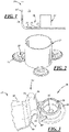
- FIG. 1 is a generalized schematic illustration of a liquid receptacle 10 and an accessory component 12 carried by the receptacle 10.
- the liquid receptacle 10 may be a fuel tank for an automotive vehicle-in which case the accessory component is a fuel tank accessory component-or it may be some other specific type of liquid receptacle. If the liquid receptacle 10 is a fuel tank, as will be described from this point forward, it generally includes a fuel tank wall 14 that defines an interior space 16 for holding fuel. And the number of fuel tank accessory components 12 that may be carried by the fuel tank 10 are numerous.
- a fuel pump module disposed inside the fuel tank 10 for pumping fuel out of the tank 10
- a baffle located inside the fuel tank 10 for managing fuel slosh, fuel or vapor conduits, vent valves, and vapor canisters, to name but a few such components.
- These various components may be made from any suitable plastic or metal material.
- the fuel tank wall 14 may have any desirable composition.
- a fuel tank wall 14 is a plastic structure that is designed to minimize fuel vapor permeation through the wall 14.
- the plastic structure may include one or more layers of high-density polyethylene (HDPE), at least one fuel vapor barrier layer such as, for example, ethylene vinyl alcohol (EVOH), and a binder layer that joins the HDPE layer and the fuel barrier layer.
- HDPE high-density polyethylene
- EVOH ethylene vinyl alcohol
- a binder layer that joins the HDPE layer and the fuel barrier layer.
- the fuel tank wall 14 moreover, may have a thickness that typically-but does not have to-ranges from about 2 mm to about 7 mm.
- the fuel tank wall 14 may be fabricated into its final shape by any suitable tank-forming procedure including blow-molding.
- the fuel tank accessory component 12 is attached to the fuel tank wall 14 by a self-adjusting connector 18.
- the self-adjusting connector 18 is designed to autonomously accommodate applied loads that may develop during manufacture and/or use of the fuel tank 10 and which may affect the attachment of the fuel tank accessory component 12 to the fuel tank wall 14. These applied loads can be the type that a rigid connector would have more difficulty tolerating and, as a result, might cause one or more of the tank wall 14, the rigid connector, and the fuel tank accessory component 12 to unduly fatigue, break, or otherwise suffer some type of stress-related malfunction.
- the self-adjusting connector 18 includes a mounting portion 20, a flange portion 22, and a load-accommodating portion 24 situated between the mounting portion 20 and the flange portion 22.
- the mounting portion 20 includes a foot (and may hereafter be called a "foot portion") adapted for attachment to the fuel tank wall 14 at an attachment site 26.
- a foot and may hereafter be called a "foot portion" adapted for attachment to the fuel tank wall 14 at an attachment site 26.
- the claimed invention is limited to a particular type of attachment. According to a more general approach, which is not claimed, any known type of attachment mechanism may be employed to facilitate such attachment.
- the foot portion 20 may have an end that is weldable to the tank wall 14; that is, all or some of the foot portion 20 may be adequately sized to support a welding joint and, additionally, be formed of a material that can undergo welding to the tank wall 14 by the desired welding procedure.
- the foot portion 20 may also include a flange or other appendage around which the tank wall 14 can be formed so that a portion of the tank wall overlaps or traps at least part of the foot portion. And still further, the foot portion 20 may interact with (e.g., be received in, be press-fit with, be interference-fit with, be threaded with, etc.) a corresponding feature defined by the tank wall 14 or present on an attachment device secured to the fuel tank wall 14.
- the flange portion 22 is adapted for attachment to the fuel tank accessory component 12. And much like the foot portion 20, any known type of attachment mechanism may be employed.
- the flange portion 22 may be an integral extension of the fuel tank accessory component 12.
- the self-adjusting connector 18 may be integrally attached to the fuel tank accessory component 12 by way of the flange portion 22, such as by making the flange portion 22 an extension of a housing or body of the fuel tank accessory component 12, with these features being formed from the same piece of material.
- the flange portion 22 may be separate from the fuel tank accessory component 12 and be attached by any of the known mechanisms previously mentioned for the foot portion 20. Such implementations would make the self-adjusting connector 18 a distinct structure from both the fuel tank wall 14 and the fuel tank accessory component 12.
- the load-accommodating portion 24 may be integrally connected to the foot portion 20 and the flange portion 22.
- the load-accommodating portion 24 is constructed to permit the foot portion 20 and the flange portion 22-and, consequently, the foot portion 20 and the fuel tank accessory component 12-to move relative to one another in response to an applied load.
- Such relative movement between the foot portion 20 and the flange portion 22 may be in any direction up to about 20 %-and often by about 2 % to about 5 %-and is reversible (i.e., not permanent), where the percentage is stated as a percent change in position between unloaded static state and a flexed or displaced state.
- the foot portion 20 and flange portion 22 may permit relative movement between them of up to 30 mm while exerting a force on the fuel tank wall 14 of less than 40 N.
- This type of reversible relative movement can be experienced when a load of about 5 N to about 50 N, and in some instances between about 10 N and 20 N, is exerted on the load-accommodating portion 24.
- a few implementations of the load-accommodating portion 24 that can provide this degree of flexibility include a flat spring having one or more return-bends between the foot portion 20 and the flange portion 22-an implementation that is shown in more detail in FIGS. 2-5-a helical compression spring, and a compliant elastomeric material or other resilient polymeric.
- the fuel tank accessory component 12 attached to the fuel tank wall 14 by a plurality of self-adjusting connectors 18.
- Each of the plurality of connectors 18 may integrally extend from, and be part of, a bracket or housing of the fuel tank accessory component 12, but they do not necessarily have to be integrated in this manner.
- the plurality of self-adjusting connectors 18 may be spaced relative to one another so that the fuel tank accessory component 12 can be held steadily in place within the fuel tank 10. And the ability of the self-adjusting connectors 18 to autonomously respond to applied loads, as described in more detail below, helps mitigate stresses that might otherwise develop in the fuel tank wall 14 and/or the fuel tank accessory component 12 under any of a variety of circumstances.
- the foot portion 20 includes a body 28 that may be round, such as the generally axially-extending cylindrical wall shown, or may be some other shape.
- the foot portion 20 has a flange 30 extending outwardly from the body 28 and adapted to mate with a complimentary groove 32 defined within the fuel tank wall 14. This groove 32 may be formed by folding part of the fuel tank wall 14 around the flange 30 when the wall 14 is softened during manufacture of the fuel tank 10. Or it may be pre-formed in the wall 14.
- the body 28 may also include an opening 34.
- the opening 34 may be constructed to receive a pre-located mounting feature, such as a protruding piece of the fuel tank wall 14, to help secure the foot portion 20 to the fuel tank wall 14. Or the opening 34 may be present to receive a softened portion of the fuel tank wall 14-as a result of the body 28 being pressed against the fuel tank wall 14 after being heated to force a portion of the softened fuel tank wall 14 through the opening 34-to help secure the foot portion 14 to the fuel tank wall 14.
- the flange portion 22 includes a tab 36 that is integrally formed with, and extends from, the fuel tank accessory component 12. This tab 36 may be planar, as shown, or it may have some other suitable profile.
- the load-accommodating portion 24 includes a flat spring 38 that is integrally connected to the body 28 and the tab 36.
- the flat spring 38 comprises a first bend 40 that transitions from the foot portion 20, a first leg 42 that transitions from the first bend 40 and projects away from the body 28 at an angle A, a second bend 44 that transitions from the tab 36, and a second leg 46 that transitions from the second bend 44 and projects away from the tab 36 at an angle B.
- the flat spring 38 also comprises a return-bend 48 that joins the first and second legs 42, 46 at an angle C when the flat spring 38 is at rest and is not being acted upon by a load.
- angles A, B, C are each selected to allow the desired amount of relative movement between the foot portion and the flange portion, as mentioned above, to occur when loaded.
- return-bend refers to a bend that joins the first and second legs 42, 46 and also provides a flexible junction that permits the first and second legs 42, 46 to move relative to one another when a load acts on the self-adjusting connector 18.
- the types of relative movement accommodated by the return-bend 48 may involve displacement of the first and second legs 42, 46 towards one another (angle C decreases), displacement of the first and second legs 42, 46 away from one another (angle C increases), twisting of the first and second legs 42, 46 (angle C remains generally the same), or some combination of twisting and either inward or outward displacement of the first and second legs 42, 46.
- any of a variety of events can impart a load to the self-adjusting connector 18 including thermally- or mechanically-induced expansion or contraction of the fuel tank wall 14 and/or the fuel tank accessory component 12. Such expansions and contractions may be more pronounced when the wall 14 and the component 12 are made from different materials that have different physical properties.
- the plurality of the self-adjusting connectors 18 are used to attach the fuel tank accessory component 12 to the fuel tank wall 14.
- the flange portion 22 of each self-adjusting connector 18 is attached to the accessory component 12-preferably by being integrally formed with at least a portion of the component 12-and the foot portion 20 is attached to the fuel tank wall 14 at the attachment site 26. Attaching the fuel tank accessory component 12 to the fuel tank wall 14 may occur whenever it is convenient to make the attachment(s).
- the accessory component 12 may even be attached during manufacture of the fuel tank 10 at a time when the fuel tank wall 14 still has to cool and undergo additional dimensional shrinkage to attain its final shape.
- the fuel tank 10 may be formed by a blow-molding process in which a molten parison of plastic material (which may be co-extruded to include multiple layers) is positioned within a mold cavity defined by one or more mold sections.
- the mold cavity is contoured to define a desired exterior shape of the fuel tank 10.
- a fluid such as air, is then provided under pressure within the interior of the molten parison to expand the parison into engagement with the mold cavity.
- the accessory component 12 may be inserted into what will eventually become the interior space 16 of the fuel tank 10 and be attached to the fuel tank wall 14.
- the mold sections may then be closed to rejoin the fuel tank wall 14 so that it may be further cooled to derive the final, operational fuel tank 10 in which fuel may be received.
- the fuel tank wall 14 may undergo dimensional shrinkage in all directions by up to 3%, and sometimes more, when it cools. Such shrinking of the fuel tank wall 14 has a tendency to exert a load and movement to one or more of the self-adjusting connectors 18.
- a fuel pump module 50 may be inserted into an expanded parison wall 52 (a term used here in FIG. 6 to denote the fuel tank wall 14, when warm, and before undergoing dimensional shrinkage to its final form), in the manner described above, and be attached at a plurality of initial attachment sites 52a with one connector 18 being used at each site 52a. These initial attachment sites 52a may be selected to try and account for subsequent shrinkage of the expanded parison wall 52 or they may not. Then, upon cooling and associated shrinkage of the expanded parison wall 52 during formation of the fuel tank 10, the plurality of initial attachment sites 52a may move inward to a plurality of final attachment sites 26a, while the fuel pump module 50 remains in generally the same location.
- the self-adjusting connector 18 associated with each attachment site 26 permits its foot portion 20 to autonomously move with the shrinking fuel tank wall 14 relative to the fuel pump module 50. This movement is accommodated by flexing, twisting, or some other relative movement in the load-accommodating portion 24.
- the reaction of the self-adjusting connectors 18 when the fuel tank wall 14 shrinks during cooling is able to entertain any loads-even those of diverse magnitudes-that may be exerted on the connectors 18 without stressing the fuel tank wall 14 and/or the fuel tank accessory component 12 (i.e., the fuel pump module 50 in FIG. 6 ).
- Dimensional shrinkage of the fuel tank wall 14 may therefore be accommodated by the plurality of self-adjusting connectors 18, through permitted relative movement of their load-accommodating portions 22, to a greater extent than a set of rigid connectors that do not incorporate such self-adjustability.
- the self-adjusting connectors 18 may also be helpful in entertaining loads that develop when the fuel tank 10 is used on a vehicle.
- various portions of the fuel tank wall 14 and the fuel pump module 50, as well as the several connectors 18, may be soaked with fuel, and then dried, then soaked with fuel again, and so on, as the fuel level fluctuates within the fuel tank 10. Soaking and drying of the fuel tank wall 14, the connectors 18, and the fuel pump module 50 may cause those structures to swell and contract, possibly to different extents, and may result in size differences of around 1% or greater.
- attachment sites 26 may grow (as shown by the dashed circles) as a result of swelling in the foot portion 20, move relative to the fuel pump module 50 (as shown by the arrows), and/or move away from each other, thus imparting a load to the self-adjusting connectors 18.
- Swelling and contraction of the fuel tank wall 14, the connectors 18, and the fuel pump module 50 may be induced by temperature differences between these structures 12, 14, 18 and the fuel stored in the fuel tank 10, such as when cold fuel is first pumped into a warmer fuel tank 10, and vice versa.
- Swelling and contraction of the fuel tank wall 14, the self-adjusting connectors 18, and the fuel tank accessory component 12 may also be provoked by variances in the ambient temperature surrounding the fuel tank 10 (e.g., usually in the range of about -30°C to about 130°C).
- the self-adjusting connectors 18 may autonomously entertain any loads that develop due to swelling and contracting of the fuel tank wall 14 and the fuel tank accessory component 12 in the same manner as before; that is, the load-accommodating portion 24 permits the foot portion 20 to move with the fuel tank wall 14, and relative to the flange portion 22, when subjected to an applied load.
- the self-adjusting connector 18 is useful in this regard because it can effectively tolerate cyclically-imparted loads over and over again in a wide range of operating conditions without unduly stressing the tank wall 14 and or the accessory component 12. Such stress relief may be helpful in minimizing localized fatigue, cracking, or other types of structural defects in the fuel tank wall 14 around the attachment site 26 and/or in the accessory component 12 at or near the flange portion 22.
- the foot portions of two self-adjusting connectors may move relative to each other up to about 30 mm, and this movement may be in any direction such that the foot portions may become closer, further apart, skewed or otherwise positioned.
Landscapes
- Engineering & Computer Science (AREA)
- Mechanical Engineering (AREA)
- Life Sciences & Earth Sciences (AREA)
- Sustainable Development (AREA)
- Sustainable Energy (AREA)
- Chemical & Material Sciences (AREA)
- Combustion & Propulsion (AREA)
- Transportation (AREA)
- General Engineering & Computer Science (AREA)
- Cooling, Air Intake And Gas Exhaust, And Fuel Tank Arrangements In Propulsion Units (AREA)
Claims (5)
- Flüssigkeitsbehälter, umfassend: eine Wand (14), die einen Innenraum (16) definiert; eine im Innenraum (16) angeordnete Zubehörkomponente (12); und eine Vielzahl von selbsteinstellenden Verbindern (18), die die Zubehörkomponente (12) an der Wand (16) befestigen, wobei jeder der selbsteinstellenden Verbinder (18) einen an der Wand (16) an einer Befestigungsstelle angebrachten Montageabschnitt enthält, einen Flanschabschnitt (22, 36), der an der Zubehörkomponente (12) angebracht ist, und einen Lastaufnahmeabschnitt, der zwischen dem Befestigungsabschnitt und dem Flanschabschnitt (22, 36) angeordnet ist, wobei der Lastaufnahmeabschnitt (24) zulässt, dass der Befestigungsabschnitt und der Flanschabschnitt (22, 36) jedes selbsteinstellenden Verbinders (18) relativ zueinander bewegbar ist und auch eine begrenzte Relativbewegung zwischen den Befestigungsabschnitten der selbsteinstellenden Verbinder (18) zulässt, dadurch gekennzeichnet, dass der Befestigungsabschnitt einen Fußabschnitt (20) aufweist, der an der Kraftstofftankwand (14) durch einen Abschnitt der Kraftstofftankwand (14) befestigt ist, der zumindest einen Abschnitt des Fußes übergreift, wobei der Fußabschnitt (20) einen Körper (28) und einen Flansch (30) aufweist, der sich von dem Körper (28) nach außen erstreckt und ausgebildet ist mit einer komplementären Nut (32) zusammenzupassen, die in der Kraftstofftankwand (14) gebildet ist.
- Flüssigkeitsbehälter nach Anspruch 1, dadurch gekennzeichnet, dass der Flanschabschnitt (22, 36) jedes der selbsteinstellenden Verbinder (18) an einem Gehäuse der Zubehörkomponente (12) angebracht ist.
- Flüssigkeitsbehälter nach Anspruch 2, dadurch gekennzeichnet, dass die Flanschabschnitte (22, 36) der selbsteinstellenden Verbinder (18) voneinander beabstandet sind und sich von dem Gehäuse in unterschiedliche Richtungen erstrecken.
- Flüssigkeitsbehälter nach einem der Ansprüche 1 bis 3, dadurch gekennzeichnet, dass die Lastaufnahmeabschnitte (24) der selbsteinstellenden Verbinder (18) zulassen, dass die Befestigungsabschnitte der selbsteinstellenden Verbinder (18) aufgrund von Änderungen der Wand (14), die eine Verschiebung der Befestigungsabschnitte bewirken, relativ zueinander bewegbar sind.
- Flüssigkeitsbehälter nach Anspruch 4, soweit dieser von Anspruch 2 abhängig ist, dadurch gekennzeichnet, dass das Gehäuse ein integraler Bestandteil der Zubehörkomponente (12) ist und nicht eine separate Halterung, die die Zubehörkomponente (12) trägt.
Applications Claiming Priority (3)
| Application Number | Priority Date | Filing Date | Title |
|---|---|---|---|
| US201261719749P | 2012-10-29 | 2012-10-29 | |
| US14/060,652 US8973778B2 (en) | 2012-10-29 | 2013-10-23 | Self-adjusting connector |
| EP20130190479 EP2730445A1 (de) | 2012-10-29 | 2013-10-28 | Selbstanpassender Verbinder |
Related Parent Applications (1)
| Application Number | Title | Priority Date | Filing Date |
|---|---|---|---|
| EP20130190479 Division EP2730445A1 (de) | 2012-10-29 | 2013-10-28 | Selbstanpassender Verbinder |
Publications (2)
| Publication Number | Publication Date |
|---|---|
| EP3489064A1 EP3489064A1 (de) | 2019-05-29 |
| EP3489064B1 true EP3489064B1 (de) | 2022-12-14 |
Family
ID=49513767
Family Applications (2)
| Application Number | Title | Priority Date | Filing Date |
|---|---|---|---|
| EP18201339.1A Active EP3489064B1 (de) | 2012-10-29 | 2013-10-28 | Selbstanpassender verbinder |
| EP20130190479 Ceased EP2730445A1 (de) | 2012-10-29 | 2013-10-28 | Selbstanpassender Verbinder |
Family Applications After (1)
| Application Number | Title | Priority Date | Filing Date |
|---|---|---|---|
| EP20130190479 Ceased EP2730445A1 (de) | 2012-10-29 | 2013-10-28 | Selbstanpassender Verbinder |
Country Status (7)
| Country | Link |
|---|---|
| US (1) | US8973778B2 (de) |
| EP (2) | EP3489064B1 (de) |
| JP (1) | JP6419420B2 (de) |
| KR (1) | KR102203476B1 (de) |
| CN (1) | CN103786565B (de) |
| BR (1) | BR102013027895B1 (de) |
| RU (1) | RU2635978C2 (de) |
Families Citing this family (12)
| Publication number | Priority date | Publication date | Assignee | Title |
|---|---|---|---|---|
| JP6090281B2 (ja) | 2014-10-17 | 2017-03-08 | トヨタ自動車株式会社 | 燃料タンク |
| DE102014222145B4 (de) * | 2014-10-30 | 2025-01-16 | Volkswagen Aktiengesellschaft | Kraftstoffbehälter für ein Kraftfahrzeug |
| DE102015207835A1 (de) | 2014-10-30 | 2016-05-04 | Volkswagen Aktiengesellschaft | Kraftstoffbehälter für ein Kraftfahrzeug |
| JP6112102B2 (ja) * | 2014-12-12 | 2017-04-12 | トヨタ自動車株式会社 | 燃料タンク及び燃料タンク製造方法 |
| JP6390412B2 (ja) * | 2014-12-18 | 2018-09-19 | 株式会社デンソー | タンク蓋ユニット及び燃料供給装置 |
| DE102015005754A1 (de) * | 2015-05-05 | 2016-11-10 | Audi Ag | Magnetventileinrichtung für ein Kraftfahrzeug |
| JP2017019470A (ja) * | 2015-07-15 | 2017-01-26 | キャタピラー エス エー アール エル | 合成樹脂製タンク |
| JP6350440B2 (ja) | 2015-08-06 | 2018-07-04 | トヨタ自動車株式会社 | 樹脂タンクの内蔵部品固定構造 |
| DE102015221377A1 (de) | 2015-11-02 | 2017-05-04 | Ti Automotive Technology Center Gmbh | Kunststoffbehälter mit topfartigem Einbaukörper |
| EP3978289B1 (de) * | 2020-10-02 | 2023-07-12 | Magna Energy Storage Systems GesmbH | Kraftfahrzeugtank |
| DE102020134005A1 (de) | 2020-12-17 | 2022-06-23 | Bayerische Motoren Werke Aktiengesellschaft | Befestigungsanordnung einer Befestigungseinrichtung für eine Tankeinbaueinheit in einem Tank für ein Kraftfahrzeug, Anordnung, Verfahren sowie Tankeinrichtung |
| LU500624B1 (fr) * | 2021-09-06 | 2023-03-06 | Plastic Omnium Advanced Innovation & Res | Armature pour réservoir de véhicule automobile |
Citations (2)
| Publication number | Priority date | Publication date | Assignee | Title |
|---|---|---|---|---|
| EP0875411A2 (de) * | 1997-04-28 | 1998-11-04 | SOLVAY (Société Anonyme) | Hohlkörper aus Plastik mit Befestigungsvorrichtung an der Innenseite |
| US20110272422A1 (en) * | 2010-05-06 | 2011-11-10 | Jeff Yager | Vehicle fuel tank |
Family Cites Families (20)
| Publication number | Priority date | Publication date | Assignee | Title |
|---|---|---|---|---|
| US2860809A (en) * | 1957-02-14 | 1958-11-18 | Skyline Products Inc | Tank baffle |
| US6135306A (en) * | 1999-02-08 | 2000-10-24 | Salflex Polymers Inc. | Fuel tank anti-deflection device |
| US6138859A (en) * | 1999-06-08 | 2000-10-31 | Delphi Technologies, Inc. | Fuel tank assembly |
| FR2806959B1 (fr) * | 2000-04-03 | 2003-02-14 | Plastic Omnium Cie | Procede de fabrication d'un reservoir en matiere thermoplastique soufflee incorporant un insert |
| US20030198768A1 (en) | 2001-02-13 | 2003-10-23 | Ti Automotive Technology Center Gmbh | Fuel tank having a multilayer structure |
| FR2833890B1 (fr) | 2001-12-21 | 2005-04-22 | Inergy Automotive Systems Man | Reservoir a carburant pour vehicule automobile |
| FR2873321B1 (fr) * | 2004-07-23 | 2008-05-09 | Inergy Automotive Systems Res | Procede pour la fixation d'un accessoire dans un reservoir a carburant en matiere plastique |
| FR2897308B1 (fr) * | 2006-02-13 | 2009-01-23 | Inergy Automotive Systems Res | Procede pour la fixation d'un accessoire dans un reservoir a carburant en matiere plastique |
| US7922949B2 (en) | 2006-07-07 | 2011-04-12 | Kautex Textron Gmbh & Co. Kg | Procedure for producing hollow bodies of thermoplastic material |
| DE102006059799A1 (de) | 2006-12-15 | 2008-06-19 | Kautex Textron Gmbh & Co. Kg | Kraftstoffbehälter aus thermoplastischem Kunststoff mit Funktionseinbauten zur Be- und Entlüftung, zur Kraftstoffentnahme oder dergleichen |
| FR2916188B1 (fr) * | 2007-05-16 | 2011-05-06 | Inergy Automotive Systems Res | Reservoir a uree et embase avec element chauffant integre. |
| FR2918595B1 (fr) | 2007-07-11 | 2009-10-09 | Inergy Automotive Systems Res | Procede pour la fixation d'un accessoire dans un reservoir en matiere plastique. |
| ATE507056T1 (de) | 2007-10-02 | 2011-05-15 | Inergy Automotive Systems Res | Verfahren zur herstellung eines kraftstofftanks aus kunststoff |
| JP5107955B2 (ja) * | 2008-03-14 | 2012-12-26 | 株式会社Fts | 自動車用燃料タンク |
| FR2929891B1 (fr) * | 2008-04-10 | 2010-09-03 | Inergy Automotive Systems Res | Methode pour la fixation d'un composant dans un reservoir a carburant |
| CN102083887B (zh) * | 2008-05-09 | 2013-06-19 | 索维高级聚合物股份有限公司 | 耐火的高流动性聚(芳基醚砜)组合物 |
| FR2934806A1 (fr) * | 2008-08-07 | 2010-02-12 | Inergy Automotive Systems Res | Procede pour fixer un accessoire dans un corps creux en matiere plastique. |
| JP2010070097A (ja) * | 2008-09-19 | 2010-04-02 | Toyoda Gosei Co Ltd | 燃料タンクの支持体 |
| JP5040875B2 (ja) * | 2008-09-25 | 2012-10-03 | 豊田合成株式会社 | 燃料タンクの支持体 |
| JP5097221B2 (ja) * | 2010-01-19 | 2012-12-12 | 八千代工業株式会社 | 樹脂製燃料タンクの部品固定構造 |
-
2013
- 2013-10-23 US US14/060,652 patent/US8973778B2/en active Active
- 2013-10-28 EP EP18201339.1A patent/EP3489064B1/de active Active
- 2013-10-28 CN CN201310514912.6A patent/CN103786565B/zh active Active
- 2013-10-28 EP EP20130190479 patent/EP2730445A1/de not_active Ceased
- 2013-10-28 RU RU2013147957A patent/RU2635978C2/ru active
- 2013-10-29 JP JP2013224021A patent/JP6419420B2/ja active Active
- 2013-10-29 BR BR102013027895-5A patent/BR102013027895B1/pt active IP Right Grant
-
2020
- 2020-02-19 KR KR1020200020264A patent/KR102203476B1/ko active Active
Patent Citations (2)
| Publication number | Priority date | Publication date | Assignee | Title |
|---|---|---|---|---|
| EP0875411A2 (de) * | 1997-04-28 | 1998-11-04 | SOLVAY (Société Anonyme) | Hohlkörper aus Plastik mit Befestigungsvorrichtung an der Innenseite |
| US20110272422A1 (en) * | 2010-05-06 | 2011-11-10 | Jeff Yager | Vehicle fuel tank |
Also Published As
| Publication number | Publication date |
|---|---|
| RU2013147957A (ru) | 2015-05-10 |
| CN103786565A (zh) | 2014-05-14 |
| JP6419420B2 (ja) | 2018-11-07 |
| KR102203476B1 (ko) | 2021-01-18 |
| BR102013027895B1 (pt) | 2022-05-10 |
| KR20200021971A (ko) | 2020-03-02 |
| EP2730445A1 (de) | 2014-05-14 |
| RU2635978C2 (ru) | 2017-11-17 |
| JP2014088172A (ja) | 2014-05-15 |
| US20140117023A1 (en) | 2014-05-01 |
| US8973778B2 (en) | 2015-03-10 |
| BR102013027895A2 (pt) | 2015-09-08 |
| EP3489064A1 (de) | 2019-05-29 |
| CN103786565B (zh) | 2018-05-18 |
Similar Documents
| Publication | Publication Date | Title |
|---|---|---|
| EP3489064B1 (de) | Selbstanpassender verbinder | |
| US6499500B2 (en) | Motor vehicle fuel tank | |
| US20130284732A1 (en) | Vehicle tank and/or fill pipe for such a tank | |
| US8991637B2 (en) | Molded reservoir support structure coupling | |
| JP2004505812A (ja) | プラスチックに物体を溶接するためのアダプタ | |
| US7748397B2 (en) | Motor vehicle fuel tank | |
| CN100419323C (zh) | 用于燃料箱的连接管 | |
| US8136554B2 (en) | Molded plastic pipe | |
| US20170246790A1 (en) | Manufacturing process for filler tube | |
| WO2005108144A2 (en) | Device for attaching a component to a hollow body and fuel system for motor vehicles using the device | |
| EP3572265A1 (de) | Kraftstofftank | |
| WO2005085660A2 (en) | System for fastening a component to a motor vehicle fuel tank, fuel system and method of manufacturing thereof | |
| EP3452747B1 (de) | Schnellanschlussvorrichtung einer kraftstoffeinfüllleitung eines kraftstofftanks | |
| EP3052335B1 (de) | Behälter mit innerem verbindungsteil und verfahren zur montage eines solchen behälters | |
| EP1070621A2 (de) | Mehrventil für einen Autogasbehälter | |
| KR20140056036A (ko) | 자체 조정 연결기 | |
| CN117957132B (zh) | 用于机动车辆储箱的骨架 | |
| KR20250137574A (ko) | 연료 탱크용 블래더를 포함하는 어셈블리 | |
| WO2025219548A1 (fr) | Réservoir à carburant en matière plastique pour véhicule automobile | |
| KR830002493B1 (ko) | 복합 곡선형 필러 넥호스의 구멍 내부에 배기관을 경화시키기 위한 맨드릴 조립체 | |
| CN111196146A (zh) | 带有连接装置的塑料箱 |
Legal Events
| Date | Code | Title | Description |
|---|---|---|---|
| PUAI | Public reference made under article 153(3) epc to a published international application that has entered the european phase |
Free format text: ORIGINAL CODE: 0009012 |
|
| STAA | Information on the status of an ep patent application or granted ep patent |
Free format text: STATUS: THE APPLICATION HAS BEEN PUBLISHED |
|
| AC | Divisional application: reference to earlier application |
Ref document number: 2730445 Country of ref document: EP Kind code of ref document: P |
|
| AK | Designated contracting states |
Kind code of ref document: A1 Designated state(s): AL AT BE BG CH CY CZ DE DK EE ES FI FR GB GR HR HU IE IS IT LI LT LU LV MC MK MT NL NO PL PT RO RS SE SI SK SM TR |
|
| STAA | Information on the status of an ep patent application or granted ep patent |
Free format text: STATUS: REQUEST FOR EXAMINATION WAS MADE |
|
| 17P | Request for examination filed |
Effective date: 20191129 |
|
| RBV | Designated contracting states (corrected) |
Designated state(s): AL AT BE BG CH CY CZ DE DK EE ES FI FR GB GR HR HU IE IS IT LI LT LU LV MC MK MT NL NO PL PT RO RS SE SI SK SM TR |
|
| STAA | Information on the status of an ep patent application or granted ep patent |
Free format text: STATUS: EXAMINATION IS IN PROGRESS |
|
| 17Q | First examination report despatched |
Effective date: 20201013 |
|
| GRAP | Despatch of communication of intention to grant a patent |
Free format text: ORIGINAL CODE: EPIDOSNIGR1 |
|
| STAA | Information on the status of an ep patent application or granted ep patent |
Free format text: STATUS: GRANT OF PATENT IS INTENDED |
|
| INTG | Intention to grant announced |
Effective date: 20220701 |
|
| GRAS | Grant fee paid |
Free format text: ORIGINAL CODE: EPIDOSNIGR3 |
|
| GRAA | (expected) grant |
Free format text: ORIGINAL CODE: 0009210 |
|
| STAA | Information on the status of an ep patent application or granted ep patent |
Free format text: STATUS: THE PATENT HAS BEEN GRANTED |
|
| AC | Divisional application: reference to earlier application |
Ref document number: 2730445 Country of ref document: EP Kind code of ref document: P |
|
| AK | Designated contracting states |
Kind code of ref document: B1 Designated state(s): AL AT BE BG CH CY CZ DE DK EE ES FI FR GB GR HR HU IE IS IT LI LT LU LV MC MK MT NL NO PL PT RO RS SE SI SK SM TR |
|
| REG | Reference to a national code |
Ref country code: GB Ref legal event code: FG4D |
|
| REG | Reference to a national code |
Ref country code: CH Ref legal event code: EP |
|
| REG | Reference to a national code |
Ref country code: DE Ref legal event code: R096 Ref document number: 602013083077 Country of ref document: DE |
|
| REG | Reference to a national code |
Ref country code: IE Ref legal event code: FG4D |
|
| REG | Reference to a national code |
Ref country code: AT Ref legal event code: REF Ref document number: 1537475 Country of ref document: AT Kind code of ref document: T Effective date: 20230115 |
|
| REG | Reference to a national code |
Ref country code: LT Ref legal event code: MG9D |
|
| REG | Reference to a national code |
Ref country code: NL Ref legal event code: MP Effective date: 20221214 |
|
| PG25 | Lapsed in a contracting state [announced via postgrant information from national office to epo] |
Ref country code: SE Free format text: LAPSE BECAUSE OF FAILURE TO SUBMIT A TRANSLATION OF THE DESCRIPTION OR TO PAY THE FEE WITHIN THE PRESCRIBED TIME-LIMIT Effective date: 20221214 Ref country code: NO Free format text: LAPSE BECAUSE OF FAILURE TO SUBMIT A TRANSLATION OF THE DESCRIPTION OR TO PAY THE FEE WITHIN THE PRESCRIBED TIME-LIMIT Effective date: 20230314 Ref country code: LT Free format text: LAPSE BECAUSE OF FAILURE TO SUBMIT A TRANSLATION OF THE DESCRIPTION OR TO PAY THE FEE WITHIN THE PRESCRIBED TIME-LIMIT Effective date: 20221214 Ref country code: FI Free format text: LAPSE BECAUSE OF FAILURE TO SUBMIT A TRANSLATION OF THE DESCRIPTION OR TO PAY THE FEE WITHIN THE PRESCRIBED TIME-LIMIT Effective date: 20221214 |
|
| REG | Reference to a national code |
Ref country code: AT Ref legal event code: MK05 Ref document number: 1537475 Country of ref document: AT Kind code of ref document: T Effective date: 20221214 |
|
| PG25 | Lapsed in a contracting state [announced via postgrant information from national office to epo] |
Ref country code: RS Free format text: LAPSE BECAUSE OF FAILURE TO SUBMIT A TRANSLATION OF THE DESCRIPTION OR TO PAY THE FEE WITHIN THE PRESCRIBED TIME-LIMIT Effective date: 20221214 Ref country code: LV Free format text: LAPSE BECAUSE OF FAILURE TO SUBMIT A TRANSLATION OF THE DESCRIPTION OR TO PAY THE FEE WITHIN THE PRESCRIBED TIME-LIMIT Effective date: 20221214 Ref country code: HR Free format text: LAPSE BECAUSE OF FAILURE TO SUBMIT A TRANSLATION OF THE DESCRIPTION OR TO PAY THE FEE WITHIN THE PRESCRIBED TIME-LIMIT Effective date: 20221214 Ref country code: GR Free format text: LAPSE BECAUSE OF FAILURE TO SUBMIT A TRANSLATION OF THE DESCRIPTION OR TO PAY THE FEE WITHIN THE PRESCRIBED TIME-LIMIT Effective date: 20230315 |
|
| PG25 | Lapsed in a contracting state [announced via postgrant information from national office to epo] |
Ref country code: NL Free format text: LAPSE BECAUSE OF FAILURE TO SUBMIT A TRANSLATION OF THE DESCRIPTION OR TO PAY THE FEE WITHIN THE PRESCRIBED TIME-LIMIT Effective date: 20221214 |
|
| PG25 | Lapsed in a contracting state [announced via postgrant information from national office to epo] |
Ref country code: SM Free format text: LAPSE BECAUSE OF FAILURE TO SUBMIT A TRANSLATION OF THE DESCRIPTION OR TO PAY THE FEE WITHIN THE PRESCRIBED TIME-LIMIT Effective date: 20221214 Ref country code: RO Free format text: LAPSE BECAUSE OF FAILURE TO SUBMIT A TRANSLATION OF THE DESCRIPTION OR TO PAY THE FEE WITHIN THE PRESCRIBED TIME-LIMIT Effective date: 20221214 Ref country code: PT Free format text: LAPSE BECAUSE OF FAILURE TO SUBMIT A TRANSLATION OF THE DESCRIPTION OR TO PAY THE FEE WITHIN THE PRESCRIBED TIME-LIMIT Effective date: 20230414 Ref country code: ES Free format text: LAPSE BECAUSE OF FAILURE TO SUBMIT A TRANSLATION OF THE DESCRIPTION OR TO PAY THE FEE WITHIN THE PRESCRIBED TIME-LIMIT Effective date: 20221214 Ref country code: EE Free format text: LAPSE BECAUSE OF FAILURE TO SUBMIT A TRANSLATION OF THE DESCRIPTION OR TO PAY THE FEE WITHIN THE PRESCRIBED TIME-LIMIT Effective date: 20221214 Ref country code: CZ Free format text: LAPSE BECAUSE OF FAILURE TO SUBMIT A TRANSLATION OF THE DESCRIPTION OR TO PAY THE FEE WITHIN THE PRESCRIBED TIME-LIMIT Effective date: 20221214 Ref country code: AT Free format text: LAPSE BECAUSE OF FAILURE TO SUBMIT A TRANSLATION OF THE DESCRIPTION OR TO PAY THE FEE WITHIN THE PRESCRIBED TIME-LIMIT Effective date: 20221214 |
|
| PG25 | Lapsed in a contracting state [announced via postgrant information from national office to epo] |
Ref country code: SK Free format text: LAPSE BECAUSE OF FAILURE TO SUBMIT A TRANSLATION OF THE DESCRIPTION OR TO PAY THE FEE WITHIN THE PRESCRIBED TIME-LIMIT Effective date: 20221214 Ref country code: PL Free format text: LAPSE BECAUSE OF FAILURE TO SUBMIT A TRANSLATION OF THE DESCRIPTION OR TO PAY THE FEE WITHIN THE PRESCRIBED TIME-LIMIT Effective date: 20221214 Ref country code: IS Free format text: LAPSE BECAUSE OF FAILURE TO SUBMIT A TRANSLATION OF THE DESCRIPTION OR TO PAY THE FEE WITHIN THE PRESCRIBED TIME-LIMIT Effective date: 20230414 Ref country code: AL Free format text: LAPSE BECAUSE OF FAILURE TO SUBMIT A TRANSLATION OF THE DESCRIPTION OR TO PAY THE FEE WITHIN THE PRESCRIBED TIME-LIMIT Effective date: 20221214 |
|
| REG | Reference to a national code |
Ref country code: DE Ref legal event code: R097 Ref document number: 602013083077 Country of ref document: DE |
|
| PLBE | No opposition filed within time limit |
Free format text: ORIGINAL CODE: 0009261 |
|
| STAA | Information on the status of an ep patent application or granted ep patent |
Free format text: STATUS: NO OPPOSITION FILED WITHIN TIME LIMIT |
|
| PG25 | Lapsed in a contracting state [announced via postgrant information from national office to epo] |
Ref country code: DK Free format text: LAPSE BECAUSE OF FAILURE TO SUBMIT A TRANSLATION OF THE DESCRIPTION OR TO PAY THE FEE WITHIN THE PRESCRIBED TIME-LIMIT Effective date: 20221214 |
|
| 26N | No opposition filed |
Effective date: 20230915 |
|
| PG25 | Lapsed in a contracting state [announced via postgrant information from national office to epo] |
Ref country code: SI Free format text: LAPSE BECAUSE OF FAILURE TO SUBMIT A TRANSLATION OF THE DESCRIPTION OR TO PAY THE FEE WITHIN THE PRESCRIBED TIME-LIMIT Effective date: 20221214 |
|
| PG25 | Lapsed in a contracting state [announced via postgrant information from national office to epo] |
Ref country code: IT Free format text: LAPSE BECAUSE OF FAILURE TO SUBMIT A TRANSLATION OF THE DESCRIPTION OR TO PAY THE FEE WITHIN THE PRESCRIBED TIME-LIMIT Effective date: 20221214 Ref country code: MC Free format text: LAPSE BECAUSE OF FAILURE TO SUBMIT A TRANSLATION OF THE DESCRIPTION OR TO PAY THE FEE WITHIN THE PRESCRIBED TIME-LIMIT Effective date: 20221214 |
|
| REG | Reference to a national code |
Ref country code: CH Ref legal event code: PL |
|
| REG | Reference to a national code |
Ref country code: BE Ref legal event code: MM Effective date: 20231031 |
|
| PG25 | Lapsed in a contracting state [announced via postgrant information from national office to epo] |
Ref country code: LU Free format text: LAPSE BECAUSE OF NON-PAYMENT OF DUE FEES Effective date: 20231028 |
|
| GBPC | Gb: european patent ceased through non-payment of renewal fee |
Effective date: 20231028 |
|
| PG25 | Lapsed in a contracting state [announced via postgrant information from national office to epo] |
Ref country code: LU Free format text: LAPSE BECAUSE OF NON-PAYMENT OF DUE FEES Effective date: 20231028 |
|
| PG25 | Lapsed in a contracting state [announced via postgrant information from national office to epo] |
Ref country code: GB Free format text: LAPSE BECAUSE OF NON-PAYMENT OF DUE FEES Effective date: 20231028 |
|
| PG25 | Lapsed in a contracting state [announced via postgrant information from national office to epo] |
Ref country code: CH Free format text: LAPSE BECAUSE OF NON-PAYMENT OF DUE FEES Effective date: 20231031 |
|
| PG25 | Lapsed in a contracting state [announced via postgrant information from national office to epo] |
Ref country code: GB Free format text: LAPSE BECAUSE OF NON-PAYMENT OF DUE FEES Effective date: 20231028 Ref country code: CH Free format text: LAPSE BECAUSE OF NON-PAYMENT OF DUE FEES Effective date: 20231031 |
|
| PG25 | Lapsed in a contracting state [announced via postgrant information from national office to epo] |
Ref country code: BE Free format text: LAPSE BECAUSE OF NON-PAYMENT OF DUE FEES Effective date: 20231031 |
|
| PG25 | Lapsed in a contracting state [announced via postgrant information from national office to epo] |
Ref country code: IE Free format text: LAPSE BECAUSE OF NON-PAYMENT OF DUE FEES Effective date: 20231028 |
|
| PG25 | Lapsed in a contracting state [announced via postgrant information from national office to epo] |
Ref country code: IE Free format text: LAPSE BECAUSE OF NON-PAYMENT OF DUE FEES Effective date: 20231028 |
|
| PG25 | Lapsed in a contracting state [announced via postgrant information from national office to epo] |
Ref country code: BG Free format text: LAPSE BECAUSE OF FAILURE TO SUBMIT A TRANSLATION OF THE DESCRIPTION OR TO PAY THE FEE WITHIN THE PRESCRIBED TIME-LIMIT Effective date: 20221214 |
|
| PG25 | Lapsed in a contracting state [announced via postgrant information from national office to epo] |
Ref country code: BG Free format text: LAPSE BECAUSE OF FAILURE TO SUBMIT A TRANSLATION OF THE DESCRIPTION OR TO PAY THE FEE WITHIN THE PRESCRIBED TIME-LIMIT Effective date: 20221214 |
|
| PG25 | Lapsed in a contracting state [announced via postgrant information from national office to epo] |
Ref country code: CY Free format text: LAPSE BECAUSE OF FAILURE TO SUBMIT A TRANSLATION OF THE DESCRIPTION OR TO PAY THE FEE WITHIN THE PRESCRIBED TIME-LIMIT; INVALID AB INITIO Effective date: 20131028 |
|
| PG25 | Lapsed in a contracting state [announced via postgrant information from national office to epo] |
Ref country code: HU Free format text: LAPSE BECAUSE OF FAILURE TO SUBMIT A TRANSLATION OF THE DESCRIPTION OR TO PAY THE FEE WITHIN THE PRESCRIBED TIME-LIMIT; INVALID AB INITIO Effective date: 20131028 |
|
| PG25 | Lapsed in a contracting state [announced via postgrant information from national office to epo] |
Ref country code: TR Free format text: LAPSE BECAUSE OF FAILURE TO SUBMIT A TRANSLATION OF THE DESCRIPTION OR TO PAY THE FEE WITHIN THE PRESCRIBED TIME-LIMIT Effective date: 20221214 |
|
| PGFP | Annual fee paid to national office [announced via postgrant information from national office to epo] |
Ref country code: DE Payment date: 20251020 Year of fee payment: 13 |
|
| PGFP | Annual fee paid to national office [announced via postgrant information from national office to epo] |
Ref country code: FR Payment date: 20251022 Year of fee payment: 13 |