EP3488295B1 - System und verfahren zur montage einer druckplatte auf einem träger - Google Patents
System und verfahren zur montage einer druckplatte auf einem träger Download PDFInfo
- Publication number
- EP3488295B1 EP3488295B1 EP17749141.2A EP17749141A EP3488295B1 EP 3488295 B1 EP3488295 B1 EP 3488295B1 EP 17749141 A EP17749141 A EP 17749141A EP 3488295 B1 EP3488295 B1 EP 3488295B1
- Authority
- EP
- European Patent Office
- Prior art keywords
- carrier sheet
- printing plate
- indicia
- registration
- cutting
- Prior art date
- Legal status (The legal status is an assumption and is not a legal conclusion. Google has not performed a legal analysis and makes no representation as to the accuracy of the status listed.)
- Active
Links
- 238000000034 method Methods 0.000 title claims description 35
- 230000015654 memory Effects 0.000 claims description 7
- 230000003213 activating effect Effects 0.000 claims 2
- 239000000463 material Substances 0.000 description 11
- 238000003384 imaging method Methods 0.000 description 6
- 238000012790 confirmation Methods 0.000 description 3
- 238000001514 detection method Methods 0.000 description 2
- 241000237858 Gastropoda Species 0.000 description 1
- 239000000853 adhesive Substances 0.000 description 1
- 230000001070 adhesive effect Effects 0.000 description 1
- 238000004458 analytical method Methods 0.000 description 1
- 238000004891 communication Methods 0.000 description 1
- 230000007547 defect Effects 0.000 description 1
- 238000005553 drilling Methods 0.000 description 1
- 238000007689 inspection Methods 0.000 description 1
- 238000003801 milling Methods 0.000 description 1
- 230000005855 radiation Effects 0.000 description 1
Images


Classifications
-
- G—PHYSICS
- G03—PHOTOGRAPHY; CINEMATOGRAPHY; ANALOGOUS TECHNIQUES USING WAVES OTHER THAN OPTICAL WAVES; ELECTROGRAPHY; HOLOGRAPHY
- G03F—PHOTOMECHANICAL PRODUCTION OF TEXTURED OR PATTERNED SURFACES, e.g. FOR PRINTING, FOR PROCESSING OF SEMICONDUCTOR DEVICES; MATERIALS THEREFOR; ORIGINALS THEREFOR; APPARATUS SPECIALLY ADAPTED THEREFOR
- G03F9/00—Registration or positioning of originals, masks, frames, photographic sheets or textured or patterned surfaces, e.g. automatically
-
- B—PERFORMING OPERATIONS; TRANSPORTING
- B41—PRINTING; LINING MACHINES; TYPEWRITERS; STAMPS
- B41J—TYPEWRITERS; SELECTIVE PRINTING MECHANISMS, i.e. MECHANISMS PRINTING OTHERWISE THAN FROM A FORME; CORRECTION OF TYPOGRAPHICAL ERRORS
- B41J11/00—Devices or arrangements of selective printing mechanisms, e.g. ink-jet printers or thermal printers, for supporting or handling copy material in sheet or web form
- B41J11/66—Applications of cutting devices
- B41J11/663—Controlling cutting, cutting resulting in special shapes of the cutting line, e.g. controlling cutting positions, e.g. for cutting in the immediate vicinity of a printed image
Definitions
- U.S. Patent No. 6,954,291 also owned by the assignee of the present invention, describes a plurality of plate "patches" having a size less than a full size plate that may be disposed on a single carrier having a size of the full size plate to save on printing plate material costs.
- the process for mounting each patch comprises printing indicia, such as corner marks, on the carrier sheet to mark where each patch should be affixed.
- the workflow for creating such patching is well established, such as using Esko's PlatePatcherTM module that is offered as a part of its Digital Flexo Suite. PlatePatcher analyses large bitmap files to create small plate slugs with printing information.
- the mounting locations are then sent to the Kongsberg (Plot & Cut workflow) software for marking the corner marks for mounting the plate on the carrier sheet.
- the carrier sheet may then be cut to a desired size after the plate has been mounted.
- Document US 2004/083862 describes a method for preparing a graphic on a sheet of material which also includes at least one registration mark at and about the graphic in predetermined positions.
- the method involves the steps of applying the graphic and at least one registration mark on a sheet of material in positions according to layout data, transferring the layout data to a processing controller, placing the sheet of material on a sheet-receiving surface, sensing the position of the registration mark on the sheet of material, and utilizing the layout data and the position of the registration mark to precisely narrow-path-process around the graphic on the sheet of material.
- Certain embodiments use either (a) a subset of marks which is applied on one side of graphic or certain reference features, such as edges and corners of the sheet and elements of the graphic, to ascertain the position and orientation of the sheet on the apparatus.
- the invention provides efficient, rapid, automated, and precise processing around the graphic.
- workflows such as those that require mounting a large (e.g. greater than 1 meters in dimension on one or more sides) plate on a carrier sheet
- the workflow as described above comprising creating registration marks on the plate, using those registration marks to align the plate on the carrier relative to marks on the carrier, then cutting the carrier, may result in significant misregistration if the plate is not precisely aligned on the carrier prior to cutting, thereby causing unacceptable defects in the print job. Additionally, achieving precise alignment may be very difficult for relatively large plates. Accordingly, a superior workflow is needed.
- One aspect of the invention comprises a process for mounting a printing plate having a first periphery on a carrier sheet having a second periphery that surrounds the first periphery.
- the process comprising the sequential steps of first, providing registration indicia -- typically a plurality of at least two registration markson the printing plate, then placing a carrier sheet on a cutting table of a cutting system, mounting the printing plate to the carrier sheet, and detecting with the cutting system absolute coordinates of the registration marks on the printing plate.
- the carrier sheet is then cut along a cut line having absolute coordinates generated based upon the detected absolute coordinates of the one or more printing plate registration marks.
- a cut file associated with the printing plate may be generated, and an identifier of the file provided on the printing plate.
- the cut file comprises a plurality of machine readable instructions for controlling the cutting system for carrying out the steps of detecting the registration marks and cutting the carrier sheet based upon those marks, including relative coordinates for location of the cut line based upon relative coordinates of the printing plate registration marks
- the process may include the step of, after placing the carrier sheet on the cutting table, disposing on the carrier sheet a plurality of corner indicia marking approximate corners of the carrier sheet to be cut. If inspection of the carrier sheet shows that one or more of the plurality of corner indicia are disposed outside of the carrier sheet, placement of the carrier sheet is adjusted and the corner indicia are regenerated. Then, after the carrier sheet is confirmed to be properly placed, the process comprises disposing on the carrier sheet plate mounting indicia marking an approximate location and orientation for mounting the printing plate.
- the cut file may include corresponding instructions for performing the foregoing steps of this embodiment, as well as absolute coordinates for location of the corner and plate mounting indicia to be marked on the carrier sheet.
- aspects of the invention include the processes described herein, systems comprising processor memories programmed with instructions for performing the processes described herein, and computer readable media containing the instructions for performing the processes described herein
- FIG. 2 illustrates the arrangement of the plate and the carrier sheet in a first embodiment of the invention in accordance with the flowchart of FIG. 5 , depicting a first exemplary process workflow.
- Printing plate 200 has a periphery that is surrounded by the periphery of carrier sheet 100.
- indicia namely a plurality of registration marks 202a-202d, comprising at least two registration marks, such as marks 202a and 202c, are disposed on the printing plate.
- These registrations marks are detectable by a camera (not shown) of a cutting table, such as a Kongsberg cutting table, from Esko-Imaging Graphics GmbH of Itzehoe, Germany.
- the registration marks may have any characteristics suitable for detection. Although not limited to any particular type of indicia or process for making them on a plate, U.S. Patent No. 6,954,291 , referenced above, describes an exemplary process for marking printing plates with exemplary registration marks.
- Carrier sheet 100 is then placed on a cutting table of a cutting system (not shown) in step 420, and printing plate 200 is mounted to the carrier sheet (such as with adhesive or any means for fixation known in the art) in step 430.
- the camera of the cutting system detects the coordinates of the registration marks on the plate in step 440, a processor connected to the camera and the cutting system automatically determines the coordinates for the cut line based upon the coordinates of the registration marks, and then, in step 450, the cutting system cuts the carrier sheet along cut line 110 based upon the detected absolute coordinates of the plate registration marks, which define the location and orientation of the printing plate.
- the process described herein cuts the edges of the carrier sheet based upon the actual detected orientation of the plate as detected by the location of the registration marks on the plate, thereby ensuring perfect alignment between the image features on the plate and the edges of the carrier sheet.
- registration marks Although shown with four registration marks in FIGS. 2 and 4 , it should be understood that various registration systems are known, and that anywhere from two to four registration marks are typically used. As is known in the art, a registration mark having certain characteristics (such as a cross shape) may enhance detection of location and orientation of each mark. The invention is not limited to any particular number or shape of plate registration marks. As used herein, the term "registration indicia" may refer to a single mark or any number of marks.
- a cut file is generated and uniquely named that comprises a plurality of machine readable instructions for controlling the cutting system for carrying out the process.
- the cut file is typically generated at approximately the same time as the plate is marked with the indicia, but may be created before or afterwards, and contains the coordinates for locating the cut line relative to the locations of the printed registration indicia on the plate.
- the cut file is then associated with the printing plate, such as for example, by marking the plate with the unique name for the cut file and saving the cut file by the name in computer memory.
- the cut file is retrieved from memory and activated, and the instructions are carried out by the cutting system to detect the registration marks, generate the absolute coordinates for the cut line based upon the detected absolute coordinates of the printing plate registration marks and the relative coordinates in the cut file, and then cut the carrier sheet along those coordinates.
- the process described above may be perfectly suited for a workflow in which the distances between the cut line and the periphery of the uncut carrier sheet and between the periphery of the plate and the periphery of the uncut carrier sheet are relatively large, such that misalignment of the carrier sheet on the cutting table and/or misplacement or misalignment of the plate on the carrier sheet relative to expected locations does not risk the cut line falling outside the periphery of the carrier sheet.
- a more foolproof embodiment may be preferred for certain jobs, such as those in which the aforementioned distances are not so large, and misalignment of the carrier sheet on the cutting table would indeed risk the cut line falling outside the periphery of the carrier sheet.
- workflows may be tailored with or without these additional steps based on the commercial realities of the job being implemented.
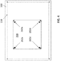
- FIGS. 3 and 4 in accordance with the flowchart of FIG. 6 , a second exemplary process workflow is illustrated conforming to this more foolproof embodiment.
- the cutting system in accordance with step 530, places on the carrier sheet corner indicia 102a-d marking the approximate corners of the expected cut line based upon an expected location for placement of the printing plate.
- the carrier sheet is inspected to determine whether performing step 530 has resulted in one or more of the approximate corner indicia disposed outside of the carrier sheet, and if so, the workflow reverts to step 520, the orientation of the carrier sheet is adjusted, and step 530 is repeated.
- the corner indicia may have any shape or size.
- the carrier sheet is inspected again in step 540, and the workflow is not advanced until performance of steps 520 and 530 results in all of the approximate corner indicia disposed on the carrier sheet.
- the cutting system marks the carrier sheet with plate mounting indicia 104a-d identifying an approximate location and orientation for mounting the printing plate.
- the indicia may take on any shape, size, and number.
- the indicia may comprise a single marking comprising the full outline of the plate to be mounted.
- step 560 the printing plate is mounted in approximate alignment with the plate mounting indicia on the carrier sheet, as shown in FIG. 4 , and in step 570, the camera detects the absolute coordinates of the registration marks 202a-d on the plate.
- step 580 after processing the absolute coordinates of the registration marks as detected to determine the absolute coordinates of the cut line, the cutting system cuts the carrier sheet along the cut line 110.
- a suitable cut file may also contain the instructions for carrying out the steps of this embodiment, including for marking the carrier sheet as described above, and also contains the relative coordinates for the cut line based upon the relative coordinates of the registration marks, as well as absolute coordinates for the four approximate corner marks and for the indicia for approximately aligning the plate on the carrier sheet.
- the carrier sheet is placed on the cutting table, the cut file identifier (read from the printing plate) is entered in the cutting system, the cut file is located and activated, and instructions from the cut file are processed by a processor associated with the cutting system. If the cut file includes instructions for marking the carrier sheet, the four corner indicia are marked, and the system waits for confirmation that the corners are disposed on the plate before advancing to the next set of instructions in the file. If the markings are not all disposed on the carrier sheet, the sheet is repositioned, and the corner marking instructions are re-run. Then the indicia for approximately aligning the plate are printed, and the system waits for confirmation that the plate has been mounted before advancing to the next set of instructions.
- the system Upon receipt of that confirmation, the system then locates the registration marks and cuts the carrier sheet based upon the location and orientation of the registration marks.
- a human operator may perform the steps of placing the carrier sheet on the cutting table, reading and entering the cut file name into the cutting system, checking to ensure the four corner indicia appear on the carrier sheet, and mounting the plate to the carrier sheet, and may provide a signal to the cutting system when each of these steps has been performed, to permit the system workflow to move to the next set of programmed instructions (or to revert back to a prior step, if necessary). It should be understood, however, that each of these steps may be made fully automatic or partially automatic, and that the human operator may rely on various machines and equipment known in the art to provide assistance in performing each step.
- Cutting systems including the computer systems associated therewith, including processors, memory, and various physical and virtual connections between them to permit communication between the various parts of the system, are well known in the art, as are workflow for making printing plates and mounting them on carrier sheets. Accordingly, many of the details that will be well known to those of skill in the art are not repeated here. Exemplary embodiments of such workflows and systems are disclosed in the patents mentioned above. Aspects of the invention include systems comprising processor memories programmed with instructions for performing the processes described herein, as well as computer readable media containing such instructions.
- FIG. 1 depicts an exemplary workflow relevant to the present invention.
- Imager 133 may be configured for direct-to-plate printing on sheets that have an ablatable mask material thereon.
- the imager exposes a mask, e.g., a photographic mask.
- the workflow also includes a UV exposer and washer 135 that is used to cure the sheet with a mask thereon by exposing the front of the plate with the mask thereon to UV radiation.
- the sheet of plate material (after back-radiation) is imaged on the imager.
- the UV exposer and washer 135 includes a mechanism to place a mask on the front of the plate prior to exposure, and it is the mask that comes from the imager and placed with the sheet of plate material after back-exposure.
- An exemplary cutting system includes a cutting table 137, such as but not limited to an Esko Kongsberg-Table (X-Table), which typically includes a tool holder 139 and is operably controlled according to x-y control data.
- the x-y table can operate one of a set of tools in the tool holder 139 under control of the x-y control data, including selecting a tool of the set.
- one tool of the set may be a cutting tool, such as a milling spindle or a knife head, making the x-y table 137 operative to cut segments from a sheet placed on the table according to x-y control data that includes the cutting data 123.
- the x-y table 137 may include a laser positioning tool and in some embodiments, one or more video cameras. The positioning tool and/or the video cameras or both are used to accurately register the position of a sheet of plate material placed on the cutting table.
- the set of tools 139 may include a marking tool, which depending of the embodiment, can be laser tool, a knife tool, a drill tool, or a pen tool, that may be used for placing registration marks on a plate or carrier sheet placed on the table 137.
- the imaging data includes one or more registration marks on the printing plate that are exposed to produce visible registration marks on the plate.
- the imaging data 121 and any x-y control data e.g., mounting data 127 for mounting a printing plate on a carrier sheet, marking data 125 for marking the carrier sheet with a marking tool, and cutting data 123 for cutting the carrier sheet with a cutting tool can all have the same frame of reference on the surface of the sheet when placed on the x-y table 137.
- FIG. 1 shows a controllable x-y table for cutting
- any controllable cutting device can be used for cutting.
- the printing plate After the printing plate has been mounted on the carrier sheet, it may then be used in a printing press 143 to make desired printed matter.
- An exemplary system for mounting a printing plate in accordance with the process disclosed herein comprises at least a cutting system, such as that shown in FIG. 1 , comprising a cutting table 137 for receiving a carrier sheet, a camera (not shown) operable to detect registration marks on a printing plate, a processor for processing coordinates of the detected registration marks and for calculating coordinates for cutting the carrier sheet based upon the detected registration mark coordinates, a cutter (e.g. a cutting tool placed in tool holder 139) for cutting the carrier sheet, and a controller for controlling the cutting system based upon programmed instructions.
- the cutting system also includes a computer memory, readable by a machine, and programmed with instructions for instructing the cutting system controller.
- the processor, controller, and memory are typically part of an integrated processing system that may have a workstation operated by a human user, such as workstation processing system 131 depicted in FIG. 1 .
- the programmed instructions may include at least programming for carrying out the following steps:
- the cutting system is also preferably integrated with a plate maker (e.g. imager 133) programmable to place the one or more registration marks on the printing plate, in which case the programmed instructions further comprise instructions for placing the one or more registration marks on the printing plate and for defining the relative coordinates for location of the cut line based upon relative coordinates of the registration marks.
- a typical cutting system also typically has means for placing indicia on the carrier sheet, such as any of the marking tools in tool set 139, described above.
- the marking means may also be an ink jet printer module operable to dispose ink in accordance with programmed instructions.
- Non-ink indicia may be created using cuts or scores or drill holes made by a cutting or drilling tool or by marks made by a laser, and the marking means may also be a pen (or pencil) tool, comprising a point or stylus that makes physical contact with the carrier sheet, and any and all means for creating marks on a carrier sheet known in the art equivalent to the foregoing.
- the system may also comprise programmed instructions for disposing on the carrier sheet a plurality of corner indicia marking approximate corners of the carrier sheet, and disposing on the carrier sheet plate mounting indicia marking an approximate location and orientation for mounting the printing plate.
- aspects of the invention also include computer readable media containing programmed instructions for controlling a cutting system to facilitate the processes disclosed herein, such as:
- the programmed instructions may also include instructions for disposing on the carrier sheet a plurality of corner indicia marking approximate corners of the carrier sheet, instructions for disposing on the carrier sheet plate mounting indicia marking an approximate location and orientation for mounting the printing plate, and instructions to cause a plate maker to place the registration marks on the printing plate.
- the instructions for causing the plate maker to place the registration marks on the printing plate may comprise a module in the Esko PlatePatcher software that provides instructions for making a single, large plate with such registration marks (rather than multiple small plate pieces, as disclosed in the '291 patent and as heretofore delivered using the PlatePatcher software).
- the invention is not limited to any particular process for providing the registration marks on the printing plate, however.
Claims (15)
- Ein Verfahren zum Montieren einer Druckplatte (200) mit einem ersten Umfang auf einem Trägerbogen (100) mit einem zweiten Umfang, der den ersten Umfang umgibt, wobei das Verfahren die folgenden aufeinanderfolgenden Schritte umfasst:a. Einfügen einer Registermarkierung (registration indicia) (202a, 202d) auf der Druckplatte (200);b. Platzieren des Trägerbogens (100) auf einen Schneidetisch eines Schneidesystems;c. Montieren der Druckplatte (200) auf dem Trägerbogen (100);d. Erfassen, mit dem Schneidesystem, der absoluten Koordinaten der Registermarkierung (202a, 202d) auf der Druckplatte (200); unde. Schneiden des Trägerbogens (100) entlang einer Schnittlinie, die absolute Koordinaten aufweist, die auf der Grundlage der erfassten absoluten Koordinaten der Registermarkierung (202a, 202d) der Druckplatte (200) erzeugt werden.
- Das Verfahren nach Anspruch 1, das ferner Folgendes umfasst:vor Schritt b, Speichern, in einem Systemspeicher, einer der Druckplatte (200) zugeordneten Schneidedatei und Bereitstellen, auf der Druckplatte (200), einer der Schneidedatei entsprechenden Kennung, wobei die Schneidedatei eine Vielzahl von maschinenlesbaren Anweisungen umfasst zum Steuern des Schneidesystems zum Ausführen der Schritte d und e, einschließlich relativer Koordinaten für die Position der Schneidelinie auf der Grundlage der relativen Koordinaten der Registermarkierung der Druckplatte (200); undvor dem Schritt d, Aktivieren der Schneidedatei.
- Das Verfahren nach Anspruch 1, das ferner nach Schritt b und vor Schritt c den folgenden Schritt umfasst:b1. Anordnen, auf dem Trägerbogen (100), einer Vielzahl von Eckzeichen, die die ungefähren Ecken des in Schritt e zu schneidenden Trägerbogens markieren, undb2. Anordnen, auf dem Trägerbogen (100), von Plattenbefestigungs-Zeichen, die eine ungefähre Position und Ausrichtung zur Montage der Druckplatte (200) in Schritt c markieren.
- Das Verfahren nach Anspruch 3, das ferner Folgendes umfasst:
Überprüfen, ob einer oder mehrere von der Vielzahl von in Schritt b1 platzierten Eckzeichen außerhalb des Trägerbogens (100) angeordnet sind, und wenn dies der Fall ist: Wiederholen von Schritt b, um die Platzierung des Trägerbogens (100) anzupassen, und dann: Wiederholen von Schritt b1. - Das Verfahren nach Anspruch 3, das ferner Folgendes umfasst:vor Schritt b, Speichern, in einem Systemspeicher, einer der Druckplatte (200) zugeordneten Schneidedatei, wobei die Schneidedatei eine Vielzahl von maschinenlesbaren Anweisungen umfasst zum Steuern des Schneidesystems zum Ausführen der Schritte b1, b2, d und e, zum Bereitstellen einer der Schneidedatei entsprechenden Kennung auf der Druckplatte (200), und die Folgendes enthalten: relative Koordinaten für die Position der Schneidelinie auf der Grundlage von relativen Koordinaten der Registermarkierung der Druckplatte (200) und absolute Koordinaten für die Position der Eck- und Plattenbefestigungs-Zeichen, die auf dem Trägerbogen (100) zu markieren sind; undvor dem Schritt b1, Aktivieren der Schneidedatei.
- Ein System zum Schneiden eines Trägerbogens (100), wobei der Trägerbogen (100) einen zweiten Umfang aufweist, der einen Umfang einer Druckplatte (200) umgibt, die einen ersten Umfang aufweist und auf dem Trägerbogen (100) montiert ist, wobei das System Folgendes umfasst:ein Schneidesystem, das Folgendes umfasst: einen Schneidetisch zum Aufnehmen des Trägerbogens (100), eine Kamera, die betreibbar ist, um eine Registermarkierung auf der Druckplatte (200) zu erfassen, einen Prozessor zum Verarbeiten von Koordinaten der erfassten Registermarkierung und zum Berechnen von Koordinaten zum Schneiden des Trägerbogens (100) auf der Grundlage der Koordinaten der erfassten Registermarkierung, eine Schneidevorrichtung zum Schneiden des Trägerbogens (100), und eine Steuerung zum Steuern des Schneidesystems auf der Grundlage von programmierten Anweisungen;einen Computerspeicher, der von einer Maschine lesbar ist und mit Anweisungen programmiert ist, um die Steuerung des Schneidesystems anzuweisen, Schritte durchzuführen, die Folgendes umfassen:a. Erfassen, mit der Schneidesystem-Kamera, absoluter Koordinaten einer Registermarkierung auf der Druckplatte (200), die auf dem Trägerbogen (100) angebracht ist;b. Berechnen absoluter Koordinaten für die Schnittlinie auf der Grundlage der erfassten absoluten Koordinaten der Registermarkierung der Druckplatte (200) in Übereinstimmung mit gespeicherten relativen Koordinaten für die Position der Schnittlinie auf der Grundlage der relativen Koordinaten der Registermarkierung; undc. Schneiden des Trägerbogens (100) entlang der Schnittlinie.
- Das System nach Anspruch 6, das ferner einen Plattenformer (plate maker) umfasst, der so programmiert werden kann, dass er die Registermarkierung auf der Druckplatte (200) platziert, wobei die programmierten Anweisungen ferner Anweisungen umfassen zum Platzieren der Registermarkierung auf der Druckplatte (200) und zum Definieren der relativen Koordinaten für die Position der Schnittlinie auf der Grundlage der relativen Koordinaten der Registermarkierung.
- Das System nach Anspruch 6, wobei das Schneidesystem ferner Mittel zum Platzieren von Zeichen auf dem Trägerbogen (100) umfasst, und wobei die programmierten Anweisungen ferner Anweisungen umfassen zum Anordnen einer Vielzahl von Eckzeichen auf dem Trägerbogen (100), die ungefähre Ecken des Trägerbogens (100) markieren, und zum Anordnen von Plattenbefestigungs-Zeichen auf dem Trägerbogen (100), die eine ungefähre Position und Ausrichtung für die Montage der Druckplatte (200) markieren.
- Computerlesbare Medien, die programmierte Anweisungen zur Steuerung eines Schneidsystems enthalten, um die Montage einer Druckplatte (200) mit einem ersten Umfang auf einem Trägerbogen (100) mit einem zweiten Umfang, der den ersten Umfang umgibt, zu erleichtern, wobei die Anweisungen Folgendes umfassen:a. Anweisungen zum Definieren von relativen Koordinaten für die Position einer Schnittlinie auf dem Trägerbogen (100) auf der Grundlage von relativen Koordinaten der Registermarkierung auf der Druckplatte (200);b. Anweisungen zum Erfassen, mit dem Schneidesystem, absoluter Koordinaten der Registermarkierung auf der Druckplatte (200), die auf dem Trägerbogen (100) montiert ist;c. Anweisungen zum Berechnen absoluter Koordinaten für die Schnittlinie auf der Grundlage der erfassten absoluten Koordinaten der Registermarkierung der Druckplatte (200), und der relativen Koordinaten für die Position der Schnittlinie auf der Grundlage der relativen Koordinaten der Registermarkierung der Druckplatte (200); undd. Anweisungen, um das Schneidesystem zu veranlassen, den Trägerbogen (100) entlang der Schnittlinie zu schneiden.
- Das computerlesbare Medium nach Anspruch 9, das ferner programmierte Anweisungen umfasst, um auf dem Trägerbogen (100) eine Vielzahl von Eckzeichen anzuordnen, die ungefähre Ecken des Trägerbogens (100) markieren, und um auf dem Trägerbogen (100) Plattenbefestigungs-Zeichen anzuordnen, die eine ungefähre Position und Ausrichtung zur Montage der Druckplatte (200) markieren.
- Das computerlesbare Medium nach Anspruch 9, das ferner programmierte Anweisungen umfasst, um einen Plattenformer anzuweisen, die Registermarkierung auf der Druckplatte (200) zu platzieren.
- Das Verfahren nach irgendeinem der Ansprüche von 1 bis 5, wobei die Registermarkierung eine Vielzahl von Passermarken umfasst.
- Das Verfahren nach Anspruch 12, wobei die Vielzahl der Passermarken zwei, drei oder vier Passermarken umfasst.
- Das System nach irgendeinem der Ansprüche von 6 bis 8, wobei die Registermarkierung eine Vielzahl von Passermarken umfasst, insbesondere wobei die Vielzahl von Passermarken zwei, drei oder vier Passermarken umfasst.
- Das computerlesbare Medium nach irgendeinem der Ansprüche von 9 bis 11, wobei die Registermarkierung eine Vielzahl von Passermarken umfasst, insbesondere wobei die Vielzahl von Passermarken zwei, drei oder vier Passermarken umfasst.
Priority Applications (1)
| Application Number | Priority Date | Filing Date | Title |
|---|---|---|---|
| EP21194999.5A EP3971649B1 (de) | 2016-07-21 | 2017-07-20 | System und verfahren zur montage einer druckplatte auf einem träger |
Applications Claiming Priority (2)
| Application Number | Priority Date | Filing Date | Title |
|---|---|---|---|
| US201662365041P | 2016-07-21 | 2016-07-21 | |
| PCT/EP2017/068385 WO2018015500A1 (en) | 2016-07-21 | 2017-07-20 | System and process for mounting a printing plate on a carrier |
Related Child Applications (1)
| Application Number | Title | Priority Date | Filing Date |
|---|---|---|---|
| EP21194999.5A Division EP3971649B1 (de) | 2016-07-21 | 2017-07-20 | System und verfahren zur montage einer druckplatte auf einem träger |
Publications (2)
| Publication Number | Publication Date |
|---|---|
| EP3488295A1 EP3488295A1 (de) | 2019-05-29 |
| EP3488295B1 true EP3488295B1 (de) | 2021-09-22 |
Family
ID=59558383
Family Applications (2)
| Application Number | Title | Priority Date | Filing Date |
|---|---|---|---|
| EP17749141.2A Active EP3488295B1 (de) | 2016-07-21 | 2017-07-20 | System und verfahren zur montage einer druckplatte auf einem träger |
| EP21194999.5A Active EP3971649B1 (de) | 2016-07-21 | 2017-07-20 | System und verfahren zur montage einer druckplatte auf einem träger |
Family Applications After (1)
| Application Number | Title | Priority Date | Filing Date |
|---|---|---|---|
| EP21194999.5A Active EP3971649B1 (de) | 2016-07-21 | 2017-07-20 | System und verfahren zur montage einer druckplatte auf einem träger |
Country Status (4)
| Country | Link |
|---|---|
| US (2) | US10828917B2 (de) |
| EP (2) | EP3488295B1 (de) |
| CN (1) | CN109690417B (de) |
| WO (1) | WO2018015500A1 (de) |
Families Citing this family (6)
| Publication number | Priority date | Publication date | Assignee | Title |
|---|---|---|---|---|
| ES2903231T3 (es) | 2008-02-26 | 2022-03-31 | Jenavalve Tech Inc | Stent para el posicionamiento y anclaje de una prótesis valvular en un sitio de implantación en el corazón de un paciente |
| EP3488295B1 (de) * | 2016-07-21 | 2021-09-22 | Esko-Graphics Imaging GmbH | System und verfahren zur montage einer druckplatte auf einem träger |
| EP3672809B1 (de) | 2017-08-24 | 2022-01-19 | Esko-Graphics Imaging GmbH | System und verfahren zur montage eines druckplattensegments |
| CN109471335B (zh) * | 2018-12-31 | 2023-10-31 | 深圳市路维光电股份有限公司 | 铬版贴片治具及方法 |
| US11340843B2 (en) | 2019-05-17 | 2022-05-24 | Esko-Graphics Imaging Gmbh | System and method for storing interrelated image information in a print job file |
| JP2022159645A (ja) * | 2021-04-05 | 2022-10-18 | セイコーエプソン株式会社 | 情報処理方法、情報処理装置、及び情報処理用プログラム |
Family Cites Families (33)
| Publication number | Priority date | Publication date | Assignee | Title |
|---|---|---|---|---|
| JPH06105348B2 (ja) * | 1988-06-28 | 1994-12-21 | 大日本スクリーン製造株式会社 | 原板フィルム貼り込みシステムおよびそのシステムに用いるフィルムパンチ・カット装置 |
| US5333111A (en) | 1991-05-02 | 1994-07-26 | Gerber Garment Technology, Inc. | Garment cutting system having computer assisted pattern alignment |
| DE4130359C2 (de) | 1991-09-12 | 1997-04-17 | Heidelberger Druckmasch Ag | Vorrichtung zum Ab- und/oder Zuführen von Druckplatten einer Druckmaschine |
| EP0769761A1 (de) | 1995-10-12 | 1997-04-23 | Schablonentechnik Kufstein Aktiengesellschaft | Musterbildungsverfahren |
| US5846691A (en) * | 1996-07-08 | 1998-12-08 | Polyfibron Technologies, Inc. | Composite relief image printing plates and methods for preparing same |
| US6434444B2 (en) * | 1997-03-12 | 2002-08-13 | Gerber Technology, Inc. | Method and apparatus for transforming a part periphery to be cut from a patterned sheet material |
| US5850789A (en) | 1997-07-22 | 1998-12-22 | E. I. Du Pont De Nemours And Company | Method and apparatus for mounting printing plates |
| US6173211B1 (en) | 1998-04-15 | 2001-01-09 | Gerber Technology, Inc. | Apparatus and method for fabric printing of nested |
| US6258495B1 (en) | 1998-09-14 | 2001-07-10 | Orc Manufacturing Co., Ltd. | Process for aligning work and mask |
| KR100421551B1 (ko) | 2000-12-16 | 2004-03-09 | 삼성아토피나주식회사 | 올레핀 전중합 촉매 및 이를 이용한 올레핀 중합방법 |
| US6954291B2 (en) | 2001-09-04 | 2005-10-11 | Esko-Graphics A/S | Method, apparatus, and computer program for reducing plate material waste in flexography plate making |
| ATE348686T1 (de) | 2002-04-26 | 2007-01-15 | Strobbe Graphics N V | Positioniervorrichtung, insbesondere für offsetdruckplatten |
| US7040204B2 (en) | 2002-10-30 | 2006-05-09 | Mikkelsen Graphic Engineering | Method for preparing graphics on sheets |
| US6823793B2 (en) | 2003-01-06 | 2004-11-30 | Esko Graphics, Nv | Method and apparatus for mounting flexographic plate segments |
| US7182007B2 (en) | 2004-01-29 | 2007-02-27 | Esko-Graphics A/S | Method for dynamically aligning substrates bearing printed reference marks and codes for automated cutting or scoring, and substrates so cut or scored |
| CN1872505A (zh) * | 2004-06-03 | 2006-12-06 | 富士胶片株式会社 | 喷墨用记录纸的制作方法 |
| JP4586631B2 (ja) * | 2005-05-25 | 2010-11-24 | コニカミノルタビジネステクノロジーズ株式会社 | 画像形成装置 |
| US7854199B2 (en) | 2007-03-29 | 2010-12-21 | Eastman Kodak Company | Printing plate registration using a camera |
| US7819060B2 (en) | 2007-04-13 | 2010-10-26 | E.I. Du Pont De Nemours And Company | Method for mounting cylindrically-shaped printing forms |
| CA2637371C (en) | 2007-07-14 | 2012-07-03 | Manroland Ag | Handling device of a printing press |
| US8009330B2 (en) | 2008-02-05 | 2011-08-30 | Eastman Kodak Company | Method for imaging flexographic plates |
| JP5060404B2 (ja) * | 2008-06-20 | 2012-10-31 | キヤノン株式会社 | 画像処理装置、画像処理方法、およびプログラム |
| EP2386413B1 (de) | 2010-05-04 | 2013-08-21 | Goss International Montataire SA | Vorrichtung zur Identifizierung von Druckplatten, zugehörige Druckpresse und Verfahren |
| US9375916B2 (en) | 2010-06-18 | 2016-06-28 | Esko-Graphics Imaging Gmbh | Non-printing registration marks on a printing plate |
| FR2962828B1 (fr) | 2010-07-19 | 2012-08-17 | Advanced Track & Trace | Procedes et dispositifs de marquage et d'authentification d'un produit par un consommateur. |
| EP2428360B1 (de) | 2010-09-10 | 2017-03-15 | Bobst Bielefeld GmbH | Verfahren und vorrichtung zur montage von druckplatten |
| CN102001218A (zh) | 2010-09-25 | 2011-04-06 | 黄景温 | 移印机自动调校装置 |
| US20140115886A1 (en) * | 2012-10-26 | 2014-05-01 | Volex Plc | Method and system for marking substrate and placing components for high accuracy |
| US9902146B2 (en) | 2013-01-29 | 2018-02-27 | Gerald J. Gartner and Teresa Ann Gartner, or their successors | System and method for aligning, mounting and recording alignment of a mounted printing plate |
| US9747681B2 (en) | 2013-03-27 | 2017-08-29 | Prosper Creative Co., Ltd. | Measuring apparatus, measurement method, information processing apparatus, and measurement program |
| CN103955112B (zh) | 2014-05-12 | 2015-11-18 | 青岛斯博锐意电子技术有限公司 | 一种计算机成像直接制版设备及制版方法 |
| EP3488295B1 (de) * | 2016-07-21 | 2021-09-22 | Esko-Graphics Imaging GmbH | System und verfahren zur montage einer druckplatte auf einem träger |
| EP3672809B1 (de) | 2017-08-24 | 2022-01-19 | Esko-Graphics Imaging GmbH | System und verfahren zur montage eines druckplattensegments |
-
2017
- 2017-07-20 EP EP17749141.2A patent/EP3488295B1/de active Active
- 2017-07-20 EP EP21194999.5A patent/EP3971649B1/de active Active
- 2017-07-20 CN CN201780045083.8A patent/CN109690417B/zh active Active
- 2017-07-20 US US16/319,108 patent/US10828917B2/en active Active
- 2017-07-20 WO PCT/EP2017/068385 patent/WO2018015500A1/en unknown
-
2020
- 2020-11-09 US US17/092,880 patent/US11639069B2/en active Active
Also Published As
| Publication number | Publication date |
|---|---|
| WO2018015500A1 (en) | 2018-01-25 |
| US10828917B2 (en) | 2020-11-10 |
| EP3971649B1 (de) | 2023-12-27 |
| EP3971649A1 (de) | 2022-03-23 |
| EP3488295A1 (de) | 2019-05-29 |
| US20200164666A1 (en) | 2020-05-28 |
| CN109690417B (zh) | 2021-08-06 |
| US11639069B2 (en) | 2023-05-02 |
| US20210053374A1 (en) | 2021-02-25 |
| CN109690417A (zh) | 2019-04-26 |
Similar Documents
| Publication | Publication Date | Title |
|---|---|---|
| US11639069B2 (en) | System and process for mounting a printing plate on a carrier | |
| EP2397327A2 (de) | Nichtdruckende Registrierungsmarkierungen auf einer Druckplatte | |
| EP3672809B1 (de) | System und verfahren zur montage eines druckplattensegments | |
| US8009330B2 (en) | Method for imaging flexographic plates | |
| US20030075257A1 (en) | Flexographic printing method | |
| EP1543966B1 (de) | Verfahren und Vorrichtung zur Erfassung der Fuge eines Flexodruckplattenvorläufers | |
| US5661566A (en) | Method for making a plurality of printing plates | |
| US11201973B2 (en) | Printing system for printing alignment mark and method of controlling printing system for printing alignment mark | |
| JP2001187481A (ja) | ドキュメント仕上方法及び装置 | |
| KR102554316B1 (ko) | 판처리장치 및 판처리방법 | |
| FI81917C (fi) | Metod och apparat foer automatisering av utskjutningsarbetsfasen i en reproduktionsanlaeggning. | |
| JP2001191482A (ja) | プリント配線板の印刷装置及び印刷方法 | |
| EP0810914A1 (de) | Verfahren sowie vorrichtung zum perforieren | |
| JP2002351649A (ja) | 面付けシステム、面付け方法、面付けプログラム、及び面付けプログラムを記録した記録媒体 | |
| JP2003246038A (ja) | 印刷版の面付け方法および印刷物の印刷ズレ判別方法 | |
| KR20000020284A (ko) | 인쇄기기의 비규격 용지 인쇄방법 |
Legal Events
| Date | Code | Title | Description |
|---|---|---|---|
| STAA | Information on the status of an ep patent application or granted ep patent |
Free format text: STATUS: UNKNOWN |
|
| STAA | Information on the status of an ep patent application or granted ep patent |
Free format text: STATUS: THE INTERNATIONAL PUBLICATION HAS BEEN MADE |
|
| PUAI | Public reference made under article 153(3) epc to a published international application that has entered the european phase |
Free format text: ORIGINAL CODE: 0009012 |
|
| STAA | Information on the status of an ep patent application or granted ep patent |
Free format text: STATUS: REQUEST FOR EXAMINATION WAS MADE |
|
| 17P | Request for examination filed |
Effective date: 20190220 |
|
| AK | Designated contracting states |
Kind code of ref document: A1 Designated state(s): AL AT BE BG CH CY CZ DE DK EE ES FI FR GB GR HR HU IE IS IT LI LT LU LV MC MK MT NL NO PL PT RO RS SE SI SK SM TR |
|
| AX | Request for extension of the european patent |
Extension state: BA ME |
|
| DAV | Request for validation of the european patent (deleted) | ||
| DAX | Request for extension of the european patent (deleted) | ||
| GRAP | Despatch of communication of intention to grant a patent |
Free format text: ORIGINAL CODE: EPIDOSNIGR1 |
|
| STAA | Information on the status of an ep patent application or granted ep patent |
Free format text: STATUS: GRANT OF PATENT IS INTENDED |
|
| INTG | Intention to grant announced |
Effective date: 20210430 |
|
| GRAS | Grant fee paid |
Free format text: ORIGINAL CODE: EPIDOSNIGR3 |
|
| GRAA | (expected) grant |
Free format text: ORIGINAL CODE: 0009210 |
|
| STAA | Information on the status of an ep patent application or granted ep patent |
Free format text: STATUS: THE PATENT HAS BEEN GRANTED |
|
| AK | Designated contracting states |
Kind code of ref document: B1 Designated state(s): AL AT BE BG CH CY CZ DE DK EE ES FI FR GB GR HR HU IE IS IT LI LT LU LV MC MK MT NL NO PL PT RO RS SE SI SK SM TR |
|
| REG | Reference to a national code |
Ref country code: GB Ref legal event code: FG4D |
|
| REG | Reference to a national code |
Ref country code: IE Ref legal event code: FG4D |
|
| REG | Reference to a national code |
Ref country code: DE Ref legal event code: R096 Ref document number: 602017046398 Country of ref document: DE |
|
| REG | Reference to a national code |
Ref country code: CH Ref legal event code: EP Ref country code: AT Ref legal event code: REF Ref document number: 1432790 Country of ref document: AT Kind code of ref document: T Effective date: 20211015 |
|
| REG | Reference to a national code |
Ref country code: NL Ref legal event code: FP |
|
| REG | Reference to a national code |
Ref country code: LT Ref legal event code: MG9D |
|
| REG | Reference to a national code |
Ref country code: NO Ref legal event code: T2 Effective date: 20210922 |
|
| PG25 | Lapsed in a contracting state [announced via postgrant information from national office to epo] |
Ref country code: HR Free format text: LAPSE BECAUSE OF FAILURE TO SUBMIT A TRANSLATION OF THE DESCRIPTION OR TO PAY THE FEE WITHIN THE PRESCRIBED TIME-LIMIT Effective date: 20210922 Ref country code: SE Free format text: LAPSE BECAUSE OF FAILURE TO SUBMIT A TRANSLATION OF THE DESCRIPTION OR TO PAY THE FEE WITHIN THE PRESCRIBED TIME-LIMIT Effective date: 20210922 Ref country code: RS Free format text: LAPSE BECAUSE OF FAILURE TO SUBMIT A TRANSLATION OF THE DESCRIPTION OR TO PAY THE FEE WITHIN THE PRESCRIBED TIME-LIMIT Effective date: 20210922 Ref country code: LT Free format text: LAPSE BECAUSE OF FAILURE TO SUBMIT A TRANSLATION OF THE DESCRIPTION OR TO PAY THE FEE WITHIN THE PRESCRIBED TIME-LIMIT Effective date: 20210922 Ref country code: BG Free format text: LAPSE BECAUSE OF FAILURE TO SUBMIT A TRANSLATION OF THE DESCRIPTION OR TO PAY THE FEE WITHIN THE PRESCRIBED TIME-LIMIT Effective date: 20211222 Ref country code: FI Free format text: LAPSE BECAUSE OF FAILURE TO SUBMIT A TRANSLATION OF THE DESCRIPTION OR TO PAY THE FEE WITHIN THE PRESCRIBED TIME-LIMIT Effective date: 20210922 |
|
| REG | Reference to a national code |
Ref country code: AT Ref legal event code: MK05 Ref document number: 1432790 Country of ref document: AT Kind code of ref document: T Effective date: 20210922 |
|
| PG25 | Lapsed in a contracting state [announced via postgrant information from national office to epo] |
Ref country code: LV Free format text: LAPSE BECAUSE OF FAILURE TO SUBMIT A TRANSLATION OF THE DESCRIPTION OR TO PAY THE FEE WITHIN THE PRESCRIBED TIME-LIMIT Effective date: 20210922 Ref country code: GR Free format text: LAPSE BECAUSE OF FAILURE TO SUBMIT A TRANSLATION OF THE DESCRIPTION OR TO PAY THE FEE WITHIN THE PRESCRIBED TIME-LIMIT Effective date: 20211223 |
|
| PG25 | Lapsed in a contracting state [announced via postgrant information from national office to epo] |
Ref country code: AT Free format text: LAPSE BECAUSE OF FAILURE TO SUBMIT A TRANSLATION OF THE DESCRIPTION OR TO PAY THE FEE WITHIN THE PRESCRIBED TIME-LIMIT Effective date: 20210922 |
|
| PG25 | Lapsed in a contracting state [announced via postgrant information from national office to epo] |
Ref country code: IS Free format text: LAPSE BECAUSE OF FAILURE TO SUBMIT A TRANSLATION OF THE DESCRIPTION OR TO PAY THE FEE WITHIN THE PRESCRIBED TIME-LIMIT Effective date: 20220122 Ref country code: SK Free format text: LAPSE BECAUSE OF FAILURE TO SUBMIT A TRANSLATION OF THE DESCRIPTION OR TO PAY THE FEE WITHIN THE PRESCRIBED TIME-LIMIT Effective date: 20210922 Ref country code: RO Free format text: LAPSE BECAUSE OF FAILURE TO SUBMIT A TRANSLATION OF THE DESCRIPTION OR TO PAY THE FEE WITHIN THE PRESCRIBED TIME-LIMIT Effective date: 20210922 Ref country code: PT Free format text: LAPSE BECAUSE OF FAILURE TO SUBMIT A TRANSLATION OF THE DESCRIPTION OR TO PAY THE FEE WITHIN THE PRESCRIBED TIME-LIMIT Effective date: 20220124 Ref country code: PL Free format text: LAPSE BECAUSE OF FAILURE TO SUBMIT A TRANSLATION OF THE DESCRIPTION OR TO PAY THE FEE WITHIN THE PRESCRIBED TIME-LIMIT Effective date: 20210922 Ref country code: ES Free format text: LAPSE BECAUSE OF FAILURE TO SUBMIT A TRANSLATION OF THE DESCRIPTION OR TO PAY THE FEE WITHIN THE PRESCRIBED TIME-LIMIT Effective date: 20210922 Ref country code: EE Free format text: LAPSE BECAUSE OF FAILURE TO SUBMIT A TRANSLATION OF THE DESCRIPTION OR TO PAY THE FEE WITHIN THE PRESCRIBED TIME-LIMIT Effective date: 20210922 Ref country code: CZ Free format text: LAPSE BECAUSE OF FAILURE TO SUBMIT A TRANSLATION OF THE DESCRIPTION OR TO PAY THE FEE WITHIN THE PRESCRIBED TIME-LIMIT Effective date: 20210922 Ref country code: AL Free format text: LAPSE BECAUSE OF FAILURE TO SUBMIT A TRANSLATION OF THE DESCRIPTION OR TO PAY THE FEE WITHIN THE PRESCRIBED TIME-LIMIT Effective date: 20210922 |
|
| REG | Reference to a national code |
Ref country code: DE Ref legal event code: R097 Ref document number: 602017046398 Country of ref document: DE |
|
| PG25 | Lapsed in a contracting state [announced via postgrant information from national office to epo] |
Ref country code: DK Free format text: LAPSE BECAUSE OF FAILURE TO SUBMIT A TRANSLATION OF THE DESCRIPTION OR TO PAY THE FEE WITHIN THE PRESCRIBED TIME-LIMIT Effective date: 20210922 |
|
| PLBE | No opposition filed within time limit |
Free format text: ORIGINAL CODE: 0009261 |
|
| STAA | Information on the status of an ep patent application or granted ep patent |
Free format text: STATUS: NO OPPOSITION FILED WITHIN TIME LIMIT |
|
| 26N | No opposition filed |
Effective date: 20220623 |
|
| PG25 | Lapsed in a contracting state [announced via postgrant information from national office to epo] |
Ref country code: SI Free format text: LAPSE BECAUSE OF FAILURE TO SUBMIT A TRANSLATION OF THE DESCRIPTION OR TO PAY THE FEE WITHIN THE PRESCRIBED TIME-LIMIT Effective date: 20210922 |
|
| PG25 | Lapsed in a contracting state [announced via postgrant information from national office to epo] |
Ref country code: IT Free format text: LAPSE BECAUSE OF FAILURE TO SUBMIT A TRANSLATION OF THE DESCRIPTION OR TO PAY THE FEE WITHIN THE PRESCRIBED TIME-LIMIT Effective date: 20210922 |
|
| PG25 | Lapsed in a contracting state [announced via postgrant information from national office to epo] |
Ref country code: MC Free format text: LAPSE BECAUSE OF FAILURE TO SUBMIT A TRANSLATION OF THE DESCRIPTION OR TO PAY THE FEE WITHIN THE PRESCRIBED TIME-LIMIT Effective date: 20210922 |
|
| GBPC | Gb: european patent ceased through non-payment of renewal fee |
Effective date: 20220720 |
|
| PG25 | Lapsed in a contracting state [announced via postgrant information from national office to epo] |
Ref country code: LU Free format text: LAPSE BECAUSE OF NON-PAYMENT OF DUE FEES Effective date: 20220720 Ref country code: FR Free format text: LAPSE BECAUSE OF NON-PAYMENT OF DUE FEES Effective date: 20220731 |
|
| PG25 | Lapsed in a contracting state [announced via postgrant information from national office to epo] |
Ref country code: GB Free format text: LAPSE BECAUSE OF NON-PAYMENT OF DUE FEES Effective date: 20220720 |
|
| PG25 | Lapsed in a contracting state [announced via postgrant information from national office to epo] |
Ref country code: IE Free format text: LAPSE BECAUSE OF NON-PAYMENT OF DUE FEES Effective date: 20220720 |
|
| PGFP | Annual fee paid to national office [announced via postgrant information from national office to epo] |
Ref country code: NL Payment date: 20230614 Year of fee payment: 7 |
|
| PGFP | Annual fee paid to national office [announced via postgrant information from national office to epo] |
Ref country code: BE Payment date: 20230616 Year of fee payment: 7 |
|
| PGFP | Annual fee paid to national office [announced via postgrant information from national office to epo] |
Ref country code: NO Payment date: 20230712 Year of fee payment: 7 Ref country code: CH Payment date: 20230801 Year of fee payment: 7 |
|
| PGFP | Annual fee paid to national office [announced via postgrant information from national office to epo] |
Ref country code: DE Payment date: 20230524 Year of fee payment: 7 |
|
| PG25 | Lapsed in a contracting state [announced via postgrant information from national office to epo] |
Ref country code: HU Free format text: LAPSE BECAUSE OF FAILURE TO SUBMIT A TRANSLATION OF THE DESCRIPTION OR TO PAY THE FEE WITHIN THE PRESCRIBED TIME-LIMIT; INVALID AB INITIO Effective date: 20170720 |