EP3487329B1 - Vorrichtung zur neuausrichtung simulierter zigarettenteile - Google Patents
Vorrichtung zur neuausrichtung simulierter zigarettenteile Download PDFInfo
- Publication number
- EP3487329B1 EP3487329B1 EP17754813.8A EP17754813A EP3487329B1 EP 3487329 B1 EP3487329 B1 EP 3487329B1 EP 17754813 A EP17754813 A EP 17754813A EP 3487329 B1 EP3487329 B1 EP 3487329B1
- Authority
- EP
- European Patent Office
- Prior art keywords
- reorienting
- simulated cigarette
- section
- unit
- cam
- Prior art date
- Legal status (The legal status is an assumption and is not a legal conclusion. Google has not performed a legal analysis and makes no representation as to the accuracy of the status listed.)
- Active
Links
- 235000019504 cigarettes Nutrition 0.000 title claims description 95
- 230000005540 biological transmission Effects 0.000 claims description 34
- 230000013011 mating Effects 0.000 claims description 34
- 239000000969 carrier Substances 0.000 claims description 27
- 230000007246 mechanism Effects 0.000 claims description 22
- 238000000034 method Methods 0.000 claims description 13
- 238000011144 upstream manufacturing Methods 0.000 claims description 7
- 238000003825 pressing Methods 0.000 description 5
- 238000006073 displacement reaction Methods 0.000 description 4
- 238000004519 manufacturing process Methods 0.000 description 2
- 230000001419 dependent effect Effects 0.000 description 1
- 239000003571 electronic cigarette Substances 0.000 description 1
Images


Classifications
-
- A—HUMAN NECESSITIES
- A24—TOBACCO; CIGARS; CIGARETTES; SIMULATED SMOKING DEVICES; SMOKERS' REQUISITES
- A24F—SMOKERS' REQUISITES; MATCH BOXES; SIMULATED SMOKING DEVICES
- A24F40/00—Electrically operated smoking devices; Component parts thereof; Manufacture thereof; Maintenance or testing thereof; Charging means specially adapted therefor
- A24F40/70—Manufacture
-
- B—PERFORMING OPERATIONS; TRANSPORTING
- B65—CONVEYING; PACKING; STORING; HANDLING THIN OR FILAMENTARY MATERIAL
- B65G—TRANSPORT OR STORAGE DEVICES, e.g. CONVEYORS FOR LOADING OR TIPPING, SHOP CONVEYOR SYSTEMS OR PNEUMATIC TUBE CONVEYORS
- B65G47/00—Article or material-handling devices associated with conveyors; Methods employing such devices
- B65G47/22—Devices influencing the relative position or the attitude of articles during transit by conveyors
- B65G47/24—Devices influencing the relative position or the attitude of articles during transit by conveyors orientating the articles
-
- B—PERFORMING OPERATIONS; TRANSPORTING
- B65—CONVEYING; PACKING; STORING; HANDLING THIN OR FILAMENTARY MATERIAL
- B65G—TRANSPORT OR STORAGE DEVICES, e.g. CONVEYORS FOR LOADING OR TIPPING, SHOP CONVEYOR SYSTEMS OR PNEUMATIC TUBE CONVEYORS
- B65G2201/00—Indexing codes relating to handling devices, e.g. conveyors, characterised by the type of product or load being conveyed or handled
- B65G2201/02—Articles
- B65G2201/0226—Cigarettes
-
- B—PERFORMING OPERATIONS; TRANSPORTING
- B65—CONVEYING; PACKING; STORING; HANDLING THIN OR FILAMENTARY MATERIAL
- B65G—TRANSPORT OR STORAGE DEVICES, e.g. CONVEYORS FOR LOADING OR TIPPING, SHOP CONVEYOR SYSTEMS OR PNEUMATIC TUBE CONVEYORS
- B65G29/00—Rotary conveyors, e.g. rotating discs, arms, star-wheels or cones
-
- B—PERFORMING OPERATIONS; TRANSPORTING
- B65—CONVEYING; PACKING; STORING; HANDLING THIN OR FILAMENTARY MATERIAL
- B65G—TRANSPORT OR STORAGE DEVICES, e.g. CONVEYORS FOR LOADING OR TIPPING, SHOP CONVEYOR SYSTEMS OR PNEUMATIC TUBE CONVEYORS
- B65G47/00—Article or material-handling devices associated with conveyors; Methods employing such devices
- B65G47/34—Devices for discharging articles or materials from conveyor
- B65G47/46—Devices for discharging articles or materials from conveyor and distributing, e.g. automatically, to desired points
- B65G47/51—Devices for discharging articles or materials from conveyor and distributing, e.g. automatically, to desired points according to unprogrammed signals, e.g. influenced by supply situation at destination
- B65G47/5104—Devices for discharging articles or materials from conveyor and distributing, e.g. automatically, to desired points according to unprogrammed signals, e.g. influenced by supply situation at destination for articles
- B65G47/5109—Devices for discharging articles or materials from conveyor and distributing, e.g. automatically, to desired points according to unprogrammed signals, e.g. influenced by supply situation at destination for articles first In - First Out systems: FIFO
- B65G47/5136—Devices for discharging articles or materials from conveyor and distributing, e.g. automatically, to desired points according to unprogrammed signals, e.g. influenced by supply situation at destination for articles first In - First Out systems: FIFO using rotary conveyors
Definitions
- the present invention relates to a reorienting device for reorienting simulated cigarette parts (also: parts) relative to a product carrier in which they are supported to a predetermined orientation.
- the parts are received from a first track, reoriented and delivered to a second track in the predetermined orientation relative to the product carrier.
- the present invention also relates to a method of reorienting simulated cigarette parts.
- a manufacturing process of parts of a simulated cigarette various processing operations generally need to be carried out on the parts.
- the parts are generally carried by a product carrier.
- the parts may be relatively small and may be quite fragile.
- the processing operations may need to be carried out in a specific way.
- the possibilities of controlling the position and orientation of these parts relative to the product carrier during the various processing steps in an assembly line are limited.
- the orientation of the parts may be random during the conveying of the parts through an assembly line, and this may seriously hinder a processing operation.
- the parts may simply have a wrong orientation so that it becomes impossible to carry out the processing operation.
- WO 2012/077147 A1 discloses a series of article-handling machines comprising a common first rotating element rotatable about an axis, wherein each article-handling machine comprises a carousel for conveying a plurality of articles along a path and a first connecting element which is angularly integral with carousel and is releasably connected to first rotating element.
- DE 37 28 291 A1 discloses a process and apparatus for arranging and holding a plurality of pack units in a common receiving container. Individual bottles are to be placed and held in the compartments of the bottle case in such a rotary position that the label remains visible on the outside.
- the first orientation may be a random orientation.
- the invention relates to a reorienting device for reorienting simulated cigarette parts which are carried by a product carrier about a vertical product axis from a first angular orientation to a second, predetermined orientation relative to said product carrier, the reorienting device comprising:
- the present invention was found to provide a reliable and effective way of reorienting the products in their product carriers.
- the first section of the reorienting unit is movable between an upper position and a lower position and the second section is fixed in a direction of the unit axis.
- the resilient member of the reorienting unit vertically displaces the first section and biases the first section in a downward direction.
- the first cam track has a varying radius R relative to the main axis of rotation causing a radial movement of the cam when the cam travels along the first cam track during the rotary movement of the rotary carrousel.
- each transmission mechanism comprises a transmission gear which is attached to the cam.
- Each reorienting unit comprises an actuating gear.
- the actuating gear extends around the unit axis and engages the transmission gear of the transmission mechanism.
- a radial movement of the cam results in a movement of the transmission gear.
- the movement of the transmission gear results in turn in a movement of the actuating gear.
- the second cam track comprises:
- the second cam track further comprises a substantially horizontal section located downstream from the upward slope section and upstream from the downward slope section, wherein the reorienting units arrive at the substantially horizontal section after having been moved upward by the upward slope section, wherein the first section of each reorienting unit is in the upper position when travelling along the substantially horizontal section.
- the first cam track extends in a plane substantially perpendicular to the main vertical rotation axis.
- the first and second cam tracks are stationary.
- the first cam track is endless.
- the second cam track extends along a part of the trajectory of the reorienting units.
- the rotary carrousel may make a continuous movement, in particular a rotary movement.
- each engagement member is provided at the lower end of the respective reorienting unit and engages an upper side of the simulated cigarette part.
- the first section comprises the engagement member which comprises a first mating part configured to engage a second mating part provided at the upper side of the simulated cigarette part.
- the first mating part comprises a male or female centering part configured to concentrically align the engagement member with the simulated cigarette part, wherein a center of the first mating part is located on the vertical unit axis, and wherein the centering part protrudes beyond one or more side protrusions, which one or more side protrusions extend radially outward from the vertical unit axis.
- the male or female centering part is conical.
- the first section has the engagement member which in turn has a protrusion which engages a mating shape provided in the upper side of the simulated cigarette part.
- the first angular orientation of the simulated cigarette parts is arbitrary and the engagement member:
- the second angular orientation is a predetermined orientation.
- the product carrier movers maintain the angular position of the product carriers when the simulated cigarette parts which are held by the product carriers are reoriented.
- the present invention further relates to a method for reorienting simulated cigarette parts, the method comprising:
- the vertical displacement of the first section of the reorienting units comprises the steps:
- step e) entails pressing the protrusion into a recess of the simulated cigarette part due to the force of the resilient member, thereby reaching the lowest position of the first section of the reorienting unit.
- the first angular orientation of the simulated cigarette parts is arbitrary and the engagement member engages the simulated cigarette part carried by a product carrier, the method comprising:
- the vertical displacement of the first section of the reorienting units takes place during the rotary movement of the reorienting units about the main vertical rotation axis.
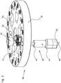
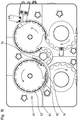
- a simulated cigarette part reorienting device 10 for reorienting simulated cigarette parts 12 which are carried by a product carrier 14.
- the simulated cigarette parts 12 are reoriented about a vertical product axis 16 from a first angular orientation 18 to a second, predetermined orientation 20 relative to said product carrier.
- the product carriers carrying the parts are transported along a track starting at entrance 90 and ending at exit 92.
- the product carriers are guided by the conveyors 94, 96, 97 and 98 in the direction indicated by the arrows 91.
- the reorienting device is located downstream from conveyor 97 and upstream from conveyor 98.
- the tracks are supported by the track support frame 100.
- the reorienting device has a first cam track 22 (shown in figure 2 ) extending around a main vertical rotation axis 24 and having a varying radius R.
- the cam track is supported by a cam track support 34. Due to the varying radius R, cams 52 following the cam track move radially during the rotary movement of a rotary carrousel 30.
- the rotary carrousel rotates about the main vertical rotation axis and comprises a rotary support frame 32 configured to rotate about the main vertical rotation axis.
- the first cam track 22 has a varying radius R relative to the main vertical rotation axis 24.
- the varying radius R causes a radial movement of the cam 52 when the cam travels along the first cam track during the rotary movement of the rotary carrousel.
- the first cam track is also endless and extends in a plane substantially perpendicular to the main vertical rotation axis 24.
- a second cam track 70 is provided around a trajectory of the circular track 62.
- the second cam track 70 induces a vertical displacement of the first section of the reorienting units 40.
- Both the first cam track 22 and the second cam track are stationary.
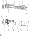
- Figure 3 shows the rotary carrousel 30.
- a plurality of reorienting units 40 are connected to the rotary support frame 32. Although only one reorienting unit is shown, the skilled person will understand that the invention comprises a plurality of reorienting units. They are arranged in a circular configuration when viewed in top view. Each reorienting unit 40 projects downward from the rotary support frame through an opening in the rotary support frame.
- Each reorienting unit 40 is constructed with a second section 45 which is fixed in vertical direction relative to the rotary support frame 32.
- the rotary carrousel 30 further comprises a plurality of transmission mechanisms 50 connected to the rotary support frame 32.
- Figure 3 only shows one transmission mechanism, but the skilled person will understand that the invention discloses a plurality of transmission mechanisms.
- Each transmission mechanism is associated with a reorienting unit 40.
- the transmission mechanism comprises a cam 52 which moves along the first cam track 22 during the rotation of the rotary support frame.
- the transmission mechanism converts a movement of the cam into a rotation of the first section 44 of the reorienting unit about the vertical unit axis relative to the rotary support frame.
- the transmission mechanism 50 as shown in figure 3 and 5 comprises a transmission gear 54 which is attached to the cam 52.
- Each reorienting unit comprises an actuating gear 41 which extends around the unit axis and engages the transmission gear of the transmission mechanism. A radial movement of the cam results in a movement of the transmission gear. This will result in turn in a movement of the actuating gear.
- each reorienting unit 40 consists of an engagement member 42 which engages the simulated cigarette part.
- the engagement member may comprise a protrusion 80 and/or a recess. After engaging the simulated cigarette part, the engagement member reorients it about the vertical product axis 16 relative to the product carrier.
- the reorienting unit itself comprises a first section 44 that rotates about a vertical unit axis 46 relative to the rotary support frame. The first section can move in a vertical direction between an upper position 48 and a lower position 49. The upper position is a retracted position and the lower position is an engagement position.
- Each engagement member 42 is provided at the lower end of the respective reorienting unit 40.
- the first section of the reorienting unit comprises the said engagement member.
- An upper side of the simulated cigarette parts comprises a mating shape. This may be a protrusion or a recess, or a combination. In case of a recess, the engagement member comprises a mating protrusion 80. The protrusion then engages and fit in the mating shape of the simulated cigarette part during operation.
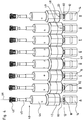
- Figure 4 shows a schematic view of the vertical movement of the first section, wherein figures 4A and 4H depict the upper position and figures 4D-4G depict the lower, engagement position.
- figures 4A and 4H depict the upper position
- figures 4D-4G depict the lower, engagement position.
- the first section is also engaged, but not in its lower position.
- the reorienting units are configured in a circular manner instead of the linear representation of figure 4 .
- Figure 4A shows the reorienting unit 40 in the upper position 48.
- Figure 4B shows the engagement member 42, the protrusion 80 in contact with the upper side of the simulated cigarette part. From figure 4B to figure 4C , the protrusion slides over the upper side of the part carried by the product carrier in a rotary manner. The protrusion keeps on rotating and sliding over the upper side until the protrusion is positioned exactly above the mating shape 82, in this case a recess.
- the resilient member 47 ( figure 5 ) forces the protrusion into the mating shape. This is shown in figure 4D and the first section 44 of the reorienting unit is in the lower position 49.
- Figures 11A-11D show more generally a first mating part 81 provided on the engagement member 42.
- the first mating part 81 is a protruding part
- the first mating part 81 in figure 11B is a recess. Both configurations are possible, as long as the simulated cigarette part has a second mating part 83 at an upper side thereof which mates with the first mating part. If the first mating part 81 is protruding, then the second mating part 83 has at least a recess to accommodate the protruding part of the fist mating part 81, or vice versa.
- Figure 11A further shows the first mating shape 81 comprising a male or female centering part 84 configured to concentrically align the engagement member with the simulated cigarette part. This speeds up the engagement of the engagement member with the simulated cigarette part. It also increases the reliability.
- a center 85 of the first mating shape is located on the vertical unit axis 46.
- the centering part 84 protrudes beyond one or more side protrusions 86, in the shown embodiment beyond two side protrusions 86.
- the side protrusions 86 extend radially outward from the vertical unit axis 46.
- the male or female centering part is conical.
- Figures 4D to 4G show the reorienting of the simulated cigarette part.
- Figure 4G also shows the second, predetermined orientation 20 of the part carried by the product carrier. With the part in the second, predetermined orientation, the reorienting unit arrives upstream from the upward slope section 72 of the second cam track 70, see figure 1 . Due to the upward slope section the engagement member moves upwards and disengages the simulated cigarette part. This is shown in figure 4H . At this stage the part is in the second, predetermined orientation and the first section of the reorienting unit is in the upper position.
- the reorienting unit 40 comprises a first section 44 which moves between an upper position 48 and a lower position 49.
- a resilient member 47 in the form of a helical spring is provided in the reorienting unit and vertically displaces the first section and biases the first section in a downward direction.
- the resilient member acts on a second section 45 of the reorienting unit.
- the second section is fixed in the direction of a vertical unit axis 46.
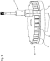
- the reorienting device further comprises a moving device 60 for moving the product carriers.
- the moving device consists of a circular track 62 that is located underneath the reorienting units 40 and guides the product carriers 14 holding the simulated cigarette parts.
- the moving device comprises a plurality of product carrier movers 64 which move the product carriers along the said circular track underneath the reorienting units.
- the product carrier movers 64 are provided in a body which resembles a gear.
- the product carriers are supported by the circular track 62 and are only pushed forward in a horizontal direction by the moving device.
- the product carrier movers 64 maintain the angular position of the product carriers during the reorientation of the simulated cigarette part.
- the simulated cigarette parts are held by the product carriers.
- the second cam track 70 as shown in figure 8 consists of an upward slope 72, a substantially horizontal section 76 and a downward slope section 74.
- the reorienting units arrive at an upstream end of the upward slope section in the lower position 49 and in an engaged state with a simulated cigarette part. Subsequently, the reorienting units engage the upward slope section and are displaced upwards by the upward slope section. This causes a disengagement of the reorienting units from the simulated cigarette parts.
- the reorienting units are then guided over the substantially horizontal section located downstream from the upward slope section and upstream from the downward slope section.
- the first section of the reorienting units are in the upper position.
- the first section of the reorienting units is vertically displaced in a downward direction as it travels along the downward slope section. This makes it possible to engage the first section of each reorienting unit with a next simulated cigarette part.
- the first cam track 22 extends in a plane which is substantially perpendicular to the main vertical rotation axis 24.
- the first cam track may be also stationary and/or endless.
- the second cam track is also stationary. However, the second cam track extends along a part of a trajectory of the reorienting units.
- the rotary carrousel is intended to make a continuous movement in particular a rotary movement. This has the advantage of a high production rate.
- step e) comprises pressing the protrusion into a recess of the simulated cigarette part.
- the pressing is achieved due to the force of the resilient member. Thereby the lowest position of the first section of the reorienting unit is reached.
- the engagement member has a recess and the simulated cigarette part has a protrusion, a skilled person will understand the recess is pressed over the protrusion.
- the first angular orientation of the simulated cigarette parts is arbitrary.
- the engagement member engages the simulated cigarette part carried by a product carrier. After engaging, the simulated cigarette part is rotated relative to the product carrier. So the following steps are carried out:
- the first section of the reorienting units is displaced vertically.
Landscapes
- Engineering & Computer Science (AREA)
- Mechanical Engineering (AREA)
- Wrapping Of Specific Fragile Articles (AREA)
- Specific Conveyance Elements (AREA)
- Manufacturing Of Cigar And Cigarette Tobacco (AREA)
Claims (15)
- Neuorientierungsvorrichtung (10) zum Neuorientieren simulierter Zigarettenteile (12), die durch einen Produktträger (14) geführt werden, um eine vertikale Produktachse (16) von einer ersten Winkelorientierung (18) in eine zweite vorgegebenen Orientierung (20) in Bezug auf den Produktträger, wobei die Vorrichtung Folgendes umfasst:- eine vertikale Hauptrotationsachse (24);- eine erste Nockenbahn (22), die mindestens teilweise um die vertikale Hauptrotationsachse (24) verläuft;- ein Drehkarussell (30), das konfiguriert ist, sich um die vertikale Hauptdrehachse zu drehen, wobei das Drehkarussell Folgendes umfasst:∘ einen drehenden Tragrahmen (32);∘ mehrere Neuorientierungseinheiten (40), die mit dem drehenden Tragrahmen verbunden sind und in einer Draufsicht in einer kreisförmigen Konfiguration angeordnet sind, wobei jede Neuorientierungseinheit ein Eingriffselement (42) umfasst, jedes Eingriffselement konfiguriert ist, mit dem simulierten Zigarettenteil in Eingriff zu sein und ihn um eine vertikale Produktachse neu zu orientieren, jede Neuorientierungseinheit einen ersten Abschnitt (44) umfasst, der in Bezug auf den drehbaren Tragrahmen um eine vertikale Einheitsachse (46) drehbar ist und in einer Vertikalrichtung zwischen einer oberen Stellung (48) und einer unteren Stellung (49) beweglich ist, die obere Stellung eine eingezogene Stellung ist und die untere Stellung eine Eingriffsstellung ist; und∘ mehrere Übertragungsmechanismen (50), die mit dem drehenden Tragrahmen verbunden sind, wobei jeder Übertragungsmechanismus mit einer entsprechenden Neuorientierungseinheit verbunden ist, jeder Übertragungsmechanismus einen Nocken (52) umfasst, der sich während der Drehung des drehenden Tragrahmens entlang der ersten Nockenbahn bewegt, und die Übertragungsmechanismen eine Bewegung des Nockens in eine Drehung des ersten Abschnitts der Neuorientierungseinheit um die vertikale Einheitsachse in Bezug auf den drehenden Tragrahmen umwandeln;- eine Bewegungsvorrichtung (60) zum Bewegen der Produktträger, wobei die Bewegungsvorrichtung Folgendes umfasst:∘ eine kreisförmige Bahn (62), die sich unter den Neuorientierungseinheiten befindet und konfiguriert ist, die Produktträger, die die simulierten Zigarettenteile halten, zu leiten; und∘ mehrere Produktträgerbewegungseinrichtungen (64) zum Bewegen der Produktträger entlang der kreisförmigen Bahn unter den Neuorientierungseinheiten, und- eine zweite Nockenbahn (70), die konfiguriert ist, den ersten Abschnitt der Neuorientierungseinheiten vertikal zu versetzen.
- Neuorientierungsvorrichtung nach Anspruch 1, wobei die Neuorientierungseinheit Folgendes umfasst:- den ersten Abschnitt (44), der zwischen einer oberen Stellung und einer unteren Stellung beweglich ist, und einen zweiten Abschnitt (45), der in einer Richtung der vertikalen Einheitsachse fest ist; und- ein elastisches Element (47), das konfiguriert ist, den ersten Abschnitt vertikal zu versetzen und den ersten Abschnitt in einer Abwärtsrichtung vorzubelasten.
- Neuorientierungsvorrichtung nach einem der vorhergehenden Ansprüche, wobei die erste Nockenbahn einen in Bezug auf die Hauptdrehachse variierenden Radius (R) besitzt, der konfiguriert ist, eine Radialbewegung des Nockens zu bewirken, wenn der Nocken sich während der Drehbewegung des Drehkarussells entlang der ersten Nockenbahn bewegt.
- Neuorientierungsvorrichtung nach einem der vorhergehenden Ansprüche, wobei jeder Übertragungsmechanismus ein Übertragungszahnrad (54) umfasst, das am Nocken angebracht ist, und wobei jede Neuorientierungseinheit ein Betätigungszahnrad (41) umfasst, das um die Einheitsachse verläuft und mit dem Übertragungszahnrad (54) des Übertragungsmechanismus in Eingriff ist.
- Neuorientierungsvorrichtung nach Anspruch 4, wobei eine Radialbewegung des Nockens in einer Bewegung des Übertragungszahnrads resultiert und wiederum in einer Bewegung des Betätigungszahnrads resultiert.
- Neuorientierungsvorrichtung nach einem der vorhergehenden Ansprüche, wobei die zweite Nockenbahn (70) Folgendes umfasst:- einen Aufwärtsneigungsabschnitt (72), wobei jede Neuorientierungseinheit konfiguriert ist, bei einem stromaufseitigen Ende des Aufwärtsneigungsabschnitts in einer unteren Stellung und in einem in Eingriff befindlichen Zustand mit dem simulierten Zigarettenteil anzukommen, und die Neuorientierungseinheiten konfiguriert sind, mit dem Aufwärtsneigungsabschnitt in Eingriff zu gelangen, und über den Aufwärtsneigungsabschnitt nach oben bewegt werden, wodurch ein Lösen der Neuorientierungseinheiten vom simulierten Zigarettenteil bewirkt wird; und- einen Abwärtsneigungsabschnitt (74), der sich stromabwärts des Aufwärtsneigungsabschnitts befindet, wobei der Abwärtsneigungsabschnitt konfiguriert ist, den ersten Abschnitt jeder Neuorientierungseinheit in einer Abwärtsrichtung zu versetzen, um den ersten Abschnitt jeder Neuorientierungseinheit mit einem nächsten simulierten Zigarettenteil in Eingriff zu bringen.
- Neuorientierungsvorrichtung nach einem der vorhergehenden Ansprüche, wobei die erste und die zweite Nockenbahn ortsfest sind.
- Neuorientierungsvorrichtung nach einem der vorhergehenden Ansprüche, wobei das Drehkarussell konfiguriert ist, eine kontinuierliche Bewegung, insbesondere eine Drehbewegung vorzunehmen.
- Neuorientierungsvorrichtung nach einem der vorhergehenden Ansprüche, wobei der erste Abschnitt das Eingriffselement umfasst, das einen ersten Verbindungsteil (81) umfasst, der konfiguriert ist, mit einem zweiten Verbindungsteil (83), der auf der Oberseite des simulierten Zigarettenteils vorgesehen ist, in Eingriff zu sein.
- Neuorientierungsvorrichtung nach dem vorhergehenden Anspruch, wobei der erste Verbindungsteil einen Bolzen- oder Buchsen-Zentrierteil (84) umfasst, der konfiguriert ist, das Eingriffselement auf den simulierten Zigarettenteil konzentrisch auszurichten, ein Zentrum (85) des ersten Verbindungsteils sich auf der vertikalen Einheitsachse (46) befindet und der Zentrierteil über einen oder mehrere Seitenüberstände (86) vorsteht, wobei ein oder mehrere Seitenüberstände von der vertikalen Einheitsachse (46) radial nach außen verlaufen.
- Neuorientierungsvorrichtung nach dem vorhergehenden Anspruch, wobei der Bolzen- oder Buchsen-Zentrierteil konisch ist.
- Neuorientierungsvorrichtung nach einem der Ansprüche 9-11, wobei der erste Abschnitt das Eingriffselement umfasst, das einen Überstand (80) umfasst, der konfiguriert ist, mit der Verbindungsform (82), die in der Oberseite des simulierten Zigarettenteils vorgesehen ist, in Eingriff zu sein.
- Neuorientierungsvorrichtung nach einem der vorhergehenden Ansprüche, wobei die erste Winkelorientierung der simulierten Zigarettenteile beliebig ist und das Eingriffselement konfiguriert ist,- mit dem simulierten Zigarettenteil in Eingriff zu gelangen,- über die Oberfläche des simulierten Zigarettenteils in einer drehenden Weise zu gleiten, bis es in oder über die Verbindungsform des simulierten Zigarettenteils passt,- anschließend durch die Kraft des elastischen Elements in oder über die Verbindungsform gepresst zu werden und- anschließend den simulierten Zigarettenteil in Bezug auf den Produktträger zu drehen.
- Neuorientierungsvorrichtung nach einem der vorhergehenden Ansprüche, wobei die Produktträgerbewegungseinrichtungen derart konstruiert sind, dass sie die Winkelstellung der Produktträger beibehalten, wenn die simulierten Zigarettenteile, die durch die Produktträger gehalten werden, neu orientiert werden.
- Verfahren zum Neuorientieren simulierter Zigarettenteile, wobei das Verfahren Folgendes umfasst:- Einspeisen von Produktträgern in die Bahn der Neuorientierungsvorrichtung gemäß einem der vorhergehenden Ansprüche und Bewegen der Produktträger entlang der Bahn, wobei jeder Produktträger einen simulierten Zigarettenteil führt;- in Eingriff Bringen des simulierten Zigarettenteils mit dem Eingriffselement des ersten Abschnitts einer Neuorientierungseinheit durch eine Abwärtsbewegung des ersten Abschnitts der Neuorientierungseinheit; und- Drehen des simulierten Zigarettenteils in Bezug auf den Produktträger durch eine Drehbewegung der Neuorientierungseinheit zur zweiten vorgegebenen Orientierung.
Priority Applications (1)
| Application Number | Priority Date | Filing Date | Title |
|---|---|---|---|
| PL17754813T PL3487329T3 (pl) | 2016-07-20 | 2017-07-18 | Urządzenie zmieniające orientację części symulowanego papierosa |
Applications Claiming Priority (2)
| Application Number | Priority Date | Filing Date | Title |
|---|---|---|---|
| NL2017196A NL2017196B1 (en) | 2016-07-20 | 2016-07-20 | Simulated cigarette parts reorienting apparatus |
| PCT/NL2017/050484 WO2018016950A1 (en) | 2016-07-20 | 2017-07-18 | Simulated cigarette parts reorienting apparatus |
Publications (2)
| Publication Number | Publication Date |
|---|---|
| EP3487329A1 EP3487329A1 (de) | 2019-05-29 |
| EP3487329B1 true EP3487329B1 (de) | 2020-09-02 |
Family
ID=56852374
Family Applications (1)
| Application Number | Title | Priority Date | Filing Date |
|---|---|---|---|
| EP17754813.8A Active EP3487329B1 (de) | 2016-07-20 | 2017-07-18 | Vorrichtung zur neuausrichtung simulierter zigarettenteile |
Country Status (7)
| Country | Link |
|---|---|
| US (1) | US10583997B2 (de) |
| EP (1) | EP3487329B1 (de) |
| JP (1) | JP6929348B2 (de) |
| ES (1) | ES2836288T3 (de) |
| NL (1) | NL2017196B1 (de) |
| PL (1) | PL3487329T3 (de) |
| WO (1) | WO2018016950A1 (de) |
Families Citing this family (3)
| Publication number | Priority date | Publication date | Assignee | Title |
|---|---|---|---|---|
| PL3823478T3 (pl) * | 2018-07-19 | 2023-05-22 | Sluis Cigar Machinery B.V. | Układ do wykonywania etapu przetwarzania na częściach urządzenia symulowanych urządzeń do palenia, takich jak papierosy elektroniczne |
| CN109759345A (zh) * | 2019-02-25 | 2019-05-17 | 深圳市卓茂科技有限公司 | 一种x-ray检测设备 |
| DE102020104063B4 (de) * | 2020-02-17 | 2023-01-19 | Romaco Kilian Gmbh | Fördervorrichtung für vereinzelte Erzeugnisse |
Citations (23)
| Publication number | Priority date | Publication date | Assignee | Title |
|---|---|---|---|---|
| US3119482A (en) | 1960-08-03 | 1964-01-28 | Continental Can Co | Method and machine for positioning articles to be packaged |
| DE2362727A1 (de) | 1972-12-18 | 1974-06-20 | Azionaria Costruzioni | Vorrichtung zum anordnen von gegenstaenden, die ungeordnet auf einem abgabefoerderer ankommen, in einer vorbestimmten folge auf einem aufnahmefoerderer |
| US4656817A (en) | 1986-01-10 | 1987-04-14 | Advalloy, Inc. | Apparatus for loading singulated lead frames into containers |
| DE3728291A1 (de) | 1987-08-25 | 1989-03-09 | Wilhelm Goetz | Verfahren und vorrichtung zum anordnen und halten einer mehrzahl packungseinheiten in einem gemeinsamen aufnahmebehaelter |
| DE4102028A1 (de) | 1990-03-07 | 1991-09-12 | Cavanna Spa | Foerdereinrichtung |
| EP0486439B1 (de) | 1990-11-14 | 1994-03-02 | Maurizio Marchesini | Anordnung zum synchronen Antrieb von Einrichtungen zur Füllung und Containerbehandlung in Getränkeabfüllern |
| EP0486440B1 (de) | 1990-11-14 | 1994-06-08 | Maurizio Marchesini | Vorrichtung zum Ausgeben von flüssigen Produkten zu drehbeweglichen Teilen, insbesondere für Getränkeabfüller |
| US5581975A (en) | 1993-12-24 | 1996-12-10 | I.M.A. Industria Macchine Automatiche S.P.A. | Automatic machine for filling and closing flasks or the like containers |
| DE69720078T2 (de) | 1996-09-11 | 2004-04-01 | Pure Technology of St. Cloud, Inc., St. Cloud | Verfahren und vorrichtung zum überführen von gegenständen von einem eimer oder förderer auf ein aufnahmeband |
| DE69819089T2 (de) | 1997-08-05 | 2004-07-22 | Azionaria Costruzioni Macchine Automatiche A.C.M.A. S.P.A. | Förderanlage zum Transport von Gütern |
| US6779651B1 (en) | 1999-12-13 | 2004-08-24 | Sidel | Device for conveying discrete entities having an improved transfer arm, and container blow-molding facility with such a device |
| DE60009594T2 (de) | 1999-04-29 | 2005-04-14 | Klöckner Hänsel Tevopharm B.V. | Drehbare Greifvorrichtung |
| US20050103399A1 (en) | 2003-09-30 | 2005-05-19 | Volker Till | Beverage bottling plant for filling bottles with a liquid beverage filling material, having a transfer device for the transfer of containers from a transfer starwheel to the carousel of a container handling machine |
| DE202005006755U1 (de) | 2005-04-26 | 2005-10-20 | Khs Maschinen- Und Anlagenbau Ag | Vorrichtung zur Verschlussausrichtung |
| EP1460028B1 (de) | 2003-03-19 | 2006-09-06 | Luciano Salda | Rotationssterilisator und -füller |
| EP1889802A2 (de) | 2006-08-14 | 2008-02-20 | Neri S.p.A. | Karussell-Vorrichtung zur Beförderung von Containern |
| US20090095371A1 (en) | 2003-11-10 | 2009-04-16 | Alois Monzel | Method of filling kegs with a liquid beverage in a keg filling plant |
| DE102009005180A1 (de) | 2009-01-15 | 2010-07-22 | Khs Ag | Behälterbehandlungsmaschine |
| WO2012077147A1 (en) | 2010-12-10 | 2012-06-14 | Sidel S.P.A. | Article -handling machine |
| EP2465814A1 (de) | 2010-12-16 | 2012-06-20 | Krones AG | Vorrichtung zum Behandeln von Behältnissen mit Behältnisausrichtung |
| US20150083550A1 (en) | 2013-09-20 | 2015-03-26 | Morrison Timing Screw Co., dba Morrison Container Handling Solutions, Inc. | Rotary orienter |
| EP3012086A1 (de) | 2013-06-21 | 2016-04-27 | Nissei Asb Machine Co., Ltd. | Dynamische fördervorrichtung |
| WO2016105191A1 (en) | 2014-12-23 | 2016-06-30 | Sluis Cigar Machinery B.V. | Device for filling cartridges of e-cigarettes with a liquid |
Family Cites Families (7)
| Publication number | Priority date | Publication date | Assignee | Title |
|---|---|---|---|---|
| US4174775A (en) * | 1977-04-20 | 1979-11-20 | Eli Lilly And Company | Apparatus for continuously orienting plastic and other types of bottles |
| DE4019031C2 (de) * | 1990-06-14 | 1996-08-01 | Tetra Pak Gmbh | Vorrichtung zum Verdrehen von mittels einer Fördereinrichtung tranportierten Werkstückträgern mit Werkstücken und Verwendung einer solchen Vorrichtung |
| US8136651B2 (en) * | 2007-12-14 | 2012-03-20 | The Procter & Gamble Company | Method and apparatus for orienting articles |
| ES2836904T3 (es) * | 2014-05-21 | 2021-06-28 | Sacmi Verona Spa | Carrusel para el tratamiento de contenedores |
| EP3209571B2 (de) * | 2014-11-27 | 2022-02-23 | Makro Labelling S.r.l. | Maschine und verfahren zur ausrichtung von behältern |
| DE202017105383U1 (de) * | 2016-09-19 | 2017-09-18 | Ct Pack S.R.L. | Übergabeeinheit zum Überführen von Artikeln zwischen zwei winklig zueinander angeordneten Linien |
| WO2018085830A2 (en) * | 2016-11-07 | 2018-05-11 | R. A Jones & Co. | Apparatus and methods for product orientation and hole healing applications |
-
2016
- 2016-07-20 NL NL2017196A patent/NL2017196B1/en not_active IP Right Cessation
-
2017
- 2017-07-18 US US16/317,878 patent/US10583997B2/en not_active Expired - Fee Related
- 2017-07-18 JP JP2019502249A patent/JP6929348B2/ja active Active
- 2017-07-18 EP EP17754813.8A patent/EP3487329B1/de active Active
- 2017-07-18 WO PCT/NL2017/050484 patent/WO2018016950A1/en unknown
- 2017-07-18 PL PL17754813T patent/PL3487329T3/pl unknown
- 2017-07-18 ES ES17754813T patent/ES2836288T3/es active Active
Patent Citations (23)
| Publication number | Priority date | Publication date | Assignee | Title |
|---|---|---|---|---|
| US3119482A (en) | 1960-08-03 | 1964-01-28 | Continental Can Co | Method and machine for positioning articles to be packaged |
| DE2362727A1 (de) | 1972-12-18 | 1974-06-20 | Azionaria Costruzioni | Vorrichtung zum anordnen von gegenstaenden, die ungeordnet auf einem abgabefoerderer ankommen, in einer vorbestimmten folge auf einem aufnahmefoerderer |
| US4656817A (en) | 1986-01-10 | 1987-04-14 | Advalloy, Inc. | Apparatus for loading singulated lead frames into containers |
| DE3728291A1 (de) | 1987-08-25 | 1989-03-09 | Wilhelm Goetz | Verfahren und vorrichtung zum anordnen und halten einer mehrzahl packungseinheiten in einem gemeinsamen aufnahmebehaelter |
| DE4102028A1 (de) | 1990-03-07 | 1991-09-12 | Cavanna Spa | Foerdereinrichtung |
| EP0486439B1 (de) | 1990-11-14 | 1994-03-02 | Maurizio Marchesini | Anordnung zum synchronen Antrieb von Einrichtungen zur Füllung und Containerbehandlung in Getränkeabfüllern |
| EP0486440B1 (de) | 1990-11-14 | 1994-06-08 | Maurizio Marchesini | Vorrichtung zum Ausgeben von flüssigen Produkten zu drehbeweglichen Teilen, insbesondere für Getränkeabfüller |
| US5581975A (en) | 1993-12-24 | 1996-12-10 | I.M.A. Industria Macchine Automatiche S.P.A. | Automatic machine for filling and closing flasks or the like containers |
| DE69720078T2 (de) | 1996-09-11 | 2004-04-01 | Pure Technology of St. Cloud, Inc., St. Cloud | Verfahren und vorrichtung zum überführen von gegenständen von einem eimer oder förderer auf ein aufnahmeband |
| DE69819089T2 (de) | 1997-08-05 | 2004-07-22 | Azionaria Costruzioni Macchine Automatiche A.C.M.A. S.P.A. | Förderanlage zum Transport von Gütern |
| DE60009594T2 (de) | 1999-04-29 | 2005-04-14 | Klöckner Hänsel Tevopharm B.V. | Drehbare Greifvorrichtung |
| US6779651B1 (en) | 1999-12-13 | 2004-08-24 | Sidel | Device for conveying discrete entities having an improved transfer arm, and container blow-molding facility with such a device |
| EP1460028B1 (de) | 2003-03-19 | 2006-09-06 | Luciano Salda | Rotationssterilisator und -füller |
| US20050103399A1 (en) | 2003-09-30 | 2005-05-19 | Volker Till | Beverage bottling plant for filling bottles with a liquid beverage filling material, having a transfer device for the transfer of containers from a transfer starwheel to the carousel of a container handling machine |
| US20090095371A1 (en) | 2003-11-10 | 2009-04-16 | Alois Monzel | Method of filling kegs with a liquid beverage in a keg filling plant |
| DE202005006755U1 (de) | 2005-04-26 | 2005-10-20 | Khs Maschinen- Und Anlagenbau Ag | Vorrichtung zur Verschlussausrichtung |
| EP1889802A2 (de) | 2006-08-14 | 2008-02-20 | Neri S.p.A. | Karussell-Vorrichtung zur Beförderung von Containern |
| DE102009005180A1 (de) | 2009-01-15 | 2010-07-22 | Khs Ag | Behälterbehandlungsmaschine |
| WO2012077147A1 (en) | 2010-12-10 | 2012-06-14 | Sidel S.P.A. | Article -handling machine |
| EP2465814A1 (de) | 2010-12-16 | 2012-06-20 | Krones AG | Vorrichtung zum Behandeln von Behältnissen mit Behältnisausrichtung |
| EP3012086A1 (de) | 2013-06-21 | 2016-04-27 | Nissei Asb Machine Co., Ltd. | Dynamische fördervorrichtung |
| US20150083550A1 (en) | 2013-09-20 | 2015-03-26 | Morrison Timing Screw Co., dba Morrison Container Handling Solutions, Inc. | Rotary orienter |
| WO2016105191A1 (en) | 2014-12-23 | 2016-06-30 | Sluis Cigar Machinery B.V. | Device for filling cartridges of e-cigarettes with a liquid |
Also Published As
| Publication number | Publication date |
|---|---|
| NL2017196B1 (en) | 2018-01-26 |
| US20190152717A1 (en) | 2019-05-23 |
| JP6929348B2 (ja) | 2021-09-01 |
| JP2019524102A (ja) | 2019-09-05 |
| EP3487329A1 (de) | 2019-05-29 |
| WO2018016950A1 (en) | 2018-01-25 |
| PL3487329T3 (pl) | 2021-04-19 |
| ES2836288T3 (es) | 2021-06-24 |
| US10583997B2 (en) | 2020-03-10 |
Similar Documents
| Publication | Publication Date | Title |
|---|---|---|
| EP3487329B1 (de) | Vorrichtung zur neuausrichtung simulierter zigarettenteile | |
| JP6032418B2 (ja) | リニア搬送装置 | |
| CN113260585B (zh) | 用于对容器进行分组的装置 | |
| EP2499069A1 (de) | Sortiermaschine für behälter und zugehöriges verfahren | |
| US20100200362A1 (en) | Device for loading containers on a transporting element provided with means for ejecting incorrectly loaded containers | |
| CN116194372A (zh) | 对容器进行分组的系统和方法 | |
| EP3549744B1 (de) | Ofen für vorformen | |
| US3551993A (en) | Machine and method for handling workpieces | |
| JP2011105396A (ja) | 物品搬送装置 | |
| CN116209629A (zh) | 使用多个抓持器平稳交接容器 | |
| EP2846756B1 (de) | Vorrichtung zum befüllen von kapseln | |
| US3336723A (en) | Machine for assembling containers with clips | |
| US10065805B2 (en) | Molded article supply apparatus | |
| GB2168942A (en) | Machine for placing sleeves around objects of elongate form | |
| CN113478194B (zh) | 一种连体盖高速合盖机 | |
| WO2018016953A2 (en) | Product carrier | |
| CN116194394A (zh) | 适用于各种容器周长的对容器进行分组的输送机系统 | |
| CN109367850B (zh) | 一种杯装饮品压盖机 | |
| GB1297572A (de) | ||
| EP3037356B1 (de) | Vorrichtung zum Formen eines Bodens eines Behälters | |
| CN216035341U (zh) | 一种用于饮料包装的分瓶机构 | |
| EP2377763A1 (de) | Vorrichtung und Verfahren zum Wenden von Eiern | |
| US20170291778A1 (en) | Device and method for stacking articles | |
| JP2016003125A (ja) | 物品整列装置 | |
| CN113772155A (zh) | 一种用于饮料包装的分瓶机构及分瓶方法 |
Legal Events
| Date | Code | Title | Description |
|---|---|---|---|
| STAA | Information on the status of an ep patent application or granted ep patent |
Free format text: STATUS: UNKNOWN |
|
| STAA | Information on the status of an ep patent application or granted ep patent |
Free format text: STATUS: THE INTERNATIONAL PUBLICATION HAS BEEN MADE |
|
| PUAI | Public reference made under article 153(3) epc to a published international application that has entered the european phase |
Free format text: ORIGINAL CODE: 0009012 |
|
| STAA | Information on the status of an ep patent application or granted ep patent |
Free format text: STATUS: REQUEST FOR EXAMINATION WAS MADE |
|
| 17P | Request for examination filed |
Effective date: 20190118 |
|
| AK | Designated contracting states |
Kind code of ref document: A1 Designated state(s): AL AT BE BG CH CY CZ DE DK EE ES FI FR GB GR HR HU IE IS IT LI LT LU LV MC MK MT NL NO PL PT RO RS SE SI SK SM TR |
|
| AX | Request for extension of the european patent |
Extension state: BA ME |
|
| DAV | Request for validation of the european patent (deleted) | ||
| DAX | Request for extension of the european patent (deleted) | ||
| REG | Reference to a national code |
Ref country code: DE Ref legal event code: R079 Ref document number: 602017022896 Country of ref document: DE Free format text: PREVIOUS MAIN CLASS: A24F0047000000 Ipc: A24F0040700000 |
|
| GRAP | Despatch of communication of intention to grant a patent |
Free format text: ORIGINAL CODE: EPIDOSNIGR1 |
|
| STAA | Information on the status of an ep patent application or granted ep patent |
Free format text: STATUS: GRANT OF PATENT IS INTENDED |
|
| RIC1 | Information provided on ipc code assigned before grant |
Ipc: A24F 40/70 20200101AFI20200130BHEP |
|
| INTG | Intention to grant announced |
Effective date: 20200221 |
|
| GRAS | Grant fee paid |
Free format text: ORIGINAL CODE: EPIDOSNIGR3 |
|
| GRAA | (expected) grant |
Free format text: ORIGINAL CODE: 0009210 |
|
| STAA | Information on the status of an ep patent application or granted ep patent |
Free format text: STATUS: THE PATENT HAS BEEN GRANTED |
|
| AK | Designated contracting states |
Kind code of ref document: B1 Designated state(s): AL AT BE BG CH CY CZ DE DK EE ES FI FR GB GR HR HU IE IS IT LI LT LU LV MC MK MT NL NO PL PT RO RS SE SI SK SM TR |
|
| REG | Reference to a national code |
Ref country code: GB Ref legal event code: FG4D |
|
| REG | Reference to a national code |
Ref country code: AT Ref legal event code: REF Ref document number: 1307760 Country of ref document: AT Kind code of ref document: T Effective date: 20200915 Ref country code: CH Ref legal event code: EP |
|
| REG | Reference to a national code |
Ref country code: DE Ref legal event code: R096 Ref document number: 602017022896 Country of ref document: DE |
|
| REG | Reference to a national code |
Ref country code: IE Ref legal event code: FG4D |
|
| REG | Reference to a national code |
Ref country code: LT Ref legal event code: MG4D |
|
| PG25 | Lapsed in a contracting state [announced via postgrant information from national office to epo] |
Ref country code: SE Free format text: LAPSE BECAUSE OF FAILURE TO SUBMIT A TRANSLATION OF THE DESCRIPTION OR TO PAY THE FEE WITHIN THE PRESCRIBED TIME-LIMIT Effective date: 20200902 Ref country code: HR Free format text: LAPSE BECAUSE OF FAILURE TO SUBMIT A TRANSLATION OF THE DESCRIPTION OR TO PAY THE FEE WITHIN THE PRESCRIBED TIME-LIMIT Effective date: 20200902 Ref country code: NO Free format text: LAPSE BECAUSE OF FAILURE TO SUBMIT A TRANSLATION OF THE DESCRIPTION OR TO PAY THE FEE WITHIN THE PRESCRIBED TIME-LIMIT Effective date: 20201202 Ref country code: GR Free format text: LAPSE BECAUSE OF FAILURE TO SUBMIT A TRANSLATION OF THE DESCRIPTION OR TO PAY THE FEE WITHIN THE PRESCRIBED TIME-LIMIT Effective date: 20201203 Ref country code: FI Free format text: LAPSE BECAUSE OF FAILURE TO SUBMIT A TRANSLATION OF THE DESCRIPTION OR TO PAY THE FEE WITHIN THE PRESCRIBED TIME-LIMIT Effective date: 20200902 Ref country code: BG Free format text: LAPSE BECAUSE OF FAILURE TO SUBMIT A TRANSLATION OF THE DESCRIPTION OR TO PAY THE FEE WITHIN THE PRESCRIBED TIME-LIMIT Effective date: 20201202 Ref country code: LT Free format text: LAPSE BECAUSE OF FAILURE TO SUBMIT A TRANSLATION OF THE DESCRIPTION OR TO PAY THE FEE WITHIN THE PRESCRIBED TIME-LIMIT Effective date: 20200902 |
|
| REG | Reference to a national code |
Ref country code: NL Ref legal event code: MP Effective date: 20200902 |
|
| REG | Reference to a national code |
Ref country code: AT Ref legal event code: MK05 Ref document number: 1307760 Country of ref document: AT Kind code of ref document: T Effective date: 20200902 |
|
| PG25 | Lapsed in a contracting state [announced via postgrant information from national office to epo] |
Ref country code: LV Free format text: LAPSE BECAUSE OF FAILURE TO SUBMIT A TRANSLATION OF THE DESCRIPTION OR TO PAY THE FEE WITHIN THE PRESCRIBED TIME-LIMIT Effective date: 20200902 Ref country code: RS Free format text: LAPSE BECAUSE OF FAILURE TO SUBMIT A TRANSLATION OF THE DESCRIPTION OR TO PAY THE FEE WITHIN THE PRESCRIBED TIME-LIMIT Effective date: 20200902 |
|
| PG25 | Lapsed in a contracting state [announced via postgrant information from national office to epo] |
Ref country code: EE Free format text: LAPSE BECAUSE OF FAILURE TO SUBMIT A TRANSLATION OF THE DESCRIPTION OR TO PAY THE FEE WITHIN THE PRESCRIBED TIME-LIMIT Effective date: 20200902 Ref country code: SM Free format text: LAPSE BECAUSE OF FAILURE TO SUBMIT A TRANSLATION OF THE DESCRIPTION OR TO PAY THE FEE WITHIN THE PRESCRIBED TIME-LIMIT Effective date: 20200902 Ref country code: CZ Free format text: LAPSE BECAUSE OF FAILURE TO SUBMIT A TRANSLATION OF THE DESCRIPTION OR TO PAY THE FEE WITHIN THE PRESCRIBED TIME-LIMIT Effective date: 20200902 Ref country code: PT Free format text: LAPSE BECAUSE OF FAILURE TO SUBMIT A TRANSLATION OF THE DESCRIPTION OR TO PAY THE FEE WITHIN THE PRESCRIBED TIME-LIMIT Effective date: 20210104 Ref country code: RO Free format text: LAPSE BECAUSE OF FAILURE TO SUBMIT A TRANSLATION OF THE DESCRIPTION OR TO PAY THE FEE WITHIN THE PRESCRIBED TIME-LIMIT Effective date: 20200902 |
|
| PG25 | Lapsed in a contracting state [announced via postgrant information from national office to epo] |
Ref country code: AL Free format text: LAPSE BECAUSE OF FAILURE TO SUBMIT A TRANSLATION OF THE DESCRIPTION OR TO PAY THE FEE WITHIN THE PRESCRIBED TIME-LIMIT Effective date: 20200902 Ref country code: AT Free format text: LAPSE BECAUSE OF FAILURE TO SUBMIT A TRANSLATION OF THE DESCRIPTION OR TO PAY THE FEE WITHIN THE PRESCRIBED TIME-LIMIT Effective date: 20200902 Ref country code: IS Free format text: LAPSE BECAUSE OF FAILURE TO SUBMIT A TRANSLATION OF THE DESCRIPTION OR TO PAY THE FEE WITHIN THE PRESCRIBED TIME-LIMIT Effective date: 20210102 |
|
| REG | Reference to a national code |
Ref country code: DE Ref legal event code: R026 Ref document number: 602017022896 Country of ref document: DE |
|
| PLBI | Opposition filed |
Free format text: ORIGINAL CODE: 0009260 |
|
| PLAX | Notice of opposition and request to file observation + time limit sent |
Free format text: ORIGINAL CODE: EPIDOSNOBS2 |
|
| REG | Reference to a national code |
Ref country code: ES Ref legal event code: FG2A Ref document number: 2836288 Country of ref document: ES Kind code of ref document: T3 Effective date: 20210624 |
|
| PG25 | Lapsed in a contracting state [announced via postgrant information from national office to epo] |
Ref country code: SK Free format text: LAPSE BECAUSE OF FAILURE TO SUBMIT A TRANSLATION OF THE DESCRIPTION OR TO PAY THE FEE WITHIN THE PRESCRIBED TIME-LIMIT Effective date: 20200902 |
|
| 26 | Opposition filed |
Opponent name: SEEMANN & PARTNER PATENTANWAELTE MBB Effective date: 20210602 |
|
| PG25 | Lapsed in a contracting state [announced via postgrant information from national office to epo] |
Ref country code: SI Free format text: LAPSE BECAUSE OF FAILURE TO SUBMIT A TRANSLATION OF THE DESCRIPTION OR TO PAY THE FEE WITHIN THE PRESCRIBED TIME-LIMIT Effective date: 20200902 Ref country code: DK Free format text: LAPSE BECAUSE OF FAILURE TO SUBMIT A TRANSLATION OF THE DESCRIPTION OR TO PAY THE FEE WITHIN THE PRESCRIBED TIME-LIMIT Effective date: 20200902 |
|
| PLBB | Reply of patent proprietor to notice(s) of opposition received |
Free format text: ORIGINAL CODE: EPIDOSNOBS3 |
|
| REG | Reference to a national code |
Ref country code: CH Ref legal event code: PL |
|
| PG25 | Lapsed in a contracting state [announced via postgrant information from national office to epo] |
Ref country code: MC Free format text: LAPSE BECAUSE OF FAILURE TO SUBMIT A TRANSLATION OF THE DESCRIPTION OR TO PAY THE FEE WITHIN THE PRESCRIBED TIME-LIMIT Effective date: 20200902 |
|
| REG | Reference to a national code |
Ref country code: BE Ref legal event code: MM Effective date: 20210731 |
|
| PG25 | Lapsed in a contracting state [announced via postgrant information from national office to epo] |
Ref country code: LI Free format text: LAPSE BECAUSE OF NON-PAYMENT OF DUE FEES Effective date: 20210731 Ref country code: CH Free format text: LAPSE BECAUSE OF NON-PAYMENT OF DUE FEES Effective date: 20210731 |
|
| PG25 | Lapsed in a contracting state [announced via postgrant information from national office to epo] |
Ref country code: LU Free format text: LAPSE BECAUSE OF NON-PAYMENT OF DUE FEES Effective date: 20210718 |
|
| REG | Reference to a national code |
Ref country code: DE Ref legal event code: R100 Ref document number: 602017022896 Country of ref document: DE |
|
| PLBP | Opposition withdrawn |
Free format text: ORIGINAL CODE: 0009264 |
|
| PG25 | Lapsed in a contracting state [announced via postgrant information from national office to epo] |
Ref country code: IE Free format text: LAPSE BECAUSE OF NON-PAYMENT OF DUE FEES Effective date: 20210718 Ref country code: BE Free format text: LAPSE BECAUSE OF NON-PAYMENT OF DUE FEES Effective date: 20210731 |
|
| PLBD | Termination of opposition procedure: decision despatched |
Free format text: ORIGINAL CODE: EPIDOSNOPC1 |
|
| PGFP | Annual fee paid to national office [announced via postgrant information from national office to epo] |
Ref country code: IT Payment date: 20220728 Year of fee payment: 6 Ref country code: GB Payment date: 20220722 Year of fee payment: 6 Ref country code: DE Payment date: 20220720 Year of fee payment: 6 |
|
| PGFP | Annual fee paid to national office [announced via postgrant information from national office to epo] |
Ref country code: PL Payment date: 20220708 Year of fee payment: 6 Ref country code: FR Payment date: 20220722 Year of fee payment: 6 |
|
| PLBM | Termination of opposition procedure: date of legal effect published |
Free format text: ORIGINAL CODE: 0009276 |
|
| 27C | Opposition proceedings terminated |
Effective date: 20220712 |
|
| PGFP | Annual fee paid to national office [announced via postgrant information from national office to epo] |
Ref country code: ES Payment date: 20221020 Year of fee payment: 6 |
|
| P01 | Opt-out of the competence of the unified patent court (upc) registered |
Effective date: 20230522 |
|
| PG25 | Lapsed in a contracting state [announced via postgrant information from national office to epo] |
Ref country code: NL Free format text: LAPSE BECAUSE OF NON-PAYMENT OF DUE FEES Effective date: 20200923 Ref country code: CY Free format text: LAPSE BECAUSE OF FAILURE TO SUBMIT A TRANSLATION OF THE DESCRIPTION OR TO PAY THE FEE WITHIN THE PRESCRIBED TIME-LIMIT Effective date: 20200902 |
|
| PG25 | Lapsed in a contracting state [announced via postgrant information from national office to epo] |
Ref country code: HU Free format text: LAPSE BECAUSE OF FAILURE TO SUBMIT A TRANSLATION OF THE DESCRIPTION OR TO PAY THE FEE WITHIN THE PRESCRIBED TIME-LIMIT; INVALID AB INITIO Effective date: 20170718 |
|
| REG | Reference to a national code |
Ref country code: DE Ref legal event code: R119 Ref document number: 602017022896 Country of ref document: DE |
|
| GBPC | Gb: european patent ceased through non-payment of renewal fee |
Effective date: 20230718 |
|
| PG25 | Lapsed in a contracting state [announced via postgrant information from national office to epo] |
Ref country code: MK Free format text: LAPSE BECAUSE OF FAILURE TO SUBMIT A TRANSLATION OF THE DESCRIPTION OR TO PAY THE FEE WITHIN THE PRESCRIBED TIME-LIMIT Effective date: 20200902 Ref country code: DE Free format text: LAPSE BECAUSE OF NON-PAYMENT OF DUE FEES Effective date: 20240201 Ref country code: GB Free format text: LAPSE BECAUSE OF NON-PAYMENT OF DUE FEES Effective date: 20230718 |
|
| PG25 | Lapsed in a contracting state [announced via postgrant information from national office to epo] |
Ref country code: FR Free format text: LAPSE BECAUSE OF NON-PAYMENT OF DUE FEES Effective date: 20230731 |
|
| PG25 | Lapsed in a contracting state [announced via postgrant information from national office to epo] |
Ref country code: IT Free format text: LAPSE BECAUSE OF NON-PAYMENT OF DUE FEES Effective date: 20230718 |
|
| REG | Reference to a national code |
Ref country code: ES Ref legal event code: FD2A Effective date: 20240828 |
|
| PG25 | Lapsed in a contracting state [announced via postgrant information from national office to epo] |
Ref country code: MT Free format text: LAPSE BECAUSE OF FAILURE TO SUBMIT A TRANSLATION OF THE DESCRIPTION OR TO PAY THE FEE WITHIN THE PRESCRIBED TIME-LIMIT Effective date: 20200902 |