EP0486440B1 - Vorrichtung zum Ausgeben von flüssigen Produkten zu drehbeweglichen Teilen, insbesondere für Getränkeabfüller - Google Patents
Vorrichtung zum Ausgeben von flüssigen Produkten zu drehbeweglichen Teilen, insbesondere für Getränkeabfüller Download PDFInfo
- Publication number
- EP0486440B1 EP0486440B1 EP91830492A EP91830492A EP0486440B1 EP 0486440 B1 EP0486440 B1 EP 0486440B1 EP 91830492 A EP91830492 A EP 91830492A EP 91830492 A EP91830492 A EP 91830492A EP 0486440 B1 EP0486440 B1 EP 0486440B1
- Authority
- EP
- European Patent Office
- Prior art keywords
- carousel
- containers
- liquid
- platform
- chamber
- Prior art date
- Legal status (The legal status is an assumption and is not a legal conclusion. Google has not performed a legal analysis and makes no representation as to the accuracy of the status listed.)
- Expired - Lifetime
Links
- 239000012263 liquid product Substances 0.000 title claims description 8
- 239000007788 liquid Substances 0.000 claims description 22
- 230000000712 assembly Effects 0.000 claims description 4
- 238000000429 assembly Methods 0.000 claims description 4
- 230000004913 activation Effects 0.000 description 1
- 239000000945 filler Substances 0.000 description 1
- 239000012530 fluid Substances 0.000 description 1
- 238000012423 maintenance Methods 0.000 description 1
- 239000000463 material Substances 0.000 description 1
- 238000000034 method Methods 0.000 description 1
- 238000005406 washing Methods 0.000 description 1
Images

Classifications
-
- B—PERFORMING OPERATIONS; TRANSPORTING
- B65—CONVEYING; PACKING; STORING; HANDLING THIN OR FILAMENTARY MATERIAL
- B65B—MACHINES, APPARATUS OR DEVICES FOR, OR METHODS OF, PACKAGING ARTICLES OR MATERIALS; UNPACKING
- B65B3/00—Packaging plastic material, semiliquids, liquids or mixed solids and liquids, in individual containers or receptacles, e.g. bags, sacks, boxes, cartons, cans, or jars
- B65B3/26—Methods or devices for controlling the quantity of the material fed or filled
- B65B3/30—Methods or devices for controlling the quantity of the material fed or filled by volumetric measurement
- B65B3/32—Methods or devices for controlling the quantity of the material fed or filled by volumetric measurement by pistons co-operating with measuring chambers
- B65B3/323—Methods or devices for controlling the quantity of the material fed or filled by volumetric measurement by pistons co-operating with measuring chambers with measuring chambers travelling in an endless path
-
- B—PERFORMING OPERATIONS; TRANSPORTING
- B67—OPENING, CLOSING OR CLEANING BOTTLES, JARS OR SIMILAR CONTAINERS; LIQUID HANDLING
- B67C—CLEANING, FILLING WITH LIQUIDS OR SEMILIQUIDS, OR EMPTYING, OF BOTTLES, JARS, CANS, CASKS, BARRELS, OR SIMILAR CONTAINERS, NOT OTHERWISE PROVIDED FOR; FUNNELS
- B67C3/00—Bottling liquids or semiliquids; Filling jars or cans with liquids or semiliquids using bottling or like apparatus; Filling casks or barrels with liquids or semiliquids
- B67C3/02—Bottling liquids or semiliquids; Filling jars or cans with liquids or semiliquids using bottling or like apparatus
- B67C3/22—Details
- B67C3/28—Flow-control devices, e.g. using valves
Definitions
- the present invention relates to the technical sector of automatic machinery for filling containers with liquid products.
- a variety of automatic machines which fill containers such as bottles or vials with liquids. These machines usually have carousels or starwheels which rotate about a vertical axis and which are designed to receive the bottles to be filled in orderly fashion from a feed line.
- the carousel mounts means for dispensing the liquid product which work in synchrony with means for lining up the bottles with the corresponding nozzles of the dispensing units themselves. The filled bottles are then transferred to an outfeed line.
- the aforesaid dispensing units usually have a plurality of elements which exert a preset pressure on the liquid, and which are connected to liquid feed tubes.
- the feed tubes are connected to the liquid tank through valves mounted on the outermost edge of the carousel.
- a container filling apparatus as in the preamble of claim 1, having a plurality of revolving charging cylinders and respective pistons by which a fluid material supplied into the cylinders with their pistons at the limit end of their intake strokes is subsequently pushed out of the cylinders to fill respective containers.
- An adjusting screw is provided to set by one of its end the limit of the intake stroke of the piston rod of each piston and has a sprocket-like wheel fixed to its other end and actuated in incremental rotation by the piston rods of stationary air cylinders fixed to the apparatus frame when the wheel, revolving with its cylinders, is engaged by the piston rods.
- the activation of the air cylinders is controlled by electrical control means by which the limit of the intake stroke of any piston and, therefore, the filling quantity of the corresponding cylinder can be adjusted without danger and without stopping the operation of the apparatus.
- the object of the present invention is to provide a device which is capable of dispensing a liquid product to rotating elements and which is especially suitable for application on automatic bottle fillers.
- Another object of the invention is to provide a device that uses a simple, reliable technique and that is suitable for a wide range of bottle sizes.
- the space occupied by the claimed device is thus very limited, making for a very practical set-up, and allowing easy access to the internal parts of the carousel. Furthermore, since the structure of the device is very simple, the machine to which it is applied has added efficiency and reliability.
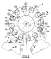
- the machine for filling bottles 1 with a liquid product has means 2 for feeding the said bottles to a carousel 3 which rotates about a vertical axis in the direction indicated by arrow A.
- Feed means 2 consist of a bottle 1 conveying line 4 along which there is an auger 5 which rotates axially in such a manner as to space the conveyed bottles 1 apart.
- Auger 5 is designed to operate in conjunction with a distributor 6, shaped like a star, for example, which rotates in the direction of arrow B.
- the bottles to be fed are held and guided by recesses 6a in distributor 6 and by ring guide 7 which partially surrounds the distributor itself.
- Carousel 3 receives bottles 1 fed by distributor 6 one by one at the point where the equally spaced grippers 8, mounted on the circumference of the carousel itself, are activated. Carousel 3 also mounts dispensing units, labelled 9 in the drawings, which fill the liquid product into bottles 1.
- a full bottle outfeed system 10 consisting of a conveyor line 11 and another distributor 12, shaped like a star, for example, which rotates in the direction of arrow C.
- the outgoing bottles are received by distributor 12 at the point where they are released by grippers 8 and are held and guided by recesses 12a in the distributor and by a ring guide 13 which partially surrounds the distributor.
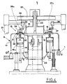
- dispensing units 9 consist of a plurality of cylinder and plunger assemblies mounted by carousel 3 which lines them up with grippers 8.
- Each of the said cylinder and plunger assemblies 14 is connected through a valve 15 to a liquid feed chamber 16 and to a filling nozzle 17 alternately.
- Chamber 16 is mounted on a platform 18 attached to the rotating part of carousel 3.
- Platform 18 is secured to the top of a vertical shaft 19, rotated continuously by the drive motor of the machine.
- Chamber 16 concentric with the axis of carousel 3, is fed through a tube 20 connected to a tank, which is not illustrated, outside the machine.
- Tube 20 is located above chamber 16, diametrically with respect to carousel 3, and is supported by a frame 21 attached to the fixed structure of the machine.
- Tube 20 is connected to a mouthpiece 22 leading out of chamber 16 in accordance with the axis of rotation of the carousel.
- valve 15 consists of a lower casing 23 fixed to carousel platform 18 and an upper casing 24 which rotates on a pin 25 about the vertical axis of valve 15 itself and in relation to fixed lower casing 23.
- Upper casing 24 has a cap 26 held by pin 25 and pushed axially by a spring 27 which presses down on casing 24.
- Lower casing 23 is crossed by a pair of parallel, vertical holes 28 and 29, which, at their bottom ends, are connected with a pair of ducts, respectively 30 and 31, made in platform 18.
- Duct 30 leads out of chamber 16, whilst duct 31 is connected to dispensing nozzle 17.
- Platform 18 is also crossed by a vertical hole 32, whose bottom end is connected to cylinder and plunger assembly 14 and whose top end extends into lower casing 23 of the valve.
- the axes of holes 28, 29 and 32 are distributed around a circle concentric with the axis of rotation of upper valve casing 24.
- Upper, rotating casing 24 is crossed by an approximately semicircular channel 33 in a horizontal plane.
- channel 33 At each end and in the middle of channel 33 there are downward opening holes 33a, 33b and 33c which serve to connect hole 32 to ducts 30 and 31 alternately, in accordance with the angular position assumed by rotating valve casing 24.
- Cap 26 of rotating casing 24 has on its top an eccentric pin 34 which rotates axially and held by a sprung bolt 35.
- Pin 34 is designed to intercept a pair of cams 36 and 37, respectively first and second cam, during the rotation of carousel 3, the said cams being carried by fixed frame 21 of the machine in diametrically opposite positions in relation to the axis of the carousel itself.
- Cams 36 and 37 have a chamfered face designed to act as a sliding guide for pin 34.
- Cams 36 and 37 are supported by actuators 38 and 39 respectively driven in a vertical direction in such a manner that they can be lifted to positions 36a and 37a in which they are disengaged from pins 34. The raising of cams 36 and 37 make it possible for washing cycles to be performed on the machine.
- valve 15 switches the connection of cylinder and plunger assembly 14 from liquid suction duct 30 to duct 31 which conveys the liquid to nozzle 17.
- eccentric pin 34 of the valve is intercepted by cam 36, thus causing upper casing 24 of the valve to rotate in relation to lower, fixed casing 23.
- channel 33 of casing 24 is connected through holes 33a and 33b to hole 32 and to duct 31, thus enabling the liquid to flow out through the nozzle.
- cam 37 intercepts eccentric pin 34, causing casing 24 of valve 15 to rotate to the initial position, that is to say, with channel 33 connected to duct 30 and cylinder and plunger assembly 14. At the same time, the next suction stage begins and liquid flows into cylinder and plunger assembly 14.
- the device described constitutes a reliable, efficient means to supply a liquid product to the dispensing units 9 rotated by the carousel.
Claims (5)
- Vorrichtung zur Abgabe flüssiger Produkte in Behälter in automatischen Abfüllmaschinen. Zu den Maschinen gehören:
Zuführvorrichtung (2)der zu füllenden Behälter (1);
Karussell (3), das sich um eine senkrechte Achse dreht und die von der Zuführvorrichtung (2) kommenden Behälter (1) einzeln aufnimmt;
Haltevorrichtungen (8) zum Festhalten der Behälter (1). Diese Haltevorrichtungen sind entlang des Karussellumfangs (3) montiert;
Flüssigkeitsspendevorrichtungen (9), die auch auf dem Karussell (3) montiert sind und zur Füllung der Behälter (1) synchron zu den genannten Haltevorrichtungen (8) betrieben werden. Die genannten Spendevorrichtungen (9) enthalten mehrere Zylinder-Kolben-Gruppen (14), die jeweils einer Haltevorrichtung (8) entsprechen;
Ausgabeeinheit (10) um die gefüllten Behälter von dem Karussell (3) wegzubefördern.
Die genannte Vorrichtung beinhaltet:
Eine Flüssigkeitszufuhrkammer (16), die konzentrisch auf eine Plattform (18) des Karussells (3) montiert ist;
mehrere Leitungen (30), die aus der genannten Flüssigkeitszufuhrkammer (16) herausführen und mehrere Leitungen (31), die zu den relativen Spendedüsen (17) führen;
mehrere Ventile (15), die entlang des Umfangs der Plattform (18) angebracht sind und von denen jedes mit jeweils einer der genannten Spendevorrichtungen (9) verbunden ist. Jedes dieser Ventile (15) verbindet eine dazugehörige, durch das Karussell (3) gedrehte Zylinder-Kolben-Gruppe (14) abwechselnd zunächst mit einer aus der genannten Flüssigkeitszufuhrkammer (16) herausführenden Leitung (30), damit Flüssigkeit aus der genannten Kammer (16) angesaugt werden kann, und anschließend mit einer zur Spendedüse (17) hinführenden Leitung (31), damit die Flüssigkeit in die Düse (17) einfließen kann.
Die Vorrichtung ist dadurch gekennzeichnet, daß die genannten Haltevorrichtungen (8) für die Behälter Greifer sind und daß die genannten Ventile (15) aus einem unteren Gehäuse (23) und einem oberen Gehäuse (24) bestehen. Das untere Gehäuse (23) ist an der Plattform (18) des Karussells (3) befestigt. Das obere Gehäuse (24) dreht sich gegenüber dem unteren Gehäuse (23) um die Vertikalachse des Ventils (15). Durch das obere Gehäuse (24) führt ein Kanal (33), der mit nach unten weisenden Öffnungen (33a,33b,33c) versehen ist. Die Öffnungen dienen, zusammen mit dem Kanal (33) dazu, eine Zylinder-Kolben-Gruppe (14) abwechselnd mit einer aus der genannten Flüssigkeitszufuhrkammer (16) herausführenden Leitung (30) bzw. anschließend mit einer zur Spendedüse (17) hinführenden Leitung (31) zu verbinden. Durch das untere Gehäuse (23) führt dagegen ein Paar paralleler, vertikaler Öffnungen (28,29), die an ihrem unteren Ende mit den genannten Leitungen (30,31) verbunden sind, welche alle in der Plattform (18) untergebracht sind. Durch die Plattform (18) führt außerdem eine vertikale Öffnung (32), deren unteres Ende mit einer Zylinder-Kolben-Gruppe (14) verbunden ist und dessen oberes Ende in das untere Ventilgehäuse (23) mündet. Die Mittelachsen der genannten vertikalen Öffnungen (28,29) im unteren Gehäuse und der genannten vertikalen Öffnung (32) in der Plattform sind um einen mit der Drehachse des oberen Gehäuses (24) konzentrischen Kreis angeordnet. - Vorrichtung gemäß Anspruch 1, dadurch gekennzeichnet, daß der genannte Kanal (33) bogenförmig ist und fast einen Halbkreis auf einer horizontalen Ebene beschreibt, während die genannten, nach unten weisenden Öffnungen (33a,33b,33c) an den beiden Enden und in der Mitte dieses Kanals (33) angefertigt sind.
- Vorrichtung gemäß Anspruch 1, dadurch gekennzeichnet, daß sich oben auf dem sich drehenden, oberen Gehäuse (24) ein Exzenterstift (34) befindet, der axial drehbar und so ausgeführt ist, daß er während der Drehung des Karussells (3) in ein Paar Nocken (36,37) (erster bzw. zweiter Nocken) eingreift. Die Nocken sind auf einem festen Rahmen (21) der Maschine angebracht, und zwar im Verhältnis zum Karussell (3) in diametral gegenüberliegenden Positionen.
- Vorrichtung gemäß Anspruch 3, dadurch gekennzeichnet, daß die genannten Nocken (36,37) jeweils von Stellgliedern (38,39) getragen werden, die in vertikaler Richtung so angetrieben werden, daß sie in die Positionen (36a,37a) gehoben und somit von dem genannten Exzenterstift (34) getrennt werden können.
- Vorrichtung gemäß Anspruch 1, dadurch gekennzeichnet, daß die genannte Kammer (16) über einen Schlauch (20) versorgt wird, der an einen außerhalb der Maschine, oberhalb der Kammer gegenüber dem Karussell (3) angebrachten Vorratsbehälter angeschlossen ist. Der genannte Schlauch (20) wird von einem festen Rahmen (21) gehalten und ist an ein Mundstück (22) angeschlossen, das in Übereinstimmung mit der Drehachse des Karussells (3) aus der Kammer (16) austritt.
Applications Claiming Priority (2)
| Application Number | Priority Date | Filing Date | Title |
|---|---|---|---|
| IT00373590A IT1242879B (it) | 1990-11-14 | 1990-11-14 | Dispositivo per l'erogazione di sostanze liquide a organi rotanti, in particolare in macchine automatiche per il riempimento di contenitori con tali sostanze liquide. |
| IT373590 | 1990-11-14 |
Publications (2)
| Publication Number | Publication Date |
|---|---|
| EP0486440A1 EP0486440A1 (de) | 1992-05-20 |
| EP0486440B1 true EP0486440B1 (de) | 1994-06-08 |
Family
ID=11111582
Family Applications (1)
| Application Number | Title | Priority Date | Filing Date |
|---|---|---|---|
| EP91830492A Expired - Lifetime EP0486440B1 (de) | 1990-11-14 | 1991-11-12 | Vorrichtung zum Ausgeben von flüssigen Produkten zu drehbeweglichen Teilen, insbesondere für Getränkeabfüller |
Country Status (4)
| Country | Link |
|---|---|
| EP (1) | EP0486440B1 (de) |
| DE (1) | DE69102399T2 (de) |
| ES (1) | ES2055577T3 (de) |
| IT (1) | IT1242879B (de) |
Cited By (1)
| Publication number | Priority date | Publication date | Assignee | Title |
|---|---|---|---|---|
| EP3487329B1 (de) | 2016-07-20 | 2020-09-02 | Sluis Cigar Machinery B.V. | Vorrichtung zur neuausrichtung simulierter zigarettenteile |
Families Citing this family (5)
| Publication number | Priority date | Publication date | Assignee | Title |
|---|---|---|---|---|
| IT1285725B1 (it) * | 1996-05-30 | 1998-06-18 | Marchesini Group Spa | Valvola idraulica a piu' vie, in particolare per macchine automatiche per il riempimento di contenitori con sostanze liquide |
| FR2788046B1 (fr) | 1999-01-06 | 2001-01-26 | Sidel Sa | Machine de remplissage comportant une vanne deportee |
| JP6247071B2 (ja) * | 2013-10-11 | 2017-12-13 | サッポロビール株式会社 | 支持部材及び流体分配装置 |
| CN113828369B (zh) * | 2021-09-14 | 2023-02-28 | 苏州环美生物医疗科技有限公司 | 一种吸液装置 |
| CN114950860B (zh) * | 2022-05-31 | 2023-11-07 | 中科纳通(重庆)电子材料有限公司 | 一种用于镍碳胶加工工艺的点胶机 |
Family Cites Families (4)
| Publication number | Priority date | Publication date | Assignee | Title |
|---|---|---|---|---|
| GB1383346A (en) * | 1972-04-05 | 1974-02-12 | Mather & Platt Ltd | Filling devices |
| US4060109A (en) * | 1976-05-14 | 1977-11-29 | Kewpie Kabushiki Kaisha | Filling quantity regulating system in container filling apparatus |
| FR2474010A1 (fr) * | 1980-01-17 | 1981-07-24 | Pont A Mousson | Soutireuse pour installation de conditionnement de recipients, notamment de bouteilles de liquides carbonates |
| IT1214901B (it) * | 1985-11-11 | 1990-01-31 | Simonazzi Spa A & L | Riempitrice rotativa continua equipaggiata,per il sollevamento meccanico delle bottiglie vuote eper l'abbassamento libero delle bottiglie riempite,soltanto con con punterie prensili munite di chiavistello di bloccaggio sincronizzato col processo diriempimento |
-
1990
- 1990-11-14 IT IT00373590A patent/IT1242879B/it active IP Right Grant
-
1991
- 1991-11-12 EP EP91830492A patent/EP0486440B1/de not_active Expired - Lifetime
- 1991-11-12 ES ES91830492T patent/ES2055577T3/es not_active Expired - Lifetime
- 1991-11-12 DE DE69102399T patent/DE69102399T2/de not_active Expired - Fee Related
Cited By (1)
| Publication number | Priority date | Publication date | Assignee | Title |
|---|---|---|---|---|
| EP3487329B1 (de) | 2016-07-20 | 2020-09-02 | Sluis Cigar Machinery B.V. | Vorrichtung zur neuausrichtung simulierter zigarettenteile |
Also Published As
| Publication number | Publication date |
|---|---|
| IT9003735A1 (it) | 1992-05-14 |
| EP0486440A1 (de) | 1992-05-20 |
| DE69102399D1 (de) | 1994-07-14 |
| IT9003735A0 (it) | 1990-11-14 |
| DE69102399T2 (de) | 1994-11-24 |
| ES2055577T3 (es) | 1994-08-16 |
| IT1242879B (it) | 1994-05-18 |
Similar Documents
| Publication | Publication Date | Title |
|---|---|---|
| US7114535B2 (en) | Circular motion filling machine and method | |
| EP0486439B1 (de) | Anordnung zum synchronen Antrieb von Einrichtungen zur Füllung und Containerbehandlung in Getränkeabfüllern | |
| US7779874B2 (en) | Method of filling kegs with a liquid beverage in a keg filling plant | |
| US5551491A (en) | Automatic carousel machine for the metered feeding and packaging of fluid products | |
| US6832640B2 (en) | Device for gripping and handling bottles in a labeling machine and method of bottle filling/pressurising | |
| US7059104B2 (en) | System for filling and closing fluid containing cartridges | |
| US20160023786A1 (en) | Container filling apparatus and method | |
| GB1383346A (en) | Filling devices | |
| EP1857087A1 (de) | Füllmaschine zum Füllen von Behältern mit zumindest einem Granulat | |
| US7299606B2 (en) | Method for dispensing fluid substances into containers | |
| EP0486440B1 (de) | Vorrichtung zum Ausgeben von flüssigen Produkten zu drehbeweglichen Teilen, insbesondere für Getränkeabfüller | |
| US20070289665A1 (en) | Container transportation line bottling plants | |
| US5158168A (en) | Container transfer device | |
| GB898385A (en) | Improvements in or relating to apparatus for filling containers | |
| EP0486438B1 (de) | Verfahren und Vorrichtung zum Befüllen von Behältern mit Flüssigkeiten | |
| USRE31393E (en) | Star-wheel indexing system for automatic filling machines | |
| US20180354764A1 (en) | Apparatus and method for filling and sealing containers | |
| US3259152A (en) | Apparatus for filling and shaking a can | |
| JP3897394B2 (ja) | 不定形容器充填装置 | |
| US3759012A (en) | Device for fitting caps to containers | |
| EP0798263A1 (de) | Behälterverschliess-und Füllvorrichtung | |
| CN210028041U (zh) | 一种瓶类自动装盖机构 | |
| US3550648A (en) | Method and apparatus for filling multiple cavity containers with measured charges of liquid | |
| RU2098346C1 (ru) | Фасовочный автомат | |
| JPH04286518A (ja) | キャップ供給装置 |
Legal Events
| Date | Code | Title | Description |
|---|---|---|---|
| PUAI | Public reference made under article 153(3) epc to a published international application that has entered the european phase |
Free format text: ORIGINAL CODE: 0009012 |
|
| AK | Designated contracting states |
Kind code of ref document: A1 Designated state(s): CH DE ES FR GB LI |
|
| 17P | Request for examination filed |
Effective date: 19921030 |
|
| 17Q | First examination report despatched |
Effective date: 19930615 |
|
| GRAA | (expected) grant |
Free format text: ORIGINAL CODE: 0009210 |
|
| AK | Designated contracting states |
Kind code of ref document: B1 Designated state(s): CH DE ES FR GB LI |
|
| PG25 | Lapsed in a contracting state [announced via postgrant information from national office to epo] |
Ref country code: CH Effective date: 19940608 Ref country code: LI Effective date: 19940608 |
|
| REF | Corresponds to: |
Ref document number: 69102399 Country of ref document: DE Date of ref document: 19940714 |
|
| ET | Fr: translation filed | ||
| REG | Reference to a national code |
Ref country code: ES Ref legal event code: FG2A Ref document number: 2055577 Country of ref document: ES Kind code of ref document: T3 |
|
| REG | Reference to a national code |
Ref country code: CH Ref legal event code: PL |
|
| PLBE | No opposition filed within time limit |
Free format text: ORIGINAL CODE: 0009261 |
|
| STAA | Information on the status of an ep patent application or granted ep patent |
Free format text: STATUS: NO OPPOSITION FILED WITHIN TIME LIMIT |
|
| 26N | No opposition filed | ||
| REG | Reference to a national code |
Ref country code: GB Ref legal event code: IF02 |
|
| PGFP | Annual fee paid to national office [announced via postgrant information from national office to epo] |
Ref country code: DE Payment date: 20081128 Year of fee payment: 18 |
|
| PGFP | Annual fee paid to national office [announced via postgrant information from national office to epo] |
Ref country code: FR Payment date: 20081118 Year of fee payment: 18 Ref country code: ES Payment date: 20081127 Year of fee payment: 18 |
|
| PGFP | Annual fee paid to national office [announced via postgrant information from national office to epo] |
Ref country code: GB Payment date: 20081127 Year of fee payment: 18 |
|
| GBPC | Gb: european patent ceased through non-payment of renewal fee |
Effective date: 20091112 |
|
| REG | Reference to a national code |
Ref country code: FR Ref legal event code: ST Effective date: 20100730 |
|
| PG25 | Lapsed in a contracting state [announced via postgrant information from national office to epo] |
Ref country code: FR Free format text: LAPSE BECAUSE OF NON-PAYMENT OF DUE FEES Effective date: 20091130 |
|
| PG25 | Lapsed in a contracting state [announced via postgrant information from national office to epo] |
Ref country code: DE Free format text: LAPSE BECAUSE OF NON-PAYMENT OF DUE FEES Effective date: 20100601 |
|
| PG25 | Lapsed in a contracting state [announced via postgrant information from national office to epo] |
Ref country code: GB Free format text: LAPSE BECAUSE OF NON-PAYMENT OF DUE FEES Effective date: 20091112 |
|
| REG | Reference to a national code |
Ref country code: ES Ref legal event code: FD2A Effective date: 20110307 |
|
| PG25 | Lapsed in a contracting state [announced via postgrant information from national office to epo] |
Ref country code: ES Free format text: LAPSE BECAUSE OF NON-PAYMENT OF DUE FEES Effective date: 20110304 |
|
| PG25 | Lapsed in a contracting state [announced via postgrant information from national office to epo] |
Ref country code: ES Free format text: LAPSE BECAUSE OF NON-PAYMENT OF DUE FEES Effective date: 20091113 |