EP0486440B1 - Device for dispensing liquid products to rotating elements, especially in bottling machines - Google Patents
Device for dispensing liquid products to rotating elements, especially in bottling machines Download PDFInfo
- Publication number
- EP0486440B1 EP0486440B1 EP91830492A EP91830492A EP0486440B1 EP 0486440 B1 EP0486440 B1 EP 0486440B1 EP 91830492 A EP91830492 A EP 91830492A EP 91830492 A EP91830492 A EP 91830492A EP 0486440 B1 EP0486440 B1 EP 0486440B1
- Authority
- EP
- European Patent Office
- Prior art keywords
- carousel
- containers
- liquid
- platform
- chamber
- Prior art date
- Legal status (The legal status is an assumption and is not a legal conclusion. Google has not performed a legal analysis and makes no representation as to the accuracy of the status listed.)
- Expired - Lifetime
Links
- 239000012263 liquid product Substances 0.000 title claims description 8
- 239000007788 liquid Substances 0.000 claims description 22
- 230000000712 assembly Effects 0.000 claims description 4
- 238000000429 assembly Methods 0.000 claims description 4
- 230000004913 activation Effects 0.000 description 1
- 239000000945 filler Substances 0.000 description 1
- 239000012530 fluid Substances 0.000 description 1
- 238000012423 maintenance Methods 0.000 description 1
- 239000000463 material Substances 0.000 description 1
- 238000000034 method Methods 0.000 description 1
- 238000005406 washing Methods 0.000 description 1
Images

Classifications
-
- B—PERFORMING OPERATIONS; TRANSPORTING
- B65—CONVEYING; PACKING; STORING; HANDLING THIN OR FILAMENTARY MATERIAL
- B65B—MACHINES, APPARATUS OR DEVICES FOR, OR METHODS OF, PACKAGING ARTICLES OR MATERIALS; UNPACKING
- B65B3/00—Packaging plastic material, semiliquids, liquids or mixed solids and liquids, in individual containers or receptacles, e.g. bags, sacks, boxes, cartons, cans, or jars
- B65B3/26—Methods or devices for controlling the quantity of the material fed or filled
- B65B3/30—Methods or devices for controlling the quantity of the material fed or filled by volumetric measurement
- B65B3/32—Methods or devices for controlling the quantity of the material fed or filled by volumetric measurement by pistons co-operating with measuring chambers
- B65B3/323—Methods or devices for controlling the quantity of the material fed or filled by volumetric measurement by pistons co-operating with measuring chambers with measuring chambers travelling in an endless path
-
- B—PERFORMING OPERATIONS; TRANSPORTING
- B67—OPENING, CLOSING OR CLEANING BOTTLES, JARS OR SIMILAR CONTAINERS; LIQUID HANDLING
- B67C—CLEANING, FILLING WITH LIQUIDS OR SEMILIQUIDS, OR EMPTYING, OF BOTTLES, JARS, CANS, CASKS, BARRELS, OR SIMILAR CONTAINERS, NOT OTHERWISE PROVIDED FOR; FUNNELS
- B67C3/00—Bottling liquids or semiliquids; Filling jars or cans with liquids or semiliquids using bottling or like apparatus; Filling casks or barrels with liquids or semiliquids
- B67C3/02—Bottling liquids or semiliquids; Filling jars or cans with liquids or semiliquids using bottling or like apparatus
- B67C3/22—Details
- B67C3/28—Flow-control devices, e.g. using valves
Definitions
- the present invention relates to the technical sector of automatic machinery for filling containers with liquid products.
- a variety of automatic machines which fill containers such as bottles or vials with liquids. These machines usually have carousels or starwheels which rotate about a vertical axis and which are designed to receive the bottles to be filled in orderly fashion from a feed line.
- the carousel mounts means for dispensing the liquid product which work in synchrony with means for lining up the bottles with the corresponding nozzles of the dispensing units themselves. The filled bottles are then transferred to an outfeed line.
- the aforesaid dispensing units usually have a plurality of elements which exert a preset pressure on the liquid, and which are connected to liquid feed tubes.
- the feed tubes are connected to the liquid tank through valves mounted on the outermost edge of the carousel.
- a container filling apparatus as in the preamble of claim 1, having a plurality of revolving charging cylinders and respective pistons by which a fluid material supplied into the cylinders with their pistons at the limit end of their intake strokes is subsequently pushed out of the cylinders to fill respective containers.
- An adjusting screw is provided to set by one of its end the limit of the intake stroke of the piston rod of each piston and has a sprocket-like wheel fixed to its other end and actuated in incremental rotation by the piston rods of stationary air cylinders fixed to the apparatus frame when the wheel, revolving with its cylinders, is engaged by the piston rods.
- the activation of the air cylinders is controlled by electrical control means by which the limit of the intake stroke of any piston and, therefore, the filling quantity of the corresponding cylinder can be adjusted without danger and without stopping the operation of the apparatus.
- the object of the present invention is to provide a device which is capable of dispensing a liquid product to rotating elements and which is especially suitable for application on automatic bottle fillers.
- Another object of the invention is to provide a device that uses a simple, reliable technique and that is suitable for a wide range of bottle sizes.
- the space occupied by the claimed device is thus very limited, making for a very practical set-up, and allowing easy access to the internal parts of the carousel. Furthermore, since the structure of the device is very simple, the machine to which it is applied has added efficiency and reliability.
- the machine for filling bottles 1 with a liquid product has means 2 for feeding the said bottles to a carousel 3 which rotates about a vertical axis in the direction indicated by arrow A.
- Feed means 2 consist of a bottle 1 conveying line 4 along which there is an auger 5 which rotates axially in such a manner as to space the conveyed bottles 1 apart.
- Auger 5 is designed to operate in conjunction with a distributor 6, shaped like a star, for example, which rotates in the direction of arrow B.
- the bottles to be fed are held and guided by recesses 6a in distributor 6 and by ring guide 7 which partially surrounds the distributor itself.
- Carousel 3 receives bottles 1 fed by distributor 6 one by one at the point where the equally spaced grippers 8, mounted on the circumference of the carousel itself, are activated. Carousel 3 also mounts dispensing units, labelled 9 in the drawings, which fill the liquid product into bottles 1.
- a full bottle outfeed system 10 consisting of a conveyor line 11 and another distributor 12, shaped like a star, for example, which rotates in the direction of arrow C.
- the outgoing bottles are received by distributor 12 at the point where they are released by grippers 8 and are held and guided by recesses 12a in the distributor and by a ring guide 13 which partially surrounds the distributor.
- dispensing units 9 consist of a plurality of cylinder and plunger assemblies mounted by carousel 3 which lines them up with grippers 8.
- Each of the said cylinder and plunger assemblies 14 is connected through a valve 15 to a liquid feed chamber 16 and to a filling nozzle 17 alternately.
- Chamber 16 is mounted on a platform 18 attached to the rotating part of carousel 3.
- Platform 18 is secured to the top of a vertical shaft 19, rotated continuously by the drive motor of the machine.
- Chamber 16 concentric with the axis of carousel 3, is fed through a tube 20 connected to a tank, which is not illustrated, outside the machine.
- Tube 20 is located above chamber 16, diametrically with respect to carousel 3, and is supported by a frame 21 attached to the fixed structure of the machine.
- Tube 20 is connected to a mouthpiece 22 leading out of chamber 16 in accordance with the axis of rotation of the carousel.
- valve 15 consists of a lower casing 23 fixed to carousel platform 18 and an upper casing 24 which rotates on a pin 25 about the vertical axis of valve 15 itself and in relation to fixed lower casing 23.
- Upper casing 24 has a cap 26 held by pin 25 and pushed axially by a spring 27 which presses down on casing 24.
- Lower casing 23 is crossed by a pair of parallel, vertical holes 28 and 29, which, at their bottom ends, are connected with a pair of ducts, respectively 30 and 31, made in platform 18.
- Duct 30 leads out of chamber 16, whilst duct 31 is connected to dispensing nozzle 17.
- Platform 18 is also crossed by a vertical hole 32, whose bottom end is connected to cylinder and plunger assembly 14 and whose top end extends into lower casing 23 of the valve.
- the axes of holes 28, 29 and 32 are distributed around a circle concentric with the axis of rotation of upper valve casing 24.
- Upper, rotating casing 24 is crossed by an approximately semicircular channel 33 in a horizontal plane.
- channel 33 At each end and in the middle of channel 33 there are downward opening holes 33a, 33b and 33c which serve to connect hole 32 to ducts 30 and 31 alternately, in accordance with the angular position assumed by rotating valve casing 24.
- Cap 26 of rotating casing 24 has on its top an eccentric pin 34 which rotates axially and held by a sprung bolt 35.
- Pin 34 is designed to intercept a pair of cams 36 and 37, respectively first and second cam, during the rotation of carousel 3, the said cams being carried by fixed frame 21 of the machine in diametrically opposite positions in relation to the axis of the carousel itself.
- Cams 36 and 37 have a chamfered face designed to act as a sliding guide for pin 34.
- Cams 36 and 37 are supported by actuators 38 and 39 respectively driven in a vertical direction in such a manner that they can be lifted to positions 36a and 37a in which they are disengaged from pins 34. The raising of cams 36 and 37 make it possible for washing cycles to be performed on the machine.
- valve 15 switches the connection of cylinder and plunger assembly 14 from liquid suction duct 30 to duct 31 which conveys the liquid to nozzle 17.
- eccentric pin 34 of the valve is intercepted by cam 36, thus causing upper casing 24 of the valve to rotate in relation to lower, fixed casing 23.
- channel 33 of casing 24 is connected through holes 33a and 33b to hole 32 and to duct 31, thus enabling the liquid to flow out through the nozzle.
- cam 37 intercepts eccentric pin 34, causing casing 24 of valve 15 to rotate to the initial position, that is to say, with channel 33 connected to duct 30 and cylinder and plunger assembly 14. At the same time, the next suction stage begins and liquid flows into cylinder and plunger assembly 14.
- the device described constitutes a reliable, efficient means to supply a liquid product to the dispensing units 9 rotated by the carousel.
Description
- The present invention relates to the technical sector of automatic machinery for filling containers with liquid products.
- A variety of automatic machines are known which fill containers such as bottles or vials with liquids. These machines usually have carousels or starwheels which rotate about a vertical axis and which are designed to receive the bottles to be filled in orderly fashion from a feed line. The carousel mounts means for dispensing the liquid product which work in synchrony with means for lining up the bottles with the corresponding nozzles of the dispensing units themselves. The filled bottles are then transferred to an outfeed line.
- The aforesaid dispensing units usually have a plurality of elements which exert a preset pressure on the liquid, and which are connected to liquid feed tubes. The feed tubes are connected to the liquid tank through valves mounted on the outermost edge of the carousel.
- In the known machines, the dispensing of the liquid requires a complicated set of feed elements which can hamper machine operations. The main reason for this is that the large number of separate feed tubes encumber the carousel and make it difficult to carry out the necessary maintenance operations.
- From the US-A-4.060.109 there is known a container filling apparatus as in the preamble of
claim 1, having a plurality of revolving charging cylinders and respective pistons by which a fluid material supplied into the cylinders with their pistons at the limit end of their intake strokes is subsequently pushed out of the cylinders to fill respective containers. - An adjusting screw is provided to set by one of its end the limit of the intake stroke of the piston rod of each piston and has a sprocket-like wheel fixed to its other end and actuated in incremental rotation by the piston rods of stationary air cylinders fixed to the apparatus frame when the wheel, revolving with its cylinders, is engaged by the piston rods.
- The activation of the air cylinders is controlled by electrical control means by which the limit of the intake stroke of any piston and, therefore, the filling quantity of the corresponding cylinder can be adjusted without danger and without stopping the operation of the apparatus.
- The object of the present invention is to provide a device which is capable of dispensing a liquid product to rotating elements and which is especially suitable for application on automatic bottle fillers.
- Another object of the invention is to provide a device that uses a simple, reliable technique and that is suitable for a wide range of bottle sizes.
- These objects are achieved in accordance with the claims below.
- The space occupied by the claimed device is thus very limited, making for a very practical set-up, and allowing easy access to the internal parts of the carousel. Furthermore, since the structure of the device is very simple, the machine to which it is applied has added efficiency and reliability.
- The characteristics of the invention are highlighted in the following detailed description, with reference to the accompanying drawings, where:
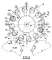
- Figure 1 is a schematic plan view of the bottle filling machine;
- Figure 2 is a vertical, cross sectional view of one of the filling valves of the device claimed;
- Figure 3 is a schematic plan view of the machine showing the different stages in the operation of the device claimed;
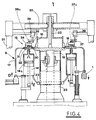
- Figure 4 is a cross section, along line IV-IV, of the filling machine illustrated in Fig.3.
- With reference to the drawings just listed, the machine for filling
bottles 1 with a liquid product has means 2 for feeding the said bottles to acarousel 3 which rotates about a vertical axis in the direction indicated by arrow A. - Feed means 2 consist of a
bottle 1 conveying line 4 along which there is anauger 5 which rotates axially in such a manner as to space the conveyedbottles 1 apart. Auger 5 is designed to operate in conjunction with adistributor 6, shaped like a star, for example, which rotates in the direction of arrow B. The bottles to be fed are held and guided byrecesses 6a indistributor 6 and byring guide 7 which partially surrounds the distributor itself. - Carousel 3 receives
bottles 1 fed bydistributor 6 one by one at the point where the equallyspaced grippers 8, mounted on the circumference of the carousel itself, are activated. Carousel 3 also mounts dispensing units, labelled 9 in the drawings, which fill the liquid product intobottles 1. - Downstream of
carousel 3 there is a full bottle outfeedsystem 10 consisting of aconveyor line 11 and anotherdistributor 12, shaped like a star, for example, which rotates in the direction of arrow C. - The outgoing bottles are received by
distributor 12 at the point where they are released bygrippers 8 and are held and guided byrecesses 12a in the distributor and by aring guide 13 which partially surrounds the distributor. - In the preferred embodiment, dispensing
units 9 consist of a plurality of cylinder and plunger assemblies mounted bycarousel 3 which lines them up withgrippers 8. Each of the said cylinder andplunger assemblies 14 is connected through avalve 15 to aliquid feed chamber 16 and to a fillingnozzle 17 alternately.Chamber 16 is mounted on aplatform 18 attached to the rotating part ofcarousel 3. -
Platform 18 is secured to the top of avertical shaft 19, rotated continuously by the drive motor of the machine. -
Chamber 16, concentric with the axis ofcarousel 3, is fed through atube 20 connected to a tank, which is not illustrated, outside the machine. Tube 20 is located abovechamber 16, diametrically with respect tocarousel 3, and is supported by aframe 21 attached to the fixed structure of the machine.Tube 20 is connected to amouthpiece 22 leading out ofchamber 16 in accordance with the axis of rotation of the carousel. - As shown in detail in Fig.2,
valve 15 consists of alower casing 23 fixed tocarousel platform 18 and anupper casing 24 which rotates on apin 25 about the vertical axis ofvalve 15 itself and in relation to fixedlower casing 23.Upper casing 24 has acap 26 held bypin 25 and pushed axially by aspring 27 which presses down oncasing 24. -
Lower casing 23 is crossed by a pair of parallel,vertical holes platform 18. Duct 30 leads out ofchamber 16, whilstduct 31 is connected to dispensingnozzle 17. -
Platform 18 is also crossed by avertical hole 32, whose bottom end is connected to cylinder andplunger assembly 14 and whose top end extends intolower casing 23 of the valve. The axes ofholes upper valve casing 24. - Upper, rotating
casing 24, on the other hand, is crossed by an approximatelysemicircular channel 33 in a horizontal plane. At each end and in the middle ofchannel 33 there are downwardopening holes hole 32 toducts valve casing 24. -
Cap 26 of rotatingcasing 24 has on its top aneccentric pin 34 which rotates axially and held by a sprungbolt 35. -
Pin 34 is designed to intercept a pair ofcams carousel 3, the said cams being carried byfixed frame 21 of the machine in diametrically opposite positions in relation to the axis of the carousel itself.Cams pin 34.Cams actuators positions pins 34. The raising ofcams - The device claimed will now be described, with reference to Fig.3 in particular, starting from the moment when
grippers 8 and related cylinder and plunger assemblies 14, rotated bycarousel 3, move to the area where the aforesaid bottles, fed bydistributor 6, are picked up. In this area,grippers 8 grip the neck ofbottle 1 to be filled, and the bottle is then lifted in the direction ofnozzle 17 of dispensingunit 9, as shown by arrow D in Fig.4. During this stage,channel 33 ofupper casing 24 ofvalve 15, is connected throughholes duct 30 and to hole 32 leading into cylinder andplunger assembly 14. The said cylinder andplunger assembly 14 is thus connected tofeed chamber 16 and liquid is sucked into the cylinder when plunger 14a is driven downwards in the direction of arrow E shown in Fig. 4. - When
nozzle 17 has been inserted intobottle 1, cylinder andplunger assembly 14 is ready to discharge its fill of liquid. For this purpose,valve 15 switches the connection of cylinder andplunger assembly 14 fromliquid suction duct 30 toduct 31 which conveys the liquid tonozzle 17. To obtain this action,eccentric pin 34 of the valve is intercepted bycam 36, thus causingupper casing 24 of the valve to rotate in relation to lower, fixedcasing 23. In this way,channel 33 ofcasing 24 is connected throughholes hole 32 and toduct 31, thus enabling the liquid to flow out through the nozzle. - Filling is completed when the flow of liquid stops and, in synchrony with the interruption of liquid flow,
bottle 1 is lowered again untilnozzle 17 is disengaged. - When the nozzle is disengaged,
cam 37 interceptseccentric pin 34, causingcasing 24 ofvalve 15 to rotate to the initial position, that is to say, withchannel 33 connected toduct 30 and cylinder andplunger assembly 14. At the same time, the next suction stage begins and liquid flows into cylinder andplunger assembly 14. - The full bottle is transferred to
distributor 12 ofoutfeed system 10. Obviously, the work cycle described above is carried out by all dispensingunits 9 mounted on the circumference ofcarousel 3. - In short, the device described constitutes a reliable, efficient means to supply a liquid product to the dispensing
units 9 rotated by the carousel. - It should be stressed in particular that the supply of liquid to dispensing
units 9 is effected by a single valve for each dispensingnozzle 17. The said valves are rotated bycarousel 3 and are fed by a chamber mounted on the same axis ascarousel 3 itself. - In this way the space occupied by the device is very limited, making for a very practical set-up, and allowing easy access to the internal parts of the carousel, while the simple structure of the device gives efficiency and reliability.
Claims (5)
- A device for dispensing liquid products to containers in automatic filling machines,these machines consisting of:
means (2) for feeding containers (1) to be filled; a carousel (3) rotating about a vertical axis and designed to receive containers (1) one by one from the feed means (2);
means (8) for holding the containers (1), said grippers being mounted on the circumference of said carousel (3);
liquid dispensing units (9), also mounted on the carousel (3), which operate synchronously with said grippers (8) for filling said containers (1), said dispensing units (9) including a plurality of cylinder and plunger assemblies (14), each of which corresponds to one of said grippers (8);
an outfeed unit (10) for moving the full containers away from said carousel (3);
the said device including:
a liquid feed chamber (16) concentrically mounted on a platform (18) of said carousel (3);
a plurality of ducts (30) leading out of said liquid feed chamber and a plurality of ducts (31) which lead to related dispensing nozzles (17),
a plurality of valves (15) mounted on the circumference of said platform (18), each related to one of the said dispensing units (9), each of said valves (15) connecting a related cylinder and plunger assembly (14), rotated by said carousel (3), alternately to a related duct (30) leading out of said liquid feed chamber (16),
so as to suck liquid from said chamber (16), and then to a related duct (31) which leads to a dispensing nozzle (17) so that the liquid is allowed to flow into said dispensing nozzle (17);
the said device being characterized in that said means for holding the containers are grippers and in that each of said valves (15) consists of a lower casing (23), fixed to said platform (18) of said carousel (3) and an upper casing (24) which rotates about the vertical axis of the valve (15) itself in relation to said lower casing (23), said upper casing (24) being crossed by a channel (33) along which there are made downward opening holes (33a,33b,33c) which serve, together with said channel (33), to connect a cylinder and plunger assembly (14) alternately to a related duct (30) leading out of said liquid feed chamber (16) and then to a related duct (31) which leads to a dispensing nozzle (17), while said lower casing (23) is crossed by a pair of parallel, vertical holes (28,29), which, at their bottom ends, are connected with said ducts (30,31), which are all made in platform (18), the said platform being also crossed by a vertical hole (32), whose bottom end is connected to a cylinder and plunger assembly (14) and whose top end extends into the lower casing (23) of the valve, the axes of said vertical holes (28,29) in the lower casing and of said vertical hole (32) in the platform being, distributed around a circle concentric with the axis of rotation of the upper valve casing (24). - A device according to claim 1, characterized in that said channel (33) has the shape of an arc, forming almost a semicircle, in a horizontal plane, while said downward opening holes (33a,33b,33c) are made at each end and in the middle of said channel (33).
- A device according to claim 1, characterized in that the top of said upper, rotary casing (24) has on it an eccentric pin (34) which rotates axially and which is designed to intercept a pair of cams (36,37), respectively first and second cam, during the rotation of carousel (3), the said cams being carried by a fixed frame (21) of the machine in diametrically opposite positions in relation to said carousel (3).
- A device according to claim 3, characterized in that said cams (36,37) are supported by actuators (38,39), respectively, driven in a vertical direction in such a manner that they can be lifted to positions (36a,37a) in which they are disengaged from said eccentric pin (34).
- A device according to claim 1, characterized in that said chamber (16) is supplied through a tube (20) connected to a tank outside the machine and located above chamber (16), diametrically with respect to carousel (3), the said tube (20) being supported by a fixed frame (21) and connected to a mouthpiece (22) leading out of chamber (16) in accordance with the axis of rotation of carousel (3).
Applications Claiming Priority (2)
| Application Number | Priority Date | Filing Date | Title |
|---|---|---|---|
| IT00373590A IT1242879B (en) | 1990-11-14 | 1990-11-14 | DEVICE FOR THE DISPENSING OF LIQUID SUBSTANCES TO ROTATING ORGANS, IN PARTICULAR IN AUTOMATIC MACHINES FOR FILLING CONTAINERS WITH SUCH LIQUID SUBSTANCES. |
| IT373590 | 1990-11-14 |
Publications (2)
| Publication Number | Publication Date |
|---|---|
| EP0486440A1 EP0486440A1 (en) | 1992-05-20 |
| EP0486440B1 true EP0486440B1 (en) | 1994-06-08 |
Family
ID=11111582
Family Applications (1)
| Application Number | Title | Priority Date | Filing Date |
|---|---|---|---|
| EP91830492A Expired - Lifetime EP0486440B1 (en) | 1990-11-14 | 1991-11-12 | Device for dispensing liquid products to rotating elements, especially in bottling machines |
Country Status (4)
| Country | Link |
|---|---|
| EP (1) | EP0486440B1 (en) |
| DE (1) | DE69102399T2 (en) |
| ES (1) | ES2055577T3 (en) |
| IT (1) | IT1242879B (en) |
Cited By (1)
| Publication number | Priority date | Publication date | Assignee | Title |
|---|---|---|---|---|
| EP3487329B1 (en) | 2016-07-20 | 2020-09-02 | Sluis Cigar Machinery B.V. | Simulated cigarette parts reorienting apparatus |
Families Citing this family (5)
| Publication number | Priority date | Publication date | Assignee | Title |
|---|---|---|---|---|
| IT1285725B1 (en) * | 1996-05-30 | 1998-06-18 | Marchesini Group Spa | MULTI-WAY HYDRAULIC VALVE, PARTICULARLY FOR AUTOMATIC MACHINES FOR FILLING CONTAINERS WITH LIQUID SUBSTANCES |
| FR2788046B1 (en) | 1999-01-06 | 2001-01-26 | Sidel Sa | FILLING MACHINE COMPRISING A REMOTE VALVE |
| JP6247071B2 (en) * | 2013-10-11 | 2017-12-13 | サッポロビール株式会社 | Support member and fluid distributor |
| CN113828369B (en) * | 2021-09-14 | 2023-02-28 | 苏州环美生物医疗科技有限公司 | Liquid suction device |
| CN114950860B (en) * | 2022-05-31 | 2023-11-07 | 中科纳通(重庆)电子材料有限公司 | A point gum machine for nickel carbon processing technology |
Family Cites Families (4)
| Publication number | Priority date | Publication date | Assignee | Title |
|---|---|---|---|---|
| GB1383346A (en) * | 1972-04-05 | 1974-02-12 | Mather & Platt Ltd | Filling devices |
| US4060109A (en) * | 1976-05-14 | 1977-11-29 | Kewpie Kabushiki Kaisha | Filling quantity regulating system in container filling apparatus |
| FR2474010A1 (en) * | 1980-01-17 | 1981-07-24 | Pont A Mousson | REFRIGERATOR FOR INSTALLATION OF PACKAGING OF CONTAINERS, PARTICULARLY BOTTLES OF CARBONATE LIQUIDS |
| IT1214901B (en) * | 1985-11-11 | 1990-01-31 | Simonazzi Spa A & L | CONTINUOUS ROTARY FILLER EQUIPPED, FOR THE MECHANICAL LIFTING OF THE EMPTY BOTTLES AND FOR THE FREE LOWERING OF THE FILLED BOTTLES, ONLY WITH WITH PRENSILE TAPS EQUIPPED WITH A SYNCHRONIZED LOCKING LOCK WITH THE DIRI PROCESS |
-
1990
- 1990-11-14 IT IT00373590A patent/IT1242879B/en active IP Right Grant
-
1991
- 1991-11-12 EP EP91830492A patent/EP0486440B1/en not_active Expired - Lifetime
- 1991-11-12 DE DE69102399T patent/DE69102399T2/en not_active Expired - Fee Related
- 1991-11-12 ES ES91830492T patent/ES2055577T3/en not_active Expired - Lifetime
Cited By (1)
| Publication number | Priority date | Publication date | Assignee | Title |
|---|---|---|---|---|
| EP3487329B1 (en) | 2016-07-20 | 2020-09-02 | Sluis Cigar Machinery B.V. | Simulated cigarette parts reorienting apparatus |
Also Published As
| Publication number | Publication date |
|---|---|
| IT9003735A0 (en) | 1990-11-14 |
| IT9003735A1 (en) | 1992-05-14 |
| DE69102399D1 (en) | 1994-07-14 |
| ES2055577T3 (en) | 1994-08-16 |
| EP0486440A1 (en) | 1992-05-20 |
| DE69102399T2 (en) | 1994-11-24 |
| IT1242879B (en) | 1994-05-18 |
Similar Documents
| Publication | Publication Date | Title |
|---|---|---|
| US7114535B2 (en) | Circular motion filling machine and method | |
| EP0486439B1 (en) | Device for synchronously driving the dispensing and the container handling means in bottling machines | |
| US7779874B2 (en) | Method of filling kegs with a liquid beverage in a keg filling plant | |
| US5551491A (en) | Automatic carousel machine for the metered feeding and packaging of fluid products | |
| US6832640B2 (en) | Device for gripping and handling bottles in a labeling machine and method of bottle filling/pressurising | |
| US7059104B2 (en) | System for filling and closing fluid containing cartridges | |
| GB1383346A (en) | Filling devices | |
| EP1549547B1 (en) | A method and a machine for dispensing fluid substances into containers | |
| EP1857087A1 (en) | Machine for filling containers with at least one granular product | |
| EP0486440B1 (en) | Device for dispensing liquid products to rotating elements, especially in bottling machines | |
| US20070289665A1 (en) | Container transportation line bottling plants | |
| US5158168A (en) | Container transfer device | |
| GB898385A (en) | Improvements in or relating to apparatus for filling containers | |
| EP0486438B1 (en) | Method and machine for filling containers with liquid products | |
| USRE31393E (en) | Star-wheel indexing system for automatic filling machines | |
| US20180354764A1 (en) | Apparatus and method for filling and sealing containers | |
| EP3747561A1 (en) | Washing machine for containers, in particular for products of the pharmceutical industry | |
| US3259152A (en) | Apparatus for filling and shaking a can | |
| JP3897394B2 (en) | Irregular container filling device | |
| US3759012A (en) | Device for fitting caps to containers | |
| EP0798263A1 (en) | Container capping and filling apparatus | |
| CN210028041U (en) | Automatic bottle capping mechanism | |
| US3550648A (en) | Method and apparatus for filling multiple cavity containers with measured charges of liquid | |
| RU2098346C1 (en) | Automatic packaging machine | |
| JPH04286518A (en) | Cap supply device |
Legal Events
| Date | Code | Title | Description |
|---|---|---|---|
| PUAI | Public reference made under article 153(3) epc to a published international application that has entered the european phase |
Free format text: ORIGINAL CODE: 0009012 |
|
| AK | Designated contracting states |
Kind code of ref document: A1 Designated state(s): CH DE ES FR GB LI |
|
| 17P | Request for examination filed |
Effective date: 19921030 |
|
| 17Q | First examination report despatched |
Effective date: 19930615 |
|
| GRAA | (expected) grant |
Free format text: ORIGINAL CODE: 0009210 |
|
| AK | Designated contracting states |
Kind code of ref document: B1 Designated state(s): CH DE ES FR GB LI |
|
| PG25 | Lapsed in a contracting state [announced via postgrant information from national office to epo] |
Ref country code: CH Effective date: 19940608 Ref country code: LI Effective date: 19940608 |
|
| REF | Corresponds to: |
Ref document number: 69102399 Country of ref document: DE Date of ref document: 19940714 |
|
| ET | Fr: translation filed | ||
| REG | Reference to a national code |
Ref country code: ES Ref legal event code: FG2A Ref document number: 2055577 Country of ref document: ES Kind code of ref document: T3 |
|
| REG | Reference to a national code |
Ref country code: CH Ref legal event code: PL |
|
| PLBE | No opposition filed within time limit |
Free format text: ORIGINAL CODE: 0009261 |
|
| STAA | Information on the status of an ep patent application or granted ep patent |
Free format text: STATUS: NO OPPOSITION FILED WITHIN TIME LIMIT |
|
| 26N | No opposition filed | ||
| REG | Reference to a national code |
Ref country code: GB Ref legal event code: IF02 |
|
| PGFP | Annual fee paid to national office [announced via postgrant information from national office to epo] |
Ref country code: DE Payment date: 20081128 Year of fee payment: 18 |
|
| PGFP | Annual fee paid to national office [announced via postgrant information from national office to epo] |
Ref country code: FR Payment date: 20081118 Year of fee payment: 18 Ref country code: ES Payment date: 20081127 Year of fee payment: 18 |
|
| PGFP | Annual fee paid to national office [announced via postgrant information from national office to epo] |
Ref country code: GB Payment date: 20081127 Year of fee payment: 18 |
|
| GBPC | Gb: european patent ceased through non-payment of renewal fee |
Effective date: 20091112 |
|
| REG | Reference to a national code |
Ref country code: FR Ref legal event code: ST Effective date: 20100730 |
|
| PG25 | Lapsed in a contracting state [announced via postgrant information from national office to epo] |
Ref country code: FR Free format text: LAPSE BECAUSE OF NON-PAYMENT OF DUE FEES Effective date: 20091130 |
|
| PG25 | Lapsed in a contracting state [announced via postgrant information from national office to epo] |
Ref country code: DE Free format text: LAPSE BECAUSE OF NON-PAYMENT OF DUE FEES Effective date: 20100601 |
|
| PG25 | Lapsed in a contracting state [announced via postgrant information from national office to epo] |
Ref country code: GB Free format text: LAPSE BECAUSE OF NON-PAYMENT OF DUE FEES Effective date: 20091112 |
|
| REG | Reference to a national code |
Ref country code: ES Ref legal event code: FD2A Effective date: 20110307 |
|
| PG25 | Lapsed in a contracting state [announced via postgrant information from national office to epo] |
Ref country code: ES Free format text: LAPSE BECAUSE OF NON-PAYMENT OF DUE FEES Effective date: 20110304 |
|
| PG25 | Lapsed in a contracting state [announced via postgrant information from national office to epo] |
Ref country code: ES Free format text: LAPSE BECAUSE OF NON-PAYMENT OF DUE FEES Effective date: 20091113 |