EP3487329B1 - Simulated cigarette parts reorienting apparatus - Google Patents
Simulated cigarette parts reorienting apparatus Download PDFInfo
- Publication number
- EP3487329B1 EP3487329B1 EP17754813.8A EP17754813A EP3487329B1 EP 3487329 B1 EP3487329 B1 EP 3487329B1 EP 17754813 A EP17754813 A EP 17754813A EP 3487329 B1 EP3487329 B1 EP 3487329B1
- Authority
- EP
- European Patent Office
- Prior art keywords
- reorienting
- simulated cigarette
- section
- unit
- cam
- Prior art date
- Legal status (The legal status is an assumption and is not a legal conclusion. Google has not performed a legal analysis and makes no representation as to the accuracy of the status listed.)
- Active
Links
- 235000019504 cigarettes Nutrition 0.000 title claims description 95
- 230000005540 biological transmission Effects 0.000 claims description 34
- 230000013011 mating Effects 0.000 claims description 34
- 239000000969 carrier Substances 0.000 claims description 27
- 230000007246 mechanism Effects 0.000 claims description 22
- 238000000034 method Methods 0.000 claims description 13
- 238000011144 upstream manufacturing Methods 0.000 claims description 7
- 238000003825 pressing Methods 0.000 description 5
- 238000006073 displacement reaction Methods 0.000 description 4
- 238000004519 manufacturing process Methods 0.000 description 2
- 230000001419 dependent effect Effects 0.000 description 1
- 239000003571 electronic cigarette Substances 0.000 description 1
Images


Classifications
-
- A—HUMAN NECESSITIES
- A24—TOBACCO; CIGARS; CIGARETTES; SIMULATED SMOKING DEVICES; SMOKERS' REQUISITES
- A24F—SMOKERS' REQUISITES; MATCH BOXES; SIMULATED SMOKING DEVICES
- A24F40/00—Electrically operated smoking devices; Component parts thereof; Manufacture thereof; Maintenance or testing thereof; Charging means specially adapted therefor
- A24F40/70—Manufacture
-
- B—PERFORMING OPERATIONS; TRANSPORTING
- B65—CONVEYING; PACKING; STORING; HANDLING THIN OR FILAMENTARY MATERIAL
- B65G—TRANSPORT OR STORAGE DEVICES, e.g. CONVEYORS FOR LOADING OR TIPPING, SHOP CONVEYOR SYSTEMS OR PNEUMATIC TUBE CONVEYORS
- B65G47/00—Article or material-handling devices associated with conveyors; Methods employing such devices
- B65G47/22—Devices influencing the relative position or the attitude of articles during transit by conveyors
- B65G47/24—Devices influencing the relative position or the attitude of articles during transit by conveyors orientating the articles
-
- B—PERFORMING OPERATIONS; TRANSPORTING
- B65—CONVEYING; PACKING; STORING; HANDLING THIN OR FILAMENTARY MATERIAL
- B65G—TRANSPORT OR STORAGE DEVICES, e.g. CONVEYORS FOR LOADING OR TIPPING, SHOP CONVEYOR SYSTEMS OR PNEUMATIC TUBE CONVEYORS
- B65G2201/00—Indexing codes relating to handling devices, e.g. conveyors, characterised by the type of product or load being conveyed or handled
- B65G2201/02—Articles
- B65G2201/0226—Cigarettes
-
- B—PERFORMING OPERATIONS; TRANSPORTING
- B65—CONVEYING; PACKING; STORING; HANDLING THIN OR FILAMENTARY MATERIAL
- B65G—TRANSPORT OR STORAGE DEVICES, e.g. CONVEYORS FOR LOADING OR TIPPING, SHOP CONVEYOR SYSTEMS OR PNEUMATIC TUBE CONVEYORS
- B65G29/00—Rotary conveyors, e.g. rotating discs, arms, star-wheels or cones
-
- B—PERFORMING OPERATIONS; TRANSPORTING
- B65—CONVEYING; PACKING; STORING; HANDLING THIN OR FILAMENTARY MATERIAL
- B65G—TRANSPORT OR STORAGE DEVICES, e.g. CONVEYORS FOR LOADING OR TIPPING, SHOP CONVEYOR SYSTEMS OR PNEUMATIC TUBE CONVEYORS
- B65G47/00—Article or material-handling devices associated with conveyors; Methods employing such devices
- B65G47/34—Devices for discharging articles or materials from conveyor
- B65G47/46—Devices for discharging articles or materials from conveyor and distributing, e.g. automatically, to desired points
- B65G47/51—Devices for discharging articles or materials from conveyor and distributing, e.g. automatically, to desired points according to unprogrammed signals, e.g. influenced by supply situation at destination
- B65G47/5104—Devices for discharging articles or materials from conveyor and distributing, e.g. automatically, to desired points according to unprogrammed signals, e.g. influenced by supply situation at destination for articles
- B65G47/5109—Devices for discharging articles or materials from conveyor and distributing, e.g. automatically, to desired points according to unprogrammed signals, e.g. influenced by supply situation at destination for articles first In - First Out systems: FIFO
- B65G47/5136—Devices for discharging articles or materials from conveyor and distributing, e.g. automatically, to desired points according to unprogrammed signals, e.g. influenced by supply situation at destination for articles first In - First Out systems: FIFO using rotary conveyors
Definitions
- the present invention relates to a reorienting device for reorienting simulated cigarette parts (also: parts) relative to a product carrier in which they are supported to a predetermined orientation.
- the parts are received from a first track, reoriented and delivered to a second track in the predetermined orientation relative to the product carrier.
- the present invention also relates to a method of reorienting simulated cigarette parts.
- a manufacturing process of parts of a simulated cigarette various processing operations generally need to be carried out on the parts.
- the parts are generally carried by a product carrier.
- the parts may be relatively small and may be quite fragile.
- the processing operations may need to be carried out in a specific way.
- the possibilities of controlling the position and orientation of these parts relative to the product carrier during the various processing steps in an assembly line are limited.
- the orientation of the parts may be random during the conveying of the parts through an assembly line, and this may seriously hinder a processing operation.
- the parts may simply have a wrong orientation so that it becomes impossible to carry out the processing operation.
- WO 2012/077147 A1 discloses a series of article-handling machines comprising a common first rotating element rotatable about an axis, wherein each article-handling machine comprises a carousel for conveying a plurality of articles along a path and a first connecting element which is angularly integral with carousel and is releasably connected to first rotating element.
- DE 37 28 291 A1 discloses a process and apparatus for arranging and holding a plurality of pack units in a common receiving container. Individual bottles are to be placed and held in the compartments of the bottle case in such a rotary position that the label remains visible on the outside.
- the first orientation may be a random orientation.
- the invention relates to a reorienting device for reorienting simulated cigarette parts which are carried by a product carrier about a vertical product axis from a first angular orientation to a second, predetermined orientation relative to said product carrier, the reorienting device comprising:
- the present invention was found to provide a reliable and effective way of reorienting the products in their product carriers.
- the first section of the reorienting unit is movable between an upper position and a lower position and the second section is fixed in a direction of the unit axis.
- the resilient member of the reorienting unit vertically displaces the first section and biases the first section in a downward direction.
- the first cam track has a varying radius R relative to the main axis of rotation causing a radial movement of the cam when the cam travels along the first cam track during the rotary movement of the rotary carrousel.
- each transmission mechanism comprises a transmission gear which is attached to the cam.
- Each reorienting unit comprises an actuating gear.
- the actuating gear extends around the unit axis and engages the transmission gear of the transmission mechanism.
- a radial movement of the cam results in a movement of the transmission gear.
- the movement of the transmission gear results in turn in a movement of the actuating gear.
- the second cam track comprises:
- the second cam track further comprises a substantially horizontal section located downstream from the upward slope section and upstream from the downward slope section, wherein the reorienting units arrive at the substantially horizontal section after having been moved upward by the upward slope section, wherein the first section of each reorienting unit is in the upper position when travelling along the substantially horizontal section.
- the first cam track extends in a plane substantially perpendicular to the main vertical rotation axis.
- the first and second cam tracks are stationary.
- the first cam track is endless.
- the second cam track extends along a part of the trajectory of the reorienting units.
- the rotary carrousel may make a continuous movement, in particular a rotary movement.
- each engagement member is provided at the lower end of the respective reorienting unit and engages an upper side of the simulated cigarette part.
- the first section comprises the engagement member which comprises a first mating part configured to engage a second mating part provided at the upper side of the simulated cigarette part.
- the first mating part comprises a male or female centering part configured to concentrically align the engagement member with the simulated cigarette part, wherein a center of the first mating part is located on the vertical unit axis, and wherein the centering part protrudes beyond one or more side protrusions, which one or more side protrusions extend radially outward from the vertical unit axis.
- the male or female centering part is conical.
- the first section has the engagement member which in turn has a protrusion which engages a mating shape provided in the upper side of the simulated cigarette part.
- the first angular orientation of the simulated cigarette parts is arbitrary and the engagement member:
- the second angular orientation is a predetermined orientation.
- the product carrier movers maintain the angular position of the product carriers when the simulated cigarette parts which are held by the product carriers are reoriented.
- the present invention further relates to a method for reorienting simulated cigarette parts, the method comprising:
- the vertical displacement of the first section of the reorienting units comprises the steps:
- step e) entails pressing the protrusion into a recess of the simulated cigarette part due to the force of the resilient member, thereby reaching the lowest position of the first section of the reorienting unit.
- the first angular orientation of the simulated cigarette parts is arbitrary and the engagement member engages the simulated cigarette part carried by a product carrier, the method comprising:
- the vertical displacement of the first section of the reorienting units takes place during the rotary movement of the reorienting units about the main vertical rotation axis.
- a simulated cigarette part reorienting device 10 for reorienting simulated cigarette parts 12 which are carried by a product carrier 14.
- the simulated cigarette parts 12 are reoriented about a vertical product axis 16 from a first angular orientation 18 to a second, predetermined orientation 20 relative to said product carrier.
- the product carriers carrying the parts are transported along a track starting at entrance 90 and ending at exit 92.
- the product carriers are guided by the conveyors 94, 96, 97 and 98 in the direction indicated by the arrows 91.
- the reorienting device is located downstream from conveyor 97 and upstream from conveyor 98.
- the tracks are supported by the track support frame 100.
- the reorienting device has a first cam track 22 (shown in figure 2 ) extending around a main vertical rotation axis 24 and having a varying radius R.
- the cam track is supported by a cam track support 34. Due to the varying radius R, cams 52 following the cam track move radially during the rotary movement of a rotary carrousel 30.
- the rotary carrousel rotates about the main vertical rotation axis and comprises a rotary support frame 32 configured to rotate about the main vertical rotation axis.
- the first cam track 22 has a varying radius R relative to the main vertical rotation axis 24.
- the varying radius R causes a radial movement of the cam 52 when the cam travels along the first cam track during the rotary movement of the rotary carrousel.
- the first cam track is also endless and extends in a plane substantially perpendicular to the main vertical rotation axis 24.
- a second cam track 70 is provided around a trajectory of the circular track 62.
- the second cam track 70 induces a vertical displacement of the first section of the reorienting units 40.
- Both the first cam track 22 and the second cam track are stationary.
- Figure 3 shows the rotary carrousel 30.
- a plurality of reorienting units 40 are connected to the rotary support frame 32. Although only one reorienting unit is shown, the skilled person will understand that the invention comprises a plurality of reorienting units. They are arranged in a circular configuration when viewed in top view. Each reorienting unit 40 projects downward from the rotary support frame through an opening in the rotary support frame.
- Each reorienting unit 40 is constructed with a second section 45 which is fixed in vertical direction relative to the rotary support frame 32.
- the rotary carrousel 30 further comprises a plurality of transmission mechanisms 50 connected to the rotary support frame 32.
- Figure 3 only shows one transmission mechanism, but the skilled person will understand that the invention discloses a plurality of transmission mechanisms.
- Each transmission mechanism is associated with a reorienting unit 40.
- the transmission mechanism comprises a cam 52 which moves along the first cam track 22 during the rotation of the rotary support frame.
- the transmission mechanism converts a movement of the cam into a rotation of the first section 44 of the reorienting unit about the vertical unit axis relative to the rotary support frame.
- the transmission mechanism 50 as shown in figure 3 and 5 comprises a transmission gear 54 which is attached to the cam 52.
- Each reorienting unit comprises an actuating gear 41 which extends around the unit axis and engages the transmission gear of the transmission mechanism. A radial movement of the cam results in a movement of the transmission gear. This will result in turn in a movement of the actuating gear.
- each reorienting unit 40 consists of an engagement member 42 which engages the simulated cigarette part.
- the engagement member may comprise a protrusion 80 and/or a recess. After engaging the simulated cigarette part, the engagement member reorients it about the vertical product axis 16 relative to the product carrier.
- the reorienting unit itself comprises a first section 44 that rotates about a vertical unit axis 46 relative to the rotary support frame. The first section can move in a vertical direction between an upper position 48 and a lower position 49. The upper position is a retracted position and the lower position is an engagement position.
- Each engagement member 42 is provided at the lower end of the respective reorienting unit 40.
- the first section of the reorienting unit comprises the said engagement member.
- An upper side of the simulated cigarette parts comprises a mating shape. This may be a protrusion or a recess, or a combination. In case of a recess, the engagement member comprises a mating protrusion 80. The protrusion then engages and fit in the mating shape of the simulated cigarette part during operation.
- Figure 4 shows a schematic view of the vertical movement of the first section, wherein figures 4A and 4H depict the upper position and figures 4D-4G depict the lower, engagement position.
- figures 4A and 4H depict the upper position
- figures 4D-4G depict the lower, engagement position.
- the first section is also engaged, but not in its lower position.
- the reorienting units are configured in a circular manner instead of the linear representation of figure 4 .
- Figure 4A shows the reorienting unit 40 in the upper position 48.
- Figure 4B shows the engagement member 42, the protrusion 80 in contact with the upper side of the simulated cigarette part. From figure 4B to figure 4C , the protrusion slides over the upper side of the part carried by the product carrier in a rotary manner. The protrusion keeps on rotating and sliding over the upper side until the protrusion is positioned exactly above the mating shape 82, in this case a recess.
- the resilient member 47 ( figure 5 ) forces the protrusion into the mating shape. This is shown in figure 4D and the first section 44 of the reorienting unit is in the lower position 49.
- Figures 11A-11D show more generally a first mating part 81 provided on the engagement member 42.
- the first mating part 81 is a protruding part
- the first mating part 81 in figure 11B is a recess. Both configurations are possible, as long as the simulated cigarette part has a second mating part 83 at an upper side thereof which mates with the first mating part. If the first mating part 81 is protruding, then the second mating part 83 has at least a recess to accommodate the protruding part of the fist mating part 81, or vice versa.
- Figure 11A further shows the first mating shape 81 comprising a male or female centering part 84 configured to concentrically align the engagement member with the simulated cigarette part. This speeds up the engagement of the engagement member with the simulated cigarette part. It also increases the reliability.
- a center 85 of the first mating shape is located on the vertical unit axis 46.
- the centering part 84 protrudes beyond one or more side protrusions 86, in the shown embodiment beyond two side protrusions 86.
- the side protrusions 86 extend radially outward from the vertical unit axis 46.
- the male or female centering part is conical.
- Figures 4D to 4G show the reorienting of the simulated cigarette part.
- Figure 4G also shows the second, predetermined orientation 20 of the part carried by the product carrier. With the part in the second, predetermined orientation, the reorienting unit arrives upstream from the upward slope section 72 of the second cam track 70, see figure 1 . Due to the upward slope section the engagement member moves upwards and disengages the simulated cigarette part. This is shown in figure 4H . At this stage the part is in the second, predetermined orientation and the first section of the reorienting unit is in the upper position.
- the reorienting unit 40 comprises a first section 44 which moves between an upper position 48 and a lower position 49.
- a resilient member 47 in the form of a helical spring is provided in the reorienting unit and vertically displaces the first section and biases the first section in a downward direction.
- the resilient member acts on a second section 45 of the reorienting unit.
- the second section is fixed in the direction of a vertical unit axis 46.
- the reorienting device further comprises a moving device 60 for moving the product carriers.
- the moving device consists of a circular track 62 that is located underneath the reorienting units 40 and guides the product carriers 14 holding the simulated cigarette parts.
- the moving device comprises a plurality of product carrier movers 64 which move the product carriers along the said circular track underneath the reorienting units.
- the product carrier movers 64 are provided in a body which resembles a gear.
- the product carriers are supported by the circular track 62 and are only pushed forward in a horizontal direction by the moving device.
- the product carrier movers 64 maintain the angular position of the product carriers during the reorientation of the simulated cigarette part.
- the simulated cigarette parts are held by the product carriers.
- the second cam track 70 as shown in figure 8 consists of an upward slope 72, a substantially horizontal section 76 and a downward slope section 74.
- the reorienting units arrive at an upstream end of the upward slope section in the lower position 49 and in an engaged state with a simulated cigarette part. Subsequently, the reorienting units engage the upward slope section and are displaced upwards by the upward slope section. This causes a disengagement of the reorienting units from the simulated cigarette parts.
- the reorienting units are then guided over the substantially horizontal section located downstream from the upward slope section and upstream from the downward slope section.
- the first section of the reorienting units are in the upper position.
- the first section of the reorienting units is vertically displaced in a downward direction as it travels along the downward slope section. This makes it possible to engage the first section of each reorienting unit with a next simulated cigarette part.
- the first cam track 22 extends in a plane which is substantially perpendicular to the main vertical rotation axis 24.
- the first cam track may be also stationary and/or endless.
- the second cam track is also stationary. However, the second cam track extends along a part of a trajectory of the reorienting units.
- the rotary carrousel is intended to make a continuous movement in particular a rotary movement. This has the advantage of a high production rate.
- step e) comprises pressing the protrusion into a recess of the simulated cigarette part.
- the pressing is achieved due to the force of the resilient member. Thereby the lowest position of the first section of the reorienting unit is reached.
- the engagement member has a recess and the simulated cigarette part has a protrusion, a skilled person will understand the recess is pressed over the protrusion.
- the first angular orientation of the simulated cigarette parts is arbitrary.
- the engagement member engages the simulated cigarette part carried by a product carrier. After engaging, the simulated cigarette part is rotated relative to the product carrier. So the following steps are carried out:
- the first section of the reorienting units is displaced vertically.
Description
- The present invention relates to a reorienting device for reorienting simulated cigarette parts (also: parts) relative to a product carrier in which they are supported to a predetermined orientation. The parts are received from a first track, reoriented and delivered to a second track in the predetermined orientation relative to the product carrier. The present invention also relates to a method of reorienting simulated cigarette parts.
- In a manufacturing process of parts of a simulated cigarette (or e-cigarette) various processing operations generally need to be carried out on the parts. The parts are generally carried by a product carrier. The parts may be relatively small and may be quite fragile. The processing operations may need to be carried out in a specific way.
- In the present invention it was recognized that the possibilities of controlling the position and orientation of these parts relative to the product carrier during the various processing steps in an assembly line are limited. In particular, the orientation of the parts may be random during the conveying of the parts through an assembly line, and this may seriously hinder a processing operation. For instance, the parts may simply have a wrong orientation so that it becomes impossible to carry out the processing operation.
-
WO 2012/077147 A1 discloses a series of article-handling machines comprising a common first rotating element rotatable about an axis, wherein each article-handling machine comprises a carousel for conveying a plurality of articles along a path and a first connecting element which is angularly integral with carousel and is releasably connected to first rotating element. -
DE 37 28 291 A1 discloses a process and apparatus for arranging and holding a plurality of pack units in a common receiving container. Individual bottles are to be placed and held in the compartments of the bottle case in such a rotary position that the label remains visible on the outside. - It is an object of the invention to provide a reorienting device which reorients simulated cigarette parts which are carried by a product carrier in an assembly line from a first orientation to a second, predetermined orientation. The first orientation may be a random orientation.
- It is yet another objective to provide a device that continuously performs the reorientation of the simulated cigarette parts, and does so in a reliable manner.
- The same objects apply to the methods according to the invention.
- In order to achieve at least one of the mentioned objects, the invention relates to a reorienting device for reorienting simulated cigarette parts which are carried by a product carrier about a vertical product axis from a first angular orientation to a second, predetermined orientation relative to said product carrier, the reorienting device comprising:
- a main vertical rotation axis;
- a first cam track extending at least partially around the main vertical rotation axis;
- a rotary carrousel configured to rotate about the main vertical rotation axis, the rotary carrousel comprising;
- ∘ a rotary support frame;
- ∘ a plurality of reorienting units connected to the rotary support frame and arranged in a circular configuration when viewed in top view, each reorienting unit comprising an engagement member, wherein each engagement member is configured to engage the simulated cigarette part and to reorient it about the vertical product axis, wherein each reorienting unit comprises a first section which is rotatable relative to the rotary support frame about a vertical unit axis and is movable in a vertical direction between an upper position and a lower position, the upper position being a retracted position and the lower position being an engagement position;
- ∘ a plurality of transmission mechanisms connected to the rotary support frame, each transmission mechanism being associated with a respective reorienting unit, each transmission mechanism comprising a cam which moves along the first cam track during the rotation of the rotary support frame, wherein the transmission mechanisms convert a movement of the cam into a rotation of the first section of the reorienting unit about the vertical unit axis relative to the rotary support frame;
- a moving device for moving the product carriers, the moving device comprising:
- ∘ a circular track located underneath the reorienting units and configured to guide the product carriers holding the simulated cigarette parts;
- ∘ a plurality of product carrier movers for moving the product carriers along the circular track underneath the reorienting units,
- a second cam track configured to vertically displace the first section of the reorienting units.
- The present invention was found to provide a reliable and effective way of reorienting the products in their product carriers.
- In an embodiment, the first section of the reorienting unit is movable between an upper position and a lower position and the second section is fixed in a direction of the unit axis.
- In an embodiment, the resilient member of the reorienting unit vertically displaces the first section and biases the first section in a downward direction.
- In an embodiment, the first cam track has a varying radius R relative to the main axis of rotation causing a radial movement of the cam when the cam travels along the first cam track during the rotary movement of the rotary carrousel.
- In an embodiment, each transmission mechanism comprises a transmission gear which is attached to the cam. Each reorienting unit comprises an actuating gear. The actuating gear extends around the unit axis and engages the transmission gear of the transmission mechanism. A radial movement of the cam results in a movement of the transmission gear. The movement of the transmission gear results in turn in a movement of the actuating gear.
- In an embodiment, the second cam track comprises:
- an upward slope section wherein each reorienting unit arrives at an upstream end of the upward slope section in a lower position and in an engaged state with a simulated cigarette part, wherein the reorienting units engage the upward slope section and are moved upwards by the upward slope section, thereby causing a disengagement of the reorienting units from the simulated cigarette parts;
- a downward slope section located downstream from the upward slope section. The downward slope section displaces the first section of each reorienting unit in a downward direction. This makes it possible to engage the first section of each reorienting unit with a next simulated cigarette part.
- In an embodiment, the second cam track further comprises a substantially horizontal section located downstream from the upward slope section and upstream from the downward slope section, wherein the reorienting units arrive at the substantially horizontal section after having been moved upward by the upward slope section, wherein the first section of each reorienting unit is in the upper position when travelling along the substantially horizontal section.
- In an embodiment, the first cam track extends in a plane substantially perpendicular to the main vertical rotation axis.
- In an embodiment, the first and second cam tracks are stationary.
- In an embodiment, the first cam track is endless.
- In an embodiment, the second cam track extends along a part of the trajectory of the reorienting units.
- The rotary carrousel may make a continuous movement, in particular a rotary movement.
- In an embodiment, each engagement member is provided at the lower end of the respective reorienting unit and engages an upper side of the simulated cigarette part.
- In an embodiment, the first section comprises the engagement member which comprises a first mating part configured to engage a second mating part provided at the upper side of the simulated cigarette part.
- In an embodiment, the first mating part comprises a male or female centering part configured to concentrically align the engagement member with the simulated cigarette part, wherein a center of the first mating part is located on the vertical unit axis, and wherein the centering part protrudes beyond one or more side protrusions, which one or more side protrusions extend radially outward from the vertical unit axis.
- In an embodiment, the male or female centering part is conical.
- In an embodiment, the first section has the engagement member which in turn has a protrusion which engages a mating shape provided in the upper side of the simulated cigarette part.
- In an embodiment, the first angular orientation of the simulated cigarette parts is arbitrary and the engagement member:
- engages the simulated cigarette part and
- slides over the upper surface of the simulated cigarette part in a rotary manner until it fits into the mating shape of the simulated cigarette part, and
- subsequently presses into the mating shape by the force of the resilient member, and
- subsequently rotates the simulated cigarette part relative to the product carrier to the second, predetermined orientation.
- In an embodiment, the second angular orientation is a predetermined orientation.
- In an embodiment, the product carrier movers maintain the angular position of the product carriers when the simulated cigarette parts which are held by the product carriers are reoriented.
- The present invention further relates to a method for reorienting simulated cigarette parts, the method comprising:
- feeding product carriers to the track of the reorienting device, and moving the product carriers along said track, wherein each product carrier carries a simulated cigarette part;
- engaging the simulated cigarette part with the engagement member of the first section of each reorienting unit by a downward movement of the first section of the reorienting unit, and;
- rotating the simulated cigarette part relative to the product carrier by a rotary movement of the reorienting unit.
- In an embodiment of the method:
- each cam is moved along the first cam track during the rotary movement of the carrousel, wherein the first cam track has a varying radius R causing a radial movement of the cam when the cam travels along the first cam track;
- each transmission gear attached to its respective cam rotates about its axis when the cam moves radially and engages the actuating gear of the reorienting unit and rotates the reorienting unit;
- In an embodiment of the method, the vertical displacement of the first section of the reorienting units comprises the steps:
- a) moving the reorienting unit by the rotary support frame, wherein the first section of the reorienting unit is in the lower position and is engaged with a simulated cigarette part;
- b) moving the reorienting unit along the upward slope section of the second cam track, wherein the first section of each reorienting unit is moved upward and disengages from the simulated cigarette part;
- c) moving the reorienting unit along the substantially horizontal section of the second cam track, wherein the first section of each reorienting unit is in the upper position and not engaged with any simulated cigarette part;
- d) moving the reorienting unit along the downward slope section, wherein the first section of each reorienting unit is vertically displaced in a downward direction as it moves along the downward slope section and engages a new simulated cigarette part;
- e) moving the reorienting unit further along the track and rotating the reorienting unit, thereby reorienting the simulated cigarette part relative to the product carrier.
- In an embodiment of the method step e) entails pressing the protrusion into a recess of the simulated cigarette part due to the force of the resilient member, thereby reaching the lowest position of the first section of the reorienting unit.
- In an embodiment of the method the first angular orientation of the simulated cigarette parts is arbitrary and the engagement member engages the simulated cigarette part carried by a product carrier, the method comprising:
- sliding the engagement member over the upper surface of the simulated cigarette part in a rotary manner until the engagement member fits into the mating shape of the simulated cigarette part, and
- pressing the engagement member into the mating shape by the force of the resilient member, and
- subsequently rotating the simulated cigarette part relative to the product carrier.
- In an embodiment of the method the vertical displacement of the first section of the reorienting units takes place during the rotary movement of the reorienting units about the main vertical rotation axis.
- These and other aspects of the invention will be more readily appreciated as the same becomes better understood by reference to the following detailed description and considered in connection with the accompanying drawings in which like reference symbols designate like parts.
-
-
Figure 1 shows a general isometric view of an embodiment of the invention. -
Figure 2 shows an isometric view of an embodiment of the invention with a horizontal cross-section through the first cam track. -
Figure 3 shows an isometric view of the rotary support frame with a transmission mechanism and a reorienting unit. -
Figure 4 shows a schematic view of the simulated cigarette parts in the product carriers being engaged, reoriented and disengaged with the engagement member of the reorienting unit. -
Figure 5 shows an isometric view and a cross-sectional view of a transmission mechanism and a reorienting unit. -
Figure 6 shows a schematic view of the simulated cigarette parts in the product carriers being reoriented from a first, arbitrary orientation to a second, predetermined orientation. -
Figure 7 shows an isometric view of an embodiment of the invention, in particular the second cam track. -
Figure 8 shows an isometric view of the second cam track. -
Figure 9 shows an isometric view of the moving device with a product carrier holding a simulated cigarette part, with a reorienting device being engaged with the simulated cigarette part. -
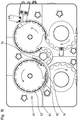
Figure 10 shows a top view of an embodiment of the invention. -
Figures 11A and 11B show a schematic view of embodiments of the engagement member. -
Figures 11C and 11D show a schematic view of embodiments of mating parts. - Turning to
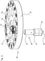
figures 1 and6 , a simulated cigarettepart reorienting device 10 is shown for reorientingsimulated cigarette parts 12 which are carried by aproduct carrier 14. Thesimulated cigarette parts 12 are reoriented about avertical product axis 16 from a firstangular orientation 18 to a second, predeterminedorientation 20 relative to said product carrier. - The product carriers carrying the parts are transported along a track starting at
entrance 90 and ending atexit 92. The product carriers are guided by theconveyors arrows 91. The reorienting device is located downstream fromconveyor 97 and upstream fromconveyor 98. The tracks are supported by thetrack support frame 100. - The reorienting device has a first cam track 22 (shown in
figure 2 ) extending around a mainvertical rotation axis 24 and having a varying radius R. The cam track is supported by acam track support 34. Due to the varying radius R,cams 52 following the cam track move radially during the rotary movement of arotary carrousel 30. The rotary carrousel rotates about the main vertical rotation axis and comprises arotary support frame 32 configured to rotate about the main vertical rotation axis. - The
first cam track 22 has a varying radius R relative to the mainvertical rotation axis 24. The varying radius R causes a radial movement of thecam 52 when the cam travels along the first cam track during the rotary movement of the rotary carrousel. The first cam track is also endless and extends in a plane substantially perpendicular to the mainvertical rotation axis 24. - Turning to
figures 1 ,2 and8 , asecond cam track 70 is provided around a trajectory of thecircular track 62. Thesecond cam track 70 induces a vertical displacement of the first section of the reorientingunits 40. Both thefirst cam track 22 and the second cam track are stationary. -
Figure 3 shows therotary carrousel 30. A plurality of reorientingunits 40 are connected to therotary support frame 32. Although only one reorienting unit is shown, the skilled person will understand that the invention comprises a plurality of reorienting units. They are arranged in a circular configuration when viewed in top view. Each reorientingunit 40 projects downward from the rotary support frame through an opening in the rotary support frame. - Each reorienting
unit 40 is constructed with asecond section 45 which is fixed in vertical direction relative to therotary support frame 32. - The
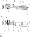
rotary carrousel 30 further comprises a plurality oftransmission mechanisms 50 connected to therotary support frame 32.Figure 3 only shows one transmission mechanism, but the skilled person will understand that the invention discloses a plurality of transmission mechanisms. Each transmission mechanism is associated with a reorientingunit 40. The transmission mechanism comprises acam 52 which moves along thefirst cam track 22 during the rotation of the rotary support frame. The transmission mechanism converts a movement of the cam into a rotation of thefirst section 44 of the reorienting unit about the vertical unit axis relative to the rotary support frame. - The
transmission mechanism 50 as shown infigure 3 and5 comprises atransmission gear 54 which is attached to thecam 52. Each reorienting unit comprises anactuating gear 41 which extends around the unit axis and engages the transmission gear of the transmission mechanism. A radial movement of the cam results in a movement of the transmission gear. This will result in turn in a movement of the actuating gear. - Turning to
figure 4 , each reorientingunit 40 consists of anengagement member 42 which engages the simulated cigarette part. The engagement member may comprise aprotrusion 80 and/or a recess. After engaging the simulated cigarette part, the engagement member reorients it about thevertical product axis 16 relative to the product carrier. The reorienting unit itself comprises afirst section 44 that rotates about avertical unit axis 46 relative to the rotary support frame. The first section can move in a vertical direction between anupper position 48 and alower position 49. The upper position is a retracted position and the lower position is an engagement position. - Each
engagement member 42 is provided at the lower end of therespective reorienting unit 40. The first section of the reorienting unit comprises the said engagement member. An upper side of the simulated cigarette parts comprises a mating shape. This may be a protrusion or a recess, or a combination. In case of a recess, the engagement member comprises amating protrusion 80. The protrusion then engages and fit in the mating shape of the simulated cigarette part during operation. -
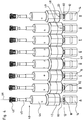
Figure 4 shows a schematic view of the vertical movement of the first section, whereinfigures 4A and 4H depict the upper position andfigures 4D-4G depict the lower, engagement position. Infigure 4B and 4C the first section is also engaged, but not in its lower position. The skilled person will understand that the reorienting units are configured in a circular manner instead of the linear representation offigure 4 . -
Figure 4A shows the reorientingunit 40 in theupper position 48.Figure 4B shows theengagement member 42, theprotrusion 80 in contact with the upper side of the simulated cigarette part. Fromfigure 4B to figure 4C , the protrusion slides over the upper side of the part carried by the product carrier in a rotary manner. The protrusion keeps on rotating and sliding over the upper side until the protrusion is positioned exactly above themating shape 82, in this case a recess. The resilient member 47 (figure 5 ) forces the protrusion into the mating shape. This is shown infigure 4D and thefirst section 44 of the reorienting unit is in thelower position 49. -
Figures 11A-11D show more generally afirst mating part 81 provided on theengagement member 42. Infigure 11A thefirst mating part 81 is a protruding part, whereas thefirst mating part 81 infigure 11B is a recess. Both configurations are possible, as long as the simulated cigarette part has asecond mating part 83 at an upper side thereof which mates with the first mating part. If thefirst mating part 81 is protruding, then thesecond mating part 83 has at least a recess to accommodate the protruding part of thefist mating part 81, or vice versa. -
Figure 11A further shows thefirst mating shape 81 comprising a male or female centeringpart 84 configured to concentrically align the engagement member with the simulated cigarette part. This speeds up the engagement of the engagement member with the simulated cigarette part. It also increases the reliability. Acenter 85 of the first mating shape is located on thevertical unit axis 46. The centeringpart 84 protrudes beyond one ormore side protrusions 86, in the shown embodiment beyond twoside protrusions 86. The side protrusions 86 extend radially outward from thevertical unit axis 46. The male or female centering part is conical. - Next the reorienting unit, and thus the protrusion rotates due to the varying radius R of the
first cam track 52.Figures 4D to 4G show the reorienting of the simulated cigarette part.Figure 4G also shows the second, predeterminedorientation 20 of the part carried by the product carrier. With the part in the second, predetermined orientation, the reorienting unit arrives upstream from theupward slope section 72 of thesecond cam track 70, seefigure 1 . Due to the upward slope section the engagement member moves upwards and disengages the simulated cigarette part. This is shown infigure 4H . At this stage the part is in the second, predetermined orientation and the first section of the reorienting unit is in the upper position. - Turning to
figures 4 and5 , the reorientingunit 40 comprises afirst section 44 which moves between anupper position 48 and alower position 49. Aresilient member 47 in the form of a helical spring is provided in the reorienting unit and vertically displaces the first section and biases the first section in a downward direction. The resilient member acts on asecond section 45 of the reorienting unit. The second section is fixed in the direction of avertical unit axis 46. - Turning to
figures 9 and10 , the reorienting device further comprises a movingdevice 60 for moving the product carriers. The moving device consists of acircular track 62 that is located underneath the reorientingunits 40 and guides theproduct carriers 14 holding the simulated cigarette parts. The moving device comprises a plurality ofproduct carrier movers 64 which move the product carriers along the said circular track underneath the reorienting units. Theproduct carrier movers 64 are provided in a body which resembles a gear. - The product carriers are supported by the
circular track 62 and are only pushed forward in a horizontal direction by the moving device. - The
product carrier movers 64 maintain the angular position of the product carriers during the reorientation of the simulated cigarette part. The simulated cigarette parts are held by the product carriers. - The
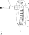
second cam track 70 as shown infigure 8 consists of anupward slope 72, a substantiallyhorizontal section 76 and adownward slope section 74. The reorienting units arrive at an upstream end of the upward slope section in thelower position 49 and in an engaged state with a simulated cigarette part. Subsequently, the reorienting units engage the upward slope section and are displaced upwards by the upward slope section. This causes a disengagement of the reorienting units from the simulated cigarette parts. The reorienting units are then guided over the substantially horizontal section located downstream from the upward slope section and upstream from the downward slope section. - During the movement along the substantially horizontal section the first section of the reorienting units are in the upper position. At the downward slope section, downstream from the substantially horizontal section, the first section of the reorienting units is vertically displaced in a downward direction as it travels along the downward slope section. This makes it possible to engage the first section of each reorienting unit with a next simulated cigarette part.
- The
first cam track 22 extends in a plane which is substantially perpendicular to the mainvertical rotation axis 24. The first cam track may be also stationary and/or endless. The second cam track is also stationary. However, the second cam track extends along a part of a trajectory of the reorienting units. - The rotary carrousel is intended to make a continuous movement in particular a rotary movement. This has the advantage of a high production rate.
- In operation the following steps are carried out:
- feeding product carriers to the (circular) track of the reorienting device, and moving the product carriers along said track, wherein each product carrier carries a simulated cigarette part;
- engaging the simulated cigarette part with the engagement member of the first section of each reorienting unit by a downward movement of the first section of the reorienting unit, and;
- rotating the simulated cigarette part relative to the product carrier by a rotary movement of the reorienting unit to the second, predetermined orientation.
- In the abovementioned steps:
- each cam is moved along the first cam track during the rotary movement of the carrousel, wherein the first cam track has a varying radius R causing a radial movement of the cam when the cam travels along the first cam track;
- each transmission gear attached to its respective cam rotates about its axis when the cam moves radially and engages the actuating gear of the reorienting unit and rotates the reorienting unit;
- In operation the vertical displacement of the first section of the reorienting unit involves the steps:
- a) moving the reorienting unit by the rotary support frame, wherein the first section of the reorienting unit is in the lower position and is engaged with a simulated cigarette part;
- b) moving the reorienting unit along the upward slope section of the second cam track, wherein the first section of each reorienting unit is moved upward and disengages from the simulated cigarette part;
- c) moving the reorienting unit along the substantially horizontal section of the second cam track, wherein the first section of each reorienting unit is in the upper position and not engaged with any simulated cigarette part;
- d) moving the reorienting unit along the downward slope section, wherein the first section of each reorienting unit is vertically displaced in a downward direction as it moves along the downward slope section and engages a new simulated cigarette part;
- e) moving the reorienting unit further along the track and rotating the reorienting unit, and subsequently reorienting the simulated cigarette part.
- The abovementioned step e) comprises pressing the protrusion into a recess of the simulated cigarette part. The pressing is achieved due to the force of the resilient member. Thereby the lowest position of the first section of the reorienting unit is reached. In case the engagement member has a recess and the simulated cigarette part has a protrusion, a skilled person will understand the recess is pressed over the protrusion.
- In operation, the first angular orientation of the simulated cigarette parts is arbitrary. The engagement member engages the simulated cigarette part carried by a product carrier. After engaging, the simulated cigarette part is rotated relative to the product carrier. So the following steps are carried out:
- sliding the engagement member over the upper surface of the simulated cigarette part in a rotary manner until the engagement member fits into or over a mating shape of the simulated cigarette part, and
- pressing the engagement member into or over the mating shape by the force of the resilient member, and
- subsequently rotating the simulated cigarette part relative to the product carrier.
- During the rotary movement of the reorienting units about the main vertical rotation axis, the first section of the reorienting units is displaced vertically.
- It will be recognised that an embodiment may not achieve all of the stated objects.
- As required, detailed embodiments of the present invention are disclosed herein; however, it is to be understood that the disclosed embodiments are merely exemplary of the invention, which can be embodied in various forms. Therefore, specific structural and functional details disclosed herein are not to be interpreted as limiting, but merely as a basis for the claims and as a representative basis for teaching one skilled in the art to variously employ the present invention in virtually any appropriately detailed structure. Further, the terms and phrases used herein are not intended to be limiting, but rather, to provide an understandable description of the invention.
- The terms "a" or "an", as used herein, defined as one or more than one. The term plurality, as used herein, is defined as two or more than two. The term another, as used herein, is defined as at least a second or more. The terms including and/or having, as used herein, are defined as comprising (i.e., open language, not excluding other elements or steps). Any reference signs in the claims should not be construed as limiting the scope of the claims or the invention.
- The mere fact that certain measures are recited in mutually different dependent claims does not indicate that a combination of these measures cannot be used to advantage.
Claims (15)
- Reorienting device (10) for reorienting simulated cigarette parts (12) which are carried by a product carrier (14) about a vertical product axis (16) from a first angular orientation (18) to a second, predetermined orientation (20) relative to said product carrier, wherein the device comprises:- a main vertical rotation axis (24);- a first cam track (22) extending at least partially around the main vertical rotation axis (24);- a rotary carrousel (30) configured to rotate about the main vertical rotation axis, the rotary carrousel comprising;∘ a rotary support frame (32);∘ a plurality of reorienting units (40) connected to the rotary support frame and arranged in a circular configuration when viewed in top view, each reorienting unit comprising an engagement member (42), wherein each engagement member is configured to engage the simulated cigarette part and to reorient it about a vertical product axis, wherein each reorienting unit comprises a first section (44) which is rotatable relative to the rotary support frame about a vertical unit axis (46) and is movable in a vertical direction between an upper position (48) and a lower position (49), the upper position being a retracted position and the lower position being an engagement position;∘ a plurality of transmission mechanisms (50) connected to the rotary support frame, each transmission mechanism being associated with a respective reorienting unit, each transmission mechanism comprising a cam (52) which moves along the first cam track during the rotation of the rotary support frame, wherein the transmission mechanisms convert a movement of the cam into a rotation of the first section of the reorienting unit about the vertical unit axis relative to the rotary support frame;- a moving device (60) for moving the product carriers, the moving device comprising:∘ a circular track (62) located underneath the reorienting units and configured to guide the product carriers which hold the simulated cigarette parts;∘ a plurality of product carrier movers (64) for moving the product carriers along the circular track underneath the reorienting units,- a second cam track (70) configured to vertically displace the first section of the reorienting units.
- Reorienting device according to claim 1, wherein the reorienting unit comprises:- the first section (44) which is movable between an upper position and a lower position and a second section (45) which is fixed in a direction of the vertical unit axis;- a resilient member (47) configured to vertically displace the first section and to bias the first section in a downward direction.
- Reorienting device according to any of the preceding claims, wherein the first cam track has a varying radius (R) relative to the main axis of rotation configured to cause a radial movement of the cam when the cam travels along the first cam track during the rotary movement of the rotary carrousel.
- Reorienting device according to any of the preceding claims, wherein each transmission mechanism comprises a transmission gear (54) which is attached to the cam, and wherein each reorienting unit comprises an actuating gear (41) which extends around the unit axis and engages the transmission gear (54) of the transmission mechanism.
- Reorienting device according to claim 4, wherein a radial movement of the cam results in a movement of the transmission gear, and results in turn in a movement of the actuating gear.
- Reorienting device according to any of the preceding claims, wherein the second cam track (70) comprises:- an upward slope section (72), wherein each reorienting unit is configured to arrive at an upstream end of the upward slope section in a lower position and in an engaged state with a simulated cigarette part, wherein the reorienting units are configured to engage the upward slope section and are moved upwards by the upward slope section, thereby causing a disengagement of the reorienting units from the simulated cigarette part;- a downward slope section (74) located downstream from the upward slope section, wherein the downward slope section is configured to displace the first section of each reorienting unit in a downward direction in order to engage the first section of each reorienting unit with a next simulated cigarette part.
- Reorienting device according to any of the preceding claims, wherein the first and second cam tracks are stationary.
- Reorienting device according to any of the preceding claims, wherein the rotary carrousel is configured to make a continuous movement, in particular a rotary movement.
- Reorienting device according to any of the preceding claims, wherein the first section comprises the engagement member which comprises a first mating part (81) configured to engage a second mating part (83) provided at the upper side of the simulated cigarette part.
- Reorienting device according to the previous claim, wherein the first mating part comprises a male or female centering part (84) configured to concentrically align the engagement member with the simulated cigarette part, wherein a center (85) of the first mating part is located on the vertical unit axis (46), and wherein the centering part protrudes beyond one or more side protrusions (86), which one or more side protrusions extend radially outward from the vertical unit axis (46).
- Reorienting device according to the previous claim, wherein the male or female centering part is conical.
- Reorienting device according to any of the claims 9-11, wherein the first section comprises the engagement member which comprises a protrusion (80) configured to engage the mating shape (82) provided in the upper side of the simulated cigarette part.
- Reorienting device according to any of the preceding claims, wherein the first angular orientation of the simulated cigarette parts is arbitrary and wherein the engagement member is configured to:- engage simulated cigarette part and- slide over the upper surface of the simulated cigarette part in a rotary manner until it fits into or over the mating shape of the simulated cigarette part, and to- subsequently be pressed into or over the mating shape by the force of the resilient member, and to- subsequently rotate the simulated cigarette part relative to the product carrier.
- Reorienting device according to any of the preceding claims, wherein the product carrier movers are constructed to maintain the angular position of the product carriers when the simulated cigarette parts which are held by the product carriers are reoriented.
- Method for reorienting simulated cigarette parts, the method comprising:- feeding product carriers to the track of the reorienting device according to any of the preceding claims, and moving the product carriers along said track, wherein each product carrier carries a simulated cigarette part;- engaging the simulated cigarette part with the engagement member of the first section of a reorienting unit by a downward movement of the first section of the reorienting unit, and;- rotating the simulated cigarette part relative to the product carrier by a rotary movement of the reorienting unit to the second, predetermined orientation.
Priority Applications (1)
| Application Number | Priority Date | Filing Date | Title |
|---|---|---|---|
| PL17754813T PL3487329T3 (en) | 2016-07-20 | 2017-07-18 | Simulated cigarette parts reorienting apparatus |
Applications Claiming Priority (2)
| Application Number | Priority Date | Filing Date | Title |
|---|---|---|---|
| NL2017196A NL2017196B1 (en) | 2016-07-20 | 2016-07-20 | Simulated cigarette parts reorienting apparatus |
| PCT/NL2017/050484 WO2018016950A1 (en) | 2016-07-20 | 2017-07-18 | Simulated cigarette parts reorienting apparatus |
Publications (2)
| Publication Number | Publication Date |
|---|---|
| EP3487329A1 EP3487329A1 (en) | 2019-05-29 |
| EP3487329B1 true EP3487329B1 (en) | 2020-09-02 |
Family
ID=56852374
Family Applications (1)
| Application Number | Title | Priority Date | Filing Date |
|---|---|---|---|
| EP17754813.8A Active EP3487329B1 (en) | 2016-07-20 | 2017-07-18 | Simulated cigarette parts reorienting apparatus |
Country Status (7)
| Country | Link |
|---|---|
| US (1) | US10583997B2 (en) |
| EP (1) | EP3487329B1 (en) |
| JP (1) | JP6929348B2 (en) |
| ES (1) | ES2836288T3 (en) |
| NL (1) | NL2017196B1 (en) |
| PL (1) | PL3487329T3 (en) |
| WO (1) | WO2018016950A1 (en) |
Families Citing this family (2)
| Publication number | Priority date | Publication date | Assignee | Title |
|---|---|---|---|---|
| CA3105439A1 (en) | 2018-07-19 | 2020-01-23 | Sluis Cigar Machinery B.V. | A system for performing a processing step on device parts of simulated smoking devices, such as electronic cigarettes |
| CN109759345A (en) * | 2019-02-25 | 2019-05-17 | 深圳市卓茂科技有限公司 | A kind of x-ray detection device |
Citations (23)
| Publication number | Priority date | Publication date | Assignee | Title |
|---|---|---|---|---|
| US3119482A (en) | 1960-08-03 | 1964-01-28 | Continental Can Co | Method and machine for positioning articles to be packaged |
| DE2362727A1 (en) | 1972-12-18 | 1974-06-20 | Azionaria Costruzioni | DEVICE FOR ARRANGING ITEMS ARRIVING DISORDERED ON A DELIVERY CONVEYOR IN A DETERMINED ORDER ON A RECEIVING CONVEYOR |
| US4656817A (en) | 1986-01-10 | 1987-04-14 | Advalloy, Inc. | Apparatus for loading singulated lead frames into containers |
| DE3728291A1 (en) | 1987-08-25 | 1989-03-09 | Wilhelm Goetz | Process and apparatus for arranging and holding a plurality of pack units in a common receiving container |
| DE4102028A1 (en) | 1990-03-07 | 1991-09-12 | Cavanna Spa | CONVEYOR |
| EP0486439B1 (en) | 1990-11-14 | 1994-03-02 | Maurizio Marchesini | Device for synchronously driving the dispensing and the container handling means in bottling machines |
| EP0486440B1 (en) | 1990-11-14 | 1994-06-08 | Maurizio Marchesini | Device for dispensing liquid products to rotating elements, especially in bottling machines |
| US5581975A (en) | 1993-12-24 | 1996-12-10 | I.M.A. Industria Macchine Automatiche S.P.A. | Automatic machine for filling and closing flasks or the like containers |
| DE69720078T2 (en) | 1996-09-11 | 2004-04-01 | Pure Technology of St. Cloud, Inc., St. Cloud | METHOD AND DEVICE FOR TRANSFERRING OBJECTS FROM A BUCKET OR CONVEYOR TO A TAPE |
| DE69819089T2 (en) | 1997-08-05 | 2004-07-22 | Azionaria Costruzioni Macchine Automatiche A.C.M.A. S.P.A. | Conveyor system for the transport of goods |
| US6779651B1 (en) | 1999-12-13 | 2004-08-24 | Sidel | Device for conveying discrete entities having an improved transfer arm, and container blow-molding facility with such a device |
| DE60009594T2 (en) | 1999-04-29 | 2005-04-14 | Klöckner Hänsel Tevopharm B.V. | Rotatable gripping device |
| US20050103399A1 (en) | 2003-09-30 | 2005-05-19 | Volker Till | Beverage bottling plant for filling bottles with a liquid beverage filling material, having a transfer device for the transfer of containers from a transfer starwheel to the carousel of a container handling machine |
| DE202005006755U1 (en) | 2005-04-26 | 2005-10-20 | Khs Maschinen- Und Anlagenbau Ag | Labeling machine for jars, bottles or cartons with optically readable closures reads code on closure and orients containers so that label is always fitted in same position |
| EP1460028B1 (en) | 2003-03-19 | 2006-09-06 | Luciano Salda | Rotary sterilizing and filling machine |
| EP1889802A2 (en) | 2006-08-14 | 2008-02-20 | Neri S.p.A. | Carrousel device for conveying containers |
| US20090095371A1 (en) | 2003-11-10 | 2009-04-16 | Alois Monzel | Method of filling kegs with a liquid beverage in a keg filling plant |
| DE102009005180A1 (en) | 2009-01-15 | 2010-07-22 | Khs Ag | Container handling machine |
| WO2012077147A1 (en) | 2010-12-10 | 2012-06-14 | Sidel S.P.A. | Article -handling machine |
| EP2465814A1 (en) | 2010-12-16 | 2012-06-20 | Krones AG | Device for handling containers with container orientation |
| US20150083550A1 (en) | 2013-09-20 | 2015-03-26 | Morrison Timing Screw Co., dba Morrison Container Handling Solutions, Inc. | Rotary orienter |
| EP3012086A1 (en) | 2013-06-21 | 2016-04-27 | Nissei Asb Machine Co., Ltd. | Conveyance device |
| WO2016105191A1 (en) | 2014-12-23 | 2016-06-30 | Sluis Cigar Machinery B.V. | Device for filling cartridges of e-cigarettes with a liquid |
Family Cites Families (7)
| Publication number | Priority date | Publication date | Assignee | Title |
|---|---|---|---|---|
| US4174775A (en) * | 1977-04-20 | 1979-11-20 | Eli Lilly And Company | Apparatus for continuously orienting plastic and other types of bottles |
| DE4019031C2 (en) * | 1990-06-14 | 1996-08-01 | Tetra Pak Gmbh | Device for rotating workpiece carriers with workpieces transported by means of a conveyor and use of such a device |
| US8136651B2 (en) * | 2007-12-14 | 2012-03-20 | The Procter & Gamble Company | Method and apparatus for orienting articles |
| WO2015177055A1 (en) * | 2014-05-21 | 2015-11-26 | Sacmi Verona S.P.A. | Carousel for processing containers |
| WO2016083920A2 (en) * | 2014-11-27 | 2016-06-02 | Makro Labelling S.R.L. | Machine for moving containers to be processed |
| DE202017105383U1 (en) * | 2016-09-19 | 2017-09-18 | Ct Pack S.R.L. | Transfer unit for transferring articles between two lines arranged at an angle to one another |
| US10273092B2 (en) * | 2016-11-07 | 2019-04-30 | R.A Jones & Co. | Apparatus and methods for product orientation and hole healing applications |
-
2016
- 2016-07-20 NL NL2017196A patent/NL2017196B1/en not_active IP Right Cessation
-
2017
- 2017-07-18 JP JP2019502249A patent/JP6929348B2/en active Active
- 2017-07-18 US US16/317,878 patent/US10583997B2/en not_active Expired - Fee Related
- 2017-07-18 EP EP17754813.8A patent/EP3487329B1/en active Active
- 2017-07-18 PL PL17754813T patent/PL3487329T3/en unknown
- 2017-07-18 ES ES17754813T patent/ES2836288T3/en active Active
- 2017-07-18 WO PCT/NL2017/050484 patent/WO2018016950A1/en unknown
Patent Citations (23)
| Publication number | Priority date | Publication date | Assignee | Title |
|---|---|---|---|---|
| US3119482A (en) | 1960-08-03 | 1964-01-28 | Continental Can Co | Method and machine for positioning articles to be packaged |
| DE2362727A1 (en) | 1972-12-18 | 1974-06-20 | Azionaria Costruzioni | DEVICE FOR ARRANGING ITEMS ARRIVING DISORDERED ON A DELIVERY CONVEYOR IN A DETERMINED ORDER ON A RECEIVING CONVEYOR |
| US4656817A (en) | 1986-01-10 | 1987-04-14 | Advalloy, Inc. | Apparatus for loading singulated lead frames into containers |
| DE3728291A1 (en) | 1987-08-25 | 1989-03-09 | Wilhelm Goetz | Process and apparatus for arranging and holding a plurality of pack units in a common receiving container |
| DE4102028A1 (en) | 1990-03-07 | 1991-09-12 | Cavanna Spa | CONVEYOR |
| EP0486439B1 (en) | 1990-11-14 | 1994-03-02 | Maurizio Marchesini | Device for synchronously driving the dispensing and the container handling means in bottling machines |
| EP0486440B1 (en) | 1990-11-14 | 1994-06-08 | Maurizio Marchesini | Device for dispensing liquid products to rotating elements, especially in bottling machines |
| US5581975A (en) | 1993-12-24 | 1996-12-10 | I.M.A. Industria Macchine Automatiche S.P.A. | Automatic machine for filling and closing flasks or the like containers |
| DE69720078T2 (en) | 1996-09-11 | 2004-04-01 | Pure Technology of St. Cloud, Inc., St. Cloud | METHOD AND DEVICE FOR TRANSFERRING OBJECTS FROM A BUCKET OR CONVEYOR TO A TAPE |
| DE69819089T2 (en) | 1997-08-05 | 2004-07-22 | Azionaria Costruzioni Macchine Automatiche A.C.M.A. S.P.A. | Conveyor system for the transport of goods |
| DE60009594T2 (en) | 1999-04-29 | 2005-04-14 | Klöckner Hänsel Tevopharm B.V. | Rotatable gripping device |
| US6779651B1 (en) | 1999-12-13 | 2004-08-24 | Sidel | Device for conveying discrete entities having an improved transfer arm, and container blow-molding facility with such a device |
| EP1460028B1 (en) | 2003-03-19 | 2006-09-06 | Luciano Salda | Rotary sterilizing and filling machine |
| US20050103399A1 (en) | 2003-09-30 | 2005-05-19 | Volker Till | Beverage bottling plant for filling bottles with a liquid beverage filling material, having a transfer device for the transfer of containers from a transfer starwheel to the carousel of a container handling machine |
| US20090095371A1 (en) | 2003-11-10 | 2009-04-16 | Alois Monzel | Method of filling kegs with a liquid beverage in a keg filling plant |
| DE202005006755U1 (en) | 2005-04-26 | 2005-10-20 | Khs Maschinen- Und Anlagenbau Ag | Labeling machine for jars, bottles or cartons with optically readable closures reads code on closure and orients containers so that label is always fitted in same position |
| EP1889802A2 (en) | 2006-08-14 | 2008-02-20 | Neri S.p.A. | Carrousel device for conveying containers |
| DE102009005180A1 (en) | 2009-01-15 | 2010-07-22 | Khs Ag | Container handling machine |
| WO2012077147A1 (en) | 2010-12-10 | 2012-06-14 | Sidel S.P.A. | Article -handling machine |
| EP2465814A1 (en) | 2010-12-16 | 2012-06-20 | Krones AG | Device for handling containers with container orientation |
| EP3012086A1 (en) | 2013-06-21 | 2016-04-27 | Nissei Asb Machine Co., Ltd. | Conveyance device |
| US20150083550A1 (en) | 2013-09-20 | 2015-03-26 | Morrison Timing Screw Co., dba Morrison Container Handling Solutions, Inc. | Rotary orienter |
| WO2016105191A1 (en) | 2014-12-23 | 2016-06-30 | Sluis Cigar Machinery B.V. | Device for filling cartridges of e-cigarettes with a liquid |
Also Published As
| Publication number | Publication date |
|---|---|
| US20190152717A1 (en) | 2019-05-23 |
| NL2017196B1 (en) | 2018-01-26 |
| PL3487329T3 (en) | 2021-04-19 |
| JP2019524102A (en) | 2019-09-05 |
| US10583997B2 (en) | 2020-03-10 |
| WO2018016950A1 (en) | 2018-01-25 |
| JP6929348B2 (en) | 2021-09-01 |
| EP3487329A1 (en) | 2019-05-29 |
| ES2836288T3 (en) | 2021-06-24 |
Similar Documents
| Publication | Publication Date | Title |
|---|---|---|
| EP3487329B1 (en) | Simulated cigarette parts reorienting apparatus | |
| JP6032418B2 (en) | Linear conveyor | |
| CN113260585B (en) | Device for grouping containers | |
| EP2499069A1 (en) | Unscrambling machine for containers and relative process | |
| US11535458B2 (en) | Apparatus, system and method for orientating articles | |
| US20100200362A1 (en) | Device for loading containers on a transporting element provided with means for ejecting incorrectly loaded containers | |
| CN108264005B (en) | full-automatic bottle conveying assembly line | |
| EP3549744B1 (en) | Oven for preforms | |
| US3551993A (en) | Machine and method for handling workpieces | |
| EP2846756B1 (en) | Apparatus for feeding capsules | |
| US3336723A (en) | Machine for assembling containers with clips | |
| GB2168942A (en) | Machine for placing sleeves around objects of elongate form | |
| US10065805B2 (en) | Molded article supply apparatus | |
| WO2018016953A2 (en) | Product carrier | |
| CN109367850B (en) | Capping machine for cup-packaged beverage | |
| GB1297572A (en) | ||
| CN216035341U (en) | Bottle separating mechanism for beverage packaging | |
| EP2377763A1 (en) | Apparatus and method for turning eggs | |
| EP3037356A1 (en) | A forming apparatus for forming a base of a container | |
| US9771175B2 (en) | Labelling unit for applying a label onto an article | |
| CN113478194B (en) | High-speed lid machine that closes of disjunctor lid | |
| JP2016003125A (en) | Article alignment device | |
| CN113772155A (en) | Bottle dividing mechanism and method for beverage packaging | |
| JPH06234418A (en) | Article taking-out device having arrangement mechanism | |
| JP6553944B2 (en) | Alignment apparatus, alignment system, and alignment method |
Legal Events
| Date | Code | Title | Description |
|---|---|---|---|
| STAA | Information on the status of an ep patent application or granted ep patent |
Free format text: STATUS: UNKNOWN |
|
| STAA | Information on the status of an ep patent application or granted ep patent |
Free format text: STATUS: THE INTERNATIONAL PUBLICATION HAS BEEN MADE |
|
| PUAI | Public reference made under article 153(3) epc to a published international application that has entered the european phase |
Free format text: ORIGINAL CODE: 0009012 |
|
| STAA | Information on the status of an ep patent application or granted ep patent |
Free format text: STATUS: REQUEST FOR EXAMINATION WAS MADE |
|
| 17P | Request for examination filed |
Effective date: 20190118 |
|
| AK | Designated contracting states |
Kind code of ref document: A1 Designated state(s): AL AT BE BG CH CY CZ DE DK EE ES FI FR GB GR HR HU IE IS IT LI LT LU LV MC MK MT NL NO PL PT RO RS SE SI SK SM TR |
|
| AX | Request for extension of the european patent |
Extension state: BA ME |
|
| DAV | Request for validation of the european patent (deleted) | ||
| DAX | Request for extension of the european patent (deleted) | ||
| REG | Reference to a national code |
Ref country code: DE Ref legal event code: R079 Ref document number: 602017022896 Country of ref document: DE Free format text: PREVIOUS MAIN CLASS: A24F0047000000 Ipc: A24F0040700000 |
|
| GRAP | Despatch of communication of intention to grant a patent |
Free format text: ORIGINAL CODE: EPIDOSNIGR1 |
|
| STAA | Information on the status of an ep patent application or granted ep patent |
Free format text: STATUS: GRANT OF PATENT IS INTENDED |
|
| RIC1 | Information provided on ipc code assigned before grant |
Ipc: A24F 40/70 20200101AFI20200130BHEP |
|
| INTG | Intention to grant announced |
Effective date: 20200221 |
|
| GRAS | Grant fee paid |
Free format text: ORIGINAL CODE: EPIDOSNIGR3 |
|
| GRAA | (expected) grant |
Free format text: ORIGINAL CODE: 0009210 |
|
| STAA | Information on the status of an ep patent application or granted ep patent |
Free format text: STATUS: THE PATENT HAS BEEN GRANTED |
|
| AK | Designated contracting states |
Kind code of ref document: B1 Designated state(s): AL AT BE BG CH CY CZ DE DK EE ES FI FR GB GR HR HU IE IS IT LI LT LU LV MC MK MT NL NO PL PT RO RS SE SI SK SM TR |
|
| REG | Reference to a national code |
Ref country code: GB Ref legal event code: FG4D |
|
| REG | Reference to a national code |
Ref country code: AT Ref legal event code: REF Ref document number: 1307760 Country of ref document: AT Kind code of ref document: T Effective date: 20200915 Ref country code: CH Ref legal event code: EP |
|
| REG | Reference to a national code |
Ref country code: DE Ref legal event code: R096 Ref document number: 602017022896 Country of ref document: DE |
|
| REG | Reference to a national code |
Ref country code: IE Ref legal event code: FG4D |
|
| REG | Reference to a national code |
Ref country code: LT Ref legal event code: MG4D |
|
| PG25 | Lapsed in a contracting state [announced via postgrant information from national office to epo] |
Ref country code: SE Free format text: LAPSE BECAUSE OF FAILURE TO SUBMIT A TRANSLATION OF THE DESCRIPTION OR TO PAY THE FEE WITHIN THE PRESCRIBED TIME-LIMIT Effective date: 20200902 Ref country code: HR Free format text: LAPSE BECAUSE OF FAILURE TO SUBMIT A TRANSLATION OF THE DESCRIPTION OR TO PAY THE FEE WITHIN THE PRESCRIBED TIME-LIMIT Effective date: 20200902 Ref country code: NO Free format text: LAPSE BECAUSE OF FAILURE TO SUBMIT A TRANSLATION OF THE DESCRIPTION OR TO PAY THE FEE WITHIN THE PRESCRIBED TIME-LIMIT Effective date: 20201202 Ref country code: GR Free format text: LAPSE BECAUSE OF FAILURE TO SUBMIT A TRANSLATION OF THE DESCRIPTION OR TO PAY THE FEE WITHIN THE PRESCRIBED TIME-LIMIT Effective date: 20201203 Ref country code: FI Free format text: LAPSE BECAUSE OF FAILURE TO SUBMIT A TRANSLATION OF THE DESCRIPTION OR TO PAY THE FEE WITHIN THE PRESCRIBED TIME-LIMIT Effective date: 20200902 Ref country code: BG Free format text: LAPSE BECAUSE OF FAILURE TO SUBMIT A TRANSLATION OF THE DESCRIPTION OR TO PAY THE FEE WITHIN THE PRESCRIBED TIME-LIMIT Effective date: 20201202 Ref country code: LT Free format text: LAPSE BECAUSE OF FAILURE TO SUBMIT A TRANSLATION OF THE DESCRIPTION OR TO PAY THE FEE WITHIN THE PRESCRIBED TIME-LIMIT Effective date: 20200902 |
|
| REG | Reference to a national code |
Ref country code: NL Ref legal event code: MP Effective date: 20200902 |
|
| REG | Reference to a national code |
Ref country code: AT Ref legal event code: MK05 Ref document number: 1307760 Country of ref document: AT Kind code of ref document: T Effective date: 20200902 |
|
| PG25 | Lapsed in a contracting state [announced via postgrant information from national office to epo] |
Ref country code: LV Free format text: LAPSE BECAUSE OF FAILURE TO SUBMIT A TRANSLATION OF THE DESCRIPTION OR TO PAY THE FEE WITHIN THE PRESCRIBED TIME-LIMIT Effective date: 20200902 Ref country code: RS Free format text: LAPSE BECAUSE OF FAILURE TO SUBMIT A TRANSLATION OF THE DESCRIPTION OR TO PAY THE FEE WITHIN THE PRESCRIBED TIME-LIMIT Effective date: 20200902 |
|
| PG25 | Lapsed in a contracting state [announced via postgrant information from national office to epo] |
Ref country code: EE Free format text: LAPSE BECAUSE OF FAILURE TO SUBMIT A TRANSLATION OF THE DESCRIPTION OR TO PAY THE FEE WITHIN THE PRESCRIBED TIME-LIMIT Effective date: 20200902 Ref country code: SM Free format text: LAPSE BECAUSE OF FAILURE TO SUBMIT A TRANSLATION OF THE DESCRIPTION OR TO PAY THE FEE WITHIN THE PRESCRIBED TIME-LIMIT Effective date: 20200902 Ref country code: CZ Free format text: LAPSE BECAUSE OF FAILURE TO SUBMIT A TRANSLATION OF THE DESCRIPTION OR TO PAY THE FEE WITHIN THE PRESCRIBED TIME-LIMIT Effective date: 20200902 Ref country code: PT Free format text: LAPSE BECAUSE OF FAILURE TO SUBMIT A TRANSLATION OF THE DESCRIPTION OR TO PAY THE FEE WITHIN THE PRESCRIBED TIME-LIMIT Effective date: 20210104 Ref country code: RO Free format text: LAPSE BECAUSE OF FAILURE TO SUBMIT A TRANSLATION OF THE DESCRIPTION OR TO PAY THE FEE WITHIN THE PRESCRIBED TIME-LIMIT Effective date: 20200902 |
|
| PG25 | Lapsed in a contracting state [announced via postgrant information from national office to epo] |
Ref country code: AL Free format text: LAPSE BECAUSE OF FAILURE TO SUBMIT A TRANSLATION OF THE DESCRIPTION OR TO PAY THE FEE WITHIN THE PRESCRIBED TIME-LIMIT Effective date: 20200902 Ref country code: AT Free format text: LAPSE BECAUSE OF FAILURE TO SUBMIT A TRANSLATION OF THE DESCRIPTION OR TO PAY THE FEE WITHIN THE PRESCRIBED TIME-LIMIT Effective date: 20200902 Ref country code: IS Free format text: LAPSE BECAUSE OF FAILURE TO SUBMIT A TRANSLATION OF THE DESCRIPTION OR TO PAY THE FEE WITHIN THE PRESCRIBED TIME-LIMIT Effective date: 20210102 |
|
| REG | Reference to a national code |
Ref country code: DE Ref legal event code: R026 Ref document number: 602017022896 Country of ref document: DE |
|
| PLBI | Opposition filed |
Free format text: ORIGINAL CODE: 0009260 |
|
| PLAX | Notice of opposition and request to file observation + time limit sent |
Free format text: ORIGINAL CODE: EPIDOSNOBS2 |
|
| REG | Reference to a national code |
Ref country code: ES Ref legal event code: FG2A Ref document number: 2836288 Country of ref document: ES Kind code of ref document: T3 Effective date: 20210624 |
|
| PG25 | Lapsed in a contracting state [announced via postgrant information from national office to epo] |
Ref country code: SK Free format text: LAPSE BECAUSE OF FAILURE TO SUBMIT A TRANSLATION OF THE DESCRIPTION OR TO PAY THE FEE WITHIN THE PRESCRIBED TIME-LIMIT Effective date: 20200902 |
|
| 26 | Opposition filed |
Opponent name: SEEMANN & PARTNER PATENTANWAELTE MBB Effective date: 20210602 |
|
| PG25 | Lapsed in a contracting state [announced via postgrant information from national office to epo] |
Ref country code: SI Free format text: LAPSE BECAUSE OF FAILURE TO SUBMIT A TRANSLATION OF THE DESCRIPTION OR TO PAY THE FEE WITHIN THE PRESCRIBED TIME-LIMIT Effective date: 20200902 Ref country code: DK Free format text: LAPSE BECAUSE OF FAILURE TO SUBMIT A TRANSLATION OF THE DESCRIPTION OR TO PAY THE FEE WITHIN THE PRESCRIBED TIME-LIMIT Effective date: 20200902 |
|
| PLBB | Reply of patent proprietor to notice(s) of opposition received |
Free format text: ORIGINAL CODE: EPIDOSNOBS3 |
|
| REG | Reference to a national code |
Ref country code: CH Ref legal event code: PL |
|
| PG25 | Lapsed in a contracting state [announced via postgrant information from national office to epo] |
Ref country code: MC Free format text: LAPSE BECAUSE OF FAILURE TO SUBMIT A TRANSLATION OF THE DESCRIPTION OR TO PAY THE FEE WITHIN THE PRESCRIBED TIME-LIMIT Effective date: 20200902 |
|
| REG | Reference to a national code |
Ref country code: BE Ref legal event code: MM Effective date: 20210731 |
|
| PG25 | Lapsed in a contracting state [announced via postgrant information from national office to epo] |
Ref country code: LI Free format text: LAPSE BECAUSE OF NON-PAYMENT OF DUE FEES Effective date: 20210731 Ref country code: CH Free format text: LAPSE BECAUSE OF NON-PAYMENT OF DUE FEES Effective date: 20210731 |
|
| PG25 | Lapsed in a contracting state [announced via postgrant information from national office to epo] |
Ref country code: LU Free format text: LAPSE BECAUSE OF NON-PAYMENT OF DUE FEES Effective date: 20210718 |
|
| REG | Reference to a national code |
Ref country code: DE Ref legal event code: R100 Ref document number: 602017022896 Country of ref document: DE |
|
| PLBP | Opposition withdrawn |
Free format text: ORIGINAL CODE: 0009264 |
|
| PG25 | Lapsed in a contracting state [announced via postgrant information from national office to epo] |
Ref country code: IE Free format text: LAPSE BECAUSE OF NON-PAYMENT OF DUE FEES Effective date: 20210718 Ref country code: BE Free format text: LAPSE BECAUSE OF NON-PAYMENT OF DUE FEES Effective date: 20210731 |
|
| PLBD | Termination of opposition procedure: decision despatched |
Free format text: ORIGINAL CODE: EPIDOSNOPC1 |
|
| PGFP | Annual fee paid to national office [announced via postgrant information from national office to epo] |
Ref country code: IT Payment date: 20220728 Year of fee payment: 6 Ref country code: GB Payment date: 20220722 Year of fee payment: 6 Ref country code: DE Payment date: 20220720 Year of fee payment: 6 |
|
| PGFP | Annual fee paid to national office [announced via postgrant information from national office to epo] |
Ref country code: PL Payment date: 20220708 Year of fee payment: 6 Ref country code: FR Payment date: 20220722 Year of fee payment: 6 |
|
| PLBM | Termination of opposition procedure: date of legal effect published |
Free format text: ORIGINAL CODE: 0009276 |
|
| 27C | Opposition proceedings terminated |
Effective date: 20220712 |
|
| PGFP | Annual fee paid to national office [announced via postgrant information from national office to epo] |
Ref country code: ES Payment date: 20221020 Year of fee payment: 6 |
|
| P01 | Opt-out of the competence of the unified patent court (upc) registered |
Effective date: 20230522 |
|
| PG25 | Lapsed in a contracting state [announced via postgrant information from national office to epo] |
Ref country code: NL Free format text: LAPSE BECAUSE OF NON-PAYMENT OF DUE FEES Effective date: 20200923 Ref country code: CY Free format text: LAPSE BECAUSE OF FAILURE TO SUBMIT A TRANSLATION OF THE DESCRIPTION OR TO PAY THE FEE WITHIN THE PRESCRIBED TIME-LIMIT Effective date: 20200902 |
|
| PG25 | Lapsed in a contracting state [announced via postgrant information from national office to epo] |
Ref country code: HU Free format text: LAPSE BECAUSE OF FAILURE TO SUBMIT A TRANSLATION OF THE DESCRIPTION OR TO PAY THE FEE WITHIN THE PRESCRIBED TIME-LIMIT; INVALID AB INITIO Effective date: 20170718 |
|
| REG | Reference to a national code |
Ref country code: DE Ref legal event code: R119 Ref document number: 602017022896 Country of ref document: DE |
|
| GBPC | Gb: european patent ceased through non-payment of renewal fee |
Effective date: 20230718 |