JP6032418B2 - Linear conveyor - Google Patents
Linear conveyor Download PDFInfo
- Publication number
- JP6032418B2 JP6032418B2 JP2013001352A JP2013001352A JP6032418B2 JP 6032418 B2 JP6032418 B2 JP 6032418B2 JP 2013001352 A JP2013001352 A JP 2013001352A JP 2013001352 A JP2013001352 A JP 2013001352A JP 6032418 B2 JP6032418 B2 JP 6032418B2
- Authority
- JP
- Japan
- Prior art keywords
- mover
- linear motor
- motor control
- control section
- carton
- Prior art date
- Legal status (The legal status is an assumption and is not a legal conclusion. Google has not performed a legal analysis and makes no representation as to the accuracy of the status listed.)
- Active
Links
Images


Classifications
-
- B—PERFORMING OPERATIONS; TRANSPORTING
- B65—CONVEYING; PACKING; STORING; HANDLING THIN OR FILAMENTARY MATERIAL
- B65G—TRANSPORT OR STORAGE DEVICES, e.g. CONVEYORS FOR LOADING OR TIPPING, SHOP CONVEYOR SYSTEMS OR PNEUMATIC TUBE CONVEYORS
- B65G54/00—Non-mechanical conveyors not otherwise provided for
- B65G54/02—Non-mechanical conveyors not otherwise provided for electrostatic, electric, or magnetic
-
- B—PERFORMING OPERATIONS; TRANSPORTING
- B65—CONVEYING; PACKING; STORING; HANDLING THIN OR FILAMENTARY MATERIAL
- B65G—TRANSPORT OR STORAGE DEVICES, e.g. CONVEYORS FOR LOADING OR TIPPING, SHOP CONVEYOR SYSTEMS OR PNEUMATIC TUBE CONVEYORS
- B65G19/00—Conveyors comprising an impeller or a series of impellers carried by an endless traction element and arranged to move articles or materials over a supporting surface or underlying material, e.g. endless scraper conveyors
- B65G19/02—Conveyors comprising an impeller or a series of impellers carried by an endless traction element and arranged to move articles or materials over a supporting surface or underlying material, e.g. endless scraper conveyors for articles, e.g. for containers
-
- B—PERFORMING OPERATIONS; TRANSPORTING
- B65—CONVEYING; PACKING; STORING; HANDLING THIN OR FILAMENTARY MATERIAL
- B65G—TRANSPORT OR STORAGE DEVICES, e.g. CONVEYORS FOR LOADING OR TIPPING, SHOP CONVEYOR SYSTEMS OR PNEUMATIC TUBE CONVEYORS
- B65G35/00—Mechanical conveyors not otherwise provided for
- B65G35/06—Mechanical conveyors not otherwise provided for comprising a load-carrier moving along a path, e.g. a closed path, and adapted to be engaged by any one of a series of traction elements spaced along the path
Description
本発明はリニア搬送装置に関し、詳しくは循環通路に沿って設けた電磁石を制御して永久磁石を備えた可動子を移動させるリニア搬送装置に関する。 The present invention relates to a linear transport device, and more particularly to a linear transport device that moves an armature provided with a permanent magnet by controlling an electromagnet provided along a circulation path.
従来、無端状の循環通路と、当該循環通路に沿って循環走行する可動子と、上記循環通路に沿って設けた電磁石と、上記可動子に設けた永久磁石とを備え、上記電磁石を制御して上記可動子を上記循環通路に沿って移動させる制御手段とを備えたリニア搬送装置が知られている(特許文献1)。
上記特許文献1のリニア搬送装置では、上記循環通路における所定の位置に、上記電磁石によって可動子の加速または減速を行うリニアモータによる制御区間が設けられ、このリニアモータによる制御区間に隣接する区間では、上記可動子がレールに沿って滑走するようになっている。
Conventionally, an endless circulation path, a mover that circulates along the circulation path, an electromagnet provided along the circulation path, and a permanent magnet provided on the mover are provided to control the electromagnet. In addition, there is known a linear transport device including a control unit that moves the mover along the circulation path (Patent Document 1).
In the linear transport device of Patent Document 1, a control section by a linear motor that accelerates or decelerates the mover by the electromagnet is provided at a predetermined position in the circulation passage. In a section adjacent to the control section by the linear motor, The mover is adapted to slide along the rail.
しかしながら上記特許文献1のリニア搬送装置では、上記リニアモータによる制御区間以外では、上記可動子は自重等によってレールに沿って滑走するだけであり、その位置を制御できないという問題がある。
一方、循環通路の全周に電磁石を設ければ、各可動子の位置を制御可能となるが、可動子の位置を細かく制御する必要のない位置まで電磁石を設けることはリニア搬送装置が高コストになるという問題があった。
このような問題に鑑み、本発明は循環通路の全周において可動子の位置を制御することができ、かつ安価に製造可能なリニア搬送装置を提供するものである。
However, in the linear conveyance device of Patent Document 1, there is a problem in that the mover only slides along the rail by its own weight or the like other than the control section by the linear motor, and its position cannot be controlled.
On the other hand, if an electromagnet is provided on the entire circumference of the circulation path, the position of each mover can be controlled. However, providing the electromagnet to a position where the position of the mover does not need to be finely controlled is expensive for the linear transport device. There was a problem of becoming.
In view of such a problem, the present invention provides a linear conveyance device that can control the position of the mover over the entire circumference of the circulation passage and can be manufactured at low cost.
すなわち本発明は、無端状の循環通路と、当該循環通路に沿って循環走行する可動子と、上記循環通路に沿って設けた電磁石と、上記可動子に設けた永久磁石とを備え、上記電磁石を制御して上記可動子を上記循環通路に沿って移動させる制御手段とを備え、
上記循環通路における所定の区間を上記電磁石を設けたリニアモータ制御区間とし、上記リニアモータ制御区間以外の区間を電磁石を設けない非リニアモータ制御区間としたリニア搬送装置において、
上記可動子に被係合部材を設けるとともに、上記循環通路における非リニアモータ制御区間に、上記可動子の被係合部材に係合する係合部材と、当該係合部材を当該非リニアモータ制御区間に沿って移動させる駆動手段とを設け、
上記制御手段は上記リニアモータ制御区間における上記可動子の位置を認識し、上記可動子がリニアモータ制御区間から非リニアモータ制御区間に移行する際に、上記係合部材と上記可動子の被係合部材とが係合するように当該可動子または上記駆動手段の少なくともいずれか一方を制御することを特徴とするものである。
That is, the present invention includes an endless circulation path, a mover that circulates along the circulation path, an electromagnet provided along the circulation path, and a permanent magnet provided on the mover. And a control means for moving the mover along the circulation path by controlling
In the linear conveyance device, the predetermined section in the circulation path is a linear motor control section provided with the electromagnet, and the non-linear motor control section is provided with a section other than the linear motor control section,
An engaging member is provided on the mover, and an engaging member that engages with the engaged member of the mover in the non-linear motor control section in the circulation passage, and the engaging member is controlled by the non-linear motor control Drive means for moving along the section,
The control means recognizes the position of the mover in the linear motor control section, and when the mover moves from the linear motor control section to the non-linear motor control section, the engagement member and the mover are engaged. At least one of the movable element and the driving means is controlled so that the combined member is engaged.
上記構成によれば、可動子が非リニアモータ制御区間に移行しても、当該可動子の被係合部材に係合部材を係合させて、当該係合部材を駆動手段によって駆動させることで、上記可動子の位置を制御することが可能となる。
そして上記非リニアモータ制御区間には電磁石が設けられていないことから、リニア搬送装置を安価に製造することが可能となる。
According to the above configuration, even when the mover shifts to the non-linear motor control section, the engagement member is engaged with the engaged member of the mover, and the engagement member is driven by the driving unit. The position of the mover can be controlled.
And since the electromagnet is not provided in the said non-linear motor control area, it becomes possible to manufacture a linear conveyance apparatus cheaply.
以下図示実施例について説明すると、図1は本発明にかかるリニア搬送装置としてのカートン搬送装置1の側面図を示し、カートンCを搬送しながら成形するとともに、当該成形したカートンCを搬送しながら物品等を収容する装置となっている。
上記カートンCは環状に連結され、上方を向いた天面C1と、下方を向いた底面C2と、搬送方向下流側の前方を向いた前面C3と、搬送方向上流側の後方を向いた後面C4とを有し、これら各面にはそれぞれカートンCの側部開口を閉鎖するための図示しないフラップが連結されている。
また上記カートンCは、上記前面C3および後面C4が倒れて扁平状となった成形前の状態で供給され、これら前面C3および後面C4を起立させて底面C2および天面C1を相互に離隔させることで、略長方形に位置した成形状態とすることができる。
上記カートン搬送装置1は、上記成形前のカートンCを収容したカートンマガジン2と、上記カートンCを支持する搬送面3と、上記カートンマガジン2から成形前のカートンCを取り出してこれを上記搬送面3に載置するカートン供給手段4と、上記搬送面3の下方に設けられて上記カートンCの底面C2を吸着保持する下側吸着手段5と、上記搬送面3上でカートンCを成形し、かつ当該成形状態のカートンCを搬送する成形搬送手段6とを備え、これらは図示しない制御手段によって制御されるようになっている。
FIG. 1 shows a side view of a carton conveying device 1 as a linear conveying device according to the present invention, in which a carton C is molded while being conveyed and an article is conveyed while the molded carton C is conveyed. It is a device that accommodates etc.
The carton C is connected in an annular shape, and has a top surface C1 facing upward, a bottom surface C2 facing downward, a front surface C3 facing forward on the downstream side in the transport direction, and a rear surface C4 facing backward on the upstream side in the transport direction. Each of these surfaces is connected to a flap (not shown) for closing the side opening of the carton C.
In addition, the carton C is supplied in a state before molding in which the front surface C3 and the rear surface C4 are inclined and flattened, and the front surface C3 and the rear surface C4 are raised to separate the bottom surface C2 and the top surface C1 from each other. Thus, it can be in a molded state located in a substantially rectangular shape.
The carton transport device 1 includes a carton magazine 2 that accommodates the carton C before molding, a
上記カートンマガジン2には、成形前のカートンCが複数積層した状態で保持されており、その下端部に位置したカートンCから順に、上記カートン供給手段4が吸着保持するようになっている。
上記搬送面3は平滑に形成されており、上記カートン供給手段4が供給したカートンCは上記成形搬送手段6によってこの搬送面3に摺接しながら搬送され、図示しない下流側には、上記カートンCのフラップを閉鎖する工程や、カートンCに物品を収容する工程等が設定されている。
本実施例において、上記扁平な状態とされた成形前のカートンCは、天面C1および後面C4が上方を、上記底面C2および前面C3が下方を向いた状態で搬送面3に供給されるようになっている。
上記カートン供給手段4は、図示しない移動手段によって移動する構成を有し、上記カートンマガジン2の下端部に位置するカートンCの天面C1を吸着保持するとともに、これを底面C2が下方となるように上記搬送面3に載置するようになっている。
上記下側吸着手段5は、搬送面3の下方に設けられるとともに図示しない移動手段によって移動可能となっており、成形前のカートンCが搬送面3に載置されると、その底面C2を吸着保持し、その状態でカートンCが搬送面3を移動するのに同期して下流側に移動するようになっている。
The carton magazine 2 holds a plurality of pre-molded cartons C in a stacked state, and the carton supply means 4 sucks and holds them in order from the carton C located at the lower end thereof.
The
In the present embodiment, the flat carton C is supplied to the
The carton supply means 4 is configured to move by a moving means (not shown), holds the top surface C1 of the carton C located at the lower end of the carton magazine 2 and holds the top face C2 downward. Is placed on the
The
上記成形搬送手段6は、その一部が上記搬送面3に沿って設けられた無端状の循環通路11と、当該循環通路11に沿って循環走行する可動子12と、各可動子12に設けられて上記カートンCの前方または後方に当接する前面側保持部材13および後面側保持部材14とから構成されている。
上記循環通路11は、搬送面3に沿って水平方向に長い長円状に形成され、その上部の直線部分が上記搬送面3の側方に隣接するように設けられている。また上記可動子12は図示しないガイドローラによって循環通路11に沿って走行可能となっており、また循環通路11に設けられた図示しない脱落防止手段によって脱落しないようになっている。
そして、各可動子12に設けられた前面側保持部材13および後面側保持部材14は、上記可動子12が上記循環通路11の図示上側の直線部分を移動する際に、上記搬送面3の上方に垂直に突出するようになっており、カートンCが成形状態となった際にその前面C3および後面C4に密着して、カートンCの成形状態を保持するようになっている。
The forming and
The
The front-
次に上記循環通路11には、当該循環通路11に沿って電磁石15を設けたリニアモータ制御区間A1と、上記リニアモータ制御区間A1以外の区間であって電磁石15を設けない非リニアモータ制御区間A2とが設定されている。
上記リニアモータ制御区間A1は、循環通路11の下側の直線部分における下流端近傍から、これに隣接する図示左方の円弧部分を通過し、さらに図示上方の直線部分における上流側の所要の部分まで設定されている。
当該リニアモータ制御区間A1において、上記循環通路11には電磁石15が所定の間隔で設けられており、それぞれが上記制御手段によって制御されるようになっている。一方、上記可動子12にはそれぞれ図示しない永久磁石が設けられており、これにより可動子12は上記リニアモータ制御区間A1においてリニアモータによる移動が可能となっている。
また上記リニアモータ制御区間A1の所要の位置には、各可動子12の位置を検出する図示しない位置センサが設けられており、この位置センサからの信号により、制御手段は各可動子12の位置を認識することが可能となっている。
このような構成により、上記制御手段は、上記リニアモータ制御区間A1におけるすべての可動子12の位置を認識するとともに、これらの位置および速度を個別に制御することが可能となっている。
Next, in the
The linear motor control section A1 passes from the vicinity of the downstream end of the lower straight portion of the
In the linear motor control section A1, the
Further, a position sensor (not shown) for detecting the position of each
With such a configuration, the control means can recognize the positions of all the
次に上記非リニアモータ制御区間A2は、上記リニアモータ制御区間A1の下流端、すなわち図示上方の直線部分における所要の位置からその下流端まで、および図示右方の円弧部分(図示せず)と、図示下方の直線部分の図示左方の下流端近傍まで設定されている。
上述したように非リニアモータ制御区間A2には上記電磁石15は設けられておらず、上記可動子12はガイドローラにより循環通路11に沿って移動可能であるものの、リニアモータによる個別の移動はできないようになっている。
その代わり、この非リニアモータ制御区間A2には、上記可動子12に係合する係合部材16と、当該係合部材16を当該非リニアモータ制御区間A2に沿って移動させる駆動手段としてのベルトコンベヤ17が設けられ、本実施例においてベルトコンベヤ17は等速度で運転されている。
上記係合部材16の間隔は、成形状態とされたカートンCの前面C3および後面C4に上記前面側保持部材13および後面側保持部材14が当接した状態を維持するような間隔で上記可動子12を保持するように設定され、また前後に隣接するカートンCを保持する後面側保持部材14と前面側保持部材13との間には所定の間隔が設定されるようになっている。
Next, the non-linear motor control section A2 includes a downstream end of the linear motor control section A1, that is, from a predetermined position in a straight line portion in the upper part of the drawing to its downstream end, and a circular arc part (not shown) on the right side of the drawing. It is set up to the vicinity of the downstream end on the left side of the straight portion in the lower part of the figure.
As described above, the
Instead, the non-linear motor control section A2 includes an
The distance between the
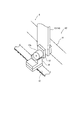
図2は上記可動子12に係合する上記係合部材16の部分拡大図を示したものであり、この図2において、上記可動子12に設けられたガイドローラや循環通路11において上記可動子12の脱落を防止する手段等は省略している。
この図に示すように、上記可動子12には略円柱状の被係合部材12aが設けられており、一方上記係合部材16は上記被係合部材12aに係合するために略半円形の凹形状を有している。
そして図1において、上記可動子12がリニアモータ制御区間A1から非リニアモータ制御区間A2に移行する際、上記係合部材16は上記ベルトコンベヤ17によって下方から上記可動子12に接近し、また上記制御手段が上記可動子12と係合部材16との位置を同期させることにより、上記係合部材16が可動子12の被係合部材12aに下方から係合するようになっている。
そして被係合部材12aが係合部材16に係合した後は、可動子12は上記ベルトコンベヤ17の駆動によって移動可能となり、各可動子12におけるベルトコンベヤ17の位置、ならびに上記非リニアモータ制御区間A2での位置は図示しないエンコーダによって上記制御手段が認識するようになっている。
その後、当該可動子12が非リニアモータ制御区間A2からリニアモータ制御区間A1に移行する際には、制御手段が上記エンコーダまたは非リニアモータ制御区間A2の下流に設けられた位置センサによって当該可動子12の位置を認識し、そして上記係合部材16が被係合部材12aより離脱すると、制御手段はリニアモータ制御区間A1の電磁石15を制御して各可動子12を個別にリニア制御することが可能となる。
FIG. 2 is a partially enlarged view of the
As shown in this figure, the
In FIG. 1, when the
After the engaged
Thereafter, when the
上記構成を有するカートン搬送装置1の動作を説明すると、まず上記カートン供給手段4がカートンマガジン2の下端部に位置する成形前のカートンCの天面C1を吸着保持し、これを底面C2および前面C3が下方を向いた状態で上記搬送面3に載置する。
このとき、上記下側吸着手段5は当該供給された成形前のカートンCの底面C2の位置に待機しており、成形前のカートンCが搬送面3に載置されると、上記底面C2を吸着保持する。
一方、上記制御手段は、成形前のカートンCが載置される位置が予め登録されており、また当該カートンCは上記循環通路11のリニアモータ制御区間A1に載置されることから、制御手段は上記カートン供給手段4が成形前のカートンCを載置する動作に同期して上記前面側保持部材13および後面側保持部材14を保持した可動子12をそれぞれその前後に移動させる。
具体的には、上記前面側保持部材13を保持した可動子12は上記搬送面3に載置される成形前のカートンCの搬送方向下流側に位置し、成形前のカートンCが搬送面3に載置されると、当該成形前のカートンCにおける天面C1と前面C3との境界(前方の境界)がその後方から当接するようになっている。
一方、上記後面側保持部材14を保持した可動子12は上記搬送面3に載置される成形前のカートンCの搬送方向上流側に位置しており、成形前のカートンCが搬送面3に載置されると、後面C4と底面C2との境界(後方の境界)にその後方から当接するようになっている。
つまり、上記カートン供給手段4が搬送面3に成形前のカートンCを供給すると、制御手段はその下流側および上流側に上記前面側保持部材13および後面側保持部材14が当接するよう、各可動子12が個別に移動するようになっている。
The operation of the carton conveying apparatus 1 having the above configuration will be described. First, the carton supply means 4 sucks and holds the top surface C1 of the carton C before molding located at the lower end portion of the carton magazine 2, and holds this on the bottom surface C2 and front surface. It is placed on the
At this time, the lower suction means 5 stands by at the position of the bottom surface C2 of the supplied carton C before molding. When the carton C before molding is placed on the
On the other hand, since the position where the carton C before molding is placed is registered in advance, and the carton C is placed in the linear motor control section A1 of the
Specifically, the
On the other hand, the
That is, when the carton supply means 4 supplies the pre-molding carton C to the
このようにして成形前のカートンCが搬送面3に載置され、上記前面側保持部材13および後面側保持部材14を保持した各可動子12がそれぞれ当該カートンCの前後に位置すると、制御手段はこれらを相対的に接近するように移動させる。
具体的には、制御手段は、前面側保持部材13を保持する可動子12よりも後面側保持部材14を保持する可動子12を相対的に速く移動させて、前面側保持部材13と後面側保持部材14とが接近するように移動させる。
すると、成形前のカートンCが前面側保持部材13と後面側保持部材14とによって上流側および下流側から押圧され、これにより上記カートンCの前面C3および後面C4が起立して成形状態となる。
この時、上記カートン供給手段4および上記下側吸着手段5は、上記成形前のカートンCが搬送面3に載置された後も所定時間上記カートンCの天面C1および底面C2を吸着した状態を維持し、上記天面C1と底面C2とを離隔させ、上記カートンCの成形を補助するようになっている。
When the carton C before molding is placed on the
Specifically, the control means moves the
Then, the carton C before molding is pressed from the upstream side and the downstream side by the front surface
At this time, the carton supply means 4 and the lower suction means 5 are in a state of adsorbing the top surface C1 and the bottom surface C2 of the carton C for a predetermined time after the pre-molding carton C is placed on the
このようにして、上記循環通路11におけるリニアモータ制御区間A1においてカートンCが成形状態となると、制御手段は前面側保持部材13および後面側保持部材14の可動子12を同じ速度で等間隔を維持したままリニアモータ制御区間A1から非リニアモータ制御区間A2へと移行させる。
具体的には、制御手段は上記ベルトコンベヤ17に設けられた係合部材16の位置を認識しており、各可動子12をそれぞれこの係合部材16に同期させて移動させ、当該可動子12の被係合部材12aに上記係合部材16を係合させ、非リニアモータ制御区間A2への移行が完了する。
このようにして可動子12が非リニアモータ制御区間A2に移行すると、その後これらの可動子12は上記ベルトコンベヤ17によって等間隔を維持したまま移動し、その結果上記前面側保持部材13および後面側保持部材14によってカートンCは成形状態を維持したまま搬送面3を搬送されることとなる。
上記成形状態とされたカートンCは、その後搬送面3の所要の位置に設定された上記フラップの閉鎖工程やカートンCに物品を収容する工程等の各作業位置において所要の作業が行われる。
そしてカートンCが搬送面3の下流端に達すると、当該カートンCを保持していた前面側保持部材13および後面側保持部材14の設けられた可動子12は、上記循環通路11に沿って搬送面3の下方へと移動し、非リニアモータ制御区間A2の下流端に可動子12が到達する。
制御手段は、ベルトコンベヤ17に設けられたエンコーダもしくは位置センサによって当該可動子12の位置を認識し、当該可動子12から係合部材16が離脱してリニアモータ制御区間A1へと移行し、新たな成形前のカートンCを成形するために搬送面3の下方に待機する。
In this way, when the carton C is in the molded state in the linear motor control section A1 in the
Specifically, the control means recognizes the position of the engaging
When the
The carton C in the molded state is then subjected to required work at each work position such as the flap closing process set at a required position on the conveying
When the carton C reaches the downstream end of the
The control means recognizes the position of the
上記実施例によれば、上記カートンCの成形および搬送を行う上記成形搬送手段6において、上記循環通路11にリニアモータ制御区間A1と非リニアモータ制御区間A2とを設定することで、非リニアモータ制御区間A2には電磁石15を設ける必要がなく、カートン搬送装置1を安価に製造することができる。
一方、上記非リニアモータ制御区間A2では、可動子12は係合部材16に係合して所定の間隔を維持して移動することから、この非リニアモータ制御区間A2においても各可動子12の位置を制御することが可能となっている。
特に本実施例におけるカートン搬送装置11では、リニアモータ制御区間A1では前面側保持部材13と後面側保持部材14との位置を個別に制御することで、カートンCを成形前の状態から成形状態とすることができ、非リニアモータ制御区間A2では所定の間隔に保持された前面側保持部材13と後面側保持部材14とによって成形後のカートンCを成形状態を維持したまま搬送することが可能となっている。
すなわち、上記カートンCの成形および搬送に前面側保持部材13と後面側保持部材14とをそのまま使用することが可能となっており、カートン搬送装置1の構成を簡易にすることが可能となる。
According to the above embodiment, the linear motor control section A1 and the non-linear motor control section A2 are set in the
On the other hand, in the non-linear motor control section A2, the
In particular, in the
That is, the front-
次に、本発明にかかる第2実施例について説明すると、図3は本発明にかかるリニア搬送装置としての物品振り分け装置101を示し、搬送される物品102を検査して不良と判定された不良物品102aについてはその進路を変更してリジェクトする装置となっている。
上記物品振り分け装置101は、物品102を搬送する正規の物品搬送コンベヤ103と、当該物品搬送コンベヤ103の側部に配置したリジェクトコンベヤ104と、上記物品搬送コンベヤ103上の物品102を上記リジェクトコンベヤ104へと進路を変更させる進路変更手段105とを備え、これらは図示しない制御手段によって制御されるようになっている。
上記正規の物品搬送コンベヤ103は、多数の物品102を一列ランダムの状態で図1の左方から右方へ搬送するようになっており、その上流側には各物品102が適正であるか否かを検査する図示しない検査装置を設けてある。
上記制御手段は上記検査装置での検査結果に基づき、物品102が正常な場合には進路変更手段105を作動させずに物品102をそのまま物品搬送コンベヤ103によって下流側に搬送させる。
一方、物品102が不良物品102aである場合には、制御手段は不良物品102aの移動に同期して進路変更手段105を作動させ、当該不良物品102aを正規の物品搬送コンベヤ103上からリジェクトコンベヤ104上へと進路を変更するようになっている。
Next, a second embodiment according to the present invention will be described. FIG. 3 shows an
The
The regular
Based on the inspection result of the inspection apparatus, the control means causes the
On the other hand, when the
上記進路変更手段105は、楕円形状の循環通路111と、該循環通路111に沿って走行する複数の可動子112と、各可動子112にリンク機構113を介して設けられたプッシャ114と、上記循環通路111に沿って設けられるとともに上記リンク機構113を構成するカムフォロワに係合してプッシャ114を作動させるカムレール115とを備えている。
上記循環通路111には、第1実施例の循環通路11と同様、電磁石116を設けたリニアモータ制御区間A1と、電磁石116を設けない非リニアモータ制御区間A2とが設定されている。
本実施例において、リニアモータ制御区間A1は図示左方の円弧状の区間から上記物品搬送コンベヤ103に隣接して設けられた直線の区間と、下流側に隣接する図示右方の円弧状の区間の一部にかけて設定されている。
一方上記非リニアモータ制御区間A2は、図示右方の区間における上記リニアモータ制御区間A1の下流端の位置から、物品搬送コンベヤ103から離隔した図示下方の直線部分にかけて設定されている。
上記非リニアモータ制御区間A2には係合部材117を備えたベルトコンベヤ118が設けられており、また上記可動子112にはそれぞれ第1実施例と同様、上記係合部材117に係合する被係合部材112aが設けられている。
このような構成により、上記可動子112の被係合部材112aに上記係合部材117が係合することで、各可動子112は上記ベルトコンベヤ118によって非リニアモータ制御区間A2を移動するようになっている。
The course changing means 105 includes an
In the
In this embodiment, the linear motor control section A1 includes a straight section provided adjacent to the
On the other hand, the non-linear motor control section A <b> 2 is set from the position of the downstream end of the linear motor control section A <b> 1 in the right section of the drawing to the straight portion in the lower part of the drawing that is separated from the
A
With such a configuration, when the engaging
上記可動子112に設けられたリンク機構113は、一端をピン121によって可動子112に揺動自在に軸支した第1アーム122を備えており、この第1アーム122の他端に上記プッシャ114を設けている。そして上記第1アーム122の中間位置に第2アーム123の一端を連結してあり、該第2アーム123の他端に上記カムレール115に係合するカムフォロワ124を設けてある。
上記カムレール115は循環通路111の上方に配置されるとともに、循環通路11の内周側もしくは外周側に沿って設けられており、内周側の部分と外周側の部分との間は滑らかに接続されている。
このような構成により、上記可動子112が移動するとカムレール115の形状に従ってカムフォロワ124が循環通路111の内周側もしくは外周側に移動し、上記第1アーム122が上記ピン121を中心に揺動するようになっている。
上記可動子112が搬送コンベヤ103に隣接した位置を移動する際、その上流側ではカムフォロワ124が循環通路111の内周側に位置しており、これにより第1アーム122は折り畳まれてプッシャ114は搬送コンベヤ103の外側に位置するようになっている。
その後可動子112が搬送コンベヤ103の下流側へと移動すると、カムフォロワ124が循環通路111の外周側へと移動し、これにより第1アーム122が揺動してプッシャ114が搬送コンベヤ103の上方を横断するように移動するようになっている。
The
The
With such a configuration, when the
When the
Thereafter, when the
上記構成を有する物品振り分け装置101によると、物品102が上記物品搬送コンベヤ103によって搬送されてくると、該物品102はセンサによって検出され、その信号は制御手段に入力される。
これと同時に、物品搬送コンベヤ103の移動量を検出するエンコーダからの信号も制御手段に入力されているので、該制御手段は上記2つの信号により物品搬送コンベヤ103によって搬送される物品102の位置を連続的に検出するようになる。
上記物品搬送コンベヤ103によって搬送される物品102は検査装置によってその良否が判定され、物品102が良品と判定された場合には進路変更手段105が作動されることはなく、良品と判定された物品102はそのまま物品搬送コンベヤ103によって下流側に搬送される。
According to the
At the same time, since a signal from an encoder for detecting the amount of movement of the
The quality of the
これに対し、検査装置によって不良物品102aと判定された物品102は物品搬送コンベヤ103によって下流側に搬送される間に、進路変更手段105のプッシャ114によってリジェクトコンベヤ104上に進路が変更されるようになっている。
上記進路変更手段105の循環通路111には、上記リニアモータ制御区間A1における上記物品搬送コンベヤ103に隣接する直線の区間の上流側の円弧状の区間に、複数の可動子112が待機している。
上記不良物品102aが検出されると、制御手段は待機していた複数の可動子112のうち、先頭の可動子112に対応する電磁石116へ電流を供給し、該可動子112を移動させる。
上記制御手段は、循環通路111の所要等間隔位置に設けた位置センサからの信号を順次入力することにより可動子112の位置を検出しながら、該可動子112を不良物品102aの移動に同期させて追従移動させる。
上記循環通路111に沿って設けられたカムレール115は、上記物品搬送コンベヤ103に隣接した直線の区間では循環通路111の内周側から外周側に向けて徐々に変化するように配置されており、このため可動子112が移動するとリンク機構113のカムフォロワ124が外周側へと移動し、上記第1アーム122が揺動してプッシャ114が作動することとなる。
上記可動子112は物品102に追従して移動することにより、上記プッシャ114は上記物品搬送コンベヤ103上の不良物品102aに係合して該不良物品102aを物品搬送コンベヤ103上からリジェクトコンベヤ104上に押し出し、その進行方向を変更させるようになっている。
On the other hand, while the
In the
When the
The control means synchronizes the
The
When the
このようにして不良物品102aをリジェクトコンベヤ104上に押出したプッシャ114は、カムレール115が再び循環通路111の外周側から内周側に移動するのに伴って上記第1アーム122が揺動することで、当該搬送コンベヤ103の上方から搬送コンベヤ103の外側へと横断するように移動する。
続いて上記可動子112は、上記循環通路111におけるリニアモータ制御区間A1から非リニアモータ制御区間A2へと移行し、その際制御手段は上記位置センサによって可動子112の位置を認識しており、また上記ベルトコンベヤ118における係合部材117の位置も認識している。
制御手段は、作動する上記ベルトコンベヤ118に同期させて、上記可動子112を作動させ、上記可動子112の被係合部材112aに上記係合部材117を係合させる。
制御手段は上記ベルトコンベヤ118を制御して非リニアモータ制御区間A2に移行した可動子112を移動させ、その後、後続の可動子112が上記非リニアモータ制御区間A2に移行するたびに、ベルトコンベヤ118を作動させて当該可動子112を非リニアモータ制御区間A2に移行させる。
そして、可動子112が非リニアモータ制御区間A2の下流端に位置し、係合部材117が可動子112から離脱すると、可動子112はリニアモータ制御区間A1へと移行して、制御手段によりこの可動子112が個別に制御可能となる。そして制御手段は上記物品搬送コンベヤ103に新たな不良物品102aが搬送されるまで、上述したように当該可動子112を待機位置へと移動させる。
The
Subsequently, the
The control means operates the
The control means controls the
When the
上記実施例によれば、上記物品102の振り分けを行う物品振り分け装置101において、上記循環通路111にリニアモータ制御区間A1と非リニアモータ制御区間A2とを設定することで、非リニアモータ制御区間A2には電磁石116を設ける必要がなく、安価に製造することができる。
一方、上記非リニアモータ制御区間A2では、可動子112は係合部材117に係合して所定の間隔を維持して移動することから、この非リニアモータ制御区間A2においても各可動子112の位置を制御することが可能となっている。
特に本実施例では、上記リニアモータ制御区間A1において可動子112を個別に作動させることで、常時全ての可動子112を循環作動させる必要がなく、不良物品102aが検出された際に当該不良物品102aに対応するプッシャ114のみを押出して不良物品102aをリジェクトコンベヤ104上に排出するようにしたので、常にアームを循環作動させるように構成した場合に比較して、騒音の低減とエネルギーの損失の低減とを図ることができる。
According to the above embodiment, in the
On the other hand, in the non-linear motor control section A2, the
In particular, in the present embodiment, by individually operating the
なお、上記2つの実施例におけるカートン搬送装置1や物品振り分け装置101は、本発明にかかるリニア搬送装置の利用例であり、リニアモータ制御区間A1において可動子をリニアモータにより個別に移動させ、非リニアモータ制御区間A2においては上記可動子を所定の間隔で搬送させるような装置として応用することが可能である。
また上記2つの実施例において、上記係合部材はベルトコンベヤ17、118によって移動するようになっているが、その他の駆動手段によって移動するような構成であってもよい。
The carton transport device 1 and the
In the above two embodiments, the engagement member is moved by the
1 カートン搬送装置 3 搬送面
6 成形搬送手段 11 循環通路
12 可動子 12a 被係合部材
13 前面側保持部材 14 後面側保持部材
15 電磁石 16 係合部材
17 ベルトコンベヤ 101 物品振り分け装置
102 物品 102a 不良物品
103 物品搬送コンベヤ 104 リジェクトコンベヤ
105 進路変更手段 111 循環通路
112 可動子 112a 被係合部材
113 リンク機構 114 プッシャ
115 カムレール 116 電磁石
117 係合部材 118 ベルトコンベヤ
124 カムフォロワ C カートン
A1 リニアモータ制御区間 A2 非リニアモータ制御区間
DESCRIPTION OF SYMBOLS 1
Claims (4)
上記循環通路における所定の区間を上記電磁石を設けたリニアモータ制御区間とし、上記リニアモータ制御区間以外の区間を電磁石を設けない非リニアモータ制御区間としたリニア搬送装置において、
上記可動子に被係合部材を設けるとともに、上記循環通路における非リニアモータ制御区間に、上記可動子の被係合部材に係合する係合部材と、当該係合部材を当該非リニアモータ制御区間に沿って移動させる駆動手段とを設け、
上記制御手段は上記リニアモータ制御区間における上記可動子の位置を認識し、上記可動子がリニアモータ制御区間から非リニアモータ制御区間に移行する際に、上記係合部材と上記可動子の被係合部材とが係合するように当該可動子または上記駆動手段の少なくともいずれか一方を制御することを特徴とするリニア搬送装置。 An endless circulation path, a mover that circulates along the circulation path, an electromagnet provided along the circulation path, and a permanent magnet provided on the mover, and controls the electromagnet to Control means for moving the mover along the circulation path,
In the linear conveyance device, the predetermined section in the circulation path is a linear motor control section provided with the electromagnet, and the non-linear motor control section is provided with a section other than the linear motor control section,
An engaging member is provided on the mover, and an engaging member that engages with the engaged member of the mover in the non-linear motor control section in the circulation passage, and the engaging member is controlled by the non-linear motor control Drive means for moving along the section,
The control means recognizes the position of the mover in the linear motor control section, and when the mover moves from the linear motor control section to the non-linear motor control section, the engagement member and the mover are engaged. A linear conveyance device that controls at least one of the movable element and the driving means so as to engage with a combined member.
上記搬送面の上流側に上記リニアモータ制御区間を設定して、制御手段は上記搬送面に供給された成形前のカートンの前後にそれぞれ可動子を位置させ、さらに上記可動子を相対的に接近させて当該成形前のカートンを上記保持部材により前後から押圧して、上記前面および後面が起立して底面および天面が相互に離隔した成形状態へと成形し、
上記搬送面における上記リニアモータ制御区間の下流側に上記非リニアモータ制御区間を設定し、上記係合部材の間隔を、上記可動子に設けられた2つの保持部材の間隔が成形状態のカートンの前面および後面に当接するような間隔となるように設定し、上記リニアモータ制御区間で成形されたカートンを当該成形状態を維持したまま搬送することを特徴とする請求項1または請求項2のいずれかに記載のリニア搬送装置。 A transport surface that supports a carton having a bottom surface facing downward, a top surface facing upward, a front surface facing front, and a rear surface facing rear, and the front and rear surfaces are inclined to the transport surface. A carton supply means for supplying a pre-molding carton having a bottom surface and a top surface that are close to each other; and a holding member that is provided on the mover and protrudes from the transport surface and contacts the front or rear of the carton;
The linear motor control section is set on the upstream side of the transport surface, and the control means positions the mover before and after the pre-molding carton supplied to the transport surface, and further moves the mover relatively close to each other. Then, the carton before molding is pressed from the front and back by the holding member, and the front surface and the rear surface stand up, and the bottom surface and the top surface are separated from each other.
The non-linear motor control section is set downstream of the linear motor control section on the transport surface, and the interval between the engagement members is set to be equal to the distance between the two holding members provided on the mover. 3. The apparatus according to claim 1, wherein the distance is set so as to be in contact with the front surface and the rear surface, and the carton molded in the linear motor control section is conveyed while maintaining the molding state. The linear conveying apparatus of crab.
上記制御手段は、上記可動子を上記物品搬送コンベヤ上の物品に追従させ、上記可動子が上記リニアモータ制御区間に位置すると、上記リンク機構によってプッシャが作動して物品搬送コンベヤ上の物品が押圧されて進路が変更されるようにしたことを特徴とする請求項1または請求項2のいずれかに記載のリニア搬送装置。 An article transport conveyor for transporting articles is provided at a position parallel to the linear motor control section in the circulation path, a pusher that operates via a link mechanism is provided on the mover, and the link mechanism is provided in the circulation path. A cam rail is provided that engages the cam follower and operates the pusher.
The control means causes the mover to follow the article on the article transport conveyor, and when the mover is positioned in the linear motor control section, the pusher is operated by the link mechanism to press the article on the article transport conveyor. The linear transport apparatus according to claim 1, wherein the course is changed.
Priority Applications (1)
| Application Number | Priority Date | Filing Date | Title |
|---|---|---|---|
| JP2013001352A JP6032418B2 (en) | 2013-01-08 | 2013-01-08 | Linear conveyor |
Applications Claiming Priority (1)
| Application Number | Priority Date | Filing Date | Title |
|---|---|---|---|
| JP2013001352A JP6032418B2 (en) | 2013-01-08 | 2013-01-08 | Linear conveyor |
Publications (2)
| Publication Number | Publication Date |
|---|---|
| JP2014133609A JP2014133609A (en) | 2014-07-24 |
| JP6032418B2 true JP6032418B2 (en) | 2016-11-30 |
Family
ID=51412210
Family Applications (1)
| Application Number | Title | Priority Date | Filing Date |
|---|---|---|---|
| JP2013001352A Active JP6032418B2 (en) | 2013-01-08 | 2013-01-08 | Linear conveyor |
Country Status (1)
| Country | Link |
|---|---|
| JP (1) | JP6032418B2 (en) |
Cited By (2)
| Publication number | Priority date | Publication date | Assignee | Title |
|---|---|---|---|---|
| US11458847B2 (en) | 2017-01-27 | 2022-10-04 | Murata Machinery, Ltd. | Article transferring device |
| NL2032479B1 (en) * | 2022-07-13 | 2024-01-25 | Royal Houdijk B V | Transport system for transporting one or more products |
Families Citing this family (13)
| Publication number | Priority date | Publication date | Assignee | Title |
|---|---|---|---|---|
| JP6615715B2 (en) * | 2016-08-08 | 2019-12-04 | 株式会社フジキカイ | Article supply equipment |
| EP3509979B1 (en) | 2016-09-09 | 2023-06-14 | The Procter & Gamble Company | System and method for independently routing vehicles and delivering containers and closures to unit operation stations |
| US10640249B2 (en) | 2016-09-09 | 2020-05-05 | The Procter & Gamble Company | Track system for creating finished products |
| CN109689510B (en) | 2016-09-09 | 2021-09-24 | 宝洁公司 | System and method for simultaneously filling containers of different shapes and/or sizes |
| CN109661623A (en) | 2016-09-09 | 2019-04-19 | 宝洁公司 | Method for producing different product simultaneously on single production line |
| US10558201B2 (en) | 2016-09-09 | 2020-02-11 | The Procter & Gamble Company | System and method for producing products based upon demand |
| EP3510459A2 (en) | 2016-09-09 | 2019-07-17 | The Procter and Gamble Company | System and method for independently routing container-loaded vehicles to create different finished products |
| CN109661352B (en) | 2016-09-09 | 2021-12-03 | 宝洁公司 | System and method for simultaneously filling containers with different fluid compositions |
| JP6803785B2 (en) * | 2017-03-29 | 2020-12-23 | 三菱重工機械システム株式会社 | Transport system |
| BR112021023067A2 (en) * | 2019-05-17 | 2022-01-25 | Westrock Packaging Systems Llc | Flexible pitch product measuring system |
| JP7307329B2 (en) | 2019-08-20 | 2023-07-12 | 澁谷工業株式会社 | Carrier transfer device |
| DE102021107189A1 (en) * | 2021-03-23 | 2022-09-29 | Taktomat Kurvengesteuerte Antriebssysteme Gmbh | transport system |
| CN117228254B (en) * | 2023-11-10 | 2024-04-05 | 昆山纳博旺精工科技有限公司 | Mixed splicing type flexible transmission system |
Family Cites Families (3)
| Publication number | Priority date | Publication date | Assignee | Title |
|---|---|---|---|---|
| JPH02209315A (en) * | 1989-02-07 | 1990-08-20 | Mitsubishi Heavy Ind Ltd | Bottle inspecting device |
| JPH11277643A (en) * | 1998-03-27 | 1999-10-12 | O M Ltd | Method for unloading/molding carton and device therefor |
| DE20002411U1 (en) * | 2000-02-10 | 2001-06-13 | Horst Michael | Device for deflecting objects, in particular containers, from a movement path |
-
2013
- 2013-01-08 JP JP2013001352A patent/JP6032418B2/en active Active
Cited By (2)
| Publication number | Priority date | Publication date | Assignee | Title |
|---|---|---|---|---|
| US11458847B2 (en) | 2017-01-27 | 2022-10-04 | Murata Machinery, Ltd. | Article transferring device |
| NL2032479B1 (en) * | 2022-07-13 | 2024-01-25 | Royal Houdijk B V | Transport system for transporting one or more products |
Also Published As
| Publication number | Publication date |
|---|---|
| JP2014133609A (en) | 2014-07-24 |
Similar Documents
| Publication | Publication Date | Title |
|---|---|---|
| JP6032418B2 (en) | Linear conveyor | |
| US10668506B2 (en) | Sorting conveyor with article removal device | |
| JP6060673B2 (en) | Article distribution device | |
| JP6615715B2 (en) | Article supply equipment | |
| CN105683066A (en) | Conveying device for conveying workpieces, in particular circuit boards, in the conveying direction along a conveying line. | |
| JP6402855B2 (en) | Article transfer system | |
| JP2016137968A (en) | Conveying device | |
| JP2011105396A (en) | Article conveying device | |
| US7536842B2 (en) | Machine and a method for filling box-like containers with articles arranged side by side and vertically | |
| JP6628500B2 (en) | Box packing device and box packing method | |
| JP6411796B2 (en) | Sorting device | |
| JP4945085B2 (en) | Container alignment apparatus and container alignment method | |
| US20190233221A1 (en) | Transfer of objects | |
| JP2016520495A (en) | manipulator | |
| JP6380451B2 (en) | Conveyor device and automatic warehouse | |
| JP2012246079A (en) | Article carrying device | |
| JP6286159B2 (en) | Alignment method and apparatus | |
| JP2011016660A (en) | Line increasing device | |
| JP4984833B2 (en) | Transport equipment | |
| JP6094734B2 (en) | Carton molding equipment | |
| JP6168298B2 (en) | Article delivery device | |
| JP2016055875A (en) | Carton assembling conveying device | |
| JP6397682B2 (en) | Article transfer apparatus and article transfer method | |
| JP6260152B2 (en) | Article conveying device | |
| JP6889827B2 (en) | Aligner and how to align articles |
Legal Events
| Date | Code | Title | Description |
|---|---|---|---|
| A621 | Written request for application examination |
Free format text: JAPANESE INTERMEDIATE CODE: A621 Effective date: 20151228 |
|
| A977 | Report on retrieval |
Free format text: JAPANESE INTERMEDIATE CODE: A971007 Effective date: 20160914 |
|
| TRDD | Decision of grant or rejection written | ||
| A01 | Written decision to grant a patent or to grant a registration (utility model) |
Free format text: JAPANESE INTERMEDIATE CODE: A01 Effective date: 20160928 |
|
| A61 | First payment of annual fees (during grant procedure) |
Free format text: JAPANESE INTERMEDIATE CODE: A61 Effective date: 20161011 |
|
| R150 | Certificate of patent or registration of utility model |
Ref document number: 6032418 Country of ref document: JP Free format text: JAPANESE INTERMEDIATE CODE: R150 |