JP6889827B2 - Aligner and how to align articles - Google Patents
Aligner and how to align articles Download PDFInfo
- Publication number
- JP6889827B2 JP6889827B2 JP2017126016A JP2017126016A JP6889827B2 JP 6889827 B2 JP6889827 B2 JP 6889827B2 JP 2017126016 A JP2017126016 A JP 2017126016A JP 2017126016 A JP2017126016 A JP 2017126016A JP 6889827 B2 JP6889827 B2 JP 6889827B2
- Authority
- JP
- Japan
- Prior art keywords
- conveyor
- articles
- turntable
- guide
- article
- Prior art date
- Legal status (The legal status is an assumption and is not a legal conclusion. Google has not performed a legal analysis and makes no representation as to the accuracy of the status listed.)
- Active
Links
Images


Landscapes
- Feeding Of Articles To Conveyors (AREA)
- Attitude Control For Articles On Conveyors (AREA)
Description
本発明は、容器等の物品を検査や梱包のためにコンベアにより搬送し、作業台に整列させる整列機、及び物品の整列方法に関する。 The present invention relates to an aligner for transporting articles such as containers by a conveyor for inspection and packing and aligning them on a work table, and a method for aligning articles.
従来から、容器等の物品について、コンベアで物品を搬送し作業台に整列させて、人の手やカメラにより物品の最終チェックを行う、整列機が使用されている。 Conventionally, an aligner has been used in which articles such as containers are transported by a conveyor and aligned on a work table, and the final check of the articles is performed by a human hand or a camera.
この種の整列機においては、設置スペースを小さくするためにレイアウトの工夫が必要になることがあり、このような場合、レイアウト上の自由度を高めるために、例えばコンベアの流れる方向から別方向に物品を方向転換させるための方向転換装置を組み込むことが行われている。 In this type of aligner, it may be necessary to devise a layout in order to reduce the installation space. In such a case, in order to increase the degree of freedom in layout, for example, in a different direction from the direction in which the conveyor flows. It is practiced to incorporate a redirection device for reorienting the article.
方向転換装置としては、コンベアで搬送される物品を、ストッパによって一時的に区切り、区切った物品を押出部材で物品を押し出すことで方向転換させる技術が存在する(例えば、特許文献1を参照)。 As a direction changing device, there is a technique in which an article conveyed by a conveyor is temporarily separated by a stopper, and the separated article is extruded by an extrusion member to change the direction (see, for example, Patent Document 1).
また、別の技術として、物品の流れる直線コンベアに、カーブ状のコンベアを繋げ、物品の流れ方向を補助するガイドを設けて方向転換させる技術も存在する(例えば、特許文献2を参照)。 Further, as another technique, there is also a technique of connecting a curved conveyor to a linear conveyor through which articles flow and providing a guide for assisting the flow direction of articles to change the direction (see, for example, Patent Document 2).
さらには、ターンテーブルで方向の異なるコンベアを繋げる公知技術が存在する(例えば、特許文献3を参照)。 Further, there is a known technique for connecting conveyors having different directions with a turntable (see, for example, Patent Document 3).
しかしながら、特許文献1に記載される容器整列装置は、コンベアを平行に配置し、コンベアと直交方向に押し出すことで複数列に整列するものであり、コンベアの搬送方向は所定の方向に制約されている。したがって、コンベアの搬送方向に自由度がなく、レイアウト変更に対応することは難しい。
However, the container aligning device described in
また、特許文献2に記載される方向転換ガイドを用いた搬送装置では、使用するカーブ状コンベアが技術的に大型にならざるを得ず、設置面積を大きく取る必要が有る他、駆動機構が複雑なものとなるという欠点もある。
Further, in the transfer device using the direction change guide described in
特許文献3に記載される搬送方向変換装置は、コンベアからコンベアへと搬送するものであり、コンベアから作業台へと搬送し、容器を整列させることは考慮されていない。また、特許文献3記載の搬送方向変換装置は、容器等の物品をラックに入れて搬送することが前提であり、例えば一定間隔で並ぶ容器のような細長の物品を個別に搬送しようとすると、コンベアとターンテーブルの速度の設定によっては、ターンテーブルからコンベア、コンベアからターンテーブルへの乗り移り時に、乗り移り先のターンテーブルやコンベアに引きずられて物品が転倒する恐れがある。
The transport direction changing device described in
本発明の目的は、レイアウトの自由度が高く、コンパクト且つ安定して整列機の作業台まで物品を搬送することができ、しかも、コンベアから搬送される物品について、物品に傷を付けることが無く整列させることが可能な整列機を提供すること、さらには物品の整列方法を提供することである。 An object of the present invention is that the degree of freedom in layout is high, the article can be compactly and stably transported to the workbench of the aligner, and the article transported from the conveyor is not damaged. It is to provide an aligner capable of aligning, and further to provide a method of aligning articles.
前述の目的を達成するために、本発明の整列機は、物品を作業台まで搬送して整列させる整列機であって、前記整列機は少なくとも、物品を搬送するコンベアと、コンベアから作業台まで物品の流れを誘導し方向転換をさせるための方向転換装置とで構成され、前記方向転換装置は、ターンテーブルを備え、前記作業台にはせり上がり可能な壁が設けられ、当該壁がせり上がることで前記ターンテーブル上の物品が整列して搬送される区画領域が形成され、前記ターンテーブル上の物品の搬送速度が、前記コンベア上の物品の搬送速度よりも遅く設定されていることを特徴とする。あるいは、物品を作業台まで搬送して整列させる整列機であって、前記整列機は少なくとも、物品を搬送するコンベアと、コンベアから作業台まで物品の流れを誘導し方向転換をさせるための方向転換装置とで構成され、前記方向転換装置は、ターンテーブルを備え、コンベアからターンテーブルの上へ搬送される物品を誘導するためのガイドが設けられており、前記ガイドが、直線状の第1のガイドと第2のガイドとから構成され、第1のガイドはコンベアにおける物品の搬送方向に対して斜めに設置され、第2のガイドによりターンテーブル上の物品の作業台への押し出し方向が規制され、第2のガイドは前記ターンテーブルより作業台側に突出しておらず、前記ターンテーブル上の物品の搬送速度が、前記コンベア上の物品の搬送速度よりも遅く設定されていることを特徴とする In order to achieve the above-mentioned object, the aligner of the present invention is an aligner for transporting and aligning articles to a work table, and the aligner is at least a conveyor for transporting articles and a conveyor to a work table. It is composed of a direction changing device for guiding the flow of goods and changing the direction. The direction changing device is provided with a turntable, and the workbench is provided with a wall that can be lifted, and the wall is raised. As a result, a compartment area in which the articles on the turntable are aligned and transported is formed, and the transport speed of the articles on the turntable is set to be slower than the transport speed of the articles on the conveyor. And. Alternatively, it is an aligner that transports and aligns articles to a work table, and the aligner is at least a conveyor that conveys articles and a direction change for guiding the flow of articles from the conveyor to the work table and changing the direction. The turning device is composed of a device, the direction changing device is provided with a turntable, and a guide for guiding an article to be conveyed from the conveyor onto the turntable is provided, and the guide is a linear first first. It is composed of a guide and a second guide. The first guide is installed at an angle to the transport direction of the article on the conveyor, and the second guide regulates the pushing direction of the article on the turntable to the work table. The second guide does not project toward the work table from the turntable, and the transport speed of the articles on the turntable is set to be slower than the transport speed of the articles on the conveyor.
また、本発明の物品の整列方法は、物品を搬送するコンベアと、コンベアから作業台まで物品の流れを誘導し方向転換をさせるための方向転換装置とで構成され、前記方向転換装置がターンテーブルを備える整列機により物品を整列させる物品の整列方法において、物品をコンベアで搬送する段階と、コンベアの進路上に設置されたガイドにより物品がターンテーブルまで誘導される段階と、ターンテーブル上の物品が作業台に乗り移る段階を経ることで物品が作業台まで搬送される段階とを有し、前記作業台にせり上がり可能な壁を設け、当該壁がせり上がることで形成される区画領域に前記ターンテーブル上の物品を整列させて搬送し、前記ターンテーブル上の物品の搬送速度が、前記コンベア上の物品の搬送速度よりも遅くなるように設定することを特徴とする。あるいは、物品を搬送するコンベアと、コンベアから作業台まで物品の流れを誘導し方向転換をさせるための方向転換装置とで構成され、前記方向転換装置がターンテーブルを備える整列機により物品を整列させる物品の整列方法において、物品をコンベアで搬送する段階と、コンベアの進路上に設置されたガイドにより物品がターンテーブルまで誘導される段階と、ターンテーブル上の物品が作業台に乗り移る段階を経ることで物品が作業台まで搬送される段階とを有し、コンベアからターンテーブルの上へ搬送される物品を誘導するためのガイドを設け、前記ガイドが、直線状の第1のガイドと第2のガイドとから構成され、第1のガイドはコンベアにおける物品の搬送方向に対して斜めに設置され、第2のガイドによりターンテーブル上の物品の作業台への押し出し方向が規制され、第2のガイドは前記ターンテーブルより作業台側に突出しておらず、前記ターンテーブル上の物品の搬送速度が、前記コンベア上の物品の搬送速度よりも遅くなるように設定することを特徴とする。 Further, the method of aligning articles of the present invention includes a conveyor for transporting articles and a direction changing device for guiding the flow of articles from the conveyor to a work table to change the direction, and the direction changing device is a turntable. In the method of aligning articles by an aligning machine equipped with, an article is conveyed by a conveyor, an article is guided to a turntable by a guide installed on the path of the conveyor, and an article on the turntable. The workbench has a stage in which articles are transported to the workbench by passing through a stage in which the workbench is transferred to the workbench, and a wall that can be raised is provided on the workbench. The article is aligned and transported on the turntable, and the transport speed of the article on the turntable is set to be slower than the transport speed of the article on the conveyor. Alternatively, it is composed of a conveyor for transporting articles and a direction changing device for guiding the flow of articles from the conveyor to the work table to change the direction, and the direction changing device aligns the articles by an aligner provided with a turntable. In the method of arranging articles, the steps of transporting the articles by a conveyor, guiding the articles to the turntable by a guide installed on the path of the conveyor, and transferring the articles on the turntable to the work table are performed. It has a stage in which the article is conveyed to the work table, and a guide for guiding the article to be conveyed from the conveyor onto the turntable is provided, and the guides are a linear first guide and a second guide. Composed of a guide, the first guide is installed at an angle to the transport direction of the article on the conveyor, the second guide regulates the pushing direction of the article on the turntable to the work table, and the second guide. Is not protruding from the turntable toward the workbench, and the transport speed of the articles on the turntable is set to be slower than the transport speed of the articles on the conveyor.
本発明においては、整列機の方向転換装置にターンテーブルを使用していることから、例えばガイドの角度を変更すること等により、搬送方向を任意の方向に容易に変更することが可能であり、レイアウト上の自由度が高い。また、ターンテーブル上の物品の搬送速度をコンベア上の物品の搬送速度よりも遅く設定することにより、コンベアとターンテーブル間および、ターンテーブルから作業台への物品の乗り移り時の転倒が防止され、物品の搬送及び整列がスムーズなものとなる。 In the present invention, since the turntable is used as the direction changing device of the aligner, the transport direction can be easily changed to an arbitrary direction by, for example, changing the angle of the guide. High degree of freedom in layout. Further, by setting the transport speed of the article on the turntable to be slower than the transport speed of the article on the conveyor, it is possible to prevent the article from tipping over between the conveyor and the turntable and when the article is transferred from the turntable to the work table. Goods can be transported and aligned smoothly.
コンベアから作業台へと物品を移送し配列する場合、コンベアから一定の間隔で搬送されてくる物品を、互いに接するように間隔を詰めて配列する必要がある。前記ターンテーブルは、方向転換の機能を有するのみならず、物品の搬送間隔を調整する機能も有し、ターンテーブル上の物品の搬送速度をコンベア上の物品の搬送速度よりも遅く設定することで、一定の間隔を開けて搬送されてくる物品が、速度調整されて互いに接するように間隔を詰めて作業台へと搬送される。これにより、搬送から整列までの一連の作業が円滑に行われる。 When transferring and arranging articles from a conveyor to a workbench, it is necessary to arrange the articles transported from the conveyor at regular intervals so that they are in contact with each other. The turntable not only has a function of changing direction, but also has a function of adjusting the transport interval of articles, and by setting the transport speed of articles on the turntable to be slower than the transport speed of articles on the conveyor. , The articles transported at regular intervals are speed-adjusted and transported to the workbench at close intervals so as to come into contact with each other. As a result, a series of operations from transportation to alignment can be smoothly performed.
本発明の整列機によれば、レイアウトの自由度が高く、コンパクト且つ安定して整列機の作業台まで物品を搬送することができ、しかも、コンベアから搬送される物品について、物品に傷を付けることが無く整列させることが可能である。 According to the aligner of the present invention, the degree of freedom in layout is high, the article can be compactly and stably transported to the work table of the aligner, and the article transported from the conveyor is damaged. It is possible to align without any problems.
以下、本発明の実施形態について、図面を参照しながら詳細に説明する。 Hereinafter, embodiments of the present invention will be described in detail with reference to the drawings.
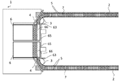
図1は、整列機1の全体図である。当該整列機1において、作業台6まで搬送される物品は、飲料等液体を収容するために用いられる容器7である。上記容器7は、例えばブロー成形や射出成形により成形された樹脂製のボトルである。係るボトルは内部が空洞であり、底部及び胴部の断面が略円形状になっている。
FIG. 1 is an overall view of the
整列機1は、容器7を搬送するコンベア2と、容器の流れ方向を転換させるターンテーブル3と、作業台6で構成されており、コンベア2及びターンテーブル3上の容器7の落下を防止するためのレール5と、ターンテーブル3に容器7を誘導させるためのガイド4が設けられている。
The aligning
容器7は、成形機(図示せず)によって成形され、後加工機(図示せず)によってバリ処理等の後加工を経て、容器同士が一定間隔を保った状態でコンベア2に載せられる。この時、成形機では間欠的に成形が行われることから、成形された容器7は、一定の間隔で供給され、その結果、所定の間隔を開けてコンベア2上に次々と載せられることになる。
The
コンベア2上に容器7を所定の間隔をもって配列することは、メンテナンス上も有利であり、例えば成形機でトラブルが発生した場合にも対応が容易である。コンベア2上で容器7が密集していると、トラブルが発生した場合に余裕がなく、トラブルに対処することが難しい。
Arranging the
前記容器7は、コンベア2によりガイド4まで搬送されると、ガイド4に接触したまま沿うようにしてターンテーブル3まで誘導される。
When the
ターンテーブル3に誘導された容器7は、ここで方向転換され、コンベア2による搬送方向に対して直交する方向に搬送される。なお、ターンテーブル3においては、設置されるガイドを取り替えるか、ガイドの角度を変更することにより、容器7の搬送方向を任意に変更することが可能である。
The
このとき、ガイド4に接触した容器7は、ターンテーブル3に乗り移るが、ターンテーブル3上の容器7は、コンベア2上の容器7よりも搬送速度が低速になるように設定されているので、コンベア2上で一定の間隔で搬送されてきた容器7は、ターンテーブル3上でその配列間隔が狭まり、隣接する容器7同士が互いに接する状態で作業台6へと搬送される。ターンテーブル3は、方向転換機能と間隔調整機能とを有し、コンベア2により所定の間隔で搬送されてきた容器7は、隙間無く整列に適した状態で作業台6へと移送される。
At this time, the
また、ターンテーブル3の搬送速度をコンベア2の搬送速度よりも遅く設定することは、容器7の転倒を防止する上でも有効である。すなわち、ターンテーブル3上の容器7はコンベア2上の容器7よりも低速であるため、図2に示すように、容器同士の間隔が狭まり、ほぼ密着した状態でターンテーブル3上を搬送される。ターンテーブル3から作業台6に乗り移る時、ターンテーブル3上の容器7が後続の容器に押し出されるようにして作業台6に乗り移るが、ターンテーブル3上の容器7の搬送速度がコンベア2上の搬送速度よりも低速であるため、容器間の間隔が狭まり、容器同士で支えられた状態になるので、容器7が転倒することはない。
Further, setting the transport speed of the
ここで、ターンテーブル3上の容器7の搬送速度は、前述の機能を考慮して決定すればよいが、例えば0.01〜0.9m/sの範囲内が望ましい。搬送速度が0.9m/s以上であると、ターンテーブル上の容器7が暴れてレール5等に衝突して傷がつく可能性がある。一方、コンベア2上の容器7の搬送速度は、ターンテーブル上の容器7の搬送速度よりも速いことを前提として、0.1〜1.2m/sの範囲内であることが望ましい。搬送速度が1.2m/sより速いと、コンベア2上の容器7が暴れてレール5等に衝突して傷がつく可能性がある。なお、ターンテーブル3は、物品が経路に詰まることを防止するため、モーター等の動力によって定常回転していることが望ましい。
Here, the transport speed of the
また、ターンテーブル3において、搬送される容器7の搬送方向を規制するためのガイド4は、直線状であることが望ましい。ガイド4が直線状であることで、曲線状である場合よりもコンベア2からターンテーブル3までの距離が縮まり、コンベア2からターンテーブル3への容器の乗り移りが迅速に行われるようになる。
Further, in the
なお、ターンテーブル3と作業台6の間には、搬送補助装置(図示せず)を設置することが望ましい。搬送補助装置は例えばエアノズルであり、容器7をエアー圧により作業台6へと押し出すことで、容器7をターンテーブル3から作業台6へよりスムーズに乗り移らせることが可能になる。
It is desirable to install a transport assisting device (not shown) between the
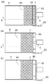
容器7は、ターンテーブル3から順次作業台6に乗り移り、搬送方向を約90度変えながら、図3A及び図4Aに示すように、作業台の区画領域62に一列に並ぶ。一列に並んだ容器7が一定数に達したことをセンサー(図示せず)が感知すると、シャッター63が作動して、作業台6とターンテーブル3間の容器7の搬送を一時的に遮断する。シャッター63が作動した後、図3B及び図4Bのように壁66が下がり、作業台6と作業台の区画領域62が連通する。
The
その後押出装置65が作動し、区画領域62に並んだ容器7は、押出装置65によって作業台6の中央側の領域64に押しやられる。そして図3Cに示すように、押出装置65が戻ると同時に、壁66がせり上がり、シャッター63が初期位置に戻るので、再び作業台の区画領域62に容器7が順次供給されるようになる。
After that, the
このように、本実施形態では、ターンテーブル3上の物品の搬送速度をコンベア2上の物品の搬送速度よりも遅くすることで、コンベア2とターンテーブル3間、及びターンテーブル3と作業台6への容器7の乗り移り時の容器7の転倒を防ぎ、容器7の作業台6までの搬送をスムーズにする効果がある。
As described above, in the present embodiment, by making the transport speed of the articles on the
次に、本発明の変形例について図5及び図6を参照して説明する。図5において、ガイド4が、コンベア側に位置するガイド41と、作業台側に位置する42の2つに分かれており、コンベア側に位置するガイド41が少なくとも可動になっている。
Next, a modification of the present invention will be described with reference to FIGS. 5 and 6. In FIG. 5, the
前記コンベア側に位置するガイド41を動作させると図6に示すようになり、コンベア2の終端21が解放され、コンベア2で搬送されている不良品72がターンテーブル3まで誘導されずにコンベア2の終端21に到達するようになる。
When the
このようにすることで、成形機のオペレーションの設定ミスや、後加工ラインの不調等により、ボトルの形状や色が製品の要求される品質に届いていない不良品72が搬送されてきた場合であっても、人の手で不良品を取り除くためにコンベア2やターンテーブル3を一時停止する必要がなくなり、作業効率の低下を防止できる。
By doing so, when a
すなわち、不良品72の発生時に前記コンベア2側に位置するガイド41を動かすことで、ターンテーブル3上にある良品71についてはそのまま作業台6へ誘導され、その後に搬送されてくる不良品72はコンベア2の終端21まで誘導され、不良品72を選り分けることが可能になる。
That is, by moving the
コンベア2の終端21には、収容箱8を設置することが望ましい。こうすることで、コンベア2の終端21を乗り越えた不良品72が落下した時に、自動的に収容箱8に収容される。
It is desirable to install a
以上、本発明の実施形態について説明したが、本発明の趣旨に逸脱しない範囲内で前記実施形態における構成要素を周知の構成要素に置き換えることが可能であり、前記実施形態に限定されるものではない。 Although the embodiments of the present invention have been described above, the components in the embodiment can be replaced with well-known components within a range that does not deviate from the gist of the present invention, and the components are not limited to the above-described embodiments. Absent.
例えば、本実施形態ではターンテーブルにより容器の搬送方向を約90度変えたが、90度に限らず、0〜180度の範囲内で任意に搬送方向を変えることが可能である。 For example, in the present embodiment, the transport direction of the container is changed by about 90 degrees by the turntable, but the transport direction is not limited to 90 degrees and can be arbitrarily changed within the range of 0 to 180 degrees.
1 整列機
2 コンベア
21 コンベアの終端
3 ターンテーブル
4 ガイド
41 コンベア側に位置するガイド
42 作業台側に位置するガイド
5 レール
6 作業台
62 作業台の区画領域
63 シャッター
64 作業台の中央側の領域
65 押出装置
66 壁
7 容器
71 容器の良品
72 容器の不良品
8 収容箱
1
Claims (9)
前記整列機は少なくとも、物品を搬送するコンベアと、コンベアから作業台まで物品の流れを誘導し方向転換をさせるための方向転換装置とで構成され、
前記方向転換装置は、ターンテーブルを備え、
前記作業台にはせり上がり可能な壁が設けられ、当該壁がせり上がることで前記ターンテーブル上の物品が整列して搬送される区画領域が形成され、
前記ターンテーブル上の物品の搬送速度が、前記コンベア上の物品の搬送速度よりも遅く設定されていることを特徴とする物品の整列機。 An aligner that transports and aligns articles to a workbench.
The aligner is composed of at least a conveyor for transporting articles and a direction changing device for guiding the flow of articles from the conveyor to the workbench to change the direction.
The turning device includes a turntable and
The workbench is provided with a wall that can be lifted up, and the wall is raised to form a compartment area in which articles on the turntable are aligned and transported.
An article aligner characterized in that the transport speed of articles on the turntable is set to be slower than the transport speed of articles on the conveyor.
前記整列機は少なくとも、物品を搬送するコンベアと、コンベアから作業台まで物品の流れを誘導し方向転換をさせるための方向転換装置とで構成され、The aligner is composed of at least a conveyor for transporting articles and a direction changing device for guiding the flow of articles from the conveyor to the workbench to change the direction.
前記方向転換装置は、ターンテーブルを備え、The turning device includes a turntable and
コンベアからターンテーブルの上へ搬送される物品を誘導するためのガイドが設けられており、There is a guide to guide the goods to be transported from the conveyor onto the turntable.
前記ガイドが、直線状の第1のガイドと第2のガイドとから構成され、第1のガイドはコンベアにおける物品の搬送方向に対して斜めに設置され、第2のガイドによりターンテーブル上の物品の作業台への押し出し方向が規制され、第2のガイドは前記ターンテーブルより作業台側に突出しておらず、The guide is composed of a linear first guide and a second guide, the first guide is installed obliquely with respect to the transport direction of the article on the conveyor, and the article on the turntable is provided by the second guide. The direction of pushing out to the workbench is restricted, and the second guide does not protrude toward the workbench from the turntable.
前記ターンテーブル上の物品の搬送速度が、前記コンベア上の物品の搬送速度よりも遅く設定されていることを特徴とする物品の整列機。An article aligner characterized in that the transport speed of articles on the turntable is set to be slower than the transport speed of articles on the conveyor.
物品をコンベアで搬送する段階と、
コンベアの進路上に設置されたガイドにより物品がターンテーブルまで誘導される段階と、
ターンテーブル上の物品が作業台に乗り移る段階を経ることで物品が作業台まで搬送される段階とを有し、
前記作業台にせり上がり可能な壁を設け、当該壁がせり上がることで形成される区画領域に前記ターンテーブル上の物品を整列させて搬送し、
前記ターンテーブル上の物品の搬送速度が、前記コンベア上の物品の搬送速度よりも遅くなるように設定することを特徴とする物品の整列方法。 The article is composed of a conveyor for transporting articles and a direction changing device for guiding the flow of articles from the conveyor to the workbench to change the direction, and the direction changing device aligns the articles by an aligner equipped with a turntable. In the alignment method
The stage of transporting goods on a conveyor and
At the stage where the goods are guided to the turntable by the guide installed on the course of the conveyor,
It has a stage where the article is transported to the work table by passing through the stage where the article on the turntable is transferred to the work table.
A wall that can be lifted up is provided on the work table, and articles on the turntable are aligned and transported in a compartment area formed by the wall rising up.
A method for arranging articles, which comprises setting the transport speed of articles on the turntable to be slower than the transport speed of articles on the conveyor.
物品をコンベアで搬送する段階と、The stage of transporting goods on a conveyor and
コンベアの進路上に設置されたガイドにより物品がターンテーブルまで誘導される段階と、At the stage where the goods are guided to the turntable by the guide installed on the course of the conveyor,
ターンテーブル上の物品が作業台に乗り移る段階を経ることで物品が作業台まで搬送される段階とを有し、It has a stage where the article is transported to the work table by passing through the stage where the article on the turntable is transferred to the work table.
コンベアからターンテーブルの上へ搬送される物品を誘導するためのガイドを設け、A guide is provided to guide the goods to be transported from the conveyor onto the turntable.
前記ガイドが、直線状の第1のガイドと第2のガイドとから構成され、第1のガイドはコンベアにおける物品の搬送方向に対して斜めに設置され、第2のガイドによりターンテーブル上の物品の作業台への押し出し方向が規制され、第2のガイドは前記ターンテーブルより作業台側に突出しておらず、The guide is composed of a linear first guide and a second guide, the first guide is installed obliquely with respect to the transport direction of the article on the conveyor, and the article on the turntable is provided by the second guide. The direction of pushing out to the workbench is restricted, and the second guide does not protrude toward the workbench from the turntable.
前記ターンテーブル上の物品の搬送速度が、前記コンベア上の物品の搬送速度よりも遅くなるように設定することを特徴とする物品の整列方法。A method for arranging articles, which comprises setting the transport speed of articles on the turntable to be slower than the transport speed of articles on the conveyor.
Priority Applications (1)
| Application Number | Priority Date | Filing Date | Title |
|---|---|---|---|
| JP2017126016A JP6889827B2 (en) | 2017-06-28 | 2017-06-28 | Aligner and how to align articles |
Applications Claiming Priority (1)
| Application Number | Priority Date | Filing Date | Title |
|---|---|---|---|
| JP2017126016A JP6889827B2 (en) | 2017-06-28 | 2017-06-28 | Aligner and how to align articles |
Publications (2)
| Publication Number | Publication Date |
|---|---|
| JP2019006593A JP2019006593A (en) | 2019-01-17 |
| JP6889827B2 true JP6889827B2 (en) | 2021-06-18 |
Family
ID=65028388
Family Applications (1)
| Application Number | Title | Priority Date | Filing Date |
|---|---|---|---|
| JP2017126016A Active JP6889827B2 (en) | 2017-06-28 | 2017-06-28 | Aligner and how to align articles |
Country Status (1)
| Country | Link |
|---|---|
| JP (1) | JP6889827B2 (en) |
-
2017
- 2017-06-28 JP JP2017126016A patent/JP6889827B2/en active Active
Also Published As
| Publication number | Publication date |
|---|---|
| JP2019006593A (en) | 2019-01-17 |
Similar Documents
| Publication | Publication Date | Title |
|---|---|---|
| JP6032418B2 (en) | Linear conveyor | |
| US12043533B2 (en) | Filling system for liquid products and method for filling liquid products into bottles | |
| JP6916237B2 (en) | Sorting conveyor with article removal device | |
| EP2001774B1 (en) | Transporting system for bottles or similar containers, and installation for handling bottles or similar containers | |
| US9290321B2 (en) | Storage section of a conveyor device and method for temporarily storing articles | |
| CN107878819B (en) | item distribution system | |
| JP2006321567A (en) | Continuously operating packaging device | |
| JP6402855B2 (en) | Article transfer system | |
| AU2002337898A1 (en) | Product conveying and accumulation system and method | |
| JPS58193824A (en) | Selector for single article | |
| EP1461275B1 (en) | Product conveying and accumulation system and method | |
| JP7114419B2 (en) | cartoning system | |
| US20160075459A1 (en) | Method and device for handling elongated articles | |
| US9994397B2 (en) | Device and method for portioning a flow of individual products | |
| JP6889827B2 (en) | Aligner and how to align articles | |
| JP4960267B2 (en) | Article supply equipment | |
| JP6308887B2 (en) | Accumulator | |
| JP2013163552A (en) | Food material feeder | |
| JP6411796B2 (en) | Sorting device | |
| JP3932620B2 (en) | Preform transport method and preform mounting member used in this transport method | |
| JP6475144B2 (en) | Boxing equipment | |
| JP6928246B2 (en) | Packing equipment | |
| JP2014024623A (en) | Work categorization apparatus | |
| JP4543827B2 (en) | Air conveyor | |
| JPH0970828A (en) | Preform cooling and transporting apparatus |
Legal Events
| Date | Code | Title | Description |
|---|---|---|---|
| A621 | Written request for application examination |
Free format text: JAPANESE INTERMEDIATE CODE: A621 Effective date: 20200228 |
|
| A977 | Report on retrieval |
Free format text: JAPANESE INTERMEDIATE CODE: A971007 Effective date: 20210120 |
|
| A131 | Notification of reasons for refusal |
Free format text: JAPANESE INTERMEDIATE CODE: A131 Effective date: 20210127 |
|
| A521 | Request for written amendment filed |
Free format text: JAPANESE INTERMEDIATE CODE: A523 Effective date: 20210329 |
|
| TRDD | Decision of grant or rejection written | ||
| A01 | Written decision to grant a patent or to grant a registration (utility model) |
Free format text: JAPANESE INTERMEDIATE CODE: A01 Effective date: 20210421 |
|
| A61 | First payment of annual fees (during grant procedure) |
Free format text: JAPANESE INTERMEDIATE CODE: A61 Effective date: 20210504 |
|
| R150 | Certificate of patent or registration of utility model |
Ref document number: 6889827 Country of ref document: JP Free format text: JAPANESE INTERMEDIATE CODE: R150 |
|
| R250 | Receipt of annual fees |
Free format text: JAPANESE INTERMEDIATE CODE: R250 |
|
| R250 | Receipt of annual fees |
Free format text: JAPANESE INTERMEDIATE CODE: R250 |