EP0486440A1 - Vorrichtung zum Ausgeben von flüssigen Produkten zu drehbeweglichen Teilen, insbesondere für Getränkeabfüller - Google Patents
Vorrichtung zum Ausgeben von flüssigen Produkten zu drehbeweglichen Teilen, insbesondere für Getränkeabfüller Download PDFInfo
- Publication number
- EP0486440A1 EP0486440A1 EP91830492A EP91830492A EP0486440A1 EP 0486440 A1 EP0486440 A1 EP 0486440A1 EP 91830492 A EP91830492 A EP 91830492A EP 91830492 A EP91830492 A EP 91830492A EP 0486440 A1 EP0486440 A1 EP 0486440A1
- Authority
- EP
- European Patent Office
- Prior art keywords
- carousel
- platform
- ducts
- chamber
- liquid
- Prior art date
- Legal status (The legal status is an assumption and is not a legal conclusion. Google has not performed a legal analysis and makes no representation as to the accuracy of the status listed.)
- Granted
Links
Images
Classifications
-
- B—PERFORMING OPERATIONS; TRANSPORTING
- B65—CONVEYING; PACKING; STORING; HANDLING THIN OR FILAMENTARY MATERIAL
- B65B—MACHINES, APPARATUS OR DEVICES FOR, OR METHODS OF, PACKAGING ARTICLES OR MATERIALS; UNPACKING
- B65B3/00—Packaging plastic material, semiliquids, liquids or mixed solids and liquids, in individual containers or receptacles, e.g. bags, sacks, boxes, cartons, cans, or jars
- B65B3/26—Methods or devices for controlling the quantity of the material fed or filled
- B65B3/30—Methods or devices for controlling the quantity of the material fed or filled by volumetric measurement
- B65B3/32—Methods or devices for controlling the quantity of the material fed or filled by volumetric measurement by pistons co-operating with measuring chambers
- B65B3/323—Methods or devices for controlling the quantity of the material fed or filled by volumetric measurement by pistons co-operating with measuring chambers with measuring chambers travelling in an endless path
-
- B—PERFORMING OPERATIONS; TRANSPORTING
- B67—OPENING, CLOSING OR CLEANING BOTTLES, JARS OR SIMILAR CONTAINERS; LIQUID HANDLING
- B67C—CLEANING, FILLING WITH LIQUIDS OR SEMILIQUIDS, OR EMPTYING, OF BOTTLES, JARS, CANS, CASKS, BARRELS, OR SIMILAR CONTAINERS, NOT OTHERWISE PROVIDED FOR; FUNNELS
- B67C3/00—Bottling liquids or semiliquids; Filling jars or cans with liquids or semiliquids using bottling or like apparatus; Filling casks or barrels with liquids or semiliquids
- B67C3/02—Bottling liquids or semiliquids; Filling jars or cans with liquids or semiliquids using bottling or like apparatus
- B67C3/22—Details
- B67C3/28—Flow-control devices, e.g. using valves
Definitions
- the present invention relates to the technical sector of automatic machinery for filling containers with liquid products.
- a variety of automatic machines which fill containers such as bottles or vials with liquids. These machines usually have carousels or star- wheels which rotate about a vertical axis and which are designed to receive the bottles to be filled in orderly fashion from a feed line.
- the carousel mounts means for dispensing the liquid product which work in synchrony with means for lining up the bottles with the corresponding nozzles of the dispensing units themselves. The filled bottles are then transferred to an outfeed line.
- the aforesaid dispensing units usually have a plurality of elements which exert a preset pressure on the liquid, and which are connected to liquid feed tubes.
- the feed tubes are connected to the liquid tank through valves mounted on the outermost edge of the carousel.
- the object of the present invention is to provide a device which is capable of dispensing a liquid product to rotating elements and which is especially suitable for application on automatic bottle fillers.
- Another object of the invention is to provide a device that uses a simple, reliable technique and that is suitable for a wide range of bottle sizes.
- the space occupied by the claimed device is thus very limited, making for a very practical set-up, and allowing easy access to the internal parts of the carousel. Furthermore, since the structure of the device is very simple, the machine to which it is applied has added efficiency and reliability.
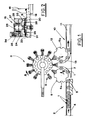
- the machine for filling bottles 1 with a liquid product has means 2 for feeding the said bottles to a carousel 3 which rotates about a vertical axis in the direction indicated by arrow A.
- Feed means 2 consist of a bottle 1 conveying line 4 along which there is an auger 5 which rotates axially in such a manner as to space the conveyed bottles 1 apart.
- Auger 5 is designed to operate in conjunction with a distributor 6, shaped like a star, for example, which rotates in the direction of arrow B.
- the bottles to be fed are held and guided by recesses 6a in distributor 6 and by ring guide 7 which partially surrounds the distributor itself.
- Carousel 3 receives bottles 1 fed by distributor 6 one by one at the point where the equally spaced grippers 8, mounted on the circumference of the carousel itself, are activated. Carousel 3 also mounts dispensing units, labelled 9 in the drawings, which fill the liquid product into bottles 1.
- a full bottle outfeed system 10 consisting of a conveyor line 11 and another distributor 12, shaped like a star, for example, which rotates in the direction of arrow C.
- the outgoing bottles are received by distributor 12 at the point where they are released by grippers 8 and are held and guided by recesses 12a in the distributor and by a ring guide 13 which partially surrounds the distributor.
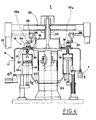
- dispensing units 9 consist of a plurality of cylinder and plunger assemblies mounted by carousel 3 which lines them up with grippers 8.
- Each of the said cylinder and plunger assemblies 14 is connected through a valve 15 to a liquid feed chamber 16 and to a filling nozzle 17 alternately.
- Chamber 16 is mounted on a platform 18 attached to the rotating part of carousel 3.
- Platform 18 is secured to the top of a vertical shaft 19, rotated continuously by the drive motor of the machine.
- Chamber 16 concentric with the axis of carousel 3, is fed through a tube 20 connected to a tank, which is not illustrated, outside the machine.
- Tube 20 is located above chamber 16, diametrically with respect to carousel 3, and is supported by a frame 21 attached to the fixed structure of the machine.
- Tube 20 is connected to a mouthpiece 22 leading out of chamber 16 in accordance with the axis of rotation of the carousel.
- valve 15 consists of a lower casing 23 fixed to carousel platform 18 and an upper casing 24 which rotates on a pin 25 about the vertical axis of valve 15 itself and in relation to fixed lower casing 23.
- Upper casing 24 has a cap 26 held by pin 25 and pushed axially by a spring 27 which presses down on casing 24.
- Lower casing 23 is crossed by a pair of parallel, vertical holes 28 and 29, which, at their bottom ends, are connected with a pair of ducts, respectively 30 and 31, made in platform 18.
- Duct 30 leads out of chamber 16, whilst duct 31 is connected to dispensing nozzle 17.
- Platform 18 is also crossed by a vertical hole 32, whose bottom end is connected to cylinder and plunger assembly 14 and whose top end extends into lower casing 23 of the valve.
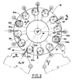
- the axes of holes 28, 29 and 32 are distributed around a circle concentric with the axis of rotation of upper valve casing 24.
- Upper, rotating casing 24 is crossed by an approximately semicircular channel 33 in a horizontal plane.
- channel 33 At each end and in the middle of channel 33 there are downward opening holes 33a, 33b and 33c which serve to connect hole 32 to ducts 30 and 31 alternately, in accordance with the angular position assumed by rotating valve casing 24.
- Cap 26 of rotating casing 24 has on its top an eccentric pin 34 which rotates axially and held by a sprung bolt 35.
- Pin 34 is designed to intercept a pair of cams 36 and 37, respectively first and second cam, during the rotation of carousel 3, the said cams being carried by fixed frame 21 of the machine in diametrically opposite positions in relation to the axis of the carousel itself.
- Cams 36 and 37 have a chamfered face designed to act as a sliding guide for pin 34.
- Cams 36 and 37 are supported by actuators 38 and 39 respectively driven in a vertical direction in such a manner that they can be lifted to positions 36a and 37a in which they are disengaged from pins 34. The raising of cams 36 and 37 make it possible for washing cycles to be performed on the machine.
- valve 15 switches the connection of cylinder and plunger assembly 14 from liquid suction duct 30 to duct 31 which conveys the liquid to nozzle 17.
- eccentric pin 34 of the valve is intercepted by cam 36, thus causing upper casing 24 of the valve to rotate in relation to lower, fixed casing 23.
- channel 33 of casing 24 is connected through holes 33a and 33b to hole 32 and to duct 31, thus enabling the liquid to flow out through the nozzle.
- cam 37 intercepts eccentric pin 34, causing casing 24 of valve 15 to rotate to the initial position, that is to say, with channel 33 connected to duct 30 and cylinder and plunger assembly 14. At the same time, the next suction stage begins and liquid flows into cylinder and plunger assembly 14.
- the device described constitutes a reliable, efficient means to supply a liquid product to the dispensing units 9 rotated by the carousel.
Applications Claiming Priority (2)
| Application Number | Priority Date | Filing Date | Title |
|---|---|---|---|
| IT00373590A IT1242879B (it) | 1990-11-14 | 1990-11-14 | Dispositivo per l'erogazione di sostanze liquide a organi rotanti, in particolare in macchine automatiche per il riempimento di contenitori con tali sostanze liquide. |
| IT373590 | 1990-11-14 |
Publications (2)
| Publication Number | Publication Date |
|---|---|
| EP0486440A1 true EP0486440A1 (de) | 1992-05-20 |
| EP0486440B1 EP0486440B1 (de) | 1994-06-08 |
Family
ID=11111582
Family Applications (1)
| Application Number | Title | Priority Date | Filing Date |
|---|---|---|---|
| EP91830492A Expired - Lifetime EP0486440B1 (de) | 1990-11-14 | 1991-11-12 | Vorrichtung zum Ausgeben von flüssigen Produkten zu drehbeweglichen Teilen, insbesondere für Getränkeabfüller |
Country Status (4)
| Country | Link |
|---|---|
| EP (1) | EP0486440B1 (de) |
| DE (1) | DE69102399T2 (de) |
| ES (1) | ES2055577T3 (de) |
| IT (1) | IT1242879B (de) |
Cited By (4)
| Publication number | Priority date | Publication date | Assignee | Title |
|---|---|---|---|---|
| EP0810180A1 (de) * | 1996-05-30 | 1997-12-03 | MARCHESINI GROUP S.p.A. | Mehrweg-Membranventil, insbesondere für Flüssigkeitsfüllmaschinen |
| FR2788046A1 (fr) * | 1999-01-06 | 2000-07-07 | Sidel Sa | Machine de remplissage comportant une vanne deportee |
| JP2015074490A (ja) * | 2013-10-11 | 2015-04-20 | サッポロビール株式会社 | 支持部材及び流体分配装置 |
| CN113828369A (zh) * | 2021-09-14 | 2021-12-24 | 苏州环美生物医疗科技有限公司 | 一种吸液装置 |
Families Citing this family (2)
| Publication number | Priority date | Publication date | Assignee | Title |
|---|---|---|---|---|
| NL2017196B1 (en) | 2016-07-20 | 2018-01-26 | Sluis Cigar Machinery Bv | Simulated cigarette parts reorienting apparatus |
| CN114950860B (zh) * | 2022-05-31 | 2023-11-07 | 中科纳通(重庆)电子材料有限公司 | 一种用于镍碳胶加工工艺的点胶机 |
Citations (4)
| Publication number | Priority date | Publication date | Assignee | Title |
|---|---|---|---|---|
| FR2179188A1 (de) * | 1972-04-05 | 1973-11-16 | Mather & Platt Ltd | |
| US4060109A (en) * | 1976-05-14 | 1977-11-29 | Kewpie Kabushiki Kaisha | Filling quantity regulating system in container filling apparatus |
| GB2067530A (en) * | 1980-01-17 | 1981-07-30 | Pont A Mousson | Filling arrangement for a bottling installation for filling bottles with liquids |
| EP0350974A2 (de) * | 1985-11-11 | 1990-01-17 | SIMONAZZI A. & L. S.p.A. | Kontinuierliche Rotations-Flaschenfüllvorrichtung |
-
1990
- 1990-11-14 IT IT00373590A patent/IT1242879B/it active IP Right Grant
-
1991
- 1991-11-12 EP EP91830492A patent/EP0486440B1/de not_active Expired - Lifetime
- 1991-11-12 ES ES91830492T patent/ES2055577T3/es not_active Expired - Lifetime
- 1991-11-12 DE DE69102399T patent/DE69102399T2/de not_active Expired - Fee Related
Patent Citations (4)
| Publication number | Priority date | Publication date | Assignee | Title |
|---|---|---|---|---|
| FR2179188A1 (de) * | 1972-04-05 | 1973-11-16 | Mather & Platt Ltd | |
| US4060109A (en) * | 1976-05-14 | 1977-11-29 | Kewpie Kabushiki Kaisha | Filling quantity regulating system in container filling apparatus |
| GB2067530A (en) * | 1980-01-17 | 1981-07-30 | Pont A Mousson | Filling arrangement for a bottling installation for filling bottles with liquids |
| EP0350974A2 (de) * | 1985-11-11 | 1990-01-17 | SIMONAZZI A. & L. S.p.A. | Kontinuierliche Rotations-Flaschenfüllvorrichtung |
Cited By (6)
| Publication number | Priority date | Publication date | Assignee | Title |
|---|---|---|---|---|
| EP0810180A1 (de) * | 1996-05-30 | 1997-12-03 | MARCHESINI GROUP S.p.A. | Mehrweg-Membranventil, insbesondere für Flüssigkeitsfüllmaschinen |
| FR2788046A1 (fr) * | 1999-01-06 | 2000-07-07 | Sidel Sa | Machine de remplissage comportant une vanne deportee |
| WO2000040505A1 (fr) * | 1999-01-06 | 2000-07-13 | Sidel | Machine de remplissage avec tetes de remplissage comportant chacune une vanne deportee vers le bas |
| US6533001B1 (en) | 1999-01-06 | 2003-03-18 | Sidel | Filling machine with filling heads that are respectively provided with a downward skewed valve |
| JP2015074490A (ja) * | 2013-10-11 | 2015-04-20 | サッポロビール株式会社 | 支持部材及び流体分配装置 |
| CN113828369A (zh) * | 2021-09-14 | 2021-12-24 | 苏州环美生物医疗科技有限公司 | 一种吸液装置 |
Also Published As
| Publication number | Publication date |
|---|---|
| IT9003735A0 (it) | 1990-11-14 |
| IT1242879B (it) | 1994-05-18 |
| DE69102399D1 (de) | 1994-07-14 |
| ES2055577T3 (es) | 1994-08-16 |
| EP0486440B1 (de) | 1994-06-08 |
| IT9003735A1 (it) | 1992-05-14 |
| DE69102399T2 (de) | 1994-11-24 |
Similar Documents
| Publication | Publication Date | Title |
|---|---|---|
| US7409971B2 (en) | Machine for dispensing fluid substance into containers | |
| US7114535B2 (en) | Circular motion filling machine and method | |
| US4901504A (en) | Filling and casing system | |
| EP0486439B1 (de) | Anordnung zum synchronen Antrieb von Einrichtungen zur Füllung und Containerbehandlung in Getränkeabfüllern | |
| US6832640B2 (en) | Device for gripping and handling bottles in a labeling machine and method of bottle filling/pressurising | |
| US5551491A (en) | Automatic carousel machine for the metered feeding and packaging of fluid products | |
| US4874076A (en) | Device for transferring packages | |
| EP1857087A1 (de) | Füllmaschine zum Füllen von Behältern mit zumindest einem Granulat | |
| US5158168A (en) | Container transfer device | |
| EP1864942B1 (de) | Behältertransportband für Abfüllanlagen | |
| GB2410021A (en) | System for filling and closing fluid containing cartridges | |
| EP0486440A1 (de) | Vorrichtung zum Ausgeben von flüssigen Produkten zu drehbeweglichen Teilen, insbesondere für Getränkeabfüller | |
| GB898385A (en) | Improvements in or relating to apparatus for filling containers | |
| CN103342327A (zh) | 颗粒香辣酱称量灌装生产线 | |
| EP0486438B1 (de) | Verfahren und Vorrichtung zum Befüllen von Behältern mit Flüssigkeiten | |
| USRE31393E (en) | Star-wheel indexing system for automatic filling machines | |
| EP3747561A1 (de) | Waschmaschine für behälter, insbesondere für produkte der pharmazeutischen industrie | |
| US3259152A (en) | Apparatus for filling and shaking a can | |
| JPH10305802A (ja) | 不定形容器充填装置 | |
| US1023074A (en) | Feed mechanism for bottling-machines. | |
| US3759012A (en) | Device for fitting caps to containers | |
| US3550648A (en) | Method and apparatus for filling multiple cavity containers with measured charges of liquid | |
| US2744368A (en) | Closure applying apparatus | |
| EP2200927B1 (de) | Vorrichtung zur verdeckelung von behältern in einer füllmaschine | |
| RU2098346C1 (ru) | Фасовочный автомат |
Legal Events
| Date | Code | Title | Description |
|---|---|---|---|
| PUAI | Public reference made under article 153(3) epc to a published international application that has entered the european phase |
Free format text: ORIGINAL CODE: 0009012 |
|
| AK | Designated contracting states |
Kind code of ref document: A1 Designated state(s): CH DE ES FR GB LI |
|
| 17P | Request for examination filed |
Effective date: 19921030 |
|
| 17Q | First examination report despatched |
Effective date: 19930615 |
|
| GRAA | (expected) grant |
Free format text: ORIGINAL CODE: 0009210 |
|
| AK | Designated contracting states |
Kind code of ref document: B1 Designated state(s): CH DE ES FR GB LI |
|
| PG25 | Lapsed in a contracting state [announced via postgrant information from national office to epo] |
Ref country code: CH Effective date: 19940608 Ref country code: LI Effective date: 19940608 |
|
| REF | Corresponds to: |
Ref document number: 69102399 Country of ref document: DE Date of ref document: 19940714 |
|
| ET | Fr: translation filed | ||
| REG | Reference to a national code |
Ref country code: ES Ref legal event code: FG2A Ref document number: 2055577 Country of ref document: ES Kind code of ref document: T3 |
|
| REG | Reference to a national code |
Ref country code: CH Ref legal event code: PL |
|
| PLBE | No opposition filed within time limit |
Free format text: ORIGINAL CODE: 0009261 |
|
| STAA | Information on the status of an ep patent application or granted ep patent |
Free format text: STATUS: NO OPPOSITION FILED WITHIN TIME LIMIT |
|
| 26N | No opposition filed | ||
| REG | Reference to a national code |
Ref country code: GB Ref legal event code: IF02 |
|
| PGFP | Annual fee paid to national office [announced via postgrant information from national office to epo] |
Ref country code: DE Payment date: 20081128 Year of fee payment: 18 |
|
| PGFP | Annual fee paid to national office [announced via postgrant information from national office to epo] |
Ref country code: FR Payment date: 20081118 Year of fee payment: 18 Ref country code: ES Payment date: 20081127 Year of fee payment: 18 |
|
| PGFP | Annual fee paid to national office [announced via postgrant information from national office to epo] |
Ref country code: GB Payment date: 20081127 Year of fee payment: 18 |
|
| GBPC | Gb: european patent ceased through non-payment of renewal fee |
Effective date: 20091112 |
|
| REG | Reference to a national code |
Ref country code: FR Ref legal event code: ST Effective date: 20100730 |
|
| PG25 | Lapsed in a contracting state [announced via postgrant information from national office to epo] |
Ref country code: FR Free format text: LAPSE BECAUSE OF NON-PAYMENT OF DUE FEES Effective date: 20091130 |
|
| PG25 | Lapsed in a contracting state [announced via postgrant information from national office to epo] |
Ref country code: DE Free format text: LAPSE BECAUSE OF NON-PAYMENT OF DUE FEES Effective date: 20100601 |
|
| PG25 | Lapsed in a contracting state [announced via postgrant information from national office to epo] |
Ref country code: GB Free format text: LAPSE BECAUSE OF NON-PAYMENT OF DUE FEES Effective date: 20091112 |
|
| REG | Reference to a national code |
Ref country code: ES Ref legal event code: FD2A Effective date: 20110307 |
|
| PG25 | Lapsed in a contracting state [announced via postgrant information from national office to epo] |
Ref country code: ES Free format text: LAPSE BECAUSE OF NON-PAYMENT OF DUE FEES Effective date: 20110304 |
|
| PG25 | Lapsed in a contracting state [announced via postgrant information from national office to epo] |
Ref country code: ES Free format text: LAPSE BECAUSE OF NON-PAYMENT OF DUE FEES Effective date: 20091113 |