EP3487192A1 - System und verfahren zur schätzung der position und ausrichtung einer mobilkommunikationsvorrichtung in einem bakenbasierten positionierungssystem - Google Patents
System und verfahren zur schätzung der position und ausrichtung einer mobilkommunikationsvorrichtung in einem bakenbasierten positionierungssystem Download PDFInfo
- Publication number
- EP3487192A1 EP3487192A1 EP18212987.4A EP18212987A EP3487192A1 EP 3487192 A1 EP3487192 A1 EP 3487192A1 EP 18212987 A EP18212987 A EP 18212987A EP 3487192 A1 EP3487192 A1 EP 3487192A1
- Authority
- EP
- European Patent Office
- Prior art keywords
- frequency
- light
- cycle
- light source
- modulation
- Prior art date
- Legal status (The legal status is an assumption and is not a legal conclusion. Google has not performed a legal analysis and makes no representation as to the accuracy of the status listed.)
- Withdrawn
Links
Images


Classifications
-
- G—PHYSICS
- G01—MEASURING; TESTING
- G01S—RADIO DIRECTION-FINDING; RADIO NAVIGATION; DETERMINING DISTANCE OR VELOCITY BY USE OF RADIO WAVES; LOCATING OR PRESENCE-DETECTING BY USE OF THE REFLECTION OR RERADIATION OF RADIO WAVES; ANALOGOUS ARRANGEMENTS USING OTHER WAVES
- G01S5/00—Position-fixing by co-ordinating two or more direction or position line determinations; Position-fixing by co-ordinating two or more distance determinations
- G01S5/16—Position-fixing by co-ordinating two or more direction or position line determinations; Position-fixing by co-ordinating two or more distance determinations using electromagnetic waves other than radio waves
-
- G—PHYSICS
- G01—MEASURING; TESTING
- G01C—MEASURING DISTANCES, LEVELS OR BEARINGS; SURVEYING; NAVIGATION; GYROSCOPIC INSTRUMENTS; PHOTOGRAMMETRY OR VIDEOGRAMMETRY
- G01C21/00—Navigation; Navigational instruments not provided for in groups G01C1/00 - G01C19/00
- G01C21/20—Instruments for performing navigational calculations
- G01C21/206—Instruments for performing navigational calculations specially adapted for indoor navigation
-
- H—ELECTRICITY
- H04—ELECTRIC COMMUNICATION TECHNIQUE
- H04B—TRANSMISSION
- H04B10/00—Transmission systems employing electromagnetic waves other than radio-waves, e.g. infrared, visible or ultraviolet light, or employing corpuscular radiation, e.g. quantum communication
- H04B10/11—Arrangements specific to free-space transmission, i.e. transmission through air or vacuum
- H04B10/114—Indoor or close-range type systems
- H04B10/1141—One-way transmission
-
- H—ELECTRICITY
- H04—ELECTRIC COMMUNICATION TECHNIQUE
- H04B—TRANSMISSION
- H04B10/00—Transmission systems employing electromagnetic waves other than radio-waves, e.g. infrared, visible or ultraviolet light, or employing corpuscular radiation, e.g. quantum communication
- H04B10/11—Arrangements specific to free-space transmission, i.e. transmission through air or vacuum
- H04B10/114—Indoor or close-range type systems
- H04B10/1149—Arrangements for indoor wireless networking of information
-
- H—ELECTRICITY
- H04—ELECTRIC COMMUNICATION TECHNIQUE
- H04B—TRANSMISSION
- H04B10/00—Transmission systems employing electromagnetic waves other than radio-waves, e.g. infrared, visible or ultraviolet light, or employing corpuscular radiation, e.g. quantum communication
- H04B10/11—Arrangements specific to free-space transmission, i.e. transmission through air or vacuum
- H04B10/114—Indoor or close-range type systems
- H04B10/116—Visible light communication
-
- H—ELECTRICITY
- H04—ELECTRIC COMMUNICATION TECHNIQUE
- H04W—WIRELESS COMMUNICATION NETWORKS
- H04W4/00—Services specially adapted for wireless communication networks; Facilities therefor
- H04W4/02—Services making use of location information
-
- H—ELECTRICITY
- H04—ELECTRIC COMMUNICATION TECHNIQUE
- H04W—WIRELESS COMMUNICATION NETWORKS
- H04W4/00—Services specially adapted for wireless communication networks; Facilities therefor
- H04W4/02—Services making use of location information
- H04W4/025—Services making use of location information using location based information parameters
- H04W4/026—Services making use of location information using location based information parameters using orientation information, e.g. compass
-
- H—ELECTRICITY
- H04—ELECTRIC COMMUNICATION TECHNIQUE
- H04W—WIRELESS COMMUNICATION NETWORKS
- H04W4/00—Services specially adapted for wireless communication networks; Facilities therefor
- H04W4/02—Services making use of location information
- H04W4/029—Location-based management or tracking services
-
- H—ELECTRICITY
- H04—ELECTRIC COMMUNICATION TECHNIQUE
- H04W—WIRELESS COMMUNICATION NETWORKS
- H04W4/00—Services specially adapted for wireless communication networks; Facilities therefor
- H04W4/30—Services specially adapted for particular environments, situations or purposes
-
- H—ELECTRICITY
- H04—ELECTRIC COMMUNICATION TECHNIQUE
- H04W—WIRELESS COMMUNICATION NETWORKS
- H04W4/00—Services specially adapted for wireless communication networks; Facilities therefor
- H04W4/30—Services specially adapted for particular environments, situations or purposes
- H04W4/33—Services specially adapted for particular environments, situations or purposes for indoor environments, e.g. buildings
-
- H—ELECTRICITY
- H04—ELECTRIC COMMUNICATION TECHNIQUE
- H04W—WIRELESS COMMUNICATION NETWORKS
- H04W4/00—Services specially adapted for wireless communication networks; Facilities therefor
- H04W4/30—Services specially adapted for particular environments, situations or purposes
- H04W4/40—Services specially adapted for particular environments, situations or purposes for vehicles, e.g. vehicle-to-pedestrians [V2P]
-
- H—ELECTRICITY
- H05—ELECTRIC TECHNIQUES NOT OTHERWISE PROVIDED FOR
- H05B—ELECTRIC HEATING; ELECTRIC LIGHT SOURCES NOT OTHERWISE PROVIDED FOR; CIRCUIT ARRANGEMENTS FOR ELECTRIC LIGHT SOURCES, IN GENERAL
- H05B45/00—Circuit arrangements for operating light-emitting diodes [LED]
- H05B45/10—Controlling the intensity of the light
- H05B45/12—Controlling the intensity of the light using optical feedback
-
- G—PHYSICS
- G01—MEASURING; TESTING
- G01S—RADIO DIRECTION-FINDING; RADIO NAVIGATION; DETERMINING DISTANCE OR VELOCITY BY USE OF RADIO WAVES; LOCATING OR PRESENCE-DETECTING BY USE OF THE REFLECTION OR RERADIATION OF RADIO WAVES; ANALOGOUS ARRANGEMENTS USING OTHER WAVES
- G01S2205/00—Position-fixing by co-ordinating two or more direction or position line determinations; Position-fixing by co-ordinating two or more distance determinations
- G01S2205/01—Position-fixing by co-ordinating two or more direction or position line determinations; Position-fixing by co-ordinating two or more distance determinations specially adapted for specific applications
- G01S2205/02—Indoor
Definitions
- This disclosure relates generally to a system and method for estimating the position and orientation of a mobile device with respect to a light-based positioning system.
- Described herein are techniques for estimating the position and orientation of a light-detecting mobile communications device (e.g., cellular telephone, tablet computer, wearable computing device, electronically enhanced eyeglasses) by identifying light beacons in the vicinity of the mobile device and by compensating at least in part for motion of the mobile device, the presence of visual noise, and local irregularities in the Earth's magnetic field.
- a light-detecting mobile communications device e.g., cellular telephone, tablet computer, wearable computing device, electronically enhanced eyeglasses
- Indoor positioning services relate to methods in which networks of devices and algorithms are used to locate mobile devices within buildings.
- Indoor positioning is regarded as a key component of location-aware mobile computing and is a critical element in providing augmented reality (AR) services.
- Location-aware computing relates to applications that utilize a mobile device user's location to provide content relevant to that location. Additionally, AR is a technology that overlays a virtual space onto a real (physical) space. To successfully enable AR and location-aware computing, accurate indoor positioning is a key requirement.
- indoor positioning and AR services may include displaying on a user's mobile device in real time a spatial map which includes "you are here" information; such information not only should be accurate enough to assist user navigation (e.g., in a retail space) but should be presented in a manner that is clear and agreeable to the user.
- GPS Global Positioning System
- WiFi and Bluetooth wireless access points have also been explored for indoor positioning.
- RSSI received signal strength indication
- Ultrasonic techniques which transmit acoustic waves to microphones, can also be used to approximate indoor position.
- ultrasonic sound waves operate at lower frequencies than systems based on WiFi and attenuate significantly when passing through walls. This attenuation, which limits the spatial reach of waves from an ultrasound source, potentially makes ultrasonic techniques more accurate than WiFi or Bluetooth techniques.
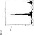
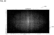
- an illustrative light-source detection scheme described herein depends on the detection of spectral peaks (i.e., peaks in the frequency domain) that correspond to identification signals emitted by light sources.
- the spectrum of a digital image (or other data obtained by sensing light, whether using an image-forming camera, a non-image-forming sensor, or both) is estimated by calculating a Fast Fourier Transform (FFT) of the image or a signal derived by averaging from the data.
- FFT Fast Fourier Transform
- a second limitation of indoor positioning is the presentation of location information in a user-friendly way.
- a beacon-based positioning system that may show a user of a mobile device their approximate position and orientation on a map displayed on the mobile device, sudden movement of the user's position indicator from one point to another (e.g., from one beacon location to another beacon location, or to the centroid of two or more beacon locations) tends to be disconcerting or irksome to the user. It is therefore desirable to form an estimate of a user's position that moves smoothly, or nearly so, between points on a map.
- orientation information be delivered to users of an indoor position system, including the bearers of mobile devices who may be viewing maps of their spatial context on their device displays.
- Many mobile devices contain a compass or magnetometer that provides heading or orientation information by sensing the Earth's magnetic field.
- the Earth's magnetic field may, in effect, be locally distorted by the proximity of masses of metal or devices that generate magnetic fields. In such areas, raw device measurements of orientation may be misleading. It is therefore desirable to assure that a user's map is accurately oriented.
- a lighting device comprises a light source, a modulator coupled to the light source, and a processor coupled to the modulator.
- the processor is configured to control the light source to emit visible light for general illumination within a space and control the modulator to modulate the intensity of visible light emitted by the light source based on a signal comprising at least two superimposed sinusoids and in accordance with at least two frequencies of the at least two superimposed sinusoids such that the at least two superimposed sinusoids are simultaneously broadcast.
- a physical location of the lighting device within the space corresponds to a location defined by an x,y coordinate system over a planar area encompassing the space.
- a frequency of a first of the at least two superimposed sinusoids has a defined relationship to a value of the x coordinate of the physical location of the lighting device in the x,y coordinate system.
- a frequency of a second of the at least two superimposed sinusoids has a defined relationship to a value of the y coordinate of the physical location of the lighting device in the x,y coordinate system.
- a method comprises steps to emit, by an artificial light source, visible artificial light for general illumination within a space and modulate, by a modulator, the intensity of visible artificial light emitted by the light source to simultaneously broadcast at least two superimposed sinusoids modulated on the emitted visible artificial light.
- a physical location of the artificial light source within the space corresponds to a location defined by an x,y coordinate system over a planar area encompassing the space.
- a frequency of a first of the at least two superimposed sinusoids for example, has a defined relationship to a value of an x coordinate of the physical location of the artificial light source in the x,y coordinate system.
- a frequency of a second of the at least two superimposed sinusoids for example, has a defined relationship to a value of a y coordinate of the physical location of the artificial light source in the x,y coordinate system.
- a mobile device comprises an image sensor, a wireless interface configured to communicate through a network over a wireless medium, a processor coupled to the image sensor and the wireless interface, a memory and software in the memory to be run by the processor.
- running of the software by the processor configures the mobile device to implement functions.
- One implemented function operates the image sensor to capture one or more images including a modulated visible light signal transmitted from a visible light source located within a space.
- the modulated visible light signal includes, for example, at least two superimposed sinusoids.
- Another implemented function demodulates the modulated visible light signal from the captured one or more images to obtain at least a frequency of a first of the at least two superimposed sinusoids and a frequency of a second of the at least two superimposed sinusoids.
- Yet another implemented function infers, based at least in part on the obtained frequencies, a value for an x coordinate.
- the x coordinate for example, is part of an x,y coordinate system over a planar area encompassing the space.
- Still another implemented function infers, based at least in part on the obtained frequencies, a value for a y coordinate.
- the y coordinate for example, is part of the x,y coordinate system.
- a further implemented function determines, based on the inferred x and y coordinates, a physical location of the visible light source.
- a method comprises a step to capture, via an image sensor of a mobile device, one or more images including a modulated visible light signal transmitted from a visible light source located within a space.
- the modulated visible light signal for example, includes at least two superimposed sinusoids.
- the method further comprises a step to demodulate the modulated visible light signal from the captured one or more images to obtain at least a frequency of a first of the at least two superimposed sinusoids and a frequency of a second of the at least two superimposed sinusoids. Further steps include inferring, based at least in part on the obtained frequencies, a value for an x coordinate and inferring, based at least in part on the obtained frequencies, a value for a y coordinate.
- the x and y coordinates are part of an x,y coordinate system over a planar area encompassing the space
- the method still further comprises a step to determine, based on the inferred x and y coordinates, a physical location of the visible light source.
- the present disclosure relates, for example, to a method for frequently updating an estimate of a mobile device's position with respect to one or more beacon light sources.
- the method updates a device position estimate (e.g., a two-dimensional position estimate) as a sum of weighted position vectors derived from detections by the device of beacons having previously determined locations.
- a device position estimate e.g., a two-dimensional position estimate
- a light-sensing apparatus e.g., forward-facing camera, rear-facing camera, and/or other light-sensing device comprised by the mobile device
- a light-sensing apparatus e.g., forward-facing camera, rear-facing camera, and/or other light-sensing device comprised by the mobile device
- acquire digital images or non-image data
- the images are processed in a manner described herein in order to detect the presence of one or more beacon light sources
- an estimate of the mobile device's position is modified (updated) based on the one or more beacon light sources detected. Updates to the position estimate may be made at a rate limited by the image frame acquisition rate of the mobile device.
- the position estimate changes discretely both in time (i.e., upon beacon detection in image frames) and in space (by vector increments based on beacon detections), but in general, the position estimate will be perceived by a user as changing smoothly or nearly so.
- “camera” is to be construed broadly as referring, as appropriate, not only to image-sensing devices but to all optical sensors capable of acquiring data that contain light-encoded information.
- image is to be construed broadly as referring, as appropriate, to any data set, however obtained, that may contain light-encoded information.
- Various examples employ noise reduction techniques in images to enable more sensitive and accurate detection of beacon light sources as a basis for position-estimate updating.
- Such techniques include, but are not limited to, (a) background subtraction employing multiple images of a single scene or portions thereof and (b) deliberate defocusing of images to mitigate the potentially confounding presence of regular patterns. Defocusing effectively increases signal-to-noise ratio in various embodiments of the present invention.
- a mobile device's sensed orientation e.g., compass heading
- the correction to be applied may vary with the estimated location of the mobile device (e.g., in different parts of a retail space) and with time, as local deviations from the earth magnetic field may change when equipment, wiring, and the like are installed or repositioned.
- a local correction to be applied may also be specific to the particular model of mobile device in question, as different device models may experience different deviation errors even under identical environmental conditions.
- Various examples employ adaptive, crowd-sourced data collection from one or more mobile devices to update the corrections to be applied to the compass headings of one or more models of mobile device.
- the frequencies of signals transmitted by light sources are "swept" or varied through time, either continuously or in discrete increments, in order to assure robust detection of the signals regardless of the exposure parameters independently selected by a mobile device (e.g., exposure time of a photograph of video frame).
- the physical coordinates of a light source are encoded by modulating the output of the light source.
- Such encoding may be achieved by a variety of methods in various embodiments: such methods include, but are not limited to, (a) the simultaneous modulation of light-source brightness by two sinusoids of different frequency and amplitude in a single frequency band, (b) the simultaneous modulation of light-source brightness by two sinusoids of different frequency and amplitude in two nonoverlapping frequency bands, or (c) the simultaneous modulation of light-source brightness by three sinusoids of different frequency in a single frequency band.
- the frequencies of such positional information signals may be "swept" or varied through time, either continuously or in discrete increments, in order to mitigate the effects of destructive interference by multiple lights illuminating overlapping areas and so facilitate robust detection of the signals.
- the duration and other aspects of such sweeping may be varied in a random or pseudorandom manner in order to minimize or substantially eliminate destructive interference at any point in the working space of the system.
- Systems and methods are provided that disclose providing a positioning service for devices based on light received from one or more light sources.
- This light-based positioning service uses light information transmitted by each light source to determine the position of the device.
- the device captures the one or more light sources and is then able to detect the information transmitted by each of the light sources.
- the light information may include an identification code that is used to identify the position of the light source. By capturing more than one light source on the device the accuracy of the device's position may be improved.
- the position information may then be used to provide relevant content information to the user.
- the light sources are each independent beacons that transmit individual identification information through light.
- Yet another embodiment includes a system by which a mobile device 103 may receive content based upon identification information received from either one or more LED light sources.
- the identification information is used to access a database that correlates LED lights and content.
- An example of such a use case is a mobile device user in a museum, who receives identification information from a light source illuminating an exhibit, and then uses the received identification information to obtain additional content about the exhibit.
- FIG. 1 represents a mobile device 103 receiving light 102 from a LED light source 101.
- the LED light source 101 may be any lighting source used for general purpose, spot illumination, or backlighting.
- the LED light source may come in several form factors but is not limited to: Edison screw in, tube style, large and small object backlighting, or accent lighting spots and strips.
- any form of LED light is considered as a potential source capable of transmitting information.
- Light 102 is a modulated LED light source 101, and is part of the visible electromagnetic wireless spectrum.
- LEDs are considered digital devices which may be rapidly switched on and off, to send signals above the rate that the human eye can see. This allows them to be exploited to send digital data through the visible light itself.
- modulating the LEDs turning them on and off rapidly, one may send digital information that is unperceivable to the human eye, but is perceivable by applicable sensors, including but not limited to image sensors and other types of photosensors.
- OOK On Off Keying
- ASK amplitude-shift keying
- the carrier wave remains unchanged as this is an inherent property of the light itself.
- the carrier wave corresponding to a blue light signal is uniquely different than the carrier wave corresponding to a red light signal. While these two signals differ only in the wavelength specific to their perceived color, they can be perceived as two discrete signals.
- CMOS complementary metal-oxide-semiconductor
- CCD charge-coupled device
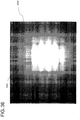
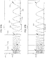
- the image appears to have alternating dark/white stripes.
- the stripes are a direct result of the rolling shutter mechanism, and their width is proportional to the frequency of the pulse width modulated (PWM) signal. Higher frequencies correspond to narrower stripes, and lower frequencies result in wider stripes. Practical frequency ranges for use with this technique are between 60Hz and 5000Hz. This technique allows one to exploit the rolling shutter mechanism to recover digital data from an optically encoded signal.
- PWM pulse width modulated
- DPR has the potential for much higher data rates than both OOK and frequency shift keying (FSK).
- FSK and OOK the camera's frame rate limits the data rate.
- the highest possible data rate is half of the frame rate, since each symbol spans over two frames.
- DPR modulation a single frame is sufficient for capturing the transmitted symbol.
- symbols are not "binary" - there are can be as many as 30 different possibilities for a symbol.
- LED light sources In addition to LED light sources, other types of light sources are also capable of transmitting information through modulation. Alternative incandescent and fluorescent technologies can also be exploited to achieve data transmission, however the circuitry is more complex because the turn-on and turn-off times of incandescent and fluorescent lights are subject to additional factors.
- the modulation frequency of the light source is highly dependent on the receiving circuitry. While incandescent and fluorescent technologies generally do not "flicker" on and off during the course of normal operation, LED lighting sources are sometimes designed to flicker above the rate which the eye can see in order to increase their longevity, and consume less power. Most humans cannot see flicker above 60Hz, but in rare instances can perceive flicker at 100Hz to 110Hz. To combat this, lighting manufacturers design flicker above 200Hz into their lighting products.
- the reception of optically transmitted information is particularly interesting when used as an indoor positioning system.
- the physical locations of light sources may be used to approximate the relative position of a mobile device 103 within line of sight.
- the mobile device 103 may use information to determine position of the mobile device.
- the mobile device may access a data source containing information about where the lights are physically located to determine position. This data source may be stored locally, or in the case where the mobile device 103 has a network connection, the data source may be stored on an external server 703.
- the mobile device 103 may optionally download a "map pack" containing the information used to locate itself indoors, instead of relying on an external server 703.
- the mobile device 103 would first use an alternative existing technique for resolving its position and would use the gained location information to download the appropriate map pack.
- the techniques for receiving geo-location information include, for example, GPS, GSM, WiFi, user input, accelerometer, gyroscope, digital compass, barometer, Bluetooth, and cellular tower identification information. These techniques may also be used to fill gaps between when a position of the mobile device is determined using the light-based technique. For example, a mobile device may be placed at times so its camera does not capture light sources.
- the map pack would contain a map 902 of the indoor space the user is entering, locations of the lights from some sort of existing or third-party lighting plan 1103, and any location-dependent content 903 for the mobile device 103 to consume. Any requests for location information would simply access data stored locally on the mobile device 103, and would not need to access a remote server via a network 601.
- the indoor location reception and calculation may happen with little to no user input.
- the process operates as a background service, and reads from the receiving module without actually writing them to the display screen of the mobile device. This is analogous to the way WiFi positioning operates, signals are read in a background service without requiring user interaction.
- the results of the received information may be displayed in a number of ways, depending on the desired application.
- the user would see an identifying marker overlaid on a map of the indoor space they are moving around in.
- the user might see a mobile media, images, text, videos, or recorded audio, about the objects they are standing in front of.
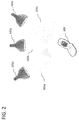
- FIG. 2 is a representation of a mobile device 103 receiving identification information 102a-102c from multiple LED light sources 101a-101c. Each light source is transmitting its own unique piece of information. In order to identify its position or receive location-based content, the mobile device 103 may then use the received information to access a database 802 containing information about the relative positions of the LED light sources 101a-101c and any additional content 903. When three or more sources of light are in view, relative indoor position may be determined in three dimensions. The position accuracy decreases with less than three sources of light, yet remains constant with three or more sources. With the relative positions of lights 101a-101c known, the mobile device 103 may use photogrammetry to calculate its position, relative to the light sources.
- Photogrammetry is a technique used to determine the geometric properties of objects found in photographic images.
- photogrammetry refers to utilizing the corresponding positions of LED light sources, and their positions in 3-D space, to determine the relative position of a camera equipped mobile device.
- three unique sources of light are seen by the camera on a mobile device, three unique coordinates may be created from the various unique combinations of 101a-101c and their relative positions in space can be determined.
- the following scenario may be considered.
- the sources appear brighter relative to the other pixels on the image.
- Thresholds may then be applied to the image to isolate the light sources. For example, pixel regions above the threshold are set to the highest possible pixel value, and the pixel regions below the threshold are set to the minimum possible pixel value. This allows for additional image processing to be performed on the isolated light sources.
- the end result is a binary image containing white continuous "blobs" where LED light sources are detected, and dark elsewhere where the sources are not detected.
- a blob detection algorithm may then be used to find separate LED light sources.
- a minimum of three separate LED blobs are used to resolve the 3-D position of a mobile device 103.
- Each LED blob represents a "region of interest" for the information reception, and is simultaneously transmitting a unique piece of information via the modulated visible signal from the light source.
- each region of interest is processed independently of other regions of interest and is considered to be uniquely identifiable.
- a center of mass calculation for each region may be performed to determine the pixel coordinates of the center of each LED light source. This center of mass calculation is performed for each frame to track the regions of interest as they move around the image.
- a detection algorithm captures multiple image frames for each region of interest in order to receive the visible light signal contained in each blob. For each frame in a detected region of interest, a threshold algorithm determines whether the frame contains a "1" (in the case of an aggregate pixel value above the threshold), or a "0" (in the case of an aggregate pixel value lower than the threshold). The threshold algorithm is used since the communication is asynchronous, so the camera receiver period may overlap between the transmission of a "1" and a "0" from the LED light source.
- the result of converting successive image frames in a region of interest to binary values is in essence a down-sampled digital version of the signal received from the LED light source.
- demodulation of the down-sampled digital signal is used to recover the transmitted bits. This down sampling is used due to the fact that the signal modulation frequency should be above the rate at which the human eye can see, and the image sensor frame rate is typically limited to 15-30 fps.
- the mobile device 103 processes data on a frame-by-frame basis. Each frame is split into separate regions of interest, based on the detection of light sources. For each region of interest, a thresholding algorithm is used to determine whether a given region is "on” or “off”. This is done by taking the average pixel value for the region and comparing it to the threshold value. If the region is "on”, the demodulator assumes the light source has just transmitted a "1". If the region is "off”, the demodulator assumes the light source has sent a "0". The result of this is the equivalent of a 1-bit analog-to-digital conversion (ADC), at a sampling rate which is equal to the frame rate of the camera.
- ADC analog-to-digital conversion
- the results of the ADC conversation are stored in a circular buffer.
- a sliding correlator is applied to the buffer to look for the presence of start bits 402. If start bits 402 are found, the demodulation algorithm assumes it is reading a valid packet of information 401 and proceeds to capture the rest of the transmission. Two samples are used for each bit, so the algorithm creates a linear buffer that is twice the size of the remaining packet. Each subsequent ADC is written sequentially to the linear buffer. When the linear buffer is filled, the demodulation algorithm performs a Fast Fourier Transform (FFT) on the buffer to recover the transmitted signal.
- FFT Fast Fourier Transform
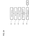
- FIG. 3 describes internal components commonly found in LED light source 101 with the addition components to allow for the transmission of optical signals.
- the LED light source 101 typically contains an alternating current (AC) electrical connection 301 where it connects to an external power source, an alternating current to direct current (AC/DC) converter 302 which converts the AC signal from the power source into an appropriate DC signal, a modulator 304 which interrupts power to the LEDs in order to turn them on and off, a microcontroller 305 which controls the rate at which the LEDs are modulated, and a LED driver circuit 303 which provides the appropriate amount of voltage and current to the LEDs.
- AC alternating current
- AC/DC alternating current to direct current
- Electrical connection 301 is an electrical source that is used to supply power to the LED light source 101. This most commonly comes in the form of a 120 Volt 60 Hz signal in the United States, and 230 Volt 50 Hz in Europe. While depicted in FIG. 3 as a three pronged outlet, it may also take the form of a two terminal Edison socket which the bulb is screwed into, or a bundle of wires containing a live, neutral, and/or ground. When considering other forms of lighting such as backlighting and accent lighting, the electrical connection may also come in the form of a DC source instead of an AC source.
- LED light sources contain an AC/DC converter 302 that converts the alternating current from the power source 301 to a direct current source used internally by the components found inside the bulb or light source.
- the converter takes the alternating current source commonly found in existing lighting wiring and converts it to a direct current source.
- LED light sources generally use direct current, therefore an AC/DC converter is found in most lighting products regardless of form factor.
- LED driver 303 provides the correct amount of current and voltage to the LEDs contained inside the lighting source. This component is commonly available and may have either a constant-current or constant-voltage output.
- the LEDs found inside most lighting sources are current-controlled devices, which require a specific amount of current in order to operate as designed. This is important for commercial lighting products because LEDs change color and luminosity in regards to different currents.
- the LED driver circuitry is designed to emit a constant amount of current while varying the voltage to appropriately compensate for the voltage drops across each LED.
- there are some high voltage LEDs which require a constant voltage to maintain their color and luminosity. For these cases the LED driver circuitry provides a constant voltage while varying the current.
- Modulator 304 serves the function of modulating the LED light source 101 on and off to optically send light 102 signals.
- the circuits featuring the modulator may simply consist essentially of solid-state transistors controlled by a digital input.
- the modulator 304 turns the LEDs on and off by allowing or preventing current flow. When current flows through the modulator with the switches closed the LEDs turn on, and when the switches are open in the modulator no current can flow and the LEDs turn off.
- the modulator is controlled by an additional logic component, it has the ability to send repeating patterns of on/off signals in order to transmit digital data through the visible light 102.
- the modulator interfaces directly in between the AC/DC converter 302 and the LED driver 303, and is controlled by a microcontroller 305.
- the microcontroller 305 provides the digital input signal to the modulator unit 304. This function may also be achieved using a field-programmable gate array (FPGA), but typically consumes more power with added complexity.
- the microcontroller's 305 task is to send a pre-determined sequence of signals to the modulator 304 which then interfaces with the LED driver 303 to modulate the outgoing visible light from the LED source 101.
- the microcontroller contains a nonvolatile memory storage area, which stores the identification code of the light signal. Examples of possible nonvolatile memory sources include programmable read only memory (PROM), electrically erasable programmable read only memory (EEPROM), or Flash.
- the microcontroller 305 contains a digital output pin, which is used to modulate the light output. To generate the output signal waveforms, timer modules within the microcontroller 305 are used. Typical logic levels for the digital output are 3.3V and 5V. This digital output feeds into the modulator 304 which interrupts the driver circuit 303 for the LED light source 101. Alternatively, if the LED light source requires lower power, such as backlighting or individual LED diodes, the output of the microcontroller 305 could also be used to drive the light sources directly.
- the sequence of signals sent from the microcontroller 305 determines the information that is transmitted from the LED light source 101.
- FIG. 4 describes the information 401 format of the optically transmitted information from the light 102.
- each packet of information contains some sort of starting bit sequence, which indicates the beginning of a packet, followed by data 403, and some sort of error detection identifier.
- the size and position of each portion of information is dependent on the application and is also constrained by requirements of the receiving device.
- Each packet of information 401 transmitted from the LED light source 101 contains a sequence of starting bits 402, followed by data 403, and then terminated with an error detection code 404. Since the LED light sources 101 are continually broadcasting information 401, erroneous packets are simply discarded while the receiver listens for the starting bits 402, indicating the beginning of the next packet. In cases where multiple sources of light are observed by a mobile device 103, multiple pieces of information 401 are received simultaneously.
- Information 401 describes the encoded information that is transmitted by the LED light source 101.
- the information 401 is contained in a packet structure with multiple bits which correspond to numeric integer values.
- the data 403 portion of the information packet may include unique ID codes 701. Currently the data 403 size is set to 10 bits, but may be of varying length. Each bit represents a binary "1" or "0", with 10 bits of data 103 corresponding to 1024 possible values. This corresponds to 1024 unique possibilities of ID codes 701 before there is a duplicate.
- the ID code may include location information in the ID code that provides a general indication of geographical location of the light. This geographical location information may be used to more quickly locate light source information that is used in determining indoor positioning on the mobile device. For example, the geographical information may point to a database to begin searching to find relevant information for positioning.
- the geographical information may include existing location identifiers such as area code, zip code, census tract, or any other customized information.
- the ID code 701 is static and is assigned during the calibration phase of the LED light source 101 during the manufacturing process.
- One method to assign the ID code 701 is to place instructions to generate a random code in the nonvolatile memory. Once the LED light source 101 is powered on the microcontroller reads the ID code 701 from the nonvolatile memory storage area, and then uses this code for broadcasting each and every time it is subsequently powered on. Since the ID code 701 is static, once it is assigned it will be forever associated locally to the specific LED light source 101 which contains the microcontroller 305.
- FIG. 5 describes the components found in mobile devices 103 that are capable of receiving optical information.
- the mobile device contains an image sensor 501 to capture optically transmitted information, a central processing unit 502 to decipher and manage received information, and a network adapter 503 to send and receive information.
- Photosensors are devices which receive incoming electromagnetic signals, such as light 102, and convert them to electrical signals.
- image sensors are arrays of photosensors that convert optical images into electronic signals. The ability to receive signals from multiple sources is an important benefit when using image sensors for receiving multiple optical signals.
- Image sensor 501 is a typical sensor which is found in most smart devices. The image sensor converts the incoming optical signal into an electronic signal. Many devices contain complementary metal-oxide-semiconductor (CMOS) image sensors; however, some still use charge-coupled devices (CCD). CMOS image sensors are the more popular choice for mobile devices due to lower manufacturing costs and lower power consumption. There are several tradeoffs to consider when choosing an image sensor to perform photogrammetry on multiple LED light sources 101. One tradeoff is between the camera resolution and the accuracy of the photogrammetric process when triangulating between multiple light sources - increasing the number of pixels will increase the accuracy. There is also another tradeoff between the data rate of the transmission and the sampling rate (in frames per second) of the camera.
- CMOS complementary metal-oxide-semiconductor
- the data rate (in bits/second) is half the frame rate of the camera (e.g., a 30 fps camera will receive 15 bps). And finally when determining the length of the information 401 packet, the larger the size the longer the reception period, as more bits generally requires longer sampling periods to capture the full message.
- CPU 502 is typically a generic CPU block found in most smart devices.
- the CPU 502 is in charge of processing received information and sending relevant information to the network adapter 503. Additionally the CPU has the ability to read and write information to embedded storage 504 within the mobile device 103.
- the CPU 502 may use any standard computer architecture. Common architectures for microcontroller devices include ARM and x86.
- the network adapter 503 is the networking interface that allows the mobile device 103 to connect to cellular and WiFi networks.
- the network connection is used in order for the mobile device 103 to access a data source containing light ID codes 701 with their corresponding location data 702. This may be accomplished without a data connection by storing location data 702 locally to the mobile device's 103 internal storage 504, but the presence of a network adapter 503 allows for greater flexibility and decreases the resources needed.
- the network adapter 503 is also used to deliver location dependent content to the mobile device when it is connected to a larger network 601.
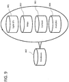
- FIG. 6 is a representation of multiple LED sources sending light 102a-d containing identification information 102 to multiple mobile devices 103a-103b.
- the light sources are acting as non-networked broadcast beacons; there are no networking modules or physical data wires connecting them. This property is desirable when looking towards a commercial installation of numerous LED light sources 103a-103b, as additional wiring and networking will not be required.
- the mobile devices have the ability to send and receive additional information from a local source or a network 601. Once the mobile device 103 receives identification information 401 from the light sources, it then asks a local or remote source for additional information.
- Enclosed area 602 is a spatial representation of an enclosed room containing four LED sources 101a-101d and two mobile devices 103a-103b, meaning that they may operate next to each other without interference.
- the received image feed from the mobile device sees one or more distinct bright sources of light, it has the ability to differentiate and receive the unique information without interference. Because the light capture is based on line of sight, interference is mitigated. In this line of sight environment, interference may arise when the light capture mechanism of the mobile device is blocked from the line of sight view of the light source.
- Network 601 represents a data network that may be accessed by mobile devices 103a-103b via their embedded network adapters 503.
- the network may consist of a wired or wireless local area network (LAN), with a method to access a larger wide area network (WAN), or a cellular data network (Edge, 3G, 4G, LTS, etc).
- LAN local area network
- WAN wide area network
- Edge 3G, 4G, LTS, etc.
- the network connection provides the ability for the mobile devices 103a-103b to send and receive information from additional sources, whether locally or remotely.
- FIG. 7 describes how the mobile device 103 receives location data 702.
- the mobile device 103 sends decoded ID codes 701 through a network 601 to a server 703, which sends back location information 702.
- the decoded ID codes 701 are found in the information 401, which is contained in the optically transmitted signal.
- the mobile device 103 After receiving this signal containing a unique ID code 701 the mobile device 103 sends a request for location data 702 to the server 703, which sends back the appropriate responses.
- the request could include other sensor data such as but not limited to GPS coordinates and accelerometer/gyroscope data, for choosing between different types of location data 702 and any additional information.
- Location data 702 is the indoor location information which matches the received information 401.
- the location data 702 corresponds to indoor coordinates which match the ID code 701, similar to how outdoor GPS tags known locations of interest with corresponding information.
- the location data 702 could also contain generic data associated with the light identification information 401. This could include multimedia content, examples of which include recorded audio, videos, and images.
- the location data 702 may also vary depending, for example, on other criteria such as temporal criteria, historical criteria, or user-specified criteria.
- the temporal criteria may include the time of day.
- the historical criteria may include user location history (e.g., locations visited frequently), Internet browsing history, retail purchases, or any other recorded information about a mobile device user.
- the user-specified criteria may include policies or rules setup by a user to specify the type of content they wish to receive or actions the mobile device should take based on location information.
- the user-specified criteria may include how the mobile device behaves when the user is close to an item that is on sale.
- the user may specify that a coupon is presented to the user, or information about the item is presented on the mobile device.
- the information about the item may include videos, pictures, text, audio, and/or a combination of these that describe or relate to the item.
- the item may be something that is for sale, a display, a museum piece, or any other physical object.
- Server 703 handles incoming ID codes 701, and appropriately returns indoor location data 702 to the mobile devices 103.
- the handling may include receiving incoming ID codes, searching databases to determine matches, calculating position coordinates based on the ID codes, and communicating indoor location data 702. Since the LED light sources 101 are acting as "dumb" one-way communication beacons, it is up to other devices to determine how to use the ID codes to calculate position information and deliver related content.
- the server 703 may include the information used to link ID codes 701 to physical spaces and to deliver location-specific content.
- the server is designed to handle the incoming requests in a scalable manner, and return results to the mobile devices in real-time.
- FIG. 8 delves into location-specific areas 801 containing databases 802 and web services 803.
- the areas 801 represent a subset of databases 802 and web services 803 for individual locations where there are installed LED light sources 101.
- the server 703 directly communicates with these installations, which have their own separate sets of information.
- databases 802 represent the stored information pertaining to a specific area 801
- the web services 803 represent services which allow users, customers, administrators, and developers access to the ID codes, indoor locations, and other information.
- the server 703 In order to send relevant information, after each received ID code 701, the server 703 requests information pertaining to the specific area 801. Contained in each area 801, are databases which contain information corresponding to the specific ID code 701. This information can take multiple formats, and has the ability to be content specific to a variety of static and dynamic parameters.
- the server 703 may constrain its search space by using existing positioning technologies available to the mobile device 103 or from information in the light source ID code depending on the embodiment. In essence the server looks for the light IDs 901 within a specific radius of the current approximate position of the mobile device 103, and ignores those that are geographically irrelevant. This practice is known as "geo-fencing", and dramatically reduces the request/response time of the server 703. As final verification, if the database 802 contains one or more of the same IDs within the current search space that match the ID codes received by the mobile device 103 within a specific time frame, then a successful transaction can be assumed.
- each database 802 contains numerous sub-categories which store specific types of information.
- the categories are labeled light IDs 901, maps 902, content 903, and analytics 904.
- Light IDs 901 is a category which contains records of the individual light ID codes 701 which are contained in an area 801. In a typical light positioning enabled installation, there will be tens to hundreds of unique LED light sources 101 broadcasting unique ID codes 701.
- the purpose of the light IDs 901 database is to maintain and keep a record of where the ID codes 701 are physically located in the area 801. These records may come in the form of but are not limited to GPS (latitude, longitude, and altitude) coordinates that are directly mapped into an indoor space. For instance, most indoor facilities have information about the number of installed lights, how far apart they are spaced, and how high the ceilings are. This information may be matched with building floor plans or satellite imagery to create a digital mapping of where each light is positioned.
- location-specific maps 902. These maps may take on many physical and digital forms, either directly from the management of the location, or a third-party vendor or outside source.
- location-specific content 903 and analytics 904 are also contained inside the databases 802.
- FIG. 10 is a description of the ID log 1001 information contained in the Light IDs database 901. It is a representation of the file structure that contains individual records corresponding to individual light ID codes 701 found within different areas 801. In a typical area 801 there is a possibility of having duplicate ID codes 701 since there are a finite number of available codes. The size of the ID code 701 is proportional to the length of the data 403 field contained in the optical information 401.
- additional distinguishing information may be contained inside of the individual log records; ID 1 1001, ID 2 1003, and ID 3 1004. This information may contain additional records about neighboring ID codes 701 that are in physical proximity of the LED light source 101, or additional sensor data including but not limited to: accelerometer or gyroscope data, WiFi triangulation or fingerprinting data, GSM signature data, infrared or Bluetooth data, and ultrasonic audio data.
- Each additional sensor is an input into a Bayesian model that maintains an estimation of the current smartphone position and the uncertainty associated with the current estimation. Bayesian inference is a statistical method used to calculate degrees of probability due to changes in sensory input. In general, greater numbers of sensory inputs correlate with lower uncertainty.
- a user equipped with a specific mobile application will need to walk around the specific area 801.
- the mobile application contains map 902 information of the indoor space, with the positions of the LED light sources 101 overlaid on the map.
- ID codes 701 from the lights.
- the mobile application sends a request to the server 703 to update the light location contained in the lighting plan 1103 with the ID code 701.
- Additional user-provided 1104 metadata including but not limited to current WiFi access points, RSSI, and cellular tower information may also be included with the server request to update additional databases.
- Floor plan 1102 contains information about the floor plan for specific areas 801.
- the contained information may be in the form of computer-aided drafting files, scanned images, and legacy documents pertaining to old floor plans.
- the information is used to build a model corresponding to the most recent building structure and layout.
- These models are subject to changes and updates through methods including but not limited to crowd sourcing models where users update inaccuracies, third-party mapping software updates, and additional input from private vendors.
- Lighting plan 1103 contains information about the physical lighting fixture layout, electrical wiring, and any additional information regarding the lighting systems in the area 801. This information may also come in a variety of physical and digital forms such as the floor plan 1102 information.
- the lighting plan 1103 information is used in the calibration process of assigning light ID codes 701 to physical coordinates within an area 801. In essence, a location with multiple LED light sources 101 acts as a large mesh network except, in this case, each node (light ID 701) is a non-networked beacon of information that does not know about its surrounding neighbors. To help make sense of multiple light ID codes 701, the lighting plan 1103 information is used as one of many ways to tell the backend server 703 where LED light sources 101 are located.
- User-provided information 1104 contains additional data that the user manually uploads in regards to building changes, updates, or new information that is acquired.
- the user in this case is most likely the facility manager or staff member, but such information may also originate from an end user of the system who contributes via a crowd sourcing or machine learning mechanism. For instance, if an end user was using a light-based positioning system in a museum and was unable to find a particular exhibit or noticed inaccurate information in regards to location or classification of the exhibit, they could red flag the occurrence using their mobile device 103.
- this user-provided information 1104 may be used to update and repair inaccuracies in the maps 902 database.
- Aggregated data 1105 contains information that is gathered by the system that may be used to augment the current information that is known about the mapping environment. This may occur during normal operation of the system where multiple mobile devices 103 are constantly sending and receiving location data 702 from the server 703. Over time the aggregation of this data may be used to better approximate how light ID codes 701 correspond to the physical locations of the LED light sources 101. For instance, if multiple mobile devices 103 consistently receive a new ID code 701, in a repeatable pattern with respect to additional known ID codes 701 and other sources of location information, then this information may be recorded and stored in the aggregated data 1105 database. This information may additionally be used to recalibrate and in essence "self-heal" a light-based positioning system.
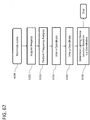
- FIG. 12 is a description of the content database 903 and content log 1201 information containing static content 1202, user-based content 1203, and dynamic content 1204.
- Content log 1201 is a representation of the file structure that contains the information found inside the content database 903.
- Static content 1202 refers to unchanging information that is associated with the specific area 801. This may refer to the previous example in which a facility manger loads specific content into the content 903 database before a user enters the specific area 801. This type of information may take the form of but is not limited to audio recordings, streaming or stored video files, images, or links to local or remote websites.
- User-based content 1203 refers to content that is dependent on user criteria.
- the content may depend on, but is not limited to, user age, sex, preference, habits, etc. For instance, a male user might receive different advertisements and promotions than a female would. Additionally, age and past purchase habits could also be used to distinguish which is the correct piece of content to be presented to the user.
- Dynamic content 1204 refers to content which changes with varying frequency.
- the content may change dependent on a temporal bases, daily, weekly, monthly, etc. For instance, seasonal marketing and content could be automatically presented to the user dependent on the month of the year, or content in the form of morning, evening, or nightly specials could be presented numerous times throughout the individual day.
- point of purchase 1205 information may be delivered as well. This could be implemented by using the received ID code 701 to a secure connection that establishes and completes a transaction linked to a user's selected payment method. Additionally, a standalone point of purchase feature could be implemented by simply linking ID codes 701 directly to merchandise or services.
- Dwell time 1303 refers to the time spent in each particular location inside a specific area 801. Separate records are maintained for individual users, and the dwell times are aggregated and sorted in the dwell time file. Path taken 1304 refers to the physical path taken by a user in each specific area 801.
- the store owner Prior to the customer entering the store, the store owner has already calibrated and preloaded the database 802 with the unique LED light sources 101, map 902 information pertaining to the store floor plan 1102, user-provided 1104 product locations, and content 903 in the form of multimedia and local deals in the form of promotions that may only be activated by visiting that particular section of the store.
- the customer is walking around the store looking to find particular items on her shopping list that she has already digitally loaded onto her mobile device 103.
- the customer is prompted by her mobile device 103 that one of the items on her list has changed locations and an image of the store layout is displayed with a flashing icon indicating where her desired product has moved.
- the mobile phone may guide her to the new product.
- an informational video is prompted on her screen detailing the most popular recipe incorporating that product and how it is prepared.
- the customer receives a discount promotion for taking the time to seek out the new location of the product.
- the store owner now gains value from learning about the shopping experiences of the customer. This comes in the form of aggregated data that is captured and stored in the analytics 904 section of his store's database 802. This example is one of many applications that may be enabled with an accurate indoor light-based positioning system.
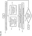
- FIG. 14 is a process describing the act of receiving location and content information through visible light.
- User places mobile device under light 1401 corresponds to the act of physically placing a camera equipped mobile device 103 underneath an enabled LED light source 101.
- the user stands approximately underneath or adjacent the LED light source 101, and the mobile device has the LED light source 101 in view of the camera lens.
- sample image sensor 1402 refers to the act of turning on and reading data from the embedded image sensor in the mobile device 103.
- Receive ID? 1403 is a decision block which either moves forward if a location ID is received, or returns to sample the image sensor 1402. Get location data corresponding to ID from server 1404 occurs once a location ID has been received.
- the mobile device queries the server asking for location data 702 relevant to the ID code. This describes the process of a user obtaining an ID code 701 from a non-networked LED light source 101, and using the unique identifier to look up additional information from either the server 703 or a locally stored source.
- Content? 1405 is another decision block which determines if there is location-based content associated with the received ID code. If content is available the process continues on to the last block 1406 where the content is queried; if not, the process ends.
- the get content data corresponding to ID from server 1405 refers to the act of retrieving content data associated with a known location from either a server 703 or local source.
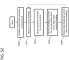
- FIG. 15 is a process describing the act of turning on the application background services and determining when to sample the image sensor.
- Initiate background service 1 1501 is the primary background running service on the mobile device. This service is tasked with initiating a function that can communicate wirelessly to determine if the mobile device is close to an enabled area.
- the wireless communication includes radio frequency communication techniques such as global position system (GPS), cellular communication (e.g., LTE, CDMA, UMTS, GSM), or WiFi communications.
- GPS global position system
- cellular communication e.g., LTE, CDMA, UMTS, GSM
- WiFi communications e.g., WiFi communications.
- Determine position 1502 is the function that periodically samples the wireless communication signal and based on distance parameters decides whether or not the mobile device is close enough to an area to move forward to the next service.
- Light positioning enabled? 1503 is a decision block that moves forward if the mobile device is close to an enabled location, or repeats the previous function if not.
- Initiate background service 2 1504 is activated once the mobile device enters an enabled area. The service is tasked with initiating the functions that receive location information via the modulated light.
- Sample ambient light sensor 1505 is the first function of the previous service that samples the ambient light sensor data as soon as the sensor detects a change. The function of this task is to determine if the sensor has gone from dark to light, if the user takes the device out of a pocket or enclosure, or from light to dark, the user has placed the device inside of a pocket or enclosure. As an alternative to sampling the light sensor, the algorithm could also look for a change in the accelerometer reading. This may correspond to the user taking the phone out of their pocket. Detect change? 1506 is the decision block that moves forward if the ambient light sensor has gone from dark to light, meaning that the mobile device is potentially in view of surrounding modulated light.
- Sample alternative sources 1603 refers to the act of leveraging existing alternative positioning technologies such as WiFi, Bluetooth, ultrasound, inertial navigation, or employing an existing service using one or more of any available services.
- Record internal sensor data 1606 is a task which records the current accelerometer data for a period of time before returning to the Sample image sensor 1402 block. This task is performed so that location information is constantly being collected even when modulated light is not being detected. This allows the mobile device and/or server to keep track of the mobile device's position.
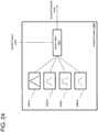
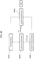
- FIG 17 is a system diagram describing how a client device 1704 interacts with a light-based positioning system 1709.
- Network 601 is a generic local or remote network used to connect mobile devices 103 contained in locations A 1701, B 1702, and C 1703 with the light-based positioning service 1709.
- Each location contains multiple LED light sources 101, each of which broadcast unique identification codes 701.
- a mobile device may use the database service application 1710 which contains multiple privilege levels for different levels of access.
- the client privilege level determines read/write permissions to each of these databases.
- These levels include users 1705 which refer to general front end system users, administrators 1706 which are usually IT or operations management level within an installation, developers 1707 which have access to the application programming interfaces of the system for use in custom application development, and root 1708 level which contains master control over the users and access to everything contained in the system and databases.
- the client uses a password authorized login screen to access the respective permission status.
- Clients with administrator permissions have read/write access to light IDs 901, read access to maps 902, read/write access to content 903, and read access to analytics 904.
- Clients with developer permissions 1707 have read access to light IDs, read access to maps 902, read/write access to content 903, and read access to analytics 904.
- a client with root permissions 1708 has read/write access to databases 901-904.
- FIG. 17 describes the top-down approach to an exemplary implementation of a light-based positioning system.
- known locations of installed non-network standalone LED light sources 101 are used to accurately identify the relative position of mobile devices 103.
- the background processes running on the mobile device 103 have been described in FIGS. 14 , 15 , and 16 .
- the mobile device uses this information to query a database 802 for additional information.
- This information may come in many forms, and is used to create a more personalized experience for the user. As initially mentioned, this local experience is used for location-aware mobile computing, and augmented reality applications.
- location-based analytics applications may be enabled from the aggregated data and traffic running through the server 703.
- the use of light-based positioning capabilities provide a number of benefits.
- the positioning information obtained by using light sources is highly precise compared to alternative techniques for positioning information.
- the accuracy of a light-based positioning system may be down to a few centimeters in three dimensions in some embodiments.
- This positioning ability enables a number of useful services to be provided.
- additional mobile device information may be used in combination with the positioning information.
- accelerometer position information may be used in conjunction with light source based position to offer augmented reality or location aware content that relevant to the device's position.
- the relevant content may be displayed to augment what is being displayed on the mobile device or the display can provide relevant information.
- Applications on the mobile device may also be launched when the mobile device enters certain areas or based on a combination of criteria and position information. The applications may be used to provide additional information to the user of the mobile device.
- the light-based positioning systems and techniques may also be used to manage and run a business.
- the light-based positioning may help keep track of inventory and to make changes to related databases of information.
- the light-positioning system may direct a person to where a particular item is located by giving directions and visual aids.
- the light positioning may even provide positioning information to direct the person to the correct shelf the item is currently residing on. If the person removes the item, the mobile device may update the inventory databases to reflect the change.
- the same function may be implemented in a store environment as merchandise locations are changed or updated. This information may then be used in providing content to a user.
- the updated location may be used to locate the item or direct the shopper to an online website to purchase an out-of-stock item.
- the mobile device using the light-based positioning technique in conjunction with a wireless connection and other information may be used to provide non-intrusive data collection on customers. The data collection of how customers move through a store and where they spend time may be used to improve layout of stores and displays of merchandise.
- the light-based positioning systems are also easy and low-cost to set up compared to other location-positioning systems. Since each light source operates autonomously, a building owner only needs to swap out existing light sources for those that provide light-based information to a camera-enabled device.
- the light sources are non-networked independent beacons that broadcast identification codes configured when manufactured. This allows the light sources to be manufactured at a lower cost compared to networked light sources. Further, the non-networked independent beacon light sources in the light-based positioning system may be easier for building owners to install.
- the light-based positioning system may also include optimizations in some embodiments. For example, location information obtained from either the identification code or from alternative techniques can be used to reduce latency in determining position information. This optimization may work through geo-fencing by constraining the search area to find information regarding the captured light sources more quickly. This can reduce the overall delay experienced by a user from the time the mobile device captures the light sources to when relevant position information is provide to the mobile device and/or relevant content is provided to the mobile device.
- beacon-based light-positioning systems are managing the additional power consumption of communication-enabled lighting devices in comparison to that of non-communicating devices.
- Lighting sources 101 in general, regardless of form factor or technology, are differentiated in part by their power consumption; generally, the less the better. Accordingly, higher energy efficiency is one of the core economic forces driving adoption of Light-Emitting-Diodes (LEDs).
- LEDs Light-Emitting-Diodes
- the power requirements tend to increase depending on the modulation scheme since energy must be divided between the carrier wave and the modulation wave.
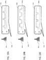
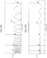
- FIGS. 18A-C represent several digitally modulated light sources 101a-c with varying duty cycles; a low duty cycle 1801, a medium duty cycle 1802, and a high duty cycle 1803.
- a duty cycle is a property of a digital signal that represents the proportion of time the signal spends in an active, or "on,” state as opposed to an inactive, or "off,” state.
- a light source with a low duty cycle 1801 is inactive for a high proportion of time.
- a light source with a medium duty cycle 1802 is inactive for about the same proportion of time that it is active.
- a light source with a high duty cycle 1803 is active for a high proportion of time.
- the duty cycle of a light source affects the luminosity of the light source.
- a light source having a higher duty cycle generally provides more luminosity than that same light source with a lower duty cycle because it is on for a higher proportion of time.
- Duty cycle is one aspect of a modulation scheme. Other aspects include pulse shape, frequency of pulses, and an offset level (e.g., a DC bias).
- DPR modulated light sources 101 rely on frequency modulation, they are able to circumvent the limitations of traditional AM based approaches. Note that frequency modulation in this context does not refer to modifying the frequency of the carrier (which is the light signal), but instead to modifying the frequency of a periodic waveform driving the light source.
- One popular technique for dimming LED light sources 101 is pulse-width modulation (PWM), which controls the average power delivered to the light source by varying the duty cycle of a pulse. In a DPR modulation system utilizing PWM, a DPR modulator would control the frequency of the pulses, with the duty cycle determined by the dimming requirements on the light source 101.
- PWM pulse-width modulation
- a DPR-modulated light source having a DPR modulation frequency
- the data may include information in the form of an identifier that distinguishes a light source from other nearby DPR-modulated light sources.
- this identifier is a periodic tone that the light source randomly selects to identify itself.
- a periodic tone may be a signal that repeats with a given frequency.
- a light source may receive such an identifier from an external source.
- the modulation frequency (f) of the transmitter and the sampling time for the image sensor (T s ) of the receiver are first defined.
- the duty cycle parameters (T off ) and (T on ) that correspond to the on and off times of the light source are defined.
- T s is an important parameter because the image sensor sampling time defines a minimum amount of modulation time required to produce the banding effects which allow for the frequency detection required for DPR demodulation.
- the required modulation time may refer to either the T on portion 1804 or the T off portion 1805 of the signal; however, to maximize the brightness of the light source, T off is used as the limiting variable (if solving for the minimum duty cycle, T on may be used).
- T s of the receiving device is less than twice T off of the light source, residual banding on the image sensor will typically not take place; therefore, the signal cannot be extracted.
- T s should be greater than twice the value of T off (T s > 2 ⁇ T off ).
- the modulation frequency may be defined from the transmitter side and may be completely independent of the sampling time T s .
- T s is a property of the receiver, which is defined by the image sensor manufacturer and is likely not designed for optimal DPR demodulation properties.
- T s varies depending on the specific image sensor, and may be expected to change as more advanced image sensors are developed. Therefore, it is important to optimize such that a broad range of both modulation and sampling frequencies may be used.
- equations and variables for the calculation of the maximum duty cycle are described for a variety of test cases.
- T off in terms of duty cycle and modulation frequency
- D 1 - T off /(T on + T off ).
- f 1/(T on + T off ).
- T off which was previously defined as a value less than twice T s , may then be used to define the maximum duty cycle for any given modulation used in DPR demodulation.
- the modulation frequency range was chosen to start at 300 Hz, which is above the range which the human eye can see.
- the modulation frequency range may range from 60 Hz to 5000 Hz.
- the image sensor sampling frequencies may range from as low as 1 KHz to as high as 1 MHz.
- the input power may be increased such that the resulting average power of the communicating light source 101 is identical to the non-communicating light source 101.
- the average power of the two light sources will be the same, yielding a perceivably identical luminous output. Take for instance LED source “A” that is powered by 6 watts and modulated where 50% of the time it is "on”, and the remaining 50% “off”, effectively resulting in a 3-watt average power.
- this light source 101 may double the input power from 6 watts to 12 watts. While the input power of "A” was increased, the average power is halved to equal 6 watts; therefore, sources “A” and “B” appear to be identical to the human eye in terms of brightness.
- LED lighting devices it is important to stay within the manufacturer-specified voltage and, more importantly, current, otherwise efficiency drastically falls with increased supply current. This unwanted effect is known as LED "droop,” and generally refers to decreased luminous output for any given individual LED (assuming one or more LEDs per lighting source 101) due to the additional thermal heating resulting from the increased current.
- LED "droop” the input power to LED source "A” was doubled while the input power to "B” was left unchanged. Assuming that each source was supplied by a constant 12 volts, this means that the input current to source “A” had to have doubled in order to achieve the required 12 watts of power consumption. This equates to a 50% increase in current, when moving from 0.5 amperes to 1 ampere, and may only be performed if within the manufacturers' tolerable input current range for the LEDs.
- modulation schemes 1901, 1902, and 1903 depict varying duty cycles where a DC bias 1904 has been added which correspond to the modulated light sources 101a-101c. Modulation schemes where the light source 101 does not turn all the way “off” are important when considering light source 101 brightness, efficiency, lifetime, and the signal to noise ratio (SNR) of the communications channel.
- the DC bias 1904 during modulation reduces the peak power required to drive the light source for a given brightness. A reduction in peak power will reduce the negative impact of overdriving the lighting source, which is known to cause efficiency losses known as "droop" for LEDs, in addition to decreasing light source 101 lifetimes.
- D the duty cycle
- P on P off are the respective on/off powers.
- the impact on light source 101 brightness is that increasing the "off" power will increase the total power. This reduces the required peak power delivered to the lighting source, because the power transferred during the "off” period can make up the difference.
- a 10% increase in the "off” period power translates to a 10% decrease in the "on” period power.
- I av ⁇ V D ⁇ I on ⁇ V+(1 - D) ⁇ I off ⁇ V.
- I av D ⁇ I on + (1 - D) ⁇ I off .
- a constant current may be applied with differing voltages to achieve a similar effect.
- Another major requirement for DPR modulation is to interface with existing light dimmers.
- light source 101 dimmers employed on the commercial market.
- One popular dimming technique is triac dimming.
- a triac dimmer a variable resistor switch is used to control the amount of power delivered to the light source 101 over the AC line.
- LED light sources 101 it is necessary to put a special driver between the triac dimming circuit and the LED source. This is because LEDs are current-driven devices, and thus require an AC/DC converter to transform AC from the power lines to a DC current for driving the LEDs.
- FIG. 20 demonstrates a system by which a DPR modulator may interface with existing lighting control circuits.
- a dimmer controller 2002 sends a dimmer signal 2003 to a dimmable LED driver 2006.
- the dimmable LED driver 2006 converts the dimmer signal to a pulse width modulated signal used for driving the light output 2007 of the source 2001.
- the configuration of the system diagram shows the dimmer signal 2003 going to both the DPR modulator 2004 and the LED driver 2006; however, this does not always need to happen.
- the LED driver 2006 may contain a "master override" input that is designed to supersede any dimmer signal 2003 input. In this case, the dimmer signal 2003 still goes to the LED driver 2006, but is ignored. In other cases where there is not an override input, the dimming signal only goes to the DPR modulator.
- DPR modulator 2004 is responsible for sending DPR signals 2005 to the LED driver 2006 that controls the light output 2007.
- DPR modulator 2004 controls the frequency of the PWM signal and selects the desired value.
- the width of pulses in signals 1801-1803 are determined based on dimmer signal 2003, which indicates the desired light source 2001 brightness level. Note that the dimmer controller 2002 is not contained within the light source 2001, and may output a variety of dimmer signals 2003 (triac, or a proprietary method).
- the DPR modulator 2004 is responsible for interpreting these different signals and appropriately outputting a DPR signal 2005 that corresponds to the desired brightness level of the inputted dimmer signal 2003.
- the DPR modulator 2004 interfaces directly with the LED driver.
- the DPR modulator 2004 may also be contained inside the LED driver 2006 as part of an integrated solution instead of as a separate component.
- FIG. 21 contains a high level overview of a DPR modulator 2004.
- Data 2101 is first sent to DPR tone generator 2102.
- Data 2101 may contain information from any source.
- data may include the identifier for the light.
- DPR tone generator 2102 converts the data 2101 into a sequence of DPR tones.
- a DPR tone is a periodic digital signal that oscillates between active and inactive states with a particular frequency. This process is described further in FIG. 22 . Depending on the requirements of the data transmission channel, this could either be a single tone (suitable for a beacon based positioning system using light identifiers), or a sequence of tones (if higher data rates are desired by the end user).
- the DPR Tone(s) 2203 are then sent to the waveform generator 2103, which is responsible for generating the DPR signal 2005 for driving the LEDs.
- Waveform generator 2103 receives a dimmer signal 2003 input from a dimmer controller 2002, which controls the brightness of the light source.
- dimmer controller 2002 would control the duty cycle of square wave 1802, while DPR Tone(s) 2203 would control the frequency of the square wave.
- the result is an output DPR signal 2005, which is then sent to the LED driver 2006.
- FIG. 22 contains a breakdown of DPR Tone Generator 2102. This module is responsible for taking a piece of data and converting it to a sequence of DPR tones.
- a DPR tone determines the frequency at which a waveform, such as the square waves from FIG. 18 , is sent.
- the range of possible tones, defined here in as T o through T n is determined by both the sampling time, T s , of the image sensor (as discussed in paragraph 0006), and the frequency response of the light source 101.
- Encoder 2201 is a standard base converter - it takes a piece of data in binary and converts it into a corresponding DPR tone.
- a typical range for tones created by DPR Tone Generator 2102 is 300Hz-2000Hz, in steps of 10Hz, allowing for 170 distinct DPR tones.
- the step size between tones is selected to reduce noise, and depending on the requirements could be much higher or lower than 10 Hz.
- that data 2101 may contain an identifier of value 10 for light source 101. This identifier is passed to Tone(s) Generator 2102, which generates (or selects from memory) a sequence of tones. Note that the length of a DPR tone sequence could be as low as 1 (in the case of a single tone used in a beacon-based positioning system). In this example, an identifier of 10 would map to a DPR tone of 400Hz.
- DPR Tone Generator 2102 could either store the identifier in memory beforehand, using pre-computed mappings of data to tone sequences, or alternatively it could compute this on the fly.
- the exact method of generating the sequence of tones may be driven by the resources available on the light source 101. Once one of the possible tones sequences 2202 is created, it is sent to Waveform Generator 2103.
- FIG. 23 contains the breakdown of Waveform Generator system 2103, which combines a tone sequence 2202 with a waveform from symbol creator 2303 and dimmer signal 2003 to create a DPR signal 2005 for driving light source 101.
- the resulting waveform will be periodic, with a frequency defined by the sequence of tones, a symbol created based on the list of possible symbols in symbol creator 2303, and an average output (brightness) determined by the dimmer signal 2003.
- This desired brightness could either be hard-coded on the module, or provided as an external input through a dimming control module.
- the choice of a symbol is determined within Symbol Selector 2301, which generates a control line 2302 for selecting a symbol from symbol mux 2402.
- FIG. 24 contains the breakdown of Symbol Creator 2303, which holds possible symbols 2401a-2401d. These could include a saw tooth wave 2401a, sine wave 2401b, square wave 2401c, and square wave with a DC offset 2401d, or any other periodic symbol. Symbol creator then takes in a selected symbol 2402, and modifies it such that a desired brightness 2106 is achieved. In the case of a square wave symbol 2401c, dimmer signal 2003 would modify the duty cycle of the square wave. The resulting waveform is then sent to output signal 2005 for driving the light source.
- the goal of the output waveform 2105 which drives light source 101, is to illuminate a scene in such a way that the DPR modulated signal may be picked up on any standard mobile device 103.
- Reducing flicker on video which is under illumination from fluorescent lamps is a well-known problem.
- the flicker is caused by periodic voltage fluctuations on the AC line powering the lamp.
- the luminance level changes at 100 Hz.
- This causes alternating white/dark bands to appear in video recorded with CMOS imagers.
- the bands are a result of the rolling shutter mechanism on CMOS imagers, which partially expose different areas of the image at different points in time.
- the lines on the image may occur on both, one, or on multiple frames, and may appear to move in time.
- DPR demodulation instead of removing flicker, exploits the rolling shutter effects of CMOS cameras as a means of transmitting data.
- a CMOS device with a rolling shutter captures an image frame by sequentially capturing portions of the frame on a rolling, or time-separated, basis. These portions may be vertical or horizontal lines or "stripes" of the image that are captured at successive time intervals. Because not every stripe is captured in the same time interval, the light sources illuminating the image may be in different states at each of these time intervals. Accordingly, a light source may produce stripes in a captured frame if it is illuminated in some time intervals and not illuminated in other time intervals. Light sources that broadcast digital pulse recognition signals may produce patterns of stripes.
- image processing techniques may be used to deduce the illumination frequency based on the width of the stripes. For example, consider a room containing five light sources 101, each broadcasting at 500 Hz, 600 Hz, 700 Hz, 800 Hz, and 900 Hz, respectively. Each distinct frequency, otherwise known as a DPR tone, may be used to identify the light source 101.
- a mobile device receiver within view of the transmitting lights can detect the DPR tones, correlate an identifier associated with the tone, and then use a lookup table to determine the location of the device based on the location associated with the identifier(s).
- FIG. 25 is a continuous time representation 2501 of how an individual row on a rolling shutter image sensor is sampled.
- the exposure time interval 2502 represents the period over which light accumulates on the photo sensor. If the exposure time is much lower than the period of the DPR modulated signal, the light and dark bands will be clearly defined. If the exposure time is longer, the light and dark bands will lose their definition.
- FIG. 26 contains a continuous time example 2601 of a DPR modulated light signal.
- the signal is a square wave with a 50% duty cycle being driven at a DPR tone of 300Hz.
- the relationship between the DPR illumination period 2602 and the exposure time 2502 determines how well defined the bands are on the received image.
- FIG. 27 is the continuous time sampled image 2701, created by convolving an individual row sampling function 2501 with a DPR modulated signal 2601.
- the alternating periods of high brightness 2702 and low brightness 2803 are caused by the DPR modulation frequency, and appear as alternating white/dark bands on the received image.
- FIG. 28 is a representation of a discrete time-domain signal model 2801 for representing how a rolling shutter on an image sensor samples the incoming light pulses 2601.
- the rolling shutter is modeled as an impulse train, containing a sequence of the Dirac Delta functions (otherwise known as a Dirac comb). Each impulse is separated by an interval, T, which corresponds to the speed of the rolling shutter commonly found in most CMOS image sensors.
- the interval T varies from device to device which causes the bands on scenes illuminated by DPR modulated signals to vary in size.
- the mobile device 103 preferably accounts for hardware-dependent factors (e.g., rolling shutter speed) to properly determine the DPR tone.
- FIG. 29 contains a discrete time representation 2901 of the rolling shutter sampling functionality over multiple frames.
- DPR demodulation on current imaging technology is capable of much higher data rates than modulation schemes that sample on a per-frame basis.
- the sensor would capture 480 samples per frame (represented as 480 consecutive delta functions in sensor model 2801).
- a demodulation scheme using a global shutter would only be capable of taking one sample per frame. This is a key advantage for indoor positioning using beacon-based broadcasting schemes because the time-to-first-fix is orders of magnitude faster than competing technology, which may take several seconds to receive a signal. For example, consider a typical mobile device 103 camera which samples at 30 frames per second (FPS).
- FPS frames per second
- time-to-first-fix may be achieved with as little as a single frame, or 1/30 of a second, versus 1 second for a demodulation scheme that samples on a per-frame basis. This compares to a time-to-first-fix of up to 65 seconds for GPS, 30 seconds for assisted GPS, and 5-10 seconds for WiFi positioning.
- DPR demodulation may be performed on the mobile device itself, versus the server-side processing required for WiFi fingerprinting algorithms.
- client-side processing provides a major advantage.
- image sensors will have much higher frame rates.
- DPR demodulation may be adjusted to sample on a per-frame basis, instead of a rolling shutter basis.
- the key principle is that the demodulator may be adjusted in software, allowing future mobile devices to tune their receiving characteristics to receive DPR signals.
- the software adjustments that need to be applied are the subject of the following sections.
- the device In order to prepare a mobile device 103 to receive the modulated DPR signals 2105, the device is first configured. This is to counteract the flicker-mitigation algorithms typically applied in mobile device image sensors.
- FIG. 30 describes the method by which mobile device 103 is configured to receive DPR modulated signals.
- the initialize sensors 3001 function initializes and activates the available sensors capable of receiving data. For typical modern mobile devices these would include both the front- and rear-facing cameras.
- a "front-facing" camera or other sensor of a mobile device is one that is mounted on the same side of the device as its display and is therefore likely to face toward a user.
- the rear-facing camera or another rear-facing is used because it is more likely to have a view of the user's surroundings that is relatively unoccluded by the user's own body and thus to record light cast directly by local light sources.
- Determine sensors to modify 3002 then decides which sensors need to be modified. A number of possible factors determine whether or not a particular sensor should be initialized then modified, including power consumption, accuracy, time since last reading, environmental conditions, required location accuracy, and battery state.
- Modify sensors 3003 then passes a list of the appropriate sensors which need to be modified to a function which has additional information about the mobile device 103 and adjusts the demodulation scheme for device specific limitations 3004.
- possible sensor parameters to modify include exposure, focus, saturation, white balance, zoom, contrast, brightness, gain, sharpness, ISO, resolution, image quality, scene selection, and metering mode.
- sensor parameters such as exposure, white-balance, and focus are locked to prevent further adjustments.
- Lock parameter 3103 then locks this exposure time to prevent the auto-adjustment feature of the camera from overriding the manual setting.
- adjust for hardware dependent parameters 3104 accesses a lookup table and adjusts the demodulation algorithm based on hardware and software differences. For the case of an image sensor, one example of this is changing the sampling time based on the rolling shutter speed of the device. This rolling shutter speed may either be loaded from a lookup table beforehand (using predetermined values) or measured on the fly. Each device only needs to measure its rolling shutter speed once per image sensor. Once parameters set? 3105 is satisfied the algorithm ends; otherwise, it returns to identify regions of interest 3101.
- the method of exploiting the metering area on a mobile device 103 may be used to optimize many of the required parameters in addition to the exposure, including white balance, contrast, saturation, ISO, gain, zoom, contrast, brightness, sharpness, resolution, image quality, and scene selection. Furthermore, these parameters could already be known beforehand, as each mobile device 103 will have its own "device profile" containing the optimal camera settings. This profile could be loaded client side on the device, or sent over a server. Note that although the method of using the metering area to control the exposure may improve the performance of DPR demodulation, it is not strictly necessary. Simply locking the exposure 3103 is often sufficient to prevent the automatic camera adjustments from filtering out the DPR signals.
- FIG. 32 describes a process for decoding the information contained inside a DPR modulated signal. Identify regions 3201 is used to separate different regions on the image illuminated by DPR signals. At the base level, the region of interest is the entire image. However, when one or more light sources 101 are present, there exists an opportunity to receive multiple DPR signals simultaneously. In this scenario, the sensor effectively acts as a multiple antenna receiver.
- Such multiple antenna systems more generally referred to as multiple-input multiple-output (MIMO), are widely used in the wireless networking space. This is an example of spatial multiplexing, where wireless channels are allocated in space as opposed to time or frequency.
- MIMO multiple-input multiple-output
- MIMO for DPR demodulation in a beacon-based light-positioning system
- a mobile phone user receives DPR modulated signals on a photodiode array (such as an image sensor, or any imaging technology that contains multiple spatially separated sensors)
- the DPR signals will each appear at different locations on the sensor.
- Each region 3201 of the image may then be processed independently, in the same way that each mobile phone user in a cell network only connects to the cell they are closest to.
- detect frequency content 3202 identifies the presence of DPR tones from the sensor data. Described here are multiple methods for extracting the frequency content from a DPR signal. One possibility is to use line-detection algorithms to identify the pixel width of the stripes, which directly corresponds to the transmitted frequency. This stripe width is then used to access a lookup table that associates width and transmitted frequency and determines the transmitted tones. Possible methods for detecting lines include Canny edge detection, Hough Transforms, Sobel operators, differentials, Prewitt operators, and Roberts Cross detectors, all of which are well developed algorithms, known to those of skill in the art.
- Adjust for dependent parameters 3004 modifies the appropriate camera sensors for optimal DPR demodulation. In the case of line detection, this corresponds to a linear adjustment for the line width lookup table.
- Determine tones 3203 uses the adjusted line width to determine the DPR tone sent. This process is performed for each region on the image, until there are no more regions 3204 remaining. A data structure containing all the regions, with their associated identifiers, is then returned 3205.
- FIG. 33 An additional method for performing DPR demodulation is described in FIG. 33 .
- One or more light sources 101 illuminates a scene 3301.
- the image sensor on mobile device 103 acquires a sequence of images 3302
- the brightness of any given pixel depends on both the details of the scene as well as the illumination.
- scene refers to the area within view of the camera.
- the scene dependence means that pixels in the same row of the image will not all have the same brightness, and the relative brightness of different image rows is not solely dependent on the modulated illumination 3301. If one were to take the Fourier transform of such an image, both the frequency content of the illumination, as well as the frequency content of the underlying scene, will be present.
- the illumination signal will be in a different part of its period at the beginning of each frame, and the light and dark bands will appear to be shifted between video frames (i.e. the bands will appear to move up or down across the scene while the video is played).
- this algorithm is described with the use of a video sequence, other embodiments may perform background subtraction using still images.
- the bands move between video frames, the average effect of the bands on any individual pixel value will be the same (assuming that in a long enough video each pixel is equally likely to be in a light or dark band in any given frame). If all the video frames are averaged, the effects of the bands (due to the illumination modulation) will be reduced to a constant value applied to each pixel location. If the video is of a motionless scene, this means that averaging the video frames will remove the effect of the bands and reveal only the underlying scene (plus a constant value due to the averaged bands). This underlying scene (the background) may be subtracted from each frame of the video to remove the effects of the scene and leave only the effects of illumination modulation 3301.
- FIG. 35 describes a technique for dealing with motion between frames, which is a likely scenario when demodulating DPR signals on mobile device 103.
- Motion compensation 3501 is necessary to best determine the underlying scene. By determining the motion between video frames (for example, shifting or rotation of the whole scene due to camera movement), each video frame may be shifted or transformed such that it overlies the previous frame as much as possible. After performing these compensatory transforms on each frame in motion compensation 3501, the video frames are averaged 3403 to get the scene background 3404. Phase correlation is one possible method of estimating global (i.e., the whole scene moves in the same way, as in the case of camera motion while recording video) translational motion between frames.
- the 2D Fourier transform of a shifted image will be the same as that of the original image, except that a phase shift will be introduced at each point. Normalizing the magnitude of the 2D Fourier transform and taking the inverse transform yields a 2D image with a peak offset from the center of the image. The offset of this peak is the same as the shift of the shifted image.
- additional methods for motion compensation 3501 include Kernel Density Estimators, Mean-shift based estimation, and Eigenbackgrounds.
- FIG. 36 contains a sample image 3601 of a surface illuminated by a light source undergoing DPR modulation. The image is being recorded from a mobile device using a rolling shutter CMOS camera. The stripes 3602 on the image are caused by the rolling shutter sampling function, which is modeled in by the sequence of Dirac Combs 2801 in FIG. 28 .
- FIG. 37 shows the result 3701 of performing background subtraction on the raw image data from FIG. 36 .
- Background subtraction is used to extract the stripes from the raw image data.
- the result is an image of alternating black/white stripes that represents the discrete time-domain representation of the transmitted DPR signal.
- the stripes 3702 are much more pronounced than in the raw image data from FIG. 36 due to the improvement from background subtraction.
- Illumination modulation affects each row of a video frame identically, but imperfect background subtraction may lead to non-identical pixel values across image rows. Taking the Fourier transform of row values along different image columns, then, may produce different illumination signal frequency content results. Because the true illumination signal frequency content is the same for the entire image, a technique to reconcile these different results may be employed.
- One possible method is to assign the average pixel value for any given row to each pixel in that row. This method takes into account the information from each pixel in the row, but by yielding uniform row values gives a single illumination signal frequency content result when taking the Fourier transform of row values along an image column.
- FIG. 38 displays the results of applying row averaging 3801 to the background subtracted image 3701. The stripes 3802 are much more visible as a result of the row averaging, and they are also more consistent across rows.
- FIG. 39 shows the Fourier transform 3901 of the row averaged image 3801 from FIG. 38 .
- the peak frequency is used to identify the sequence of tones, and thus the transmitted identifier.
- FIG. 40 shows the Fourier transform 4001 from FIG. 39 after applying a high-pass filter.
- the DC component of the signal is removed, which allows a peak frequency detector to move to detection of the DPR tone frequency.
- FIG. 43 shows a high-pass filtered version 4301 of the 2-D FFT 4101.
- the dark area 4302 at DC demonstrates the result of the high-pass filter, which rejects the DC noise component.
- the higher frequency bands 4303 are still contained in the signal, allowing the demodulator to determine the peak frequency.
- a source of spectral noise in many digital images is the occurrence of regular brightness patterns. Such patterns are commonly produced by clothing designs, structural surfaces (e.g., brick walls, tile floors, ceiling tiles), carpeting designs, and other objects. Regular patterns tend to produce peaks in image FFTs and may thus confound the detection and identification of peaks corresponding to DPR signals in images as described in an illustrative fashion hereinabove. False positives (i.e., erroneous detections of DPR tones that are not present) and false negatives (i.e., failures to detect DPR tones that are present) may both be caused by spectral noise from visual patterns.
- Mobile devices typically focus their cameras automatically, but in some mobile devices it is possible to defocus the camera under software control (e.g., under the control of a mobile app). Such defocusing may be achieved simply by commanding focus at the nearest possible distance, on the presumption that the mobile device is unlikely to at closest-focus range from a wall, floor, or other patterned surface.
- a user may be instructed by software on their mobile device to point the device's camera at a surface at least 3-4 feet distant (e.g., to hold the unit approximately level at waist height so that the camera is pointing at the floor), increasing the likelihood that a closest-focus image will be defocused.
- defocusing employs an adaptive algorithm that seeks maximum defocus, e.g., by seeking a lens position that minimizes image contrast. This technique inverts the maximum-contrast autofocus method deployed in many digital imaging systems (which seeks a lens position that maximizes, rather than minimizes, image contrast).
- defocusing has the effect of low-pass filtering an image. That is, brightness changes that vary slowly across an image tend to be preserved with defocusing while brightness changes that vary rapidly tend to be attenuated.
- the precise equivalent filter characteristics of defocusing depend on distance of the camera from various surfaces in view, degree of defocusing, lens characteristics, and other factors, and so cannot be precisely defined or controlled for purposes of DPR-modulated light signal detection.
- a significant degree of low-pass filtering is usually obtainable by defocusing and is likely to aid FFT peak detection of DPR tones.
- Defocusing does not affect the DPR modulated light signal component of the defocused image (e.g., the stripes in FIG. 36 ), because the stripes produced on the image by the DPR signal are never part of the scene imaged by the camera lens; they are a purely digital artifact produced by the phase relationship of the rolling shutter exposure mechanism to the DPR modulated light signal. Defocusing therefore has no tendency to filter the DPR signal regardless of the DPR signal's frequency characteristics.
- digital filtering after image digitization may be performed by software (e.g., by an app running on the mobile device), according to various embodiments, to mitigate the effects of spectral noise from visual patterns.
- Digital low-pass filtering as will be clear to persons familiar with the art of digital signal processing, consists essentially of the performance of mathematical operations on numbers (e.g., pixel brightness values) which may represent samples of a signal (e.g., an optical image).
- numbers e.g., pixel brightness values
- samples of a signal e.g., an optical image
- digital filtering cannot substitute directly for the low-pass filtering effect of defocusing because digital filtering operates on the digital image itself, including any artifacts the digital image may contain (e.g., DPR striping).
- Digital filtering-especially simple filtering-therefore tends to affect the DPR component of an image along with any patterns arising from the optical image. Nevertheless, in various embodiments, digital filtering and other forms of digital signal processing (e.g., background subtraction) are contemplated, alternatively or additionally to defocusing, to enhance DPR signal detection in the presence of irrelevant image patterns.
- digital filtering and other forms of digital signal processing e.g., background subtraction
- the filtered digital image is subjected to FFT calculation and attempted peak frequency detection of any DPR tone frequency or frequencies present in the image as described hereinabove.
- FIG. 44A shows a portion of an illustrative image of a masonry wall in focus. Fine horizontal line structures 4402, 4404 are apparent in the image and recur periodically throughout the image.
- FIG. 44B shows the same portion of the illustrative image after deliberate optical focusing at the shortest possible range (i.e., "manual" defocusing). Broad, partially low-frequency bands of brightness and darkness 4406, 4408 are apparent but no fine image structures are visible such as the structures 4402, 4404 in FIG. 44A .
- the broad, horizontal brightness bands 4406, 4408 are a DPR tone frequency artifact and the object of DPR tone detection in processing this scene.
- the broad brightness bands 4406, 4408 may be seen in FIG. 44A as well, aligned by chance with alternate masonry rows.
- FIG. 45 shows FFTs of the full images from which the partial images of FIG. 44A and FIG 44B are taken.
- the FFT 4502 (dashed line) of the focused image features prominent peaks at around 650 Hz, 1450 Hz, and 2900 Hz.
- the peak at ⁇ 650 Hz corresponds to the DPR tone frequency pattern seen in FIG. 44B .
- the peaks at ⁇ 1450 Hz and ⁇ 2900 Hz arise from the fine line structures seen in FIG. 44A and may cause a DPR-seeking algorithm to produce false positives.
- the FFT 4500 (solid line) of the defocused image preserves the true DPR peak at ⁇ 650 Hz but reduces the spurious peak at ⁇ 1450 Hz and displays no spurious peak at ⁇ 2900 Hz.
- a DPR-seeking algorithm is therefore more likely to produce accurate results using the FFT 4500 of the defocused image than using the FFT 4502 of the focused image.
- the amplitudes of the focused FFT 4502 and the defocused FFT 4500 are indistinguishable on the scale of FIG. 45 ; only above ⁇ 1000 Hz is the filtering effect of defocusing apparent.
- the unit Hertz Hz, one cycle per second
- Hz is here used as a proxy unit for spatial frequency.
- a mobile device employing DPR modulated light signals to estimate its location may, in some states of operation, present the mobile device's user with a graphic interface that includes or consists essentially of a map.
- the map may be oriented on the display of the mobile device on the presumption that the user typically orients the device perpendicularly to the plane of the user's body.
- the map may also feature a "you are here" cursor that visually identifies the user's location (i.e., the location of the mobile device, presumed to be co-located with the user).
- the user interface may thus present the user with spatial map information about the layout of the user's surroundings (e.g., aisles, walls, doors, displays, kiosks), "you are here" locational information, and directional (heading) information.
- various embodiments employ a variety of methods to calculate and display an estimate of the user's position that is updated in real time as the mobile device opportunistically identifies DPR modulated signals from lights in various positions.
- software on the mobile device and/or on a back end or server employing data from a light-sensing device of the mobile device, cyclically seeks to identify light identification codes in ambient light. If no such codes are found, then the location of the mobile device cannot be estimated from information about the location of coded LED light sources. If the ID code of at least one LED light source is found, then the mobile device's position may be estimated.
- a first illustrative method of estimating the position of a mobile device by an app running on the device in a space containing DPR-modulated LED light sources is as follows.
- the app detects the presence of one or more light ID codes by analyzing data from a light-sensing device of the mobile device
- the location of the detected one or more LEDs may be obtained from a server as shown in FIG. 7 , FIG. 9 , and FIG. 10 .
- An initial estimate of device position may be determined from one or more light ID code detections according to various methods; most simply, an initial estimate may be given by the location of the first LED whose ID code is detected.
- a portion of a map which may also be obtained from a database on a server as shown in FIG.
- a raw value for the orientation of the device may be obtained from a magnetic compass built into the device and, as shall be made clear in figures and accompanying description hereinbelow, may be rectified or corrected using field-map information contained in the Maps database in the server ( FIG. 9 and FIG. 11 ).
- the map may be oriented on the display screen of the mobile device using raw or corrected orientation information, incorporating the assumption that the user typically holds the device perpendicularly to the plane of their body. The user thus is presented with an initial estimate of their position and orientation in the context of a spatial area map or portion thereof.
- the extent of the map portion displayed may be settable by the user: e.g., a larger or smaller portion of the area map surrounding the user's location may be displayed in response to user commands such as touchscreen pinch gestures.
- detections of one, two, or more light IDs may occur. Also, multiple detections of the IDs of one or more particular lights may occur. Even if the user is stationary, IDs of multiple lights may be detected, and if the user moves about sufficiently it is likely that they will move from detection range of one or more lights to within detection range of one or more other lights, and that ongoing ID detections by the mobile device will reflect such changes.
- a first method of calculating a time-varying estimate of device position using a time series of ID detections is designed to produce highly confident location estimates according to various embodiments of the invention.
- the Static Method considers whether p percent or more of IDs from a single light have been detected in the last n ID detections.
- the percent threshold parameter p and lookback time parameter n may be specified by the designers of the system that implements the Static Method, or may be settable by the device user or by software running on a different computer (e.g., the server). Parameter setting may also be performed by software in an adaptive (time-varying) manner.
- the current location estimate is set to the location of Light A.
- ID detections will shift, suddenly or gradually, from detections solely or primarily (i.e., more than p percent) of Light A to detections solely or primarily of Light B.
- the criteria for light-source identification i.e., p percent or more of the last n detections
- the location estimate will be updated to the location of Light B.
- the Static Method only supplies position estimates that correspond to the positions of individual light sources. For example, a Static Method position estimate cannot be intermediate between the locations of a Light A and a Light B, or at the center of a triangle whose vertices are Light A, Light B, and a Light C.
- Static Method An advantage of the Static Method is that it is likely to discard false positives. That is, the Static Method is very unlikely to estimate the location of the mobile device as being the location of any light source that is not the light source nearest to the device.
- the Static Method has at least four notable disadvantages, herein termed Lag, Snap, Bounce, and Failure to Estimate:
- a second method in various embodiments of calculating a time-varying estimate of device position using a time series of ID detections is designed to produce location estimates that are not susceptible to the drawbacks of the Static Method.
- the Statistical Method updates the position estimate every time a light source ID is detected.
- estimated positions are not restricted to the locations of LED light sources. Rather, the Statistical Method moves the position estimate fractionally or incrementally in the direction of each light source that is detected (or does not change the position estimate if the latest light source detected is co-located with the current position estimate).
- the size of each incremental movement may be weighted according to various criteria, e.g., by how long it has been since the previous successful ID detection (e.g., if it has been longer since the previous successful ID detection, then the position estimate is moved farther).
- a position estimate from the Statistical Method may stabilize (or approximately stabilize) near positions that are co-located with LED light sources, or that are between two LED light sources, or that are in the midst of three or more LED light sources.
- Max lag time is essentially the time that the Statistical Method will take to update completely from the position of a Light A to the position of a light B if the device is moved instantaneously from one to the other, where the distance between Light A and Light B is sufficient to prevent ID detections of each light at the location of the other. In the event of such a hypothetical jump, detections of Light A would suddenly cease and detections of Light B would suddenly begin.
- the initial position estimate i.e., the position of Light A
- the position estimate will shift M / K of the way toward the position of Light B upon each of the first K detections after the jump and thereafter will coincide with the position of Light B.
- the position estimate would make K shifts, moving M / K of the way from Light A to Light B on each shift and being coincident with the position of Light B after the K th shift, which occurs at the end of the max lag time of M seconds.
- the Statistical Method is so called because the position estimate it produces is in effect a moving average of weighted position vectors.
- the window may be finite in length, i.e., light ID detections older than some threshold specified in seconds or number of ID detections may be disregarded by the method.
- the Statistical Method has the drawback that false positives (incorrect ID detections) will be incorporated into the position estimate as they occur, potentially causing the position estimate to jitter or wander.
- the Statistical Method overcomes the four drawbacks of the Static Method described hereinabove:
- FIG. 46 is a high-level flow chart of an illustrative version of the Static Method for mobile device position estimation according to various embodiments of the invention.
- the method which is cyclic, may be entered at Acquire Camera Frames 4600 and exited from any part of the cycle by software interrupt (quitting the program).
- the mobile device acquires a digital photograph.
- a series of light-intensity readings may be obtained from a non-imaging light sensor of the mobile device.
- the photograph stored in the storage system of the device (storage 504 in FIG. 5 ), is subjected to signal processing (Signal Processing 4602) for ID detection in the CPU of the mobile device (CPU 502 of FIG.
- Signal processing in block 4602 may, for example, comprise background subtraction processing such as is shown and described in U.S. Patent No. 8,520,065 , the entire contents of which are incorporated herein by reference.
- the app software of the mobile device waits for yes/no confirmation or stabilization of light-source ID identification (Light Source ID Confirm? 4604) according to the criteria described hereinabove ( p percent of detections the last n detections). If no light ID is confirmed, the device returns to Acquire Camera Frames 4600. If fewer than n detections have occurred, additional detections will be sought at least until n detections have occurred, and thereafter until p percent of the latest n detections are of a single light source. If a light source ID is confirmed, the app updates its position estimate (Update Position Estimate 4606) to the position of the confirmed light source.
- Update Position Estimate 4606 Update Position Estimate 4606
- FIG. 47 is a high-level flow chart of an illustrative version of the Statistical Method for mobile device position estimation according to various embodiments of the invention.
- the method which is cyclic, may be entered at Acquire Camera Frames 4700 and exited from any part of the cycle by software interrupt (quitting the program).
- the mobile device acquires a digital photograph or series of readings may be obtained from a non-imaging light sensor.
- Signal Processing 4702 Signal Processing
- Remarks regarding Signal Processing 4602 in FIG. 46 apply equally to Signal Processing 4702. If a light source ID is identified, the app incrementally shifts its position estimate (Update Position Estimate 4704) in the direction of the detected light source as described hereinabove.
- the Statistical Method cycle of FIG. 47 in general entails a lower computational burden than does the Static Method cycle of FIG. 46 , as there is no step devoted to the examination of location confirmation criteria. That is, the Statistical Method tends to be more computationally efficient than the Static Method.
- FIG. 48 is an illustration of aspects of (a) an illustrative physical space (represented by a rectangle) in which a mobile device moves and which contains two ID-broadcasting light sources (column 1, Actual Position 4800) and (b) illustrative device displays (column 2, Output Display Static Method 4802; also column 3, Output Display Statistical Method 4804) that indicate the estimated position of the device according to either the Static Method or the Continuous Method.
- Actual position, Static Method output display of position estimate, and Statistical Method output display of position estimate are shown in top-down view for four consecutive times T1, T2, T3, and T4. The four times may not be evenly spaced.
- a mobile device physical position 4806 (indicated by an X) within a space 4808 is directly under a first light source 4810 (indicated by a dashed circle) broadcasting a distinct ID.
- a second light source 4812 is also present in the space 4408.
- device physical position 4806 and other repeated elements of FIG. 48 are explicitly labeled in FIG. 48 only for time T1.
- the physical device position 4806 is directly under LED light 4812. From T1 to T2, the user of the device has moved normally from a point under the first light source 4810 to a point under the second light source 4812.
- T2, T3, and T4 as depicted in the rest of column 1, Actual Position 4800, the device remains under the second light source 4812.
- Output Display Static Method 4802 the physical space 4808 is schematically depicted as it might be on a user's device display. That is, a representation 4820 of the physical space 4808, a representation 4814 of the device position estimate (indicated by a caret), and representations 4816, 4818 of the two light sources 4810, 4812 are all shown in the display.
- the position estimate 4814 is coincident with the symbol 4814 for the first LED light source 4810.
- the position indicator 4814 is still shown in Output Display Static Method 4802 as coincident with the first light symbol 4816. Even at time T3 the display has not changed from its state at T1.
- Output Display Statistical Method 4804 the same display symbols and conventions are used as in column 2, Output Display Static Method 4802.
- the position estimate 4814 is coincident with the symbol 4814 for the first LED light source 4810.
- the user is physically under the second light source 4812.
- the device 4806 began to detect the ID of the second light 4812; consequently, by time T3 the position indicator 4814 has been incrementally adjusted, perhaps repeatedly, in the direction of the second light symbol 4818. Similarly, by time T3 the position indicator 4814 has been further incrementally adjusted in the direction of the second light symbol 4818.
- the position indicator 4814 is coincident with the first second symbol 4818.
- the reduction of lag for the Statistical Method as compared to the Static Method is evident in the movement of the position indicator 4814 for times T2 and T3.
- the incremental movement of the Statistical Method position indicator for times T2, T3, and T4 indicates the typical, approximately smooth movement of position indicator for the Statistical Method, as opposed to the sudden jump of the position indicator from times T3 to T4 for the Static Method.
- the ability of the Statistical Method to estimate locations intermediate between light sources is apparent in the display of the position indicator 4814 for times T2 and T3.
- both the Statistical and Static Methods employ the relative frequency of detections of signals from given sources as a proxy for signal strength: that is, stronger signals are likely to be more frequently detected than relatively weak signals. Therefore, in various embodiments, other methods of employing relative signal strength or received signal strength indication (RSSI) of light sources as a basis for updating update the position estimates of the Statistical and Static Methods, or to produce such estimates by other methods, are contemplated and within the scope of the invention.
- RSSI received signal strength indication
- the relative heights of detected peaks may be used to directly estimate relative RSSI and thus the relative distances of distinct light sources.
- direct RSSI estimation may be used alternatively or additionally to frequency of ID detection (indirect RSSI estimation) to update device position estimates.
- FIG. 49 is a schematic, top-down, illustrative representation of the effect of local magnetic field anomalies on heading measurements made by a mobile device operating in the context of an indoor position location system (as in, e.g., FIG. 7 ).
- a mobile device 4900 e.g., smartphone
- barriers 4904, 4906 e.g., shelving rows
- Two ID-broadcasting LED light fixtures 4908, 4910 are located above the aisle.
- the horizontal component of the magnetic field 4912 of the Earth which is approximately uniform on the scale depicted and is here idealized as pointing to true North (indicated by a compass rose 4914), is represented as a set of parallel dashed arrows diagonally traversing the figure. Due to the presence of metallic masses, electrical machines, or other causes, the magnetic field at various points in the space depicted deviates from the Earth field 4912. For example, at the location of the first light 4908, the actual field 4916 (bold arrow) deviates by angle A1 from the Earth field, and at the location of the second light 4910, the actual field 4918 (bold arrow) deviates by angle A2 from the Earth field.
- Angles A1 and A2 are denoted by curved arrows bracketing each angle.
- the local field may vary in strength, as well as in direction, from the unperturbed Earth field, but variations in field strength will typically not affect heading measurements unless the field strength is reduced to a level not reliably detectable.
- the device 4900 is carried to the location of light 4908 and detects the broadcast ID of the light 4908.
- the device which is presumptively held in a significantly non-vertical position and perpendicular to the plane of the user's body, wirelessly queries a server for the location of light 4908; the server consults its database and tells the device what location estimate to use.
- the server also transfers map information to the device, which the device displays as a map for the benefit of its user, with "you are here" position indicator.
- the device takes a heading measurement using its internal compass and orients the map accordingly.
- the mobile device 4900 measures a field that deviates from the Earth field by angle A1. Therefore, if the map display is oriented using the raw compass reading measurement, it will be misaligned with the physical environment by angle A1, which will tend to degrade the performance of the indoor positioning system.
- the problem of local misalignment is addressed by the following technique.
- a commissioning process stocks the server Maps database with a layer of local field readings, herein termed the Deviation Table.
- the Deviation Table records the deviation of the local field from the unperturbed Earth field at some set of points covering part or all of the space served by the indoor positioning system (e.g., the locations of all ID-broadcasting LED lights in the space).
- FIG. 50A and FIG. 50B schematically depict the information thus recorded for two illustrative locations.
- a first point 5000 e.g., a location similar to that of light 4908 in FIG.
- the unperturbed Earth field 4912 (here idealized as pointing due North as indicated by compass rose 5002) is at angle ⁇ M with respect to an arbitrary reference axis 5004 and the deviant, actual field 5006 is at angle ⁇ D1 .
- the unperturbed Earth field 4912 is also at angle ⁇ M and the deviant, actual field 5010 is at angle ⁇ D2 .
- the local deviation angle ⁇ D1 is added to the angle ⁇ M of the unperturbed Earth field to produce a corrected heading; when a device is estimated to be at point 5008, the local deviation angle ⁇ D2 is added to the angle ⁇ M of the unperturbed Earth field to produce a corrected heading.
- Such addition may be performed either by the server, which transmits the corrected heading to the mobile device, or by software running on the mobile device itself.
- FIG. 51A and FIG. 51B depict aspects of the illustrative mobile device 4900 in two possible states of operation when at the position of first light 4908 in FIG. 49 .
- the screen 5100 of the device 4900 is displaying a map oriented according to a raw compass measurement.
- the device 5100 is aligned with the direction of motion 4902 in FIG. 49 (along the aisle), but the map (which includes depictions 5012 of aisle barriers and a "you are here" cursor 5014) is rotated erroneously by an angle of A1.
- the map displayed on the screen 5100 of the device 4900 is oriented accurately using a corrected heading.
- the estimated position of a mobile device in an indoor positioning system will not always coincide exactly with its physical position.
- heading corrections or deviations are recorded at a set of points corresponding to light-source locations.
- heading corrections for points not directly under light sources may be calculated by any of several well-known interpolation methods either prior to system operation or in real time, as intermediate location estimates occur. For example, at a given intermediate location, the measured deviation values for nearby light-source locations may be weighted by the inverse of their distances from the intermediate location (closer points, heavier weighting) and averaged to produce an estimate of the deviation at the intermediate location.
- a version of the Statistical Method for position estimation may be used to update orientation correction estimates.
- Interpolative estimations of deviation corrections may have two benefits. First, it may minimize the deviation error for mobile devices not physically located directly beneath light sources. Second, it may prevent sudden jumps or snaps of map orientation: as the "you are here" cursor moves more or less smoothly through the map space, the orientation of the map adjusts more or less smoothly as well. Orientation lag and snap may thus both be avoided or mitigated.
- FIG. 52 is a high-level flow chart of an illustrative method for applying deviation corrections to headings measured by a mobile device in an indoor positioning system according to various embodiments of the invention.
- the algorithm is cyclic and may be exited at any point by software interrupt (quitting the program). It is presumed in FIG. 52 that the device is already, by the time of Start, successfully detecting light-source IDs and that a position has been estimated for the device.
- the heading correction of the mobile device is initialized to zero (block 5200).
- a raw heading measurement is obtained from the device's internal compass (block 5202).
- the device queries the server for the correction value for the current location (block 5204).
- compass heading measurement (block 5202) and correction value querying of the server (block 5204) may occur concurrently, rather than sequentially as depicted in FIG. 52 .
- the map displayed to the user is rotated using the updated heading estimate to be consistent with the user's physical orientation.
- FIG. 53 is a high-level flow chart of an illustrative method for populating a Deviations Table. After starting, the algorithm is cyclic and may be exited at any point by software interrupt (quitting the program). It is presumed for the illustrative method of FIG. 53 that the space of interest may be mostly or wholly covered by a set of straight-line traverses (e.g., along aisles), but in various other embodiments curving paths may be accommodated. It is also presumed that a correctly oriented map of the space in question has already been created and stored in the server Maps database and that the true orientation of the map is known (e.g., by surveying techniques).
- the server's heading correction table (Deviation Table) for the space to be calibrated is initialized to zero (block 5300).
- an assistant carrying an appropriately equipped mobile device walks along a calibration path (e.g., from one side of a retail space to the other) holding the mobile device in a significantly non-vertical orientation and parallel to their direction of travel, and the device scans for light source IDs in the ambient light (block 5302). If a light source is not identified (branch point 5304), the assistant continues to walk and the mobile device continues to scan for light source IDs (return to block 5302).
- the device takes a heading measurement and compares it to the true heading of the device (block 1506).
- the true orientation (direction of travel) of the device may be inferred from the layout of the spatial map, whose true orientation is, as noted, already known: for example, if the assistant is walking down an Aisle Z, orienting the mobile device along their direction of travel, then the true orientation of the mobile device may be inferred as being the pre-measured orientation of Aisle Z.
- the device reports that deviation to the back end or server, which associates that deviation with that location in a stored table (the Deviation Table) (block 1508). If the assistant does not signal that they have reached the end of the calibration path (branch point 1510), then the assistant continues walking and the device continues to scan for light sources (return to block 5302). If the assistant does signal that they have reached the end of the calibration path (branch point 5310), then the server checks to see if its Deviation Table for the space in question is full (i.e., if the last calibration path has been traversed) (branch point 5312).
- the entries in the Deviation Table as measured during a calibration procedure such as that described with reference to FIG. 53 may gradually lose accuracy as perturbers of the Earth magnetic field are removed from, added to, or reoriented or repositioned within the mapped space.
- One method of compensating for such changes is to periodically repeat a calibration procedure such as that described with reference to FIG. 53 .
- Another is the method herein termed the Continuous Calibration Method, which may be employed when the indoor location system in question is in some degree of use.
- the Continuous Calibration Method detects motion and probable device orientation for users of the system (e.g., shoppers in a retail space) and uses that information to update its Deviation Table in a continuous or ongoing manner.
- the navigation app compares the corrected compass heading obtained in block 5402 with the calculated device heading obtained in block 5404, and reports the apparent deviation between the two headings to the back end (block 5408).
- the back end then incorporates this apparent deviation for the current location of the device into its Deviation Table by one of a variety of calculational methods (e.g., by maintaining the deviation recorded in the Deviation Table as a running average of reported apparent deviations).
- fingerprinting another technique, herein termed “fingerprinting,” may be employed additionally or alternatively to the other techniques described herein for providing accurate orientation and location information to a mobile device user.
- fingerprinting a calibration procedure is used to map the light signals produced throughout a working space (e.g., retail store interior) by a light-based positioning system.
- the calibration procedure may employ walk-through techniques similar to the calibration procedure described herein with reference to FIGS. 52-54 , or other means of obtaining a sufficiently closely spaced set of measurements characterizing the light signal pattern or functional field within the working space: in various embodiments, airborne devices (small drones) quarter a space, either autonomously or under remote control, and acquire measurements that are either stored on board or transmitted to a back end.
- a mobile device may estimate changes in its position, velocity, and orientation by measuring accelerations to which the device is subjected and calculating the device's spatial movements therefrom according to the principles of kinematics.
- suitable acceleration measurements may enable a mobile device to maintain an updated estimate of the device's position and orientation, although the accuracy of the estimate will tend to decrease over time after the initial estimate.
- Modern mobile devices often contain accelerometers (acceleration-measuring devices).
- the pixels composing such images may be exposed for various lengths of time, as 1/30 second, 1/40 second, 1/60 second, or 1/120 second. If the time of pixel exposure is exactly or approximately equal to an integer multiple of the period (peak-to-peak duration) of the periodic brightness variation (signal), the signal may be rendered undetectable. Because cameras may autonomously set their exposures over a wide range, it may be difficult or impractical to set a number of distinguishable light-source ID frequencies such that the ID signals always remain detectable regardless of camera self-setting of exposure time.
- T I is much longer than T S , so a number of row exposures will be commenced during the time it takes to expose a single row.
- the total time required to expose the whole array of M rows is approximately ( M ⁇ T S ) + T I .
- a readout wave sweeps through the sensor array, harvesting accumulated charge from each CCD pixel and assigning a digital numerical value to each CCD charge magnitude.
- Each array row is subject to the same exposure interval T I , but begins and ends its exposure at a different time.
- FIG. 55A is a plot of an illustrative sinusoidal brightness signal s ( t ) 5500 emitted by a light source.
- the vertical axis 5502 corresponds to brightness and the horizontal axis 5504 corresponds to time.
- the signal s ( t ) 5500 has an added DC bias comparable to that added to the square-wave signals depicted in FIGS. 19A-C ; that is, even during the dimmest part of its cycle, s ( t ) 5500 is nonzero (the light is not completely off).
- FIG. 55A also indicates the time window 5506 of a rolling-shutter row exposure.
- FIG. 55B depicts the same set of relationships for exposure of the next row of the array, the ( j +1)th row.
- the rolling-shutter digital image is acquired as a staggered or overlapping series of row exposures.
- each pixel in each row will typically accumulate a different amount of charge than its neighbors during its exposure interval T I .
- the brightness signal s ( t ) is part of overall scene illumination, it will tend to contribute approximately the same amount of charge to every pixel in a given row (i.e., it illuminates the sensor more or less uniformly).
- the contribution of s ( t ) to the charge accumulated by each row will tend to differ because the interval over which each row integrates s ( t ) begins and ends at a different time. The result is the characteristic striping contributed to a rolling-shutter image by a DPR modulated light source as described hereinabove.
- C j is the magnitude of the charge accumulated by the pixels in the j th row as a result of exposure to the s ( t ) component of the light impinging on the image sensor, where s ( t ) is any periodic signal, not necessarily a sinusoid, then in general C j ⁇ ⁇ jT S jT S + T I s t dt
- the C j values being discrete numbers, are indicated by dots, but a continuous line has been added to curve 5600 for visual clarity.
- curve 5604 is a slice across the rolling shutter image (ignoring nonuniform background features), perpendicular to its rows and hence to potential DPR striping.
- T I wT S with w a positive integer, so all C j values are equal, no striping is visible, and s ( t ) goes undetected.
- T I differs significantly from wT S .
- different rows of the image array accumulate distinctly different quantities of charge during their exposure to s ( t ), and s ( t ) is robustly detectable in the sample signal 5608.
- FIGS. 56A-C demonstrate how three different values of A ( T I ) corresponding to three values of T I for an illustrative sinusoidal DC-offset brightness signal s ( t ): i.e., zero A ( T I ) for FIG. 56A , small A ( T I ) for FIG. 56B , and large A ( T I ) for FIG. 56C .
- a ( T I ) curve 5704 does not always go exactly to zero.
- the zero is indeed there, as indicated by dashed circle 5706.
- a mobile device chooses its camera exposure automatically from a small number of available presets, seeking to maximize image contrast.
- vertical lines 5710, 5712, 5714, and 5716 mark common exposure times ( T I values): 1/30 sec (line 5710), 1/40 sec (line 5712), 1/60 sec (line 5714), and 1/120 sec (line 5716).
- Dark arrows point to the values of A ( T I ) corresponding to these four exposure times.
- a ( T I ) is relatively large for exposures of 1/30 sec, 1/60 sec, and 1/120 sec for this s ( t ) with period 1/675 sec, but relatively low for an exposure time of 1/40 sec.
- the signature of s ( t ) in the A ( T I ) curve 5704 may be too weak to detect, particularly in the presence of noise.
- FIG. 57B and FIG. 57C illustrate that this problem is not generally resolvable by changing T S .
- the problem explicated by FIGS. 55A-B , 56A-C , and 57A-B may be mitigated by making s ( t ) a nonperiodic signal.
- the brightness signal s ( t ) may be made nonperiodic, yet remain detectable using the FFT peak detection approach described hereinabove, by "sweeping" its frequency in a relatively narrow range.
- FIG. 57D shows the A ( T I ) curve 5722 when this frequency sweeping scheme is implemented for sampling by the same rolling-shutter method posited for FIGS. 57A-C .
- the A ( T I ) curve 5722 varies in magnitude, it nowhere approaches zero and the values of A ( T I ) at the four exemplary exposures (marked by bold arrows) are similar.
- the camera will detect the brightness signal s ( t ) in image frames exposed significantly or entirely when a frequency is being broadcast that is compatible with the exposure that happens to have been chosen by the camera. Thus, some frames will reveal s ( t ) strongly and others will not. By averaging multiple frames, detection of s ( t ) is enabled.
- the frequency of a quasi-sinusoidal signal could be continuously varied.
- sweeping could occur in a randomized fashioned (random range of sweep, random speed of sweep, randomized jumping to discrete frequencies within the sweep range, etc.). It will be clear to persons familiar with the art of signal processing that these and many other schemes for frequency sweeping are conceivable, have various advantages and disadvantages, and could be implemented in various embodiments of the invention without undue experimentation. It will also be clear that some methods of frequency sweeping may be applied to any periodic signal, not only the sinusoidal signals illustrated herein. All such embodiments are contemplated and within the scope of the invention.
- modulated brightness may encode information distinctively identifying light sources. This identifying information may be used to look up the physical location of the light source in a database.
- modulation of light from light sources may directly encode location and other information. In one illustrative embodiment, this is accomplished as follows: (1) An x-y coordinate system is defined over a rectangular physical space (planar area) that is large enough to cover or include a given working space, e.g., a retail store interior, that is to be served by a light-based positioning system. The working space may or may not be itself rectangular but is covered by the coordinate system.
- the brightness of each of one or more light sources in the physical space is modulated by a signal that includes or consists essentially of two or more superimposed sinusoids.
- a frequency of one of the sinusoids has a defined relationship to the x coordinate and a frequency of another of the sinusoids has a defined relationship to the y coordinate.
- the frequency of one of the two sinusoids broadcast by the source for example, is set, during an initial commissioning or programming process, to be proportional to the x coordinate of the light source in the physical space.
- the frequency of the other sinusoid for example, is set to be proportional to the y coordinate of the light source.
- direct e.
- FIG. 58A is a schematic overhead view of the location of light source 5800 in a rectangular physical space 5802, according to an illustrative embodiment of the invention.
- Light 5800 is part of a light-based positioning system that may contain a multiplicity of similar light sources. Not all of the rectangular space 5802 need be navigable (e.g., some portions of space 5802 may lie within a building, and other portions may lie outside the building), but in general the rectangular space 5802 will be large enough to include a working space served by the light-based positioning system.
- the location of light source 5800 is specified by x and y coordinates of a Cartesian coordinate system aligned with the rectangular space 5802.
- the x and y coordinate axes are defined so that both the x and y dimensions of the space 5802 correspond to a numerical range of [0,1], with the origin or (0,0) point of the x-y coordinate system coinciding with one corner of the space 5802.
- the physical distance of a point in the space 5802 in the x dimension, as measured from the origin, is found by multiplying the point's x coordinate on [0,1] by the physical width of the space 5802 in the x dimension.
- the physical y coordinate of a point in the space 5802 is similarly obtained. For example, in the illustrative case depicted in FIG.
- Various embodiments encode the ( x, y ) coordinates of the light source 5800 in the light emitted by the light 5800.
- the brightness of the light 5800 is modulated simultaneously by two sinusoids, S x and S y , that may have different frequencies.
- the S x sinusoid encodes the x coordinate of the light 5800 and the S y sinusoid encodes the y coordinate.
- the frequency of S x is herein termed f x
- the frequency of S y is termed f y .
- the sinusoids may be detected and their frequencies measured by a mobile or other device using various methods, including peak-detection of an FFT of a series of brightness observations made by a digital camera or any other suitable optical sensor.
- FIG. 58B depicts the spectral character of S x 5804 and S y 5806 according to an illustrative embodiment that enables such distinction.
- S x and S y broadcast by source 5800 at ( x, y ) are assigned frequencies f x and f y between a lower limit f start and an upper limit f stop .
- a receiving device may distinguish S x from S y by the fact that S x has a greater amplitude than S y .
- a drawback of this method is that it deliberately makes S y more difficult to detect than S x .
- FIG. 58C depicts the spectral character of S x 5804 and S y 5806 according to another illustrative embodiment.
- S x 5804 is assigned a frequency in one frequency band (i.e., between a lower limit f x-start and an upper limit f x-stop ) and S y 5806 is assigned a frequency in a second frequency band (i.e., between a lower limit f y-start and an upper limit f y-stop ).
- the upper frequency of one band is separated from the lower frequency of the other band by a buffer difference ⁇ buff.
- the two sinusoids S x 5804 and S y 5806 may, in this illustrative embodiment, be of approximately equal magnitude.
- the two frequency bands employed may or may not be of equal width; also, the coding scheme may be modified to employ more than two bands, thus conveying additional information or spreading the x and y coordinate information over multiple, non-contiguous bands.
- a detecting device detects the two sinusoids and infers from the positions of their frequencies within their non-overlapping bands the physical coordinates of the source 5800 in FIG. 58A .
- FIG. 58C has the drawback of employing two nonoverlapping frequency bands, even though in communications systems it is in general desirable to minimize the use of bandwidth.
- a single frequency band (shared x-y band) is employed to broadcast a source's x and y coordinates. Coding schemes of this type are herein termed "XY compression" schemes.
- FIG. 59 depicts the meaning of several terms pertaining to an illustrative XY compression scheme.
- the shared x-y band begins at a lower limit f start and ends at an upper limit f stop .
- Three sinusoids are broadcast simultaneously, i.e.
- All three sinusoids may have approximately the same amplitude (e.g., the maximum amplitude that may be feasibly broadcast). To assure that all sinusoids may be distinguished by a detecting device, the frequency difference between any two sinusoids is always equal to or greater than a buffer difference ⁇ buff. As depicted in FIG.
- the ranges permitted to the frequencies of the three sinusoids S x , S y-plus , and S y-minus are as follows:
- FIG. 60 depicts the encoding of the same illustrative light-source coordinates depicted in FIG. 58A using a version of the scheme partly depicted in FIG. 59 .
- Three sinusoids are broadcast simultaneously between f start and f stop , i.e. (1) S x 5804, having frequency f x , (2) S y-plus 6000, having frequency f y-plus , and (3) S y-minus 6002, having frequency f y-minus .
- a minimum difference of ⁇ buff is maintained between adjacent frequencies.
- the x coordinate is encoded by the position of f x in the shared band and the y coordinate is encoded jointly by the positions of f y-minus and f y-plus in the shared band.
- f y-plus is less than f x + ⁇ buff
- f y-minus and f y-plus are both right-shifted, as explained below, to assure that (a) f x remains between f y-minus and f y-plus and/or that (b) a difference of ⁇ buff is preserved between adjacent frequencies.
- f start 200 Hz
- f stop 800 Hz
- ⁇ buff 50 Hz
- the x-y coordinate pair to be broadcast is (0.5, 0.25). This case is schematically depicted in FIG. 61A .
- f x f x ⁇ start + x f stop ⁇ f start ⁇ 2
- FIG. 62 depicts an example of a process performed by a mobile device to identify a location of a lighting device within a space.
- a lighting device emits visible artificial light within a space.
- the emitted visible artificial light includes modulated intensities representing at least two frequencies corresponding to at least two sinusoids, such as described above in relation to FIGS. 58A-61B .
- An image sensor of a mobile device in step S6202, captures one or more images including the emitted visible light.
- the mobile device performs frequency analysis in step 6203. As part of the frequency analysis, the mobile device obtains the at least two frequencies.
- the mobile device infers an x coordinate corresponding to the location of the lighting device.
- the mobile device infers a y coordinate corresponding to the location of the lighting device.
- the x and y coordinates for example, represent a physical location of the lighting device within a space, as described above in relation to FIGS. 58A and 61A .
- the location of the lighting device is determined in step 6206 and the process ends.
- the mobile device identifies the obtained frequency having the greater amplitude as representing the x coordinate and the obtained frequency having the lesser amplitude as representing the y coordinate.
- the mobile device also determines a lower limit frequency and an upper limit frequency.
- the value of the x coordinate is equal to the difference between the obtained frequency having the greater amplitude and the lower limit frequency divided by the difference between the upper limit frequency and the lower limit frequency.
- the value of the y coordinate is equal to the difference between the obtained frequency having the lesser amplitude and the lower limit frequency divided by the difference between the upper limit frequency and the lower limit frequency.
- the mobile device identifies a first of the two obtained frequencies between a first lower limit frequency and a first upper limit frequency as representing the x coordinate.
- the mobile device also identifies a second of the two obtained frequencies between a second lower limit frequency and a second upper limit frequency as representing the y coordinate.
- the mobile device further determines a buffer difference between the two frequency ranges.
- the value of the x coordinate is equal to the difference between the first obtained frequency and the first lower limit frequency divided by the difference between the first upper limit frequency and the first lower limit frequency.
- the value of the y coordinate is equal to the difference between the second obtained frequency and the second lower limit frequency divided by the difference between the second upper limit frequency and the second lower limit frequency.
- the mobile device obtains three frequencies modulated within the emitted light.
- the mobile device first determines a lower limit frequency, an upper limit frequency and a buffer difference.
- the mobile device identifies a first of the three obtained frequencies between a first additional lower limit frequency and a first additional upper limit frequency as representing the x coordinate.
- the first additional lower limit frequency is equal to the lower limit frequency plus the buffer difference and the first additional lower limit frequency is equal to the upper limit frequency minus the buffer difference.
- the mobile device then identifies a second of the three obtained frequencies between a second additional lower limit frequency and a second additional upper limit frequency.
- the second additional lower limit frequency is equal to the lower limit frequency and the second additional lower limit frequency is equal to the upper limit frequency minus twice the buffer difference.
- the mobile device also identifies a third of the three obtained frequencies between a third additional lower limit frequency and a third additional upper limit frequency as representing the y coordinate.
- the third additional lower limit frequency is equal to the lower limit frequency plus twice the buffer difference and the third additional upper limit frequency equal to the upper limit frequency. That is, the frequency corresponding to the y frequency is always the highest obtained frequency and the frequency corresponding to the x frequency is always between the other two obtained frequencies.
- the value of the x coordinate is equal to the difference between the first obtained frequency and the first additional lower limit frequency divided by the difference between the first additional upper limit frequency and the first additional lower limit frequency.
- the value of the y coordinate is equal to the difference between the third obtained frequency and the third additional lower limit frequency divided by the difference between the third additional upper limit frequency and the third additional lower limit frequency.
- a limitation of the illustrative XY compression scheme described with reference to FIGS. 59-61B is that two or more light sources employing the same frequency range for the broadcast of x and y coordinate information may illuminate a given area using sinusoids having identical frequencies: e.g., two light sources may have different y coordinates but the same x coordinate. Although such frequency matching will not introduce informational ambiguity (e.g., if two light sources detectable by a mobile device have the same x coordinate then it does not matter if one source's S x signal, or the other's, or both are detected by the mobile device), but destructive interference by out-of-phase sinusoids of identical frequency may occur.
- Such destructive interference may make the sinusoids undetectable at various points in the illuminated physical space, producing "dead spots.” Therefore, in various embodiments of the invention featuring multiple light sources that broadcast location information using the XY compression scheme, destructive interference is avoided by causing each light source to sweep its broadcast sinusoid frequencies repetitively over a randomly or pseudorandomly varied sweep period.
- a light source broadcasting a sinusoid having a nominal frequency of 310 Hz may sweep the actual frequency of the sinusoid from 305 to 315 Hz over a period of 2.1 minutes, while another light source, also broadcasting a sinusoid having a nominal frequency of 310 Hz, may sweep the actual broadcast frequency of its sinusoid from 305 to 315 Hz over a period of 2.0 minutes.
- Sweep periods may be randomly and permanently assigned to individual light sources, or individual light sources may vary their own sweep periods in a random fashion; sweeping may occur either continuously or in discrete steps of frequency change. In either case, the result is that any interference patterns occurring in the illuminated space are impermanent and there are no fixed "blind spots.” For example, any destructive interference from nominal 310 Hz signals broadcast by two light sources cannot be locked in, but will be fleeting.
- modulation of the frequency of light sources to convey such information is contemplated and within the scope of the invention.
- Perceptible frequency modulation would likely be irksome to users of a beacon-illuminated space, but color modulation will not be perceptible if (a) the modulation is over a sufficiently narrow frequency range, (b) the modulation is sufficiently rapid compared to human persistence of vision, and/or (c) the light being modulated is not visible, e.g., the light is infrared light.
- Color modulation is readily detectable by a range of devices, including digital cameras such as those built into many mobile devices.
- Polarity-modulated light may thus also be broadcast by a light source. Not all the light broadcast by a light source need be so modulated. Changes in polarization may both be detected by a variety of means, as will be clear to persons familiar with the science of physical optics. Thus, information may be broadcast by modulating the brightness and/or frequency and/or polarization of some or all of the light from a light source in either a fixed or a time-varying fashion.
- MEMS micro-electromechanical systems
- modulation of two or more of brightness, frequency, and polarization may be performed simultaneously, effectively conveying light-identifying information, x-y coordinate information, and other information along two or more parallel channels and so increasing the effective bandwidth of the source, which is advantageous.
- Mobile devices are not yet typically equipped with sensors enabling the detection of infrared frequency modulation and/or polarization modulation, but mobile devices could be so equipped. All techniques discussed herein that employ brightness modulation as a means of broadcasting information from light sources, or that are contemplated and within the scope of the invention though not explicitly discussed, are also contemplated and within the scope of the invention insofar as these techniques may also employ forms of light modulation other than, or in addition to, brightness modulation. For example, position determination by a mobile device may entail identifying nearby light sources by distinctive sinusoidal variations in color or polarization rather than, or in addition to, distinctive sinusoidal variations in brightness.
- the techniques and methods disclosed herein for use in light-based positioning systems can be used with a variety of camera equipped mobile or stationary devices, such as mobile phones, tablet computers, netbooks, laptops, desktops, wearable computers, computer-enhanced eyeglasses, or custom-designed hardware.
- a lighting device comprising a light source; a modulator coupled to the light source; and a processor coupled to the modulator and configured to control the light source to emit visible light for general illumination within a space; and control the modulator to modulate the intensity of visible light emitted by the light source based on a signal comprising at least two superimposed sinusoids and in accordance with at least two frequencies of the at least two superimposed sinusoids such that the at least two superimposed sinusoids are simultaneously broadcast, wherein a physical location of the lighting device within the space corresponds to a location defined by an x,y coordinate system over a planar area encompassing the space; a frequency of a first of the at least two superimposed sinusoids has a defined relationship to a value of the x coordinate of the physical location of the lighting device in the x,y coordinate system; and a frequency of a second of the at least two superimposed sinusoids has a defined relationship to a value of the y coordinate of the physical location of the lighting device in the x,y coordinate system.
- the processor is further configured to vary at least one frequency of the at least two superimposed sinusoids over a period of time.
- the processor is further configured to randomly vary the period of time.
- the x coordinate is a value between 0 and 1 representing a proportional distance of the lighting device along a physical width of the space and the y coordinate is a value between 0 and 1 representing a proportional distance of the lighting device along a physical length of the space.
- a method comprising steps to emit, by an artificial light source, visible artificial light for general illumination within a space; and modulate, by a modulator, the intensity of visible artificial light emitted by the light source to simultaneously broadcast at least two superimposed sinusoids modulated on the emitted visible artificial light, wherein: a physical location of the artificial light source within the space corresponds to a location defined by an x,y coordinate system over a planar area encompassing the space; a frequency of a first of the at least two superimposed sinusoids has a defined relationship to a value of an x coordinate of the physical location of the artificial light source in the x,y coordinate system; and a frequency of a second of the at least two superimposed sinusoids has a defined relationship to a value of a y coordinate of the physical location of the artificial light source in the x,y coordinate system.
- the above method further comprising a step to vary at least one frequency of the at least two superimposed sinusoids over a period of time.
- the step to vary at least one of the frequencies further comprises a step to randomly vary the period of time.
- the x coordinate is a value between 0 and 1 representing a proportional distance of the artificial light source along a physical width of the space and the y coordinate is a value between 0 and 1 representing a proportional distance of the artificial light source along a physical length of the space.
- a mobile device comprising: an image sensor; a wireless interface configured to communicate through a network over a wireless medium; a processor coupled to the image sensor and the wireless interface; a memory; and software in the memory to be run by the processor, wherein running of the software by the processor configures the mobile device to implement functions, including functions to: operate the image sensor to capture one or more images including a modulated visible light signal transmitted from a visible light source located within a space, the modulated visible light signal including at least two superimposed sinusoids; demodulate the modulated visible light signal from the captured one or more images to obtain at least: a frequency of a first of the at least two superimposed sinusoids; and a frequency of a second of the at least two superimposed sinusoids; infer, based at least in part on the obtained frequencies, a value for an x coordinate, the x coordinate being part of an x,y coordinate system over a planar area encompassing the space; infer, based at least in part on the obtained frequencies, a value
- the function to demodulate the modulated visible light signal from the captured one or more images further obtains a frequency of a third of the at least two superimposed sinusoids;
- the x coordinate is a value between 0 and 1 representing a proportional distance of the visible light source along a physical width of the space and the y coordinate is a value between 0 and 1 representing a proportional distance of the visible light source along a physical length of the space.
- a method comprising steps to: capture, via an image sensor of a mobile device, one or more images including a modulated visible light signal transmitted from a visible light source located within a space, the modulated visible light signal including at least two superimposed sinusoids; demodulate the modulated visible light signal from the captured one or more images to obtain at least: a frequency of a first of the at least two superimposed sinusoids; and a frequency of a second of the at least two superimposed sinusoids; infer, based at least in part on the obtained frequencies, a value for an x coordinate, the x coordinate being part of an x,y coordinate system over a planar area encompassing the space; infer, based at least in part on the obtained frequencies, a value for a y coordinate, the y coordinate being part of the x,y coordinate system; and determine, based on the inferred x and y coordinates, a physical location of the visible light source.
- the x coordinate is a value between 0 and 1 representing a proportional distance of the visible light source along a physical width of the space and the y coordinate is a value between 0 and 1 representing a proportional distance of the visible light source along a physical length of the space.
Landscapes
- Engineering & Computer Science (AREA)
- Computer Networks & Wireless Communication (AREA)
- Signal Processing (AREA)
- Physics & Mathematics (AREA)
- Electromagnetism (AREA)
- Radar, Positioning & Navigation (AREA)
- Remote Sensing (AREA)
- General Physics & Mathematics (AREA)
- Computing Systems (AREA)
- Automation & Control Theory (AREA)
- Optical Communication System (AREA)
- Circuit Arrangement For Electric Light Sources In General (AREA)
- Position Fixing By Use Of Radio Waves (AREA)
Applications Claiming Priority (3)
| Application Number | Priority Date | Filing Date | Title |
|---|---|---|---|
| US201462036254P | 2014-08-12 | 2014-08-12 | |
| EP15832012.7A EP3180872B1 (de) | 2014-08-12 | 2015-08-11 | System und verfahren zur schätzung der position und ausrichtung einer mobilkommunikationsvorrichtung in einem bakenbasierten positionierungssystem |
| PCT/US2015/044667 WO2016025488A2 (en) | 2014-08-12 | 2015-08-11 | System and method for estimating the position and orientation of a mobile communications device in a beacon-based positioning system |
Related Parent Applications (2)
| Application Number | Title | Priority Date | Filing Date |
|---|---|---|---|
| EP15832012.7A Division EP3180872B1 (de) | 2014-08-12 | 2015-08-11 | System und verfahren zur schätzung der position und ausrichtung einer mobilkommunikationsvorrichtung in einem bakenbasierten positionierungssystem |
| EP15832012.7A Division-Into EP3180872B1 (de) | 2014-08-12 | 2015-08-11 | System und verfahren zur schätzung der position und ausrichtung einer mobilkommunikationsvorrichtung in einem bakenbasierten positionierungssystem |
Publications (1)
| Publication Number | Publication Date |
|---|---|
| EP3487192A1 true EP3487192A1 (de) | 2019-05-22 |
Family
ID=55302030
Family Applications (2)
| Application Number | Title | Priority Date | Filing Date |
|---|---|---|---|
| EP15832012.7A Not-in-force EP3180872B1 (de) | 2014-08-12 | 2015-08-11 | System und verfahren zur schätzung der position und ausrichtung einer mobilkommunikationsvorrichtung in einem bakenbasierten positionierungssystem |
| EP18212987.4A Withdrawn EP3487192A1 (de) | 2014-08-12 | 2015-08-11 | System und verfahren zur schätzung der position und ausrichtung einer mobilkommunikationsvorrichtung in einem bakenbasierten positionierungssystem |
Family Applications Before (1)
| Application Number | Title | Priority Date | Filing Date |
|---|---|---|---|
| EP15832012.7A Not-in-force EP3180872B1 (de) | 2014-08-12 | 2015-08-11 | System und verfahren zur schätzung der position und ausrichtung einer mobilkommunikationsvorrichtung in einem bakenbasierten positionierungssystem |
Country Status (4)
| Country | Link |
|---|---|
| US (9) | US9594152B2 (de) |
| EP (2) | EP3180872B1 (de) |
| CA (1) | CA2957555C (de) |
| WO (1) | WO2016025488A2 (de) |
Families Citing this family (96)
| Publication number | Priority date | Publication date | Assignee | Title |
|---|---|---|---|---|
| JP5603523B1 (ja) * | 2012-12-27 | 2014-10-08 | パナソニック インテレクチュアル プロパティ コーポレーション オブ アメリカ | 制御方法、情報通信装置およびプログラム |
| WO2015006622A1 (en) | 2013-07-10 | 2015-01-15 | Crowdcomfort, Inc. | System and method for crowd-sourced environmental system control and maintenance |
| US10796085B2 (en) | 2013-07-10 | 2020-10-06 | Crowdcomfort, Inc. | Systems and methods for providing cross-device native functionality in a mobile-based crowdsourcing platform |
| US10379551B2 (en) | 2013-07-10 | 2019-08-13 | Crowdcomfort, Inc. | Systems and methods for providing augmented reality-like interface for the management and maintenance of building systems |
| US11394462B2 (en) | 2013-07-10 | 2022-07-19 | Crowdcomfort, Inc. | Systems and methods for collecting, managing, and leveraging crowdsourced data |
| US10541751B2 (en) | 2015-11-18 | 2020-01-21 | Crowdcomfort, Inc. | Systems and methods for providing geolocation services in a mobile-based crowdsourcing platform |
| US10070280B2 (en) | 2016-02-12 | 2018-09-04 | Crowdcomfort, Inc. | Systems and methods for leveraging text messages in a mobile-based crowdsourcing platform |
| KR101511442B1 (ko) * | 2013-10-28 | 2015-04-13 | 서울과학기술대학교 산학협력단 | 카메라를 통해 led-id/rf 통신을 수행하는 스마트 디바이스와 이를 이용한 위치 기반 서비스 제공 시스템 및 방법 |
| US9594152B2 (en) | 2014-08-12 | 2017-03-14 | Abl Ip Holding Llc | System and method for estimating the position and orientation of a mobile communications device in a beacon-based positioning system |
| US20160094830A1 (en) * | 2014-09-26 | 2016-03-31 | Brown University | System and Methods for Shape Measurement Using Dual Frequency Fringe Patterns |
| WO2016066988A2 (en) * | 2014-10-27 | 2016-05-06 | Sensewhere Limited | Position estimation |
| WO2016173666A1 (en) * | 2015-04-30 | 2016-11-03 | Fraunhofer Portugal Research | Determining a position of a mobile device within buildings |
| WO2016182606A1 (en) * | 2015-05-11 | 2016-11-17 | University Of South Florida | Information beamforming for visible light communication |
| KR101676572B1 (ko) * | 2015-06-29 | 2016-11-15 | 네이버비즈니스플랫폼 주식회사 | 위치 기반 서비스 제공 방법 및 시스템 |
| US10149114B2 (en) | 2015-07-07 | 2018-12-04 | Crowdcomfort, Inc. | Systems and methods for providing geolocation services in a mobile-based crowdsourcing platform |
| EP3320457B1 (de) | 2015-07-10 | 2021-04-07 | Whether Or Knot LLC | System und verfahren zur elektronischen datenverteilung |
| DE102015213806A1 (de) * | 2015-07-22 | 2017-01-26 | Volkswagen Aktiengesellschaft | Positionsbestimmung mit einem Magnetfeldsensor für ein Fahrzeug |
| DE102015013104A1 (de) * | 2015-08-22 | 2017-02-23 | Dania Lieselotte Reuter | Verfahren zur Zielanflungsteuerung von unbemannten Flugobjekten, insbesondere Lieferdrohen |
| US9755740B2 (en) | 2015-12-30 | 2017-09-05 | Surefire Llc | Receivers for optical narrowcasting |
| US9949085B2 (en) * | 2016-01-12 | 2018-04-17 | General Electric Company | System for collection, analytics, and display of indoor positioning data |
| US9906920B2 (en) * | 2016-01-22 | 2018-02-27 | Academia Sinica | Building design information based indoor positioning system |
| AU2016391769B2 (en) * | 2016-02-05 | 2022-02-03 | Schreder | Lamp control module consisting of base and control parts, communicating via NFC |
| GB2568822B (en) * | 2016-04-19 | 2022-03-30 | Walmart Apollo Llc | Systems, apparatuses, and method for mapping a space |
| US10204637B2 (en) * | 2016-05-21 | 2019-02-12 | Stephen P Forte | Noise reduction methodology for wearable devices employing multitude of sensors |
| US10637575B2 (en) * | 2016-05-25 | 2020-04-28 | Wisconsin Alumni Research Foundation | Spatial location indoors using standard fluorescent fixtures |
| CN105893992A (zh) * | 2016-05-31 | 2016-08-24 | 京东方科技集团股份有限公司 | 指纹识别结构和方法、显示装置 |
| CA3032812A1 (en) | 2016-08-04 | 2018-02-08 | Reification Inc. | Methods for simultaneous localization and mapping (slam) and related apparatus and systems |
| CN109716256A (zh) | 2016-08-06 | 2019-05-03 | 深圳市大疆创新科技有限公司 | 用于跟踪目标的系统和方法 |
| US10277816B2 (en) | 2016-09-28 | 2019-04-30 | Qualcomm Incorporated | Systems and methods to reduce actuator power leakage |
| EP3528584A4 (de) * | 2016-10-12 | 2019-11-06 | Panasonic Intellectual Property Corporation of America | Sendevorrichtung, empfangsvorrichtung, kommunikationssystem, sendeverfahren, empfangsverfahren und kommunikationsverfahren |
| US10129691B2 (en) * | 2016-10-14 | 2018-11-13 | OneMarket Network LLC | Systems and methods to determine a location of a mobile device |
| US10057727B2 (en) * | 2016-10-24 | 2018-08-21 | General Electric Company | Indoor positioning system based on motion sensing augmented with beacons |
| US10193556B2 (en) * | 2016-11-11 | 2019-01-29 | Skyworks Solutions, Inc. | Method and apparatus for configurable control of an electronic device |
| US10878211B2 (en) * | 2016-11-14 | 2020-12-29 | The Quantum Group, Inc. | System and method enabling location, identification, authentication and ranging with social networking features |
| TWI620420B (zh) * | 2016-12-02 | 2018-04-01 | 財團法人資訊工業策進會 | 可見光通訊系統及方法 |
| US20180160334A1 (en) * | 2016-12-06 | 2018-06-07 | Qualcomm Incorporated | Techniques for managing wlan ap-client mapping in a multi-radio systems |
| CN106707237B (zh) * | 2016-12-13 | 2020-11-10 | 华南师范大学 | 一种基于可见光的室内定位方法及系统 |
| US10256906B2 (en) * | 2016-12-13 | 2019-04-09 | University Of Virginia Patent Foundation | Position localization using visible light communication |
| WO2018110274A1 (ja) * | 2016-12-16 | 2018-06-21 | パナソニック インテレクチュアル プロパティ コーポレーション オブ アメリカ | 端末及び通信方法 |
| US10142017B1 (en) | 2016-12-22 | 2018-11-27 | X Development Llc | Beacon demodulation with background subtraction |
| CN106872943B (zh) * | 2017-01-03 | 2019-04-30 | 东南大学 | 一种基于可见光通信的移动物体室内跟踪定位方法 |
| CN106950571B (zh) * | 2017-01-20 | 2023-09-08 | 百色学院 | 基于非角度测量单图像传感器室内可见光定位系统及方法 |
| WO2018158105A1 (en) * | 2017-03-02 | 2018-09-07 | Philips Lighting Holding B.V. | Associating content with one or more light beacons based on a geographical indicator |
| US9948394B1 (en) | 2017-03-14 | 2018-04-17 | Quacomm Incorporated | Power optimization in visible light communication positioning |
| US10499066B2 (en) * | 2017-04-14 | 2019-12-03 | Nokia Technologies Oy | Method and apparatus for improving efficiency of content delivery based on consumption data relative to spatial data |
| DE102017206923B4 (de) * | 2017-04-25 | 2020-12-31 | Robert Bosch Gmbh | Steuerung einer gerichteten Lichtquelle |
| WO2018203135A1 (en) * | 2017-05-04 | 2018-11-08 | Eaton Intelligent Power Limited | Multi-dimensional location of an object using multiple electrical devices |
| US10627518B2 (en) | 2017-06-02 | 2020-04-21 | Pixart Imaging Inc | Tracking device with improved work surface adaptability |
| US11821985B2 (en) | 2017-06-02 | 2023-11-21 | Pixart Imaging Inc. | Mobile robot performing multiple detections using image frames of same optical sensor |
| US11752635B2 (en) * | 2017-06-02 | 2023-09-12 | Pixart Imaging Inc. | Mobile robot performing multiple detections using image frames of same optical sensor |
| US11691264B2 (en) | 2017-06-02 | 2023-07-04 | Pixart Imaging Inc. | Mobile robot performing multiple detections using image frames of same optical sensor |
| US9917652B1 (en) * | 2017-06-06 | 2018-03-13 | Surefire Llc | Adaptive communications focal plane array |
| WO2018232613A1 (zh) * | 2017-06-21 | 2018-12-27 | 广东虚拟现实科技有限公司 | 光源识别方法及装置 |
| JP2019012329A (ja) * | 2017-06-29 | 2019-01-24 | パナソニックIpマネジメント株式会社 | 光id送信装置、及び、光id通信システム |
| US10411798B2 (en) | 2017-07-13 | 2019-09-10 | Qualcomm Incorporated | Power optimized VLC signal processing with efficient handling of ISP/VFE |
| CN107402374A (zh) * | 2017-07-24 | 2017-11-28 | 济南浪潮高新科技投资发展有限公司 | 一种定位方法、服务器及定位系统 |
| JP6834842B2 (ja) * | 2017-08-10 | 2021-02-24 | オムロン株式会社 | 設定支援装置、画像処理システムおよび設定支援プログラム |
| CN107462248A (zh) * | 2017-08-17 | 2017-12-12 | 灵踪科技(深圳)有限公司 | 一种室内光学定位系统及其使用方法 |
| KR20200081357A (ko) * | 2017-08-25 | 2020-07-07 | 바라자 피티와이 엘티디 | 환경의 공간 프로파일의 추정 |
| CN107589402A (zh) * | 2017-08-31 | 2018-01-16 | 华南理工大学 | 一种双载波混沌优化的可见光定位方法与系统 |
| CN111386472B (zh) | 2017-09-06 | 2024-01-09 | 博莱佳私人有限公司 | 光束导向器 |
| ES2860776T3 (es) * | 2017-09-07 | 2021-10-05 | Signify Holding Bv | Sistema de posicionamiento interior para objetos móviles |
| CN107831469A (zh) * | 2017-10-26 | 2018-03-23 | 张斌 | 光信号定位装置、方法及系统 |
| JP6622782B2 (ja) * | 2017-11-24 | 2019-12-18 | ファナック株式会社 | 制御装置、電子機器、及び制御システム |
| US11408959B2 (en) * | 2017-12-22 | 2022-08-09 | University Of Virginia Patent Foundation | Positioning through multipath reflection |
| US11537676B2 (en) * | 2017-12-29 | 2022-12-27 | Entefy Inc. | Temporal transformation of location-based queries |
| CN108279400A (zh) * | 2018-01-04 | 2018-07-13 | 北京科技大学 | 一种基于单led光源的多探测器定位方法 |
| US10236986B1 (en) | 2018-01-05 | 2019-03-19 | Aron Surefire, Llc | Systems and methods for tiling free space optical transmissions |
| US10250948B1 (en) | 2018-01-05 | 2019-04-02 | Aron Surefire, Llc | Social media with optical narrowcasting |
| US10473439B2 (en) | 2018-01-05 | 2019-11-12 | Aron Surefire, Llc | Gaming systems and methods using optical narrowcasting |
| US10877156B2 (en) * | 2018-03-23 | 2020-12-29 | Veoneer Us Inc. | Localization by light sensors |
| US10523318B2 (en) * | 2018-05-30 | 2019-12-31 | Apple Inc. | Device awareness in line-of-sight optical communication systems |
| CN108572348A (zh) * | 2018-06-06 | 2018-09-25 | 华南理工大学 | 一种室内可见光视觉定位方法及其硬件系统 |
| US10965995B2 (en) * | 2018-07-09 | 2021-03-30 | J. Whitaker McRae | System, method, and apparatus for sensing users for device settings |
| US10778330B1 (en) | 2018-08-03 | 2020-09-15 | Synapse Wireless, Inc. | Identification of orphaned light sources in wireless lighting networks |
| US11163031B1 (en) * | 2018-08-03 | 2021-11-02 | Synapse Wireless, Inc. | Mapping light location through a data modulated light output and real-time location information |
| US11762193B2 (en) | 2018-08-17 | 2023-09-19 | Apple Inc. | Optical tracking system |
| CN109540464A (zh) * | 2018-09-11 | 2019-03-29 | 重庆惠科金渝光电科技有限公司 | 一种测量方法和测量装置 |
| US11639998B2 (en) | 2018-09-28 | 2023-05-02 | Apple Inc. | Optical communication system for position-finding of a portable electronic device in free space |
| US11164329B2 (en) | 2018-11-01 | 2021-11-02 | Inpixon | Multi-channel spatial positioning system |
| US10429051B1 (en) * | 2018-12-02 | 2019-10-01 | Bao Tran | Lifi communication system |
| US10863155B2 (en) | 2018-12-24 | 2020-12-08 | Gopro, Inc. | Reduction of banding artifacts in image processing |
| US10790900B2 (en) * | 2018-12-27 | 2020-09-29 | Intel Corporation | Enhanced frequency offset tracking in optical signals |
| JP6821733B2 (ja) * | 2019-03-26 | 2021-01-27 | ソフトバンク株式会社 | 通信装置、通信方法、及びプログラム |
| CN110261823B (zh) * | 2019-05-24 | 2022-08-05 | 南京航空航天大学 | 基于单个led灯的可见光室内通信定位方法及系统 |
| CN110995345B (zh) * | 2019-11-20 | 2020-12-25 | 安徽中骄智能科技有限公司 | 基于led可见光全双工通信的数据传输设备 |
| KR20210081576A (ko) * | 2019-12-24 | 2021-07-02 | 삼성전자주식회사 | 실내 측위를 제공하는 전자 장치 및 그 방법 |
| CN111342896B (zh) * | 2020-03-02 | 2021-04-02 | 深圳市南科信息科技有限公司 | 基于卷积神经网络的自编码算法 |
| CN111310726B (zh) * | 2020-03-13 | 2023-04-07 | 长光(滁州)高端智能装备研究院 | 数据线中地线的视觉识别定位方法 |
| CN111835417B (zh) * | 2020-07-02 | 2021-07-16 | 珠海市长陆工业自动控制系统股份有限公司 | 基于发光二极管彩色阵列的工业生产引导系统及方法 |
| CN112881812B (zh) * | 2021-01-11 | 2022-02-22 | 中国气象科学研究院 | 基于机器学习编码的全闪实时定位方法及装置 |
| FR3121403A1 (fr) * | 2021-03-30 | 2022-10-07 | Ellipz Smart Solutions Europe | Système d'éclairage et d'alerte |
| KR102656500B1 (ko) * | 2021-05-04 | 2024-04-12 | 한국전자통신연구원 | 무선 통신 인프라 매칭 특징점을 활용한 기계 학습 기반 미수집 지점의 측위 데이터베이스 생성 및 측위 방법 |
| US11522608B1 (en) | 2021-06-29 | 2022-12-06 | Cisco Technology, Inc. | Geospatial coordinate provisioning using LiFi |
| US11606536B1 (en) * | 2021-08-24 | 2023-03-14 | Motorola Mobility Llc | Electronic device that mitigates ambient lighting loss during video communication |
| CN117475359A (zh) * | 2023-12-27 | 2024-01-30 | 湖北经济学院 | 一种led灯的识别方法、装置、电子设备及存储介质 |
Citations (5)
| Publication number | Priority date | Publication date | Assignee | Title |
|---|---|---|---|---|
| US6710818B1 (en) | 1999-10-08 | 2004-03-23 | Matsushita Electric Industrial Co., Ltd. | Illumination flicker detection apparatus, an illumination flicker compensation apparatus, and an ac line frequency detection apparatus, methods of detecting illumination flicker, compensating illumination flicker, and measuring ac line frequency |
| US20130027576A1 (en) * | 2011-07-26 | 2013-01-31 | ByteLight, Inc. | Method and system for digital pulse recognition demodulation |
| US8520065B2 (en) | 2011-07-26 | 2013-08-27 | ByteLight, Inc. | Method and system for video processing to determine digital pulse recognition tones |
| WO2013153476A1 (en) * | 2012-04-13 | 2013-10-17 | Koninklijke Philips N.V. | Method and device for visible light communication |
| CN103427902A (zh) * | 2013-04-09 | 2013-12-04 | 北京半导体照明科技促进中心 | 利用可见光传输信息的方法、装置和系统以及光源 |
Family Cites Families (36)
| Publication number | Priority date | Publication date | Assignee | Title |
|---|---|---|---|---|
| US6771349B2 (en) * | 2000-09-27 | 2004-08-03 | David H. Sitrick | Anti-piracy protection system and methodology |
| US7329013B2 (en) | 2002-06-06 | 2008-02-12 | Donnelly Corporation | Interior rearview mirror system with compass |
| US20050213109A1 (en) * | 2004-03-29 | 2005-09-29 | Evolution Robotics, Inc. | Sensing device and method for measuring position and orientation relative to multiple light sources |
| US6964107B1 (en) | 2004-05-27 | 2005-11-15 | Nokia Corporation | System, method, device and computer code product for improving the readability of an electronic compass |
| US7302316B2 (en) * | 2004-09-14 | 2007-11-27 | Brigham Young University | Programmable autopilot system for autonomous flight of unmanned aerial vehicles |
| US20070008181A1 (en) | 2005-04-21 | 2007-01-11 | Spotscout, Inc. | System and method for optimizing the utilization of space |
| US20070264023A1 (en) | 2006-04-26 | 2007-11-15 | Virgin Islands Microsystems, Inc. | Free space interchip communications |
| KR101355302B1 (ko) | 2007-05-11 | 2014-02-05 | 삼성전자주식회사 | 가시광 통신을 이용한 네비게이션 시스템 및 방법 |
| KR101508976B1 (ko) * | 2007-12-31 | 2015-04-10 | 삼성전자주식회사 | 가시광 통신을 이용한 네비게이션 시스템 및 방법 |
| WO2009093158A1 (en) * | 2008-01-24 | 2009-07-30 | Koninklijke Philips Electronics N.V. | Light-based communication for configuration of light-sensing peripherals |
| US7800541B2 (en) * | 2008-03-31 | 2010-09-21 | Golba Llc | Methods and systems for determining the location of an electronic device |
| US7969297B2 (en) * | 2008-05-14 | 2011-06-28 | Sony Ericsson Mobile Communications Ab | System and method for determining positioning information via modulated light |
| US8880373B2 (en) | 2009-11-04 | 2014-11-04 | Qualcomm Incorporated | Accurate magnetic compass in mobile electronic device |
| FR2954494B1 (fr) | 2009-12-18 | 2012-07-27 | Thales Sa | Procede de calibrage d'un instrument de mesure d'un systeme optronique |
| KR20110073040A (ko) * | 2009-12-23 | 2011-06-29 | 삼성전자주식회사 | 조명등을 이용한 실내 네비게이션 방법 및 시스템 |
| JP5886205B2 (ja) * | 2010-11-25 | 2016-03-16 | パナソニック インテレクチュアル プロパティ コーポレーション オブアメリカPanasonic Intellectual Property Corporation of America | 通信機器 |
| US8432438B2 (en) | 2011-07-26 | 2013-04-30 | ByteLight, Inc. | Device for dimming a beacon light source used in a light based positioning system |
| US9287976B2 (en) * | 2011-07-26 | 2016-03-15 | Abl Ip Holding Llc | Independent beacon based light position system |
| US8248467B1 (en) * | 2011-07-26 | 2012-08-21 | ByteLight, Inc. | Light positioning system using digital pulse recognition |
| US8334898B1 (en) * | 2011-07-26 | 2012-12-18 | ByteLight, Inc. | Method and system for configuring an imaging device for the reception of digital pulse recognition information |
| JP5906870B2 (ja) | 2012-03-23 | 2016-04-20 | 富士通株式会社 | 光パワーモニタ |
| GB201218963D0 (en) * | 2012-10-22 | 2012-12-05 | Bcb Int Ltd | Micro unmanned aerial vehicle and method of control therefor |
| US9021709B2 (en) | 2012-11-13 | 2015-05-05 | Blackberry Limited | Electronic device magnetic interference indication method |
| TWI489126B (zh) | 2012-12-19 | 2015-06-21 | Ind Tech Res Inst | 一種動態無線訊號強度修正系統與方法 |
| US20140180627A1 (en) | 2012-12-20 | 2014-06-26 | Qualcomm Incorporated | System, method and/or devices for applying magnetic signatures for positioning |
| US9341014B2 (en) * | 2012-12-27 | 2016-05-17 | Panasonic Intellectual Property Corporation Of America | Information communication method using change in luminance |
| US9608725B2 (en) * | 2012-12-27 | 2017-03-28 | Panasonic Intellectual Property Corporation Of America | Information processing program, reception program, and information processing apparatus |
| US9306667B2 (en) * | 2013-02-22 | 2016-04-05 | Qualcomm Incorporated | Method and apparatus for power-efficient joint dimming and visible light communication |
| US9644973B2 (en) * | 2013-03-28 | 2017-05-09 | Google Inc. | Indoor location signalling via light fittings |
| EP3053415B1 (de) | 2013-10-04 | 2021-08-11 | Signify Holding B.V. | Verfahren und vorrichtungen zur projektion von beleuchtungseffekten als informationsträger |
| US9294666B2 (en) * | 2013-12-27 | 2016-03-22 | Panasonic Intellectual Property Corporation Of America | Communication method |
| WO2015164696A1 (en) * | 2014-04-25 | 2015-10-29 | Google Technology Holdings LLC | Electronic device localization based on imagery |
| US10192182B2 (en) | 2014-06-10 | 2019-01-29 | Wellaware Holdings, Inc. | Aerial drone for well-site and signal survey |
| US9594152B2 (en) * | 2014-08-12 | 2017-03-14 | Abl Ip Holding Llc | System and method for estimating the position and orientation of a mobile communications device in a beacon-based positioning system |
| US20160094830A1 (en) * | 2014-09-26 | 2016-03-31 | Brown University | System and Methods for Shape Measurement Using Dual Frequency Fringe Patterns |
| US9564966B1 (en) | 2015-09-30 | 2017-02-07 | Osram Sylvania Inc. | Reconstructing light-based communication signals using an alias frequency |
-
2015
- 2015-08-11 US US14/823,074 patent/US9594152B2/en active Active
- 2015-08-11 WO PCT/US2015/044667 patent/WO2016025488A2/en active Application Filing
- 2015-08-11 EP EP15832012.7A patent/EP3180872B1/de not_active Not-in-force
- 2015-08-11 EP EP18212987.4A patent/EP3487192A1/de not_active Withdrawn
- 2015-08-11 CA CA2957555A patent/CA2957555C/en active Active
-
2016
- 2016-01-07 US US14/989,843 patent/US9846222B2/en active Active
- 2016-01-07 US US14/990,196 patent/US9791542B2/en active Active
- 2016-01-07 US US14/990,259 patent/US9791543B2/en active Active
- 2016-01-07 US US14/990,163 patent/US20160119747A1/en not_active Abandoned
- 2016-02-19 US US15/048,490 patent/US20160170007A1/en not_active Abandoned
- 2016-03-10 US US15/066,602 patent/US10001547B2/en active Active
- 2016-03-10 US US15/066,656 patent/US9989624B2/en active Active
-
2018
- 2018-04-27 US US15/965,020 patent/US10578705B2/en active Active
Patent Citations (6)
| Publication number | Priority date | Publication date | Assignee | Title |
|---|---|---|---|---|
| US6710818B1 (en) | 1999-10-08 | 2004-03-23 | Matsushita Electric Industrial Co., Ltd. | Illumination flicker detection apparatus, an illumination flicker compensation apparatus, and an ac line frequency detection apparatus, methods of detecting illumination flicker, compensating illumination flicker, and measuring ac line frequency |
| US20130027576A1 (en) * | 2011-07-26 | 2013-01-31 | ByteLight, Inc. | Method and system for digital pulse recognition demodulation |
| US8520065B2 (en) | 2011-07-26 | 2013-08-27 | ByteLight, Inc. | Method and system for video processing to determine digital pulse recognition tones |
| WO2013153476A1 (en) * | 2012-04-13 | 2013-10-17 | Koninklijke Philips N.V. | Method and device for visible light communication |
| CN103427902A (zh) * | 2013-04-09 | 2013-12-04 | 北京半导体照明科技促进中心 | 利用可见光传输信息的方法、装置和系统以及光源 |
| US20140301737A1 (en) * | 2013-04-09 | 2014-10-09 | Zhuhai Hengqin Great Aim Visible Light Communication Technology Co. Ltd. | Methods and Devices for Transmitting/Obtaining Information by Visible Light Signal |
Non-Patent Citations (1)
| Title |
|---|
| DERON K JACKSON ET AL: "Fiat Lux: A Fluorescent Lamp Digital Transceiver", IEEE TRANSACTIONS ON INDUSTRY APPLICATIONS, IEEE SERVICE CENTER, PISCATAWAY, NJ, US, vol. 34, no. 3, 1 June 1998 (1998-06-01), XP011022380, ISSN: 0093-9994 * |
Also Published As
| Publication number | Publication date |
|---|---|
| US9989624B2 (en) | 2018-06-05 |
| US20160119761A1 (en) | 2016-04-28 |
| WO2016025488A3 (en) | 2016-11-03 |
| EP3180872B1 (de) | 2019-07-31 |
| CA2957555A1 (en) | 2016-02-18 |
| US20160195605A1 (en) | 2016-07-07 |
| US10578705B2 (en) | 2020-03-03 |
| US10001547B2 (en) | 2018-06-19 |
| US20160119756A1 (en) | 2016-04-28 |
| US9791542B2 (en) | 2017-10-17 |
| US9846222B2 (en) | 2017-12-19 |
| CA2957555C (en) | 2019-12-03 |
| EP3180872A4 (de) | 2018-04-04 |
| US20160170007A1 (en) | 2016-06-16 |
| US9594152B2 (en) | 2017-03-14 |
| US20160195604A1 (en) | 2016-07-07 |
| US9791543B2 (en) | 2017-10-17 |
| WO2016025488A2 (en) | 2016-02-18 |
| EP3180872A2 (de) | 2017-06-21 |
| US20160119755A1 (en) | 2016-04-28 |
| US20160047890A1 (en) | 2016-02-18 |
| US20160119747A1 (en) | 2016-04-28 |
| US20180306899A1 (en) | 2018-10-25 |
Similar Documents
| Publication | Publication Date | Title |
|---|---|---|
| US10578705B2 (en) | System and method for estimating the position and orientation of a mobile communications device in a beacon-based positioning system | |
| US9918013B2 (en) | Method and apparatus for switching between cameras in a mobile device to receive a light signal | |
| US9888203B2 (en) | Method and system for video processing to remove noise from a digital video sequence containing a modulated light signal | |
| US10321531B2 (en) | Method and system for modifying a beacon light source for use in a light based positioning system | |
| CA2842826C (en) | Self identifying modulated light source | |
| US8457502B2 (en) | Method and system for modulating a beacon light source in a light based positioning system | |
| US8436896B2 (en) | Method and system for demodulating a digital pulse recognition signal in a light based positioning system using a Fourier transform | |
| US8432438B2 (en) | Device for dimming a beacon light source used in a light based positioning system | |
| US8334901B1 (en) | Method and system for modulating a light source in a light based positioning system using a DC bias | |
| US8520065B2 (en) | Method and system for video processing to determine digital pulse recognition tones |
Legal Events
| Date | Code | Title | Description |
|---|---|---|---|
| PUAI | Public reference made under article 153(3) epc to a published international application that has entered the european phase |
Free format text: ORIGINAL CODE: 0009012 |
|
| 17P | Request for examination filed |
Effective date: 20181217 |
|
| AC | Divisional application: reference to earlier application |
Ref document number: 3180872 Country of ref document: EP Kind code of ref document: P |
|
| AK | Designated contracting states |
Kind code of ref document: A1 Designated state(s): AL AT BE BG CH CY CZ DE DK EE ES FI FR GB GR HR HU IE IS IT LI LT LU LV MC MK MT NL NO PL PT RO RS SE SI SK SM TR |
|
| RIN1 | Information on inventor provided before grant (corrected) |
Inventor name: MALANDRAKIS, EMANUEL PAUL Inventor name: KLITENIK, KONSTANTIN Inventor name: GREEN, KELBY EDWARD Inventor name: RYAN, DANIEL |
|
| STAA | Information on the status of an ep patent application or granted ep patent |
Free format text: STATUS: THE APPLICATION IS DEEMED TO BE WITHDRAWN |
|
| 18D | Application deemed to be withdrawn |
Effective date: 20191123 |