EP3485702B1 - Heating device, its use and kit - Google Patents
Heating device, its use and kit Download PDFInfo
- Publication number
- EP3485702B1 EP3485702B1 EP17751477.5A EP17751477A EP3485702B1 EP 3485702 B1 EP3485702 B1 EP 3485702B1 EP 17751477 A EP17751477 A EP 17751477A EP 3485702 B1 EP3485702 B1 EP 3485702B1
- Authority
- EP
- European Patent Office
- Prior art keywords
- metals
- sample
- metal
- induced
- induction
- Prior art date
- Legal status (The legal status is an assumption and is not a legal conclusion. Google has not performed a legal analysis and makes no representation as to the accuracy of the status listed.)
- Active
Links
- 238000010438 heat treatment Methods 0.000 title claims description 82
- 229910052751 metal Inorganic materials 0.000 claims description 134
- 239000002184 metal Substances 0.000 claims description 133
- 230000006698 induction Effects 0.000 claims description 110
- XEEYBQQBJWHFJM-UHFFFAOYSA-N Iron Chemical compound [Fe] XEEYBQQBJWHFJM-UHFFFAOYSA-N 0.000 claims description 90
- 150000002739 metals Chemical class 0.000 claims description 81
- 229910052782 aluminium Inorganic materials 0.000 claims description 55
- 229910052802 copper Inorganic materials 0.000 claims description 43
- 239000010949 copper Substances 0.000 claims description 43
- 230000005291 magnetic effect Effects 0.000 claims description 43
- 239000011888 foil Substances 0.000 claims description 40
- XAGFODPZIPBFFR-UHFFFAOYSA-N aluminium Chemical compound [Al] XAGFODPZIPBFFR-UHFFFAOYSA-N 0.000 claims description 34
- 239000004411 aluminium Substances 0.000 claims description 33
- 239000000203 mixture Substances 0.000 claims description 32
- 230000005294 ferromagnetic effect Effects 0.000 claims description 25
- 229910045601 alloy Inorganic materials 0.000 claims description 23
- 239000000956 alloy Substances 0.000 claims description 23
- PXHVJJICTQNCMI-UHFFFAOYSA-N Nickel Chemical compound [Ni] PXHVJJICTQNCMI-UHFFFAOYSA-N 0.000 claims description 20
- 229910052742 iron Inorganic materials 0.000 claims description 18
- 239000000463 material Substances 0.000 claims description 18
- RYGMFSIKBFXOCR-UHFFFAOYSA-N Copper Chemical compound [Cu] RYGMFSIKBFXOCR-UHFFFAOYSA-N 0.000 claims description 17
- 230000005292 diamagnetic effect Effects 0.000 claims description 15
- 229910052709 silver Inorganic materials 0.000 claims description 13
- 230000005293 ferrimagnetic effect Effects 0.000 claims description 12
- 229910052761 rare earth metal Inorganic materials 0.000 claims description 12
- 229910052759 nickel Inorganic materials 0.000 claims description 11
- 230000005298 paramagnetic effect Effects 0.000 claims description 10
- 239000011521 glass Substances 0.000 claims description 9
- 238000004049 embossing Methods 0.000 claims description 8
- 235000013305 food Nutrition 0.000 claims description 8
- BASFCYQUMIYNBI-UHFFFAOYSA-N platinum Chemical compound [Pt] BASFCYQUMIYNBI-UHFFFAOYSA-N 0.000 claims description 8
- BQCADISMDOOEFD-UHFFFAOYSA-N Silver Chemical compound [Ag] BQCADISMDOOEFD-UHFFFAOYSA-N 0.000 claims description 7
- 238000004519 manufacturing process Methods 0.000 claims description 7
- 239000011347 resin Substances 0.000 claims description 7
- 229920005989 resin Polymers 0.000 claims description 7
- 239000004332 silver Substances 0.000 claims description 7
- ZOXJGFHDIHLPTG-UHFFFAOYSA-N Boron Chemical compound [B] ZOXJGFHDIHLPTG-UHFFFAOYSA-N 0.000 claims description 6
- 229910052796 boron Inorganic materials 0.000 claims description 6
- 229910052710 silicon Inorganic materials 0.000 claims description 6
- 230000005290 antiferromagnetic effect Effects 0.000 claims description 5
- 229910017052 cobalt Inorganic materials 0.000 claims description 5
- 239000010941 cobalt Substances 0.000 claims description 5
- GUTLYIVDDKVIGB-UHFFFAOYSA-N cobalt atom Chemical compound [Co] GUTLYIVDDKVIGB-UHFFFAOYSA-N 0.000 claims description 5
- PCHJSUWPFVWCPO-UHFFFAOYSA-N gold Chemical compound [Au] PCHJSUWPFVWCPO-UHFFFAOYSA-N 0.000 claims description 5
- 229910052737 gold Inorganic materials 0.000 claims description 5
- 239000010931 gold Substances 0.000 claims description 5
- 229910001092 metal group alloy Inorganic materials 0.000 claims description 5
- 238000000034 method Methods 0.000 claims description 5
- 229920003023 plastic Polymers 0.000 claims description 5
- 239000004033 plastic Substances 0.000 claims description 5
- 229910052684 Cerium Inorganic materials 0.000 claims description 4
- 229910052779 Neodymium Inorganic materials 0.000 claims description 4
- 229910052777 Praseodymium Inorganic materials 0.000 claims description 4
- GWXLDORMOJMVQZ-UHFFFAOYSA-N cerium Chemical compound [Ce] GWXLDORMOJMVQZ-UHFFFAOYSA-N 0.000 claims description 4
- 229910052746 lanthanum Inorganic materials 0.000 claims description 4
- FZLIPJUXYLNCLC-UHFFFAOYSA-N lanthanum atom Chemical compound [La] FZLIPJUXYLNCLC-UHFFFAOYSA-N 0.000 claims description 4
- QEFYFXOXNSNQGX-UHFFFAOYSA-N neodymium atom Chemical compound [Nd] QEFYFXOXNSNQGX-UHFFFAOYSA-N 0.000 claims description 4
- 229910052697 platinum Inorganic materials 0.000 claims description 4
- PUDIUYLPXJFUGB-UHFFFAOYSA-N praseodymium atom Chemical compound [Pr] PUDIUYLPXJFUGB-UHFFFAOYSA-N 0.000 claims description 4
- OKTJSMMVPCPJKN-UHFFFAOYSA-N Carbon Chemical compound [C] OKTJSMMVPCPJKN-UHFFFAOYSA-N 0.000 claims description 3
- 229910052799 carbon Inorganic materials 0.000 claims description 3
- 239000000919 ceramic Substances 0.000 claims description 3
- 239000004575 stone Substances 0.000 claims description 3
- 239000002023 wood Substances 0.000 claims description 3
- 238000007743 anodising Methods 0.000 claims description 2
- 239000004566 building material Substances 0.000 claims description 2
- 229910052755 nonmetal Inorganic materials 0.000 claims description 2
- 230000008569 process Effects 0.000 claims description 2
- 239000010703 silicon Substances 0.000 claims description 2
- 229920000642 polymer Polymers 0.000 claims 1
- 239000010410 layer Substances 0.000 description 17
- 230000035699 permeability Effects 0.000 description 10
- 238000012360 testing method Methods 0.000 description 10
- 238000010411 cooking Methods 0.000 description 8
- 239000003292 glue Substances 0.000 description 8
- 239000011701 zinc Substances 0.000 description 8
- 238000004804 winding Methods 0.000 description 7
- 229910052725 zinc Inorganic materials 0.000 description 7
- 239000000126 substance Substances 0.000 description 6
- 239000010936 titanium Substances 0.000 description 6
- 229910052719 titanium Inorganic materials 0.000 description 6
- RTAQQCXQSZGOHL-UHFFFAOYSA-N Titanium Chemical compound [Ti] RTAQQCXQSZGOHL-UHFFFAOYSA-N 0.000 description 5
- 239000012530 fluid Substances 0.000 description 5
- -1 magnetic metals Chemical class 0.000 description 5
- 239000007787 solid Substances 0.000 description 5
- 229910000831 Steel Inorganic materials 0.000 description 4
- 238000011161 development Methods 0.000 description 4
- 230000000694 effects Effects 0.000 description 4
- 229920006351 engineering plastic Polymers 0.000 description 4
- 230000001939 inductive effect Effects 0.000 description 4
- 150000002910 rare earth metals Chemical class 0.000 description 4
- 238000005096 rolling process Methods 0.000 description 4
- 229910021332 silicide Inorganic materials 0.000 description 4
- FVBUAEGBCNSCDD-UHFFFAOYSA-N silicide(4-) Chemical compound [Si-4] FVBUAEGBCNSCDD-UHFFFAOYSA-N 0.000 description 4
- 239000010959 steel Substances 0.000 description 4
- 230000005672 electromagnetic field Effects 0.000 description 3
- 230000003071 parasitic effect Effects 0.000 description 3
- 238000001931 thermography Methods 0.000 description 3
- 229910001018 Cast iron Inorganic materials 0.000 description 2
- 239000004698 Polyethylene Substances 0.000 description 2
- 239000000853 adhesive Substances 0.000 description 2
- 230000001070 adhesive effect Effects 0.000 description 2
- 238000006243 chemical reaction Methods 0.000 description 2
- 230000003370 grooming effect Effects 0.000 description 2
- 230000001965 increasing effect Effects 0.000 description 2
- 238000002844 melting Methods 0.000 description 2
- 230000008018 melting Effects 0.000 description 2
- 229920000573 polyethylene Polymers 0.000 description 2
- 239000010935 stainless steel Substances 0.000 description 2
- 229910001220 stainless steel Inorganic materials 0.000 description 2
- 230000026683 transduction Effects 0.000 description 2
- 238000010361 transduction Methods 0.000 description 2
- WFKWXMTUELFFGS-UHFFFAOYSA-N tungsten Chemical compound [W] WFKWXMTUELFFGS-UHFFFAOYSA-N 0.000 description 2
- 229910052721 tungsten Inorganic materials 0.000 description 2
- 239000010937 tungsten Substances 0.000 description 2
- 229910000838 Al alloy Inorganic materials 0.000 description 1
- 229910001369 Brass Inorganic materials 0.000 description 1
- 229910000640 Fe alloy Inorganic materials 0.000 description 1
- 101100286668 Mus musculus Irak1bp1 gene Proteins 0.000 description 1
- 230000009471 action Effects 0.000 description 1
- 238000004026 adhesive bonding Methods 0.000 description 1
- 230000000712 assembly Effects 0.000 description 1
- 238000000429 assembly Methods 0.000 description 1
- 230000015572 biosynthetic process Effects 0.000 description 1
- 239000010951 brass Substances 0.000 description 1
- 239000003086 colorant Substances 0.000 description 1
- 239000004020 conductor Substances 0.000 description 1
- TVZPLCNGKSPOJA-UHFFFAOYSA-N copper zinc Chemical compound [Cu].[Zn] TVZPLCNGKSPOJA-UHFFFAOYSA-N 0.000 description 1
- 230000001419 dependent effect Effects 0.000 description 1
- 239000003651 drinking water Substances 0.000 description 1
- 235000020188 drinking water Nutrition 0.000 description 1
- 230000005611 electricity Effects 0.000 description 1
- 230000007613 environmental effect Effects 0.000 description 1
- 239000003302 ferromagnetic material Substances 0.000 description 1
- 239000011152 fibreglass Substances 0.000 description 1
- 239000007789 gas Substances 0.000 description 1
- 230000014509 gene expression Effects 0.000 description 1
- 239000008187 granular material Substances 0.000 description 1
- 230000005484 gravity Effects 0.000 description 1
- 230000020169 heat generation Effects 0.000 description 1
- 238000009434 installation Methods 0.000 description 1
- 230000010354 integration Effects 0.000 description 1
- 230000003993 interaction Effects 0.000 description 1
- UGKDIUIOSMUOAW-UHFFFAOYSA-N iron nickel Chemical compound [Fe].[Ni] UGKDIUIOSMUOAW-UHFFFAOYSA-N 0.000 description 1
- 238000010409 ironing Methods 0.000 description 1
- 238000005304 joining Methods 0.000 description 1
- 239000007791 liquid phase Substances 0.000 description 1
- 229910001004 magnetic alloy Inorganic materials 0.000 description 1
- 230000005381 magnetic domain Effects 0.000 description 1
- 229910052748 manganese Inorganic materials 0.000 description 1
- 235000013372 meat Nutrition 0.000 description 1
- 239000007769 metal material Substances 0.000 description 1
- 150000002843 nonmetals Chemical class 0.000 description 1
- 239000003921 oil Substances 0.000 description 1
- 239000003973 paint Substances 0.000 description 1
- 230000000704 physical effect Effects 0.000 description 1
- 239000000843 powder Substances 0.000 description 1
- 239000012255 powdered metal Substances 0.000 description 1
- 238000007670 refining Methods 0.000 description 1
- 230000004044 response Effects 0.000 description 1
- 238000012552 review Methods 0.000 description 1
- 239000002356 single layer Substances 0.000 description 1
- 238000005245 sintering Methods 0.000 description 1
- 238000012546 transfer Methods 0.000 description 1
- XLYOFNOQVPJJNP-UHFFFAOYSA-N water Substances O XLYOFNOQVPJJNP-UHFFFAOYSA-N 0.000 description 1
Images


Classifications
-
- H—ELECTRICITY
- H05—ELECTRIC TECHNIQUES NOT OTHERWISE PROVIDED FOR
- H05B—ELECTRIC HEATING; ELECTRIC LIGHT SOURCES NOT OTHERWISE PROVIDED FOR; CIRCUIT ARRANGEMENTS FOR ELECTRIC LIGHT SOURCES, IN GENERAL
- H05B6/00—Heating by electric, magnetic or electromagnetic fields
- H05B6/02—Induction heating
- H05B6/10—Induction heating apparatus, other than furnaces, for specific applications
- H05B6/105—Induction heating apparatus, other than furnaces, for specific applications using a susceptor
Definitions
- the present invention refers to a heating device comprising an induction element, a monolithic or multilayered induced element with stratigraphy having metallic and/or dielectric behavior and a dielectric element placed between them.
- Induction heating devices of this type can be used for heating rooms and/or objects, on which the heating device is placed or integrated or else for heating and cooking food, fluids and others, or else for heating components or machines in industrial processes.
- iron and some steels are some of the preferred metals to make electromagnetic brakes.
- metals having high values of thermal conductivity also boast high electrical conductivity but sometimes excessive for obtaining an effective heat production caused by the induction.
- silver, gold and aluminium are characterized by excellent thermal and electrical conductivities, but are poorly reactive to variable magnetic fields with civil and industrial powers and/or frequencies.
- the relative magnetic permeability is constant in diamagnetic metals ( ⁇ ⁇ ⁇ 0 ) and slightly lower than the unit. In paramagnetic metals the relative magnetic permeability is slightly higher than the unit and is inversely proportional to temperature. In ferromagnetic metals the relative magnetic permeability is much higher than the unit ( ⁇ » ⁇ ⁇ ) and varies, in addition to the temperature, also upon variation of the magnetizing field.
- paramagnetic metals and diamagnetic metals will be simply defined amagnetic or non-magnetic metals, the same way as metals that in general are not appreciably interacting with magnetic fields, among which aluminium, copper, titanium, tungsten can be mentioned, for example.
- amagnetic metals have excellent physical properties and particularly thermal conductivity, but are not directly used in applications providing for the heating by eddy currents, precisely because instead of these other metals are preferred such as iron, cast iron or some specific steels having more effective response to the magnetic fields.
- the use of amagnetic metals is only possible in combination with ferromagnetic metals, for example by assembling parts made of different metals, as described above in the example of the pots made of aluminium.
- aluminum rolled
- copper electrolytic
- thermal conductivity 335 kcal/m°C - i.e. at least twelve times higher than stainless steel. Therefore in an application that provides for heating, either by induction or any other system and for which is important to have the maximum thermal conductivity, copper will be preferable to aluminium and the latter to steel.
- the present invention relates to a heating device comprising: an induction element, an induced element, and a first dielectric element placed between the induction element and the induced element, in case wherein the dielectric element is constituted by vacuum, or gas, particularly air.
- the induced element comprises, or it is constituted by, a metal alloy containing a first metal or a first mixture of metals in a percentage between 90% and 99.99% by weight to the total weight and containing a second metal or a second mixture of metals in a percentage between 0.01% and 10% by weight to the total weight.
- the first metal is an amagnetic metal, for example diamagnetic or paramagnetic or antiferromagnetic metal.
- the first mixture of metals is amagnetic, or exclusively comprises non-magnetic metals.
- the second metal is a ferromagnetic or ferrimagnetic metal.
- the second mixture of metals is magnetic or exclusively constituted by ferromagnetic or ferrimagnetic metals.
- metals it is possible to use materials with metallic behavior, such as for example the electrically conductive engineering plastics.
- magnetic alloy and “amagnetic alloy” denote alloys having respectively, on the whole, a behavior assimilable to that of ferromagnetic or ferrimagnetic metals, i.e. magnetic metals, and a behavior assimilable to that of non-magnetic metals, even if alloys can contain minimal quantities of respectively non-magnetic and magnetic metals. What matters is the behavior of the alloy on the whole.
- the heating device is compact and/or also flexible, and can advantageously be integrated in different devices or materials, and/or can advantageously be applied to curved surfaces, in case having variable radius.
- the induced element has thickness lower than, or equal to 10 cm.
- the total thickness of the induced element is defined by a compact foil or an overlapping of more foils that can include at least one dielectric element, for example air, glue, or other.
- the induced element has thickness between 5 ⁇ m and 700 ⁇ m, and more preferably between 5 ⁇ m and 200 ⁇ m.
- the average electro-thermal transduction efficiency of the induced amagnetic element made according to claim 1 is higher by at least 10%-15% with respect to the average electro-thermal transduction efficiency of a different induced element.
- the alloy can contain less than 1% by weight of one or more rare-earth elements, where the rare-earth elements are identified according to IUPAC definition, or an oxide thereof, or else MishMetal, in its turn composed of 50% cerium, 25% lanthanum and a little percentage of neodymium and praseodymium; non-metals, such as carbon, and/or semimetals, such as silicon. This allows obtaining an induced element having excellent physical and/or chemical characteristics.
- the content by weight of the first metal or first mixture of metals, with respect to the alloy total is between 95% and 99.99%
- the content by weight of the second metal or second mixture of metals, with respect to the alloy total is between 0.01% and 5%, preferably between 0.01% and 3%. This allows obtaining an induced element having excellent physical and/or chemical characteristics and optimal conversion efficiency of electric energy to thermal energy.
- the first metal is selected among gold, silver, copper, aluminium, platinum, titanium, boron, or the first mixture is a mixture of two or more among gold, silver, titanium, copper, aluminium, platinum, boron, and the second metal is one among nickel, iron, cobalt, and the second mixture is constituted by two or more among nickel, iron, cobalt. This allows obtaining an induced element having excellent physical and/or chemical characteristics .
- the titanium content in the alloy if present, is lower than 0.5% by weight to the total weight, preferably 0.1% - 0.2%; the boron content in the alloy, if present, is lower than 0.5% by weight to the total weight, preferably 0.1% - 0.2%; the iron content in the alloy, if present, is lower than 3% by weight to the total weight, preferably 0.01% - 3%.
- the induction element comprises a first conductive element of which at least part has spiral shape. This allows the induction element to be made simply and compact.
- the induction element comprises a second conductive element of which at least part has spiral shape. This allows the induction element to be made simply and compact. Furthermore, the presence of two or more induction elements allows advantageous positioning freedom of the same with respect to the induced element.
- the first conductive element comprises ends, and also the second conductive element comprises ends, and the first and second ends can be connected on the same device side. In this way it is possible to easily connect several conductive elements to a power generator.
- the first dielectric element has thickness between 1 ⁇ m and 10 cm. Thanks to this embodiment, it is possible to obtain a very compact and flexible heating device, or else to place the induced element and the induction element at higher distance, by integrating them in thicker elements or products, for example building materials or the like, or else in industrial processes.
- the first dielectric element is wound round the induction element. This allows the induction element and the dielectric element to be implemented with an electrical wire having a sheath, or the like .
- the device further comprises a second dielectric element placed on the induction element at the side opposite to the first dielectric element. In this way it is possible to further electrically and/or physically insulate the device from the surrounding environment.
- the device further comprises a third dielectric element placed on the induced element at the side opposite to the first dielectric element. This allows further electrically and/or physically insulating the device from the surrounding environment.
- the first dielectric element and/or the second dielectric element and/or the third dielectric element comprise/s one or more materials, for example plastic, resin, glass, vacuum, ceramic, wood, conglomerate of powdered oxides, stone. This allows the device to be integrated inside the elements, tools or personal grooming or household items, for example tiles, thus obtaining a room-heating device that is not visually invasive. Or else it is possible to make cooking tools resistant to scratches and cuts, or else handier ironing tools .
- the induced element comprises an embossing. This allows the energy transfer from the induction element to the induced element to be increased, in case by also integrating aesthetic elements.
- the induced element comprises a plurality of foils. This allows the device to be made even more flexibly, particularly in case wherein the foils are mobile to one another, or even not connected to one another .
- the foils are parallel and/or crossed, flanked and/or overlapped to one another. This allows different weaves with the foils to be made, in order to better adapt to the specific type of usage of the heating device.
- the induced element can show a single compact foil or overlapped foils interposing with dielectric elements, such as for example air, or gluing systems, resins, etc.
- the foils are concertina fold.
- At least the induced element or the induced, dielectric and induction element comprise a convex or concave surface. This allows adapting the device to curved or curvilinear surfaces, in case having variable and/or flexible radius, by way of example a tube or a tube portion .
- An embodiment can further refer to a use of a device according to any one of the previous embodiments for room heating, food heating and cooking, personal heating through devices and clothes, heating and cooking in industrial processes .
- the induced element has undergone an anodizing process. This allows an induced element having excellent chemical-physical qualities, optimal resistance and protection to scratches and diverse environmental conditions, variability of the colors and surface structure of the induced element, to be made.
- An embodiment relates to a kit for making a device according to any one of the previous embodiments, comprising: an induction element, and/or an induced element, and/or a first dielectric element to be placed between the induction element and the induced element, where the induced element can comprise an alloy of material with metallic behavior containing a first metal or a first mixture of metals in a percentage between 90% and 99.99% by weight to the total weight and containing a second metal or a second mixture of metals in a percentage between 0.01% and 10% by weight to the total weight; where the first metal can be an amagnetic metal, for example diamagnetic or paramagnetic or antiferromagnetic metal, or where the first mixture of metals is amagnetic and/or can exclusively comprise non-magnetic metals, and where the second metal can be a ferromagnetic or ferrimagnetic metal, or where the second mixture of metals can exclusively comprise ferromagnetic or ferrimagnetic metals.
- the first metal can be an amagnetic metal, for
- the proportions of the two metals are those described above and in the claims.
- the alloy can be obtained with different techniques, for example melting, sintering, and dispersing a powdered metal in a liquid phase.
- the alloy is solidified in billets that then are used for example in a rolling mill for obtaining a film, or induced element, having the desired thickness.
- the rolling technique is well known and there is no need to describe it in detail.
- the manufacturing can be done for example just with the rolling that is the preferred technique.
- the so-manufactured film can therefore be used as induced element in an induction heating device, as it will be described herein below.
- the alloy can also be obtained starting from several first metals and several second metals, as described above.
- Alloy constituted by silver, copper, nickel and earth elements in the percentages by weight shown in table below. Diamagnetic metals Silver 47% Copper 49.5% Ferromagnetic Metal Nickel 3% Other metals Rare Earth Silicide 0.5% or else MishMetal 0.5 Thickness of the film 200 ⁇ m
- MishMetal is typically composed of 50% cerium, 25% lanthanum and a little percentage of neodymium and praseodymium.
- the film has been heated with the induction hob 11 adjusted at the power of 1000 W and reached the temperature of about 800°C (red color) after little less than 10 seconds .
- the film has been heated with the induction hob 11 adjusted at the power of 1000 W and reached the temperature of about 1100°C (bright red color) in little less than 10 seconds.
- Alloy constituted by aluminium and iron in the percentages by weight shown in the table below. Diamagnetic metals Aluminium 97.3% Ferromagnetic Metal Iron 2.7% Thickness of the film 100 ⁇ m
- the film has been heated with the induction hob 11 adjusted at the power of 250 W and reached the temperature of about 350°C in little less than 10 seconds.
- the above described film corresponding to the induced element, is embossed to increase the interaction with the magnetic field generated by an induction element that will be described herein below.
- the film is made by an aluminium and iron alloy, with aluminium in an amount between 97% and 99.99% by weight (%wt.) and iron in an amount between 0.01% and 3% (%wt.), advantageously between 0.01% and 1.8% (%wt.).
- the alloy can further comprise titanium and/or boron, each in amounts not higher than 0.5%, advantageously between 0.1% and 0.2%. These metals have the purpose to carry out satisfactory refining of the alloy, thus allowing the formation of smaller and substantially spherical-shaped granules and improving its overall mechanical characteristics. Furthermore, other elements (metallic and non-metallic) can be present in traces, generally with an overall amount lower than 0.5%.
- the film has thickness equal or lower than 10 cm, where the total thickness of the induced element can be represented by a compact foil or an overlapping of more foils, that can include at least one dielectric element between the foils (e.g. foil 1+air+foil 2 or else foil 3+glue+foil 4, etc.).
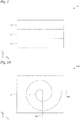
- Figure 1 is a schematic sectional view of a heating device 10 according to an embodiment of the present invention.
- the heating device 10 can be of the induction type and comprises an induction element 11, an induced element 13, and a first dielectric element 12 placed between the induction element 11 and the induced element 13.
- the induction element 11 can be any element able to generate a variable magnetic field, for example a coil, a spiral, or more generally a conductive element or any device configured to be able to generate a variable magnetic field.
- the first dielectric element 12 is any element able to electrically insulate the induction element 11 from the induced element 13, for example also vacuum space or else an air layer.
- the induced element is any one of the previously described films. More in general, the induced element can be any material by which it is possible to generate heat by means of electromagnetic field induction, for example ferromagnetic metals.
- the induced element 13 comprises a metal alloy containing a first metal or a first mixture of metals in a percentage between 90% and 99.99% by weight to the total weight and containing a second metal or a second mixture of metals in a percentage between 0.01% and 10% by weight to the total weight.
- the first metal is an amagnetic metal, for example diamagnetic or paramagnetic or antiferromagnetic metal, or the first mixture of metals is amagnetic (on the whole) or exclusively comprises non-magnetic metals.
- the second metal is a ferromagnetic or ferrimagnetic metal, or the second mixture of metals is magnetic on the whole or exclusively comprises ferromagnetic or ferrimagnetic metals.
- This embodiment allows making an induction heating device having an advantageously compact shape and excellent operation characteristics.
- the induced element 13 has thickness lower or equal to 10 cm, as previously described. Alternatively, in other preferred embodiments, the induced element 13 has thickness between 5 ⁇ m and 700 ⁇ m, and more preferably between 5 ⁇ m and 200 ⁇ m. Thanks to these embodiments, it is possible to make a particularly compact induction heating device 10. As it will be described herein below, this allows in case to make a flexible induction heating device 10 that can be applied to curved surfaces, even flexible or with varying curvature. In other embodiments, as it will be described herein below, such a thickness of the induced element 13 allows an easy integration with different building or food or furniture materials or materials for the person, without having negative impact on their thickness.
- Figure 2A schematically depicts a top view of an induction heating device 10A.
- the induction element 11 comprises a first conductive element 14 of which at least part has spiral or equivalent shape.
- the conductive element 14 can be any element able to conduct electricity, for example an electrical wire, having solid cross-section or hollow cross-section, an electric deposited track of a PCB, metallic lines deposited and/or printed on the dielectric element 12, in case multi-wire, etc.
- the conductive element 14 can be covered with resin, plastics, or any type of dielectric sheath in addition to, or replacing, the dielectric element 12.
- the conductive element 14 could comprise a plurality of conductive elements similar or different to/from one another.
- the conductive element 14 is wound with spiral shape having two ends 14A and 14B.
- the spiral has no specific geometrical configuration. Different types of spirals could be implemented and generally the term spiral has to be understood as a shape wound round a central determined point, progressively approaching or moving away, depending on how the curve is run. In particular, as it will be depicted herein below, also spirals having triangular, square development, or more generally a development at least partially rectilinear and not completely curvilinear, can be implemented.
- the diameter of the spiral or equivalent diameter of the plate measures from 1 mm to 1 m, more preferably from 3 cm to 30 cm.
- the conductive element 14 comprises one or more conductive materials selected, for example, in the group comprising copper, tungsten, brass, aluminium, iron, and the alloys comprising the same.
- the two ends 14A and 14B of the spiral terminate on two different sides of the induction heating element 10A.
- the present invention is not limited to this case and the two ends 14A and 14B can terminate on any side of the induction heating element independently from one another.
- the two ends 14A and 14B can terminate on the same side of the induction heating element 10B, so that to advantageously allow a simple electrical connection of the two ends to a generator or more generally a source of electrical power.
- the spiral shape of the conductive element 14 is made by a single winding of the conductive element 14.
- the present invention is not limited to this specific embodiment and, as for example depicted in Figure 2C , also a double winding of the conductive element 14 is possible.
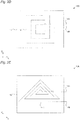
- FIGs 2D and 2E schematically depict two embodiments in which the spiral of the conductive element 14 has polygonal development, respectively square in Figure 2D and triangular in Figure 2E .
- first conductive element 14 comprises the ends 14A, 14B
- second conductive element 15 comprises the ends 15A, 15B.
- the position of the ends can be freely configured.
- the ends 14A, 4B and the ends 15A, 5B can be connected on the same device side, which advantageously simplifies the connection to a generator.
- the conductive elements 14, 15 in the two spirals of Figure 2F are depicted as wound in opposite directions, particularly counter-clockwise for the conductive element 14 and clockwise for the conductive element 15, the present invention is not limited to this configuration and the conductive elements 14, 15 could have in case the same winding direction in other embodiments.
- an induction heating device 10G comprises six conductive elements 14-19.
- the present invention is not limited to this embodiment and different types of spirals, in case also having different size, could be implemented in the same induction heating device.
- the dielectric element 12 has thickness from 1 ⁇ m to 10 cm.
- the dielectric element 12 has very thin thickness, it is possible to obtain an induction heating device having restrained thickness allowing to have a flexible induction heating device and thus applicable to curved surfaces, also in case of variable curvature.
- one or more materials can be used as dielectric element for example plastic, resin, glass, ceramic, wood, conglomerate of powdered oxides, stone.
- the device can be easily integrated in objects, tools and devices, household and personal grooming items, structures, etc.
- the first dielectric element 12 is wound round the induction element 11. This can be the case, for example, of an insulating sheath wound round a conductive wire.
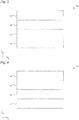
- Figure 3 schematically depicts a sectional view of an induction heating device 30 according to an embodiment of the present invention.
- the device 30 differs from the device 10 because of the presence of a second, flexible or rigid, dielectric element 31 placed on the induction element 11 at the side opposite to the first dielectric element 12.
- Figure 4 schematically depicts a sectional view of an induction heating device 40 according to an embodiment of the present invention.
- the device 40 differs from the device 10 because of the presence of a third, flexible or rigid, dielectric element 41 placed on the induced element 13 at the side opposite to the first dielectric element 12.
- the considerations previously set forth for the dielectric element 12 can also be applied to one or more of the flexible or rigid dielectric elements 31 and 41.
- the embodiments of Figure 3 and Figure 4 can be combined one another, to obtain an induction heating device comprising both the dielectric element 31 and the dielectric element 41.
- An induction heating element with three layers comprising an induction element 11 having thickness from 3 ⁇ m to 2 cm, a dielectric layer having thickness from 1 ⁇ m to 10 cm, and an induced element 13 having thickness equal or lower than 10 cm, more preferably between 10 and 700 ⁇ m.
- An induction heating element with five layers comprising a dielectric element 31 having thickness from 5 ⁇ m to 20 cm, preferably from 5 ⁇ m to 1 cm, an induction element 11 having thickness from 3 ⁇ m to 2 cm, a dielectric layer 12 having thickness from 1 ⁇ m to 10 cm, an induced element 13 having thickness equal or lower than 10 cm, more preferably between 10 and 700 ⁇ m, and a dielectric element 41 having thickness from 1 ⁇ m to 20 cm.
- An induction heating element comprising:
- the total thickness of the heating element is about 25 mm.
- the thermography detected fields heated up to 126° on the outermost surface, in about 25 minutes, with a conversion efficiency of the electric energy to thermal energy higher than 92%.
- An induction heating element comprising:
- the total thickness of the heating element is about 6 mm.
- the thermography detects fields heated up to 250°C on the outermost surface.
- Rectangular plate having dimensions 195 mm by 105 mm, composed of the following planes: - insulating element having non-inductive magnetic shield with thickness of 0.2 mm; - induction element composed of a flat coil composed of 12 windings starting from the external perimeter by using an enameled monofilament conductive element made of copper having conductive section of 1 mm; - dielectric insulating element made of Vetronite having thickness of 4 mm; - amagnetic inductive foil composed of two foils of about 6 ⁇ made of a so-composed alloy: Diamagnetic metals Aluminium 98% Ferromagnetic Metal Iron 1.2% Other amagnetic metals in traces 0.8%
- the foils are spaced by a carbon layer of 0.5 mm. With a power of 1000 watt, they have reached the temperature of 150°C in less than 12 seconds.
- the device With a power of 65 watt, the device reached the temperature of about 102 °C in about 65 seconds.
- Sample 107 200 ⁇ m Fe 0.1% Cu 99.8% rem.
- Sample 108 1.3 mm Fe 0.1% Cu 99.8% rem.
- Sanple 109 5 mm Fe 2% Cu 97.9% rem.
- Sample 110 2.1 mm Fe 2% Cu 97.9% rem.
- SAMPLES SP MF MA AA Sample 111 1 mm Fe 2% Cu 97.9% rem.
- Sample 112 500 ⁇ m Fe 2% Cu 97.9%. rem.
- Sample 113 200 ⁇ m Fe 2% Cu 97.9% rem.
- Sample 114 100 ⁇ m Fe 2% Cu 97.9% rem.
- Sample 123 100 ⁇ m Fe 0.45% 4 5% Al 99.07% rem.
- Sample 125 500 ⁇ m Fe 0.1% 8% Ag 99.8% rem.
- Sample 126 250 ⁇ m Fe 0.1% Ag 99.8% rem.
- Sample 127 100 ⁇ m Fe 0.1% Ag 99.8% rem.
- Sample 129 55 ⁇ m Fe 2% Ag 97.9% rem.
- Sample 132 10 10 ⁇ m Fe 2.68% Al 95% rem.
- Sample 142 200 ⁇ m Fe 0.1% Cu 70% Zn 29.80% rem. Sample 143 1.5 mm Fe 2.72% Al 93.08% Si 4.06% rem. SAMPLES SP MF MA AA Sample 144 840 ⁇ m Fe 0.617% Cu 90.54% Al 2.22% Si 5.54% rem. Sample 145 13.6 mm Fe 1.2% Ni 1.41% Al 92.22% Cu 3.08 rem. Sample 146 280 ⁇ m Fe 2% Al 85.75% Cu 0.314% Mn 2.17% Si 7.41% rem. Sample 147 300 ⁇ m Fe 0.02% Cu 62.80% Zn 37.16% rem. Sample 148 2 mm Fe 1.52% Ni 8.28% Cu 89.2% rem. sample 149 0.8 mm Fe 0.02% Ti 99.97% rem.
- Each sample has square shape with side dimensions of 5 cm (surface of 25 cm 2 ) .
- Each sample has been subjected to the action of an electromagnetic field generated by a flat circular spiral having an external diameter of 73 mm and an internal diameter of 6 mm, by using multi-conductive copper wire of 1.5 mm without external sheath.
- Each sample has been placed in parallel to the plane where the induction spiral lies by aligning the respective centers, separating the spiral and the sample with a fiberglass plate having dimensions 100x100x2.5 mm.
- the electromagnetic field is obtained by powering the spiral with a sinusoid generated by a ZVS oscillator of Royer type, having power modulated at PWM at 24V and 20% duty cycle.
- Duration of the test 30 seconds per each sample.
- a second dielectric element 12 will be placed between the induction element 11 and the second induced element 13.
- a layer of adhesive material can have thickness from 3 to 100 ⁇ m.
- Figures 5A-5G schematically depicts different embodiments of the induced element 13-13G.
- the induced element 13 has the shape of a flat film or foil, as previously described.
- the induced element 13B shows an embossing 53B increasing the exchange surface with the magnetic field generated by the induction element 11.
- the induced elements 13C-13E can be constituted by flanked or overlapped or crossed stripes 53C-53E of induced element, which have the same or different dimension, the same or different relative spacing, in a single layer or multilayer, and orientation respectively vertical, horizontal, and oblique.
- Each of the foils 53C-53E can be made as previously described for the single foil, or film, and subsequently joined to the others. In some specific embodiments, each of the foils can have the smallest dimension typically between 4 ⁇ and 3 cm.
- the induced element 13F is made by crossing and overlapping the horizontal foils 53D and the vertical foils 53C.
- the induced element 13G is made by compacting the concertina fold foils.
- the induction heating device can show convex shape.
- at least the induced element can show convex surface, preferably substantially closed on itself, or anyway having an angle of at least 180°.
- the induction heating device is not flat but shows a shape at least partially closed on itself.
- the induction element 11, or the surface defined by the induction element 11, can have convex surface, with considerations similar to those made for the induced element. The same is true for any one of the dielectric elements 12, 31 and 41.
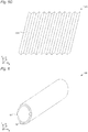
- an induction heating device 60 can have a substantially tubular shape obtained by winding any one of the heating devices previously described, in case above a supporting tube 61.
- the dimensions of the radius can typically be from 5 mm to 1 m.
- the section of the supporting tube 61 can be circular, oval, or polygonal, or more in general any section showing at least one convex surface.
- the supporting tube 61 can be completely closed on 360 degrees in the XY plane, whereas the induction heating device 10 placed on the supporting tube 61 can only be closed partially on itself in the XY plane, i.e. can show a convex surface defining an angle lower than 360 degrees, but preferably higher than 180 degrees.
- the supporting tube can be absent and the induction heating device 60 can be obtained by closing the induction heating device 10 on itself, or any one of the induction heating devices described, so that to form a tube.
- the induction heating device 60 it is possible, for example, for fluid to flow, such as air, more generally gas, water or oil, or else solids such as grains or powders inside the device 60, by heating them.
- the fluids or solids flow directly in contact with the innermost layer of the device, for example the induced element 13 or the dielectric element 41.
- the fluids or solids could be uniquely in contact with the supporting tube 61, in case wherein the heating device 10 is placed outside to the supporting tube 61 to integrally or partially cover the supporting tube 61 as depicted in Figure 6 , or they will be, integrally or partially, in contact with the heating device 10 in case wherein the heating device 10 is placed inside the supporting tube 61, thus integrally or partially covering it.
- the heating device 10 is placed outside the supporting tube 61, it is advantageously possible to circulate fluids or solids, inside the supporting tube 61, that could corrode or compromise the operation of the device 60.
- the supporting tube 61 can be, for example, a plastic tube, a tube for piping made of PVC, a tube of drinking water or a glass tube, for example for applications in the laboratory glassware.
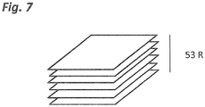
- Figure 7 the induced element composed of overlapped foils 53R is depicted in a tridimensional form. Between one foil and the other one it is possible to provide the presence of a dielectric element, preferably air.
- the induced element 13 is any one of the induced elements previously described.
- the induced element 13 shows a circular section having diameter of 80 mm and length of 60 cm.
- the foil constituting the tube is concertina fold to ease the induction element 11 constituted by enameled copper wire having diameter of 1.2 mm, to be housed.
- thermography detected a temperature of 50°C inside the tube, reached in less than 10 minutes.
- An embodiment of the present invention is further referring to a kit for making a device according to any one of the previous embodiments and comprises an induction element 11, and/or an induced element 13, and/or a first dielectric element 12 to be placed between the induction element 11 and the induced element 13.
- a kit for making a device according to any one of the previous embodiments and comprises an induction element 11, and/or an induced element 13, and/or a first dielectric element 12 to be placed between the induction element 11 and the induced element 13.
- one or more of these three elements can be provided separately and assembled only during installation and/or use of the device.
- the induction heating device comprises at least one induction element 11 and one induced element 13.
- induction heating devices in which there are more layers of induction elements 11 and/or induced elements 13.
- a single induced element 13 could be combined with two induction elements 11, one per side of the induced element 13, to double the available power.
- a single induction element 11 could be combined with two induced elements 13, on the same side or else one per side of the induction element 11, to heat both sides of the device.
Landscapes
- Physics & Mathematics (AREA)
- Electromagnetism (AREA)
- General Induction Heating (AREA)
- Discharge Heating (AREA)
- Thermotherapy And Cooling Therapy Devices (AREA)
- Control And Other Processes For Unpacking Of Materials (AREA)
- Soft Magnetic Materials (AREA)
- Hard Magnetic Materials (AREA)
- Magnetic Ceramics (AREA)
- Cookers (AREA)
Priority Applications (1)
| Application Number | Priority Date | Filing Date | Title |
|---|---|---|---|
| PL17751477T PL3485702T3 (pl) | 2016-07-18 | 2017-07-14 | Element grzejny, jego wykorzystanie i zestaw |
Applications Claiming Priority (2)
| Application Number | Priority Date | Filing Date | Title |
|---|---|---|---|
| IT102016000074867A IT201600074867A1 (it) | 2016-07-18 | 2016-07-18 | Dispositivo di riscaldamento, uso e kit |
| PCT/IB2017/054272 WO2018015856A2 (en) | 2016-07-18 | 2017-07-14 | Heating device, its use and kit |
Publications (2)
| Publication Number | Publication Date |
|---|---|
| EP3485702A2 EP3485702A2 (en) | 2019-05-22 |
| EP3485702B1 true EP3485702B1 (en) | 2020-04-15 |
Family
ID=57708666
Family Applications (1)
| Application Number | Title | Priority Date | Filing Date |
|---|---|---|---|
| EP17751477.5A Active EP3485702B1 (en) | 2016-07-18 | 2017-07-14 | Heating device, its use and kit |
Country Status (8)
| Country | Link |
|---|---|
| US (1) | US11116048B2 (it) |
| EP (1) | EP3485702B1 (it) |
| JP (1) | JP2019521492A (it) |
| CN (1) | CN109479348B (it) |
| ES (1) | ES2832891T3 (it) |
| IT (1) | IT201600074867A1 (it) |
| PL (1) | PL3485702T3 (it) |
| WO (1) | WO2018015856A2 (it) |
Families Citing this family (3)
| Publication number | Priority date | Publication date | Assignee | Title |
|---|---|---|---|---|
| EP3672361B1 (en) * | 2018-12-18 | 2021-07-07 | Aptiv Technologies Limited | Heating device |
| EP3672362B2 (en) * | 2018-12-18 | 2024-01-17 | Aptiv Technologies Limited | Heating device |
| IT201900023856A1 (it) | 2019-12-12 | 2021-06-12 | A Celli Paper Spa | Macchina e metodo per la produzione di carta a umido |
Family Cites Families (36)
| Publication number | Priority date | Publication date | Assignee | Title |
|---|---|---|---|---|
| US3684853A (en) * | 1971-10-18 | 1972-08-15 | Gen Electric | Induction surface heating unit system |
| US3814888A (en) * | 1971-11-19 | 1974-06-04 | Gen Electric | Solid state induction cooking appliance |
| US3781503A (en) * | 1971-11-19 | 1973-12-25 | Gen Electric | Solid state induction cooking appliances and circuits |
| US3786219A (en) * | 1971-12-27 | 1974-01-15 | Gen Electric | Solid state induction cooking systems for ranges and surface cooking units |
| US3742174A (en) * | 1971-12-29 | 1973-06-26 | Gen Electric | Induction cooking appliance including cooking vessel having means for transmission of temperature data by light pulses |
| JPS58188415A (ja) * | 1982-04-27 | 1983-11-02 | 有限会社南田総業 | 調理容器 |
| US4544818A (en) * | 1982-07-29 | 1985-10-01 | Asahi Giken Kogyo Kabushiki Kaisha | Cooking utensil for induction cooking apparatus |
| JPH02504591A (ja) * | 1987-08-24 | 1990-12-27 | フィスラー ゲーエムベーハー | 調理用具 |
| US5073689A (en) * | 1988-02-06 | 1991-12-17 | Shinagawa Shirorenga Kabushiki Kaisha | Zirconia refractory heating element |
| US5378879A (en) * | 1993-04-20 | 1995-01-03 | Raychem Corporation | Induction heating of loaded materials |
| JPH0942696A (ja) * | 1995-08-03 | 1997-02-14 | Matsushita Electric Ind Co Ltd | 浴室用暖房装置 |
| JPH09140564A (ja) * | 1995-11-29 | 1997-06-03 | Toshiba Home Technol Corp | 炊飯器 |
| JP3225240B2 (ja) * | 2000-01-18 | 2001-11-05 | 広島アルミニウム工業株式会社 | 電磁誘導加熱を利用した加熱保温プレート及び電磁誘導加熱調理用容器 |
| JP4647176B2 (ja) * | 2001-09-21 | 2011-03-09 | 三井ホーム株式会社 | シート材張着構造及びシート材張着方法 |
| KR100427602B1 (ko) * | 2002-02-26 | 2004-04-28 | 김명석 | 다중바닥을 구비한 주방용기와 그 제조방법 |
| JP2004000379A (ja) * | 2002-04-16 | 2004-01-08 | Mitsubishi Alum Co Ltd | 加熱用アルミニウム容器 |
| US20040229079A1 (en) * | 2002-06-28 | 2004-11-18 | Groll William A. | Composite cookware having decorative outer surface and improved induction heating characteristics |
| US7034263B2 (en) * | 2003-07-02 | 2006-04-25 | Itherm Technologies, Lp | Apparatus and method for inductive heating |
| WO2006050490A2 (en) * | 2004-11-03 | 2006-05-11 | Imura International U.S.A. | Induction cookware with ferromagnetic coating and coating method |
| JP2007075507A (ja) * | 2005-09-16 | 2007-03-29 | Miyao Company Ltd | 電磁誘導加熱調理器用容器の製造方法 |
| JP5090758B2 (ja) * | 2006-03-08 | 2012-12-05 | 東洋アルミニウム株式会社 | アルミニウム箔 |
| US8796598B2 (en) * | 2007-09-07 | 2014-08-05 | Bose Corporation | Induction cookware |
| US8796600B2 (en) * | 2007-11-30 | 2014-08-05 | Honda Motor Co., Ltd. | Induction warming system for fiber composite gas storage cylinders |
| US8803046B2 (en) * | 2009-08-11 | 2014-08-12 | Radyne Corporation | Inductor assembly for transverse flux electric induction heat treatment of electrically conductive thin strip material with low electrical resistivity |
| ES2653668T3 (es) * | 2009-09-04 | 2018-02-08 | Meyer Intellectual Properties Limited | Batería de cocina de cobre con revestimiento anodizado |
| JP5554049B2 (ja) * | 2009-11-18 | 2014-07-23 | 株式会社エムエーパッケージング | 電磁調理器用アルミニウム箔容器 |
| US8448379B2 (en) * | 2010-12-09 | 2013-05-28 | Larry Y Igarashi | Pure-grown totally concealed clean room vegetable factory |
| JP5637452B2 (ja) * | 2011-03-17 | 2014-12-10 | 住友電気工業株式会社 | 誘導加熱装置、及びそれを備える発電システム |
| KR20120119072A (ko) * | 2011-04-20 | 2012-10-30 | (주)피엔유에코에너지 | 온도 자가조절형 면상발열체를 적용한 전기레인지 및 그 제조방법 |
| JP5741468B2 (ja) * | 2012-02-10 | 2015-07-01 | 三菱電機株式会社 | 誘導加熱調理器 |
| PL2820917T3 (pl) * | 2012-03-01 | 2016-12-30 | Urządzenie do indukcyjnego nagrzewania kęsa | |
| JP6157471B2 (ja) * | 2012-08-08 | 2017-07-05 | 株式会社ブリヂストン | 金型誘導加熱装置 |
| WO2014035480A1 (en) * | 2012-08-30 | 2014-03-06 | General Electric Company | Induction furnace with uniform cooling capability |
| FR3015470B1 (fr) * | 2013-12-20 | 2018-03-16 | Eurokera S.N.C. | Plaque de cuisson par induction et procede d'obtention |
| RU2686564C2 (ru) * | 2014-04-04 | 2019-04-29 | Шелл Интернэшнл Рисерч Маатсхаппий Б.В. | Изолированные проводники, сформированные с использованием стадии окончательного уменьшения размера после термической обработки |
| ITUB20155076A1 (it) * | 2015-10-27 | 2017-04-27 | E Wenco S R L | Pellicola metallica e metodo per riscaldarla |
-
2016
- 2016-07-18 IT IT102016000074867A patent/IT201600074867A1/it unknown
-
2017
- 2017-07-14 ES ES17751477T patent/ES2832891T3/es active Active
- 2017-07-14 US US16/319,321 patent/US11116048B2/en active Active
- 2017-07-14 CN CN201780044551.XA patent/CN109479348B/zh active Active
- 2017-07-14 WO PCT/IB2017/054272 patent/WO2018015856A2/en unknown
- 2017-07-14 EP EP17751477.5A patent/EP3485702B1/en active Active
- 2017-07-14 PL PL17751477T patent/PL3485702T3/pl unknown
- 2017-07-14 JP JP2019500632A patent/JP2019521492A/ja active Pending
Non-Patent Citations (1)
| Title |
|---|
| None * |
Also Published As
| Publication number | Publication date |
|---|---|
| EP3485702A2 (en) | 2019-05-22 |
| JP2019521492A (ja) | 2019-07-25 |
| CN109479348A (zh) | 2019-03-15 |
| PL3485702T3 (pl) | 2020-09-21 |
| CN109479348B (zh) | 2021-10-19 |
| US11116048B2 (en) | 2021-09-07 |
| WO2018015856A2 (en) | 2018-01-25 |
| WO2018015856A3 (en) | 2018-03-01 |
| US20190159299A1 (en) | 2019-05-23 |
| ES2832891T3 (es) | 2021-06-11 |
| IT201600074867A1 (it) | 2018-01-18 |
Similar Documents
| Publication | Publication Date | Title |
|---|---|---|
| EP3485702B1 (en) | Heating device, its use and kit | |
| US20210076461A1 (en) | Electromagnetic wave reducing heater | |
| JP6601955B2 (ja) | 電子部品の製造方法 | |
| IL269650B1 (en) | A heating element assembly for inductively heating a substrate to create a spray | |
| JP3969456B2 (ja) | 電磁誘導加熱用複合材及び電磁誘導加熱用調理器具 | |
| KR20180066870A (ko) | 인덕션렌지용 발열모듈 및 이를 포함하는 인덕션렌지 | |
| CN111033648B (zh) | 磁膜 | |
| WO2017072656A1 (en) | Metal film and method for heating the same | |
| CN110114846A (zh) | 磁芯、线圈组件以及包括线圈组件的电子组件 | |
| CN111742379B (zh) | 用于电机的多构件磁体组件 | |
| CN106685097A (zh) | 磁性片和无线充电装置 | |
| Kennedy et al. | Analytical and FEM modeling of aluminum billet induction heating with experimental verification | |
| JPH11510997A (ja) | 誘導モータ用導電体/バックアイアン複合化セコンダリ | |
| CN101060260A (zh) | 用于发电机、电动机和变压器的铁芯绕组 | |
| CN202310439U (zh) | 中频电炉磁轭 | |
| WO2023066877A1 (en) | Induction heating device for stationary or moving material | |
| Rudnev | Systematic analysis of induction coil failures | |
| US8845957B2 (en) | Method for producing a magnetizable metal shaped body | |
| ITUB20154830A1 (it) | Inserto in lega di un materiale amagnetico e un materiale ferromagnetico, utensile per cottura ad induzione comprendente tale inserto e metodo per la realizzazione di tale utensile | |
| US9948150B2 (en) | Systems and methods for constructing laminations for electric motors | |
| WO2017009809A1 (en) | Induction heating element | |
| JP3969294B2 (ja) | 電磁誘導加熱用複合材 | |
| JP3480339B2 (ja) | 電磁誘導加熱用複合材及びその製造方法 | |
| Ruffini et al. | New magnetodielectric materials for magnetic flux control | |
| Ding et al. | Research on Polymer-Bonded Magnetic Materials for a buck converter |
Legal Events
| Date | Code | Title | Description |
|---|---|---|---|
| STAA | Information on the status of an ep patent application or granted ep patent |
Free format text: STATUS: UNKNOWN |
|
| STAA | Information on the status of an ep patent application or granted ep patent |
Free format text: STATUS: THE INTERNATIONAL PUBLICATION HAS BEEN MADE |
|
| PUAI | Public reference made under article 153(3) epc to a published international application that has entered the european phase |
Free format text: ORIGINAL CODE: 0009012 |
|
| STAA | Information on the status of an ep patent application or granted ep patent |
Free format text: STATUS: REQUEST FOR EXAMINATION WAS MADE |
|
| 17P | Request for examination filed |
Effective date: 20190214 |
|
| AK | Designated contracting states |
Kind code of ref document: A2 Designated state(s): AL AT BE BG CH CY CZ DE DK EE ES FI FR GB GR HR HU IE IS IT LI LT LU LV MC MK MT NL NO PL PT RO RS SE SI SK SM TR |
|
| AX | Request for extension of the european patent |
Extension state: BA ME |
|
| DAV | Request for validation of the european patent (deleted) | ||
| DAX | Request for extension of the european patent (deleted) | ||
| GRAP | Despatch of communication of intention to grant a patent |
Free format text: ORIGINAL CODE: EPIDOSNIGR1 |
|
| STAA | Information on the status of an ep patent application or granted ep patent |
Free format text: STATUS: GRANT OF PATENT IS INTENDED |
|
| INTG | Intention to grant announced |
Effective date: 20191120 |
|
| GRAS | Grant fee paid |
Free format text: ORIGINAL CODE: EPIDOSNIGR3 |
|
| GRAA | (expected) grant |
Free format text: ORIGINAL CODE: 0009210 |
|
| STAA | Information on the status of an ep patent application or granted ep patent |
Free format text: STATUS: THE PATENT HAS BEEN GRANTED |
|
| AK | Designated contracting states |
Kind code of ref document: B1 Designated state(s): AL AT BE BG CH CY CZ DE DK EE ES FI FR GB GR HR HU IE IS IT LI LT LU LV MC MK MT NL NO PL PT RO RS SE SI SK SM TR |
|
| REG | Reference to a national code |
Ref country code: CH Ref legal event code: EP |
|
| REG | Reference to a national code |
Ref country code: DE Ref legal event code: R096 Ref document number: 602017014910 Country of ref document: DE |
|
| REG | Reference to a national code |
Ref country code: IE Ref legal event code: FG4D |
|
| REG | Reference to a national code |
Ref country code: AT Ref legal event code: REF Ref document number: 1258800 Country of ref document: AT Kind code of ref document: T Effective date: 20200515 |
|
| REG | Reference to a national code |
Ref country code: NL Ref legal event code: FP |
|
| REG | Reference to a national code |
Ref country code: LT Ref legal event code: MG4D |
|
| PG25 | Lapsed in a contracting state [announced via postgrant information from national office to epo] |
Ref country code: NO Free format text: LAPSE BECAUSE OF FAILURE TO SUBMIT A TRANSLATION OF THE DESCRIPTION OR TO PAY THE FEE WITHIN THE PRESCRIBED TIME-LIMIT Effective date: 20200715 Ref country code: IS Free format text: LAPSE BECAUSE OF FAILURE TO SUBMIT A TRANSLATION OF THE DESCRIPTION OR TO PAY THE FEE WITHIN THE PRESCRIBED TIME-LIMIT Effective date: 20200815 Ref country code: GR Free format text: LAPSE BECAUSE OF FAILURE TO SUBMIT A TRANSLATION OF THE DESCRIPTION OR TO PAY THE FEE WITHIN THE PRESCRIBED TIME-LIMIT Effective date: 20200716 Ref country code: LT Free format text: LAPSE BECAUSE OF FAILURE TO SUBMIT A TRANSLATION OF THE DESCRIPTION OR TO PAY THE FEE WITHIN THE PRESCRIBED TIME-LIMIT Effective date: 20200415 Ref country code: PT Free format text: LAPSE BECAUSE OF FAILURE TO SUBMIT A TRANSLATION OF THE DESCRIPTION OR TO PAY THE FEE WITHIN THE PRESCRIBED TIME-LIMIT Effective date: 20200817 Ref country code: SE Free format text: LAPSE BECAUSE OF FAILURE TO SUBMIT A TRANSLATION OF THE DESCRIPTION OR TO PAY THE FEE WITHIN THE PRESCRIBED TIME-LIMIT Effective date: 20200415 Ref country code: FI Free format text: LAPSE BECAUSE OF FAILURE TO SUBMIT A TRANSLATION OF THE DESCRIPTION OR TO PAY THE FEE WITHIN THE PRESCRIBED TIME-LIMIT Effective date: 20200415 |
|
| REG | Reference to a national code |
Ref country code: AT Ref legal event code: MK05 Ref document number: 1258800 Country of ref document: AT Kind code of ref document: T Effective date: 20200415 |
|
| PG25 | Lapsed in a contracting state [announced via postgrant information from national office to epo] |
Ref country code: HR Free format text: LAPSE BECAUSE OF FAILURE TO SUBMIT A TRANSLATION OF THE DESCRIPTION OR TO PAY THE FEE WITHIN THE PRESCRIBED TIME-LIMIT Effective date: 20200415 Ref country code: LV Free format text: LAPSE BECAUSE OF FAILURE TO SUBMIT A TRANSLATION OF THE DESCRIPTION OR TO PAY THE FEE WITHIN THE PRESCRIBED TIME-LIMIT Effective date: 20200415 Ref country code: RS Free format text: LAPSE BECAUSE OF FAILURE TO SUBMIT A TRANSLATION OF THE DESCRIPTION OR TO PAY THE FEE WITHIN THE PRESCRIBED TIME-LIMIT Effective date: 20200415 Ref country code: BG Free format text: LAPSE BECAUSE OF FAILURE TO SUBMIT A TRANSLATION OF THE DESCRIPTION OR TO PAY THE FEE WITHIN THE PRESCRIBED TIME-LIMIT Effective date: 20200715 |
|
| PG25 | Lapsed in a contracting state [announced via postgrant information from national office to epo] |
Ref country code: AL Free format text: LAPSE BECAUSE OF FAILURE TO SUBMIT A TRANSLATION OF THE DESCRIPTION OR TO PAY THE FEE WITHIN THE PRESCRIBED TIME-LIMIT Effective date: 20200415 |
|
| REG | Reference to a national code |
Ref country code: DE Ref legal event code: R097 Ref document number: 602017014910 Country of ref document: DE |
|
| PG25 | Lapsed in a contracting state [announced via postgrant information from national office to epo] |
Ref country code: AT Free format text: LAPSE BECAUSE OF FAILURE TO SUBMIT A TRANSLATION OF THE DESCRIPTION OR TO PAY THE FEE WITHIN THE PRESCRIBED TIME-LIMIT Effective date: 20200415 Ref country code: CZ Free format text: LAPSE BECAUSE OF FAILURE TO SUBMIT A TRANSLATION OF THE DESCRIPTION OR TO PAY THE FEE WITHIN THE PRESCRIBED TIME-LIMIT Effective date: 20200415 Ref country code: RO Free format text: LAPSE BECAUSE OF FAILURE TO SUBMIT A TRANSLATION OF THE DESCRIPTION OR TO PAY THE FEE WITHIN THE PRESCRIBED TIME-LIMIT Effective date: 20200415 Ref country code: SM Free format text: LAPSE BECAUSE OF FAILURE TO SUBMIT A TRANSLATION OF THE DESCRIPTION OR TO PAY THE FEE WITHIN THE PRESCRIBED TIME-LIMIT Effective date: 20200415 Ref country code: EE Free format text: LAPSE BECAUSE OF FAILURE TO SUBMIT A TRANSLATION OF THE DESCRIPTION OR TO PAY THE FEE WITHIN THE PRESCRIBED TIME-LIMIT Effective date: 20200415 Ref country code: DK Free format text: LAPSE BECAUSE OF FAILURE TO SUBMIT A TRANSLATION OF THE DESCRIPTION OR TO PAY THE FEE WITHIN THE PRESCRIBED TIME-LIMIT Effective date: 20200415 |
|
| PLBE | No opposition filed within time limit |
Free format text: ORIGINAL CODE: 0009261 |
|
| STAA | Information on the status of an ep patent application or granted ep patent |
Free format text: STATUS: NO OPPOSITION FILED WITHIN TIME LIMIT |
|
| PG25 | Lapsed in a contracting state [announced via postgrant information from national office to epo] |
Ref country code: MC Free format text: LAPSE BECAUSE OF FAILURE TO SUBMIT A TRANSLATION OF THE DESCRIPTION OR TO PAY THE FEE WITHIN THE PRESCRIBED TIME-LIMIT Effective date: 20200415 Ref country code: SK Free format text: LAPSE BECAUSE OF FAILURE TO SUBMIT A TRANSLATION OF THE DESCRIPTION OR TO PAY THE FEE WITHIN THE PRESCRIBED TIME-LIMIT Effective date: 20200415 |
|
| 26N | No opposition filed |
Effective date: 20210118 |
|
| PG25 | Lapsed in a contracting state [announced via postgrant information from national office to epo] |
Ref country code: LU Free format text: LAPSE BECAUSE OF NON-PAYMENT OF DUE FEES Effective date: 20200714 |
|
| PG25 | Lapsed in a contracting state [announced via postgrant information from national office to epo] |
Ref country code: SI Free format text: LAPSE BECAUSE OF FAILURE TO SUBMIT A TRANSLATION OF THE DESCRIPTION OR TO PAY THE FEE WITHIN THE PRESCRIBED TIME-LIMIT Effective date: 20200415 |
|
| REG | Reference to a national code |
Ref country code: ES Ref legal event code: FG2A Ref document number: 2832891 Country of ref document: ES Kind code of ref document: T3 Effective date: 20210611 |
|
| PG25 | Lapsed in a contracting state [announced via postgrant information from national office to epo] |
Ref country code: MT Free format text: LAPSE BECAUSE OF FAILURE TO SUBMIT A TRANSLATION OF THE DESCRIPTION OR TO PAY THE FEE WITHIN THE PRESCRIBED TIME-LIMIT Effective date: 20200415 Ref country code: CY Free format text: LAPSE BECAUSE OF FAILURE TO SUBMIT A TRANSLATION OF THE DESCRIPTION OR TO PAY THE FEE WITHIN THE PRESCRIBED TIME-LIMIT Effective date: 20200415 |
|
| PG25 | Lapsed in a contracting state [announced via postgrant information from national office to epo] |
Ref country code: MK Free format text: LAPSE BECAUSE OF FAILURE TO SUBMIT A TRANSLATION OF THE DESCRIPTION OR TO PAY THE FEE WITHIN THE PRESCRIBED TIME-LIMIT Effective date: 20200415 |
|
| PGFP | Annual fee paid to national office [announced via postgrant information from national office to epo] |
Ref country code: NL Payment date: 20230628 Year of fee payment: 7 Ref country code: IE Payment date: 20230627 Year of fee payment: 7 Ref country code: FR Payment date: 20230627 Year of fee payment: 7 |
|
| PGFP | Annual fee paid to national office [announced via postgrant information from national office to epo] |
Ref country code: PL Payment date: 20230628 Year of fee payment: 7 |
|
| PGFP | Annual fee paid to national office [announced via postgrant information from national office to epo] |
Ref country code: BE Payment date: 20230628 Year of fee payment: 7 |
|
| PGFP | Annual fee paid to national office [announced via postgrant information from national office to epo] |
Ref country code: TR Payment date: 20230704 Year of fee payment: 7 Ref country code: IT Payment date: 20230627 Year of fee payment: 7 Ref country code: GB Payment date: 20230627 Year of fee payment: 7 Ref country code: ES Payment date: 20230815 Year of fee payment: 7 Ref country code: CH Payment date: 20230801 Year of fee payment: 7 |
|
| PGFP | Annual fee paid to national office [announced via postgrant information from national office to epo] |
Ref country code: DE Payment date: 20230628 Year of fee payment: 7 |