EP3484397B1 - Medizinisches instrument mit mehreren kabeln - Google Patents
Medizinisches instrument mit mehreren kabeln Download PDFInfo
- Publication number
- EP3484397B1 EP3484397B1 EP17828154.9A EP17828154A EP3484397B1 EP 3484397 B1 EP3484397 B1 EP 3484397B1 EP 17828154 A EP17828154 A EP 17828154A EP 3484397 B1 EP3484397 B1 EP 3484397B1
- Authority
- EP
- European Patent Office
- Prior art keywords
- cables
- pulleys
- cable
- input
- piece
- Prior art date
- Legal status (The legal status is an assumption and is not a legal conclusion. Google has not performed a legal analysis and makes no representation as to the accuracy of the status listed.)
- Active
Links
Images



Classifications
-
- A—HUMAN NECESSITIES
- A61—MEDICAL OR VETERINARY SCIENCE; HYGIENE
- A61B—DIAGNOSIS; SURGERY; IDENTIFICATION
- A61B34/00—Computer-aided surgery; Manipulators or robots specially adapted for use in surgery
-
- A—HUMAN NECESSITIES
- A61—MEDICAL OR VETERINARY SCIENCE; HYGIENE
- A61B—DIAGNOSIS; SURGERY; IDENTIFICATION
- A61B34/00—Computer-aided surgery; Manipulators or robots specially adapted for use in surgery
- A61B34/30—Surgical robots
-
- A—HUMAN NECESSITIES
- A61—MEDICAL OR VETERINARY SCIENCE; HYGIENE
- A61B—DIAGNOSIS; SURGERY; IDENTIFICATION
- A61B34/00—Computer-aided surgery; Manipulators or robots specially adapted for use in surgery
- A61B34/70—Manipulators specially adapted for use in surgery
- A61B34/71—Manipulators operated by drive cable mechanisms
-
- A—HUMAN NECESSITIES
- A61—MEDICAL OR VETERINARY SCIENCE; HYGIENE
- A61B—DIAGNOSIS; SURGERY; IDENTIFICATION
- A61B17/00—Surgical instruments, devices or methods
- A61B17/28—Surgical forceps
- A61B17/29—Forceps for use in minimally invasive surgery
-
- A—HUMAN NECESSITIES
- A61—MEDICAL OR VETERINARY SCIENCE; HYGIENE
- A61B—DIAGNOSIS; SURGERY; IDENTIFICATION
- A61B17/00—Surgical instruments, devices or methods
- A61B2017/00477—Coupling
-
- A—HUMAN NECESSITIES
- A61—MEDICAL OR VETERINARY SCIENCE; HYGIENE
- A61B—DIAGNOSIS; SURGERY; IDENTIFICATION
- A61B17/00—Surgical instruments, devices or methods
- A61B17/28—Surgical forceps
- A61B17/29—Forceps for use in minimally invasive surgery
- A61B2017/2901—Details of shaft
- A61B2017/2902—Details of shaft characterized by features of the actuating rod
- A61B2017/2903—Details of shaft characterized by features of the actuating rod transferring rotary motion
-
- A—HUMAN NECESSITIES
- A61—MEDICAL OR VETERINARY SCIENCE; HYGIENE
- A61B—DIAGNOSIS; SURGERY; IDENTIFICATION
- A61B17/00—Surgical instruments, devices or methods
- A61B17/28—Surgical forceps
- A61B17/29—Forceps for use in minimally invasive surgery
- A61B2017/2926—Details of heads or jaws
- A61B2017/2927—Details of heads or jaws the angular position of the head being adjustable with respect to the shaft
- A61B2017/2929—Details of heads or jaws the angular position of the head being adjustable with respect to the shaft with a head rotatable about the longitudinal axis of the shaft
-
- A—HUMAN NECESSITIES
- A61—MEDICAL OR VETERINARY SCIENCE; HYGIENE
- A61B—DIAGNOSIS; SURGERY; IDENTIFICATION
- A61B34/00—Computer-aided surgery; Manipulators or robots specially adapted for use in surgery
- A61B34/70—Manipulators specially adapted for use in surgery
- A61B34/71—Manipulators operated by drive cable mechanisms
- A61B2034/715—Cable tensioning mechanisms for removing slack
-
- A—HUMAN NECESSITIES
- A61—MEDICAL OR VETERINARY SCIENCE; HYGIENE
- A61B—DIAGNOSIS; SURGERY; IDENTIFICATION
- A61B90/00—Instruments, implements or accessories specially adapted for surgery or diagnosis and not covered by any of the groups A61B1/00 - A61B50/00, e.g. for luxation treatment or for protecting wound edges
- A61B90/36—Image-producing devices or illumination devices not otherwise provided for
- A61B90/37—Surgical systems with images on a monitor during operation
- A61B2090/371—Surgical systems with images on a monitor during operation with simultaneous use of two cameras
Definitions
- Robotically controlled instruments such as employed for minimally invasive medical procedures often employ a tool or end effector or other manipulation element at the distal end of an extended instrument shaft.
- the terms "robot” or “robotically” and the like include teleoperation or telerobotic aspects.
- the instrument shaft and the distal tool generally have small diameters, often less than a centimeter, to minimize the size of incisions or natural lumens needed for insertion of the instrument.
- the distal tools are often remotely operated or actuated via thin drive members (e.g., tendons or rods) that extend between the distal tool and a transmission, sometimes referred to as the backend mechanism of the instrument.
- the backend mechanism of a replaceable instrument is generally configured to removably couple to actuators (e.g., a motor pack) in a docking port of a robot.
- the robot can then control the actuators and apply force through the backend mechanism to the drive members and through the drive members to the distal tool of the instrument.
- Medical instruments that have many degrees of freedom of movement typically require many drive members, and backend mechanisms that accommodate the transition from the layout of a docking port of a robot to the layout of the drive members in the instrument shaft can be complex and difficult to assemble.
- Reference D1 discloses surgical assemblies and related methods that provide for decoupling of instrument shaft roll and end effector actuation.
- the surgical assembly includes a base, an instrument shaft rotationally mounted to the base, an end effector supported at a distal end of the instrument shaft and including an actuation mechanism driven by a rotational motion, a drive shaft rotationally coupled with the actuation mechanism and configured to provide the rotational motion to the actuation mechanism, and a differential rotationally coupled to the drive shaft and receiving a first input motion and a second input motion.
- the differential combines the first and second input motions to generate an output motion that rotates the drive shaft.
- the first input motion is rotationally coupleable to an actuation source.
- the second input motion is coupled to rotation of the instrument shaft relative to the base.
- Reference D2 ( US 2010/011900 A1 ) describes a medical instrument guiding two sets of cables respectively through a first and a second set of pulleys into an instrument shaft to deflect a wrist mechanism.
- a medical instrument may provide efficient routing of actuation cables and relatively simple assembly process for complex medical instruments.
- a medical instrument including a chassis, input spindles mounted in the chassis, upper and lower cables wound around the input spindles, and an instrument shaft extending from the chassis and including a mechanical structure providing multiple degrees of freedom of motion.
- the upper and lower cables may connect to the mechanical structure so that rotations of the input spindles actuate respective degrees of freedom.
- Lower pulleys may be mounted at a first level to receive the lower cables from the input spindles and to redirect the lower cables toward the instrument shaft.
- Upper pulleys may be mounted at a second level to receive the upper cables from the input spindles and redirect the upper cables through the first level and toward the instrument shaft.
- the method may include: mounting lower pulleys on a first piece of a chassis of the medical instrument; feeding lower cables from an instrument shaft of the medical instrument over the lower pulleys; attaching a second piece of the chassis to the first piece so that at least portions of the lower cables are between the lower pulleys and the second piece; mounting upper pulleys in positions such that the second piece is between the upper pulleys and the lower pulleys; and feeding upper cables from the instrument shaft over the upper pulleys.
- Yet another specific implementation is a medical instrument including input spindles, lower cables respectively wound around the input spindles, upper cables respectively wound around the input spindles, and an instrument shaft extending from a chassis in which the input spindles are mounted.
- a mechanical structure on the instrument shaft has multiple degrees of freedom of motion, and the upper and lower cables connect to the structure such that rotations the input spindles respectively actuate the degrees of freedom.
- the lower or upper cables may extend between the input spindles and the instrument shaft without crossing, and paths of the other upper or lower cables cross between the input spindles and the instrument shaft.
- the crossing in one set of cables may allow the upper cable and the lower cable that wrap around the same input spindle to be more efficiently directed toward locations on opposite sides of a central axis of the instrument shaft, which may improve mechanical efficiency of actuation of the mechanical structure.
- a backend mechanism of a robotically controlled medical instrument routes cables from multiple input spindles to an instrument shaft of the instrument and employs a routing that allows simple assembly using few components.
- Cables and associated pulleys in an instrument may be particularly grouped by level or height relative to the instrument shaft, and lower cables may be fit on pulleys mounted in a lower chassis piece before a next, higher chassis piece and pulleys for upper cables are attached to the lower chassis piece.
- a two-level system is particularly effective in a self-antagonistic system in which each input spindle has a pair of two associated cables that are wrapped around the input spindle in opposite directions and at different heights so that one cable pays in in one direction and the other cable pays out in an opposite direction as the spindle rotates.
- the cable routing leaves space for other components of the backend of a medical instrument, for example, to allow control or actuation of instrument shaft roll, grip drive, electrical connectors, and latching mechanisms that attach the backend mechanism to a robot.
- the cable routing can also position cables paired in opposition in the instrument shaft, so that the paired cables can efficiently actuate opposite directions of motion of a degree of freedom of the instrument.
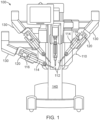
- Fig. 1 shows an example of a medical system 100 using replaceable medical instruments 110.
- System 100 which may, for example, be a da Vinci ® Surgical System commercialized by Intuitive Surgical, Inc., may particularly employ multiple surgical instruments 110, each of which is removably mounted in a docking port 120 on a manipulator arm 130 of a robot 140.
- a sterile barrier (not shown) including a drape and adaptors for instruments 110 may be between instruments 110 and robot 140, so that robot 140, including manipulator arms 130 and docking ports 120, is outside a sterile environment for a patient. Accordingly, robot 140 may not need to be sterilized between medical procedures.
- instruments 110 which may be used in the sterile environment and may contact the patient, are compact and removable so that instruments 110 may be sterilized or replaced between medical procedures performed using system 100.
- Instruments 110 may vary in structure and purpose but may still be interchangeable, so that instruments 110 mounted in docking ports 120 of robot 140 can be selected for a particular medical procedure or changed during a medical procedure to provide the clinical functions needed.
- Each instrument 110 generally includes an end effector or distal tool 112, an instrument shaft 114, and a backend mechanism 116.
- Distal tools 112 may have different designs to implement many different functions.
- distal tools 112 for different instruments 110 may have many different shapes or sizes and may include forceps, graspers, scalpels, scissors, cautery tools, or needle drivers to name a few possibilities, and instruments 110 having different distal tools 112 may be mounted on different arms 130 of robot 140 and may work cooperatively in the same work site.
- An endoscopic camera for example, a stereoscopic camera, can also be mounted on an arm to provide visual information, particularly images, of the work site in which distal tools 112 of instruments 110 may be operating.
- Docking ports 120 may include actuators, such as drive motors, that provide mechanical power for actuation of mechanical structures in instruments 110, drive couplings that connect the actuators to inputs of instruments 110, and systems for establishing and maintaining a sterile barrier between instruments 110 and the rest of medical system 100. Docking ports 120 may additionally include an electrical interface to provide power to instruments 110 or for communication with instruments 110, for example, to identify the type of instrument 110 in a docking port 120, to access parameters of instruments 110, or to receive information from sensors in instruments 110. For example, the electrical interface may convey to robot 140 measurements such as measurements of the position, orientation, or pose of distal tool 112 and instrument shaft 114 of an instrument 110.
- actuators such as drive motors, that provide mechanical power for actuation of mechanical structures in instruments 110, drive couplings that connect the actuators to inputs of instruments 110, and systems for establishing and maintaining a sterile barrier between instruments 110 and the rest of medical system 100. Docking ports 120 may additionally include an electrical interface to provide power to instruments 110 or for communication with instruments 110
- a computer system which may be connected to or part of robot 140 and connected to a user interface device (not shown), may receive the measurements from instrument 110 and receive user commands from a surgeon or other medical personnel and may execute software that controls arms 130 and drive motors in docking ports 120 as needed to operate instruments 110 according to the user commands.
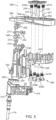
- Figs. 2A and 2B illustrate an example implementation of a medical instrument 110.
- Fig. 2A particularly shows a perspective view of an implementation having a tool 112 at the distal end of instrument shaft 114 and shows instrument shaft 114 extending from backend mechanism 116.
- distal tool 112 and instrument shaft 114 have six degrees of freedom of movement relative to backend mechanism 116.
- the six degrees of freedom correspond to: pitch and yaw rotations of a distal portion of tool 112 about two respective perpendicular axes 201 and 202 associated with a first joint mechanism 211 (also called “first joint 211”); pitch and yaw rotations or movement of jaws 213 relative to two respective perpendicular axes 203 and 204 associated with a second joint mechanism 212 (also called “second joint 212"; the joints 211,212 are sometimes referred to as “wrists”); opening or closing movement 205 of jaws 213 for "grip” actuation; and "roll” rotations of instrument shaft 114 about its central length axis 206.
- Other instruments may have more, fewer, or different degrees of freedom of movement.
- Backend mechanism 116 as shown in Fig. 2B has six input spindles 221 to 226 with engagement features that are shaped and positioned to engage actuators, e.g., drive motors, in a docking port of a robot.
- actuators e.g., drive motors
- each input spindle 221 to 226 may be coupled for actuation of a different degree of freedom of movement of the instrument, so that the robot can identify and use the correct actuator or actuators to rotate the spindle or spindles that exercise desired degrees of freedom of motion.
- the assignment input spindles 221 to 226 to corresponding degrees of freedom must be known to the robot but can be otherwise defined by an arbitrary standard or convention.
- input spindle 226 may couple to a roll mechanism that connects to a proximal end of instrument shaft 114 for rotation of instrument shaft 114 about its length axis 206 when input spindle 226 rotates.
- Input spindles 221 to 225 may couple to drive members (not shown) such as cables or rods extending though instrument shaft 114 to distal tool 112, so that the actuators in the robot can rotate input spindles 221 to 225 to control a distal mechanism including joints 211 and 212 and jaws 213. More specifically, in an exemplary implementation, rotation of input spindle 221 may control rotation or actuation of a distal portion of tool 112 about an axis 201.
- Rotation of input spindle 222 may control rotation about an axis 202.
- Rotation of input spindle 223 may control rotation about an axis 203 for yaw actuation of jaws 213, and rotation of input spindle 224 may control rotation about an axis 204 for pitch actuation of jaws 213.
- rotations of input spindles 221 to 226 may correspond to motion that is different from or more complex than simple rotations of structures about axes.
- input spindle 225 may be coupled to jaws 213 through a push-pull rod for actuation of gripping with jaws 213.
- the mechanism in tool 112 may couple a proximal portion of joint 212 to a distal portion of joint 211 for parallelogram motion, while the distal portion of joint 212 may move independently.
- Fig. 3 shows selected elements within an implementation of the backend mechanism 116 of Figs. 2A and 2B and particularly illustrates a routing in backend mechanism 116 of cables that run through instrument shaft 114 and connect to joints 211 and 212.
- the term "cable" is used herein in a broad sense to include any tendon-like structure.
- a length of cable in a medical instrument may include sections of different materials or different characteristics.
- a cable may include, for example, a stranded section where flexibility in the cable is desired (e.g., where the cable winds around a spindle, capstan, or pulley) and may include a more rigid section (e.g., a tube or rod) to limit stretching where less bending of the cable is needed.
- Fig. 3 shows selected elements within an implementation of the backend mechanism 116 of Figs. 2A and 2B and particularly illustrates a routing in backend mechanism 116 of cables that run through instrument shaft 114 and connect to joints 211 and 212.
- Input spindles 221, 222, 223, and 224 are for actuation of degrees of freedom associated with respective axes 201, 202, 203, and 204, and each input spindles 221, 222, 223, and 224 includes a pair of capstans around which a pair of actuation cables are wrapped.
- an upper capstan 231A and a lower capstan 231B may be fixed on an axle of input spindle 221 so that both capstans 231A and 231B rotate with rotation of input spindle 221.
- the terms upper and lower are used here to distinguish levels and may only apply literally when instrument shaft 114 points in a generally downward direction, as illustrated in Fig.
- a cable 241A wraps in one direction (e.g., clockwise or counterclockwise) around capstan 231A, and a cable 241B wraps in the opposite direction (e.g., counterclockwise or clockwise) around capstan 231B.
- Cable 241A extends from upper capstan 231A to an upper pulley 251 that directs cable 241A toward instrument shaft 114.
- cable 241B extends from lower capstan 231B to a lower pulley 261 that directs cable 241B toward instrument shaft 114.
- Cables 241A and 241B extend from respective pulleys 251 and 261 through a guide 280, into instrument shaft 114, and through instrument shaft 114 to connect to actuated joint mechanism 211, so that pulling cable 241A or 242B rotates a distal portion of mechanism 211 (and distal portions of tool 112) about axis 201.
- the positions of pulleys 251 and 261 and the shape of guide 280 may position cables 241A and 241B on opposite sides of the center or length axis 206 of instrument shaft 114, which may allow cable 241A to efficiently drive motion of mechanism 211 in one direction or sense about axis 201 and also allow cable 241B to efficiently drive motion of mechanism 211 in an opposite direction or sense about axis 201.
- Each input spindle 222, 223, or 224 similarly includes an axle through a pair of capstans 232A and 232B, 233A and 233B, or 234A and 234B around which a pair of cables 242A and 242B, 243A and 243B, or 244A and 244B wrap in opposite directions, and cables 242A, 242B, 243A, 243B, 244A, and 244B pass over respective pulleys 252, 262, 253, 263, 254, and 264 and run through guide 280 and instrument shaft 114.
- cables 242A and 242B connect to joint mechanism 211
- cables 243A, 243B, 244A, and 244B connect to joint mechanism 212.
- Each pair of cables 242A and 242B, 243A and 243B, and 244A and 244B as described above includes one cable wound in one direction (e.g., clockwise) about an input spindle 221, 222, 223, or 224 and another cable wound in the other direction (e.g., counterclockwise) around the input spindle 221, 222, 223, or 224, so that rotation of an input spindle 221, 222, 223, or 224 pulls in one cable while paying out another cable.
- one direction e.g., clockwise
- another cable wound in the other direction e.g., counterclockwise
- instrument 110 may employ self-antagonistic actuation in which each pair of cables 241A and 241B, 242A and 242B, 243A and 243B, or 244A and 244B controls a corresponding degree of freedom of movement, e.g., rotations about axes 201, 202, 203, or 204, of the instrument.
- Non-antagonistic cable actuation may be used in some embodiments (e.g., one cable per spindle).
- mechanisms 211 and 212 are wrists or joints that each provide two degrees of freedom of movement. Many other mechanisms can provide one or more degrees of freedom of movement and may be connected so that one or more pairs of cables can respectively actuate the one or more degrees of freedom.
- An actuated mechanism may, for example, include a mechanical linkage with a link that is rotatable about a pivot, and a pair of cables may be connected to rotate the link in opposite directions relative to the pivot.
- actuated mechanisms may be any structure, e.g., a linkage, a slide, or a flexure, capable of being moved/actuated in opposite directions. For each pair of cables, pulling one cable may drive actuation of the corresponding degree of freedom in one direction or sense, and pulling the other cable in the pair may drive actuation of the corresponding degree of freedom in an opposite direction or sense.
- Routing of cables 241A, 242A, 243A, and 244A employs upper pulleys 251, 252, 253, and 254 to receive cables 241A, 242A, 243A, and 244A from upper capstans 231A, 232A, 233A, and 234A and employs lower pulleys 261, 262, 263, and 264 to receive cables 241B, 242B, 243B, and 244B from respective lower capstans 231B, 232B, 233B, and 234B.
- Upper pulleys 251, 252, 253, and 254 may all be positioned at about the same common height, while lower pulleys 261, 262, 263, and 264 may all be positioned at about another common height that differs from the common height of upper pulleys 251, 252, 253, and 254. This allows the pulleys to be captured in stacked blocks or chassis pieces as described further below.
- upper pulleys 251, 252, 253, and 254 and lower pulleys 261, 262, 263, and 264 may also be simplified by pairing pulleys to independently spin on shared axles. Using pulleys that share an axle may allow faster assembly, because multiple pulleys can be added to a structure by attaching a single axle.
- input spindles 221, 222, 223 and 224 are arranged in a rectangular array, e.g., in rows and columns, and paths of cables from input spindles in the same row to locations over instrument shaft 114 are roughly parallel.
- pulleys 251 and 253, which guide cables 241A and 243A running at the same height and substantially the same direction from input spindles 221 and 223, can be mounted on a common axle 271.
- upper pulleys 252 and 254, which guide cables 242A and 244A that emerge from input spindles 222 and 224 with substantially the same height and direction can be mounted on a shared axle 272.
- Lower pulleys 262 and 264, which guide cables 242B and 244B that emerge from input spindles 222 and 224 with substantially the same height and direction, can be mounted on another shared axle (not visible in Fig. 3 ), and lower pulleys 261 and 263, which guide cables 241B and 243B that emerge from input spindles 222 and 224 with substantially the same path and direction can be mounted on yet another shared axle 274.
- Pulley axles 271 to 274 may also be angled according to exit directions of the cables from the input spindles 221 to 224 and relative to the central axis 206 of instrument shaft 114.
- axle 271 may be turned about a first axis (e.g., an axis parallel to the axles of input spindles 221 to 224) to minimize the fleet angles at pulleys 251 and 253 of cables 241A and 243A from input spindles 221 and 223.
- Axle 271 may be turned about a second axis (e.g., an axis approximately parallel to the portion of cables 241A and 243A between pulleys 251 and 253 and capstans 231A and 233A) so that the portion of cables 241A and 243A between pulleys 251 and 253 and guide 280 converge toward guide 280 and instrument shaft 114.
- the angling of axles 271 to 274 may reduce the average fleet angle for entry and exit of the cables from the upper and lower pulleys and thereby reduce friction and wear.
- Axles 271 to 274 may further be positioned relative to input spindles 221 to 224 and instrument shaft 114 to minimize wrap angles across sliding surfaces on the pulleys.
- the positions of the pulleys may be further refined according to the desired cable paths exiting guide 280. In particular, redirection of any cable passing through guide 280 should only cause rubbing on the resilient surface (e.g., a metal portion) of guide 280 and not a softer surface (e.g., a plastic portion) of guide 280.
- the wrap angle across guide 280 should also be small so that the friction and sawing action any cable against guide 280 is small.
- the cable path should further be relatively direct so that length of stranded cable does not negatively affect the overall stiffness of the drive train between the corresponding input spindle and the actuated mechanism.
- the stranded sections of cables tend to stretch more than the rigid hypotube sections used in some embodiments.
- the separations between input spindles 221 to 224 may be considerably larger than the diameter of instrument shaft 114 into which the cables need to be directed. Accordingly, the paths of the cables need to converge between input spindles 221 to 225 and instrument shaft 114. The cables also should not rub against each other or against any other structures in backend mechanism 116.
- cables 241A, 241B, 242A, 242B, 243A, 243B, 244A, and 244B around the input spindles in the illustrated implementation are chosen so that cables at one level (e.g., lower cables 241B, 242B, 243B and 244B) emerge from inside the array of input spindles 221 to 224, and cables at other levels(e.g., upper cables 241A, 242A, 243A and 244A) emerge from an outer edge of the array of input spindles.
- cables at one level e.g., lower cables 241B, 242B, 243B and 244B
- cables at other levels e.g., upper cables 241A, 242A, 243A and 244A
- Lower cables 241B, 242B, 243B and 244B which emerge from inside an area of the input spindle array, can directly converge at a relatively small angles toward instrument shaft 114 without interfering with each other or rubbing against other structures, such as input spindles 223 or 224.
- Upper cables 241A, 242A, 243A and 244A which emerge from the outer edge of input spindles 221 to 224, have crossing paths, which increases the angle of convergence.
- upper cables 241A and 243A which emerge from input spindles 221 and 223, cross over upper cables 242A and 244A, which emerge from input spindles 222 and 224.
- upper pulleys 251 and 253, which are within the same level group as upper pulleys 252 and 254, although having a generally common height may be staggered in height (e.g., so that cables 241A and 243A can cross over cables 242A and 244A without rubbing).
- the larger angle of convergence provided by the crossing pattern allows cables 241A and 242A to pass from outer edges of input spindles 221 and 222 through the gap between input spindles 223 and 224.
- the crossing pattern also allows pulleys 251 and 253, which receive cables 241A and 243A, to be farther from pulleys 252 and 254, which receive cables 242A and 244A, than pulleys 261 and 263 are from pulleys 262 and 264.
- the wider spacing of upper pulleys 251 to 254 allows routing cables 241A to 244A toward instrument shaft 114 without interference from lower pulleys 261 to 264 or cables 241B to 244B.
- Crossing one level of cables in this fashion also allows positioning of cables that wrap about the same input spindle and that are therefore paired for actuation of the same degree of freedom in opposition in instrument shaft 114, which may permit efficient connection of the pair of cables to an actuated mechanism.
- the cable routing in the implementation of Fig. 3 may provide several advantages.
- the difference in the horizontal separation of upper pulleys 251 to 254 from the horizontal separation of lower pulleys 261 to 264 may allow upper pulleys 251 to 254 to be vertically positioned closer to lower pulleys 261 to 264, e.g., at a vertical separation that is less than the diameter of pulleys 251 to 254 and 261 to 264.
- upper pulleys 251 to 254 and lower pulleys 261 to 264 may be at the same distance from the closest input spindles 223 and 224.
- a crossing cable pattern may further reduce the space needed to accommodate the required splay.
- the cable routing can position pulleys so that the cables do not rub on each other or on neighboring input spindles and do not require additional intermediary idler pulleys.
- Fig. 4 shows a cross-sectional view of internal structure in an example implementation of a backend mechanism 116.
- backend mechanism 116 may include a chassis 500 with a central support structure 410 that extends between rows of input spindles 221, 222, 223, and 224.
- the routing of cables 241A to 244A or 241B to 244B allows use of central support structure 410 to strengthen chassis 500 without interfering with cables 241A to 244A or 241B to 244B.
- the cable routing also causes cables 241A to 244A or 241B to 244B to converge sufficiently to pass between input spindles 225 and 226, through an opening in a linkage 420 for actuation of jaws 213, and through an opening in a linkage 430 used for actuation of rotation about instrument shaft axis 206.
- This configuration with support structure 410 in the center of backend mechanism 116 opens up access to input spindles 221, 222, 223, and 224 from around the perimeter of chassis 500, for example, to attach and wrap cables 241A to 244A or 241B to 244B on capstans 231A to 234A and 231B to 234B and to tighten capstan clamping screws during assembly of backend mechanism 116.
- Fig. 5 shows an expanded view of some of the components in an implementation of a medical instrument with a multi-piece chassis 500 for a backend mechanism 116.
- Chassis 500 includes pieces 510, 520, 530, 540, 550 and 560 that may be snapped together during an assembly process.
- a proximal end of instrument shaft 114 may be inserted in a bearing system in chassis piece 510, at which point cables, e.g., cables 241A to 244A and 241B to 244B, which are attached to the distal tool of the instrument extend from instrument shaft 114.
- chassis piece 520 may be attached to chassis piece 510 so that guide 280 is captured between chassis pieces 510 and 520. All or portions of grip or roll gears or mechanisms that couple to input spindles 225 or 226 may also be assembled on chassis pieces 510 and 520 before chassis pieces 510 and 520 are snapped together and may be held in place by chassis pieces 510 and 520.
- An upper portion of chassis piece 520 further includes central support structure 410, which is described above and includes features 524 shaped to hold lower capstans 231B to 234B which will be mounted on input spindles 221 to 224.
- Chassis pieces 530 and 520 are separate to allow for the assembly of linkage 420 that couples to input spindle 525 and is employed for grip actuation in the exemplary implementation.
- Chassis piece 530 has an upper portion shaped to hold axles 273 and 274 for lower pulleys that guide the actuation cables and redirect the actuation cables toward the instrument shaft. As shown in Fig. 6A , lower pulleys 263 and 261 on axle 273 may be mounted in slots formed in chassis piece 530. Similarly, lower pulleys 262 and 264 on axle 274 are mounted in another set of slots in chassis piece 530.
- Lower cables 241B, 242B, 243B, and 244B which extend from instrument shaft 114, may be seated in grooves on respective lower pulleys 261, 262, 263, and 264 and threaded through openings in chassis piece 530 so that proximal ends of lower cables 241B, 242B, 243B, and 244B are near features 524 where input spindles 221 to 224 will reside.
- Chassis piece 530 and 540 may be shaped to provide a close fit between chassis piece 540 and pulleys 261 to 264 so that cables 241B, 242B, 243B, and 244B are not easily derailed.
- Upper pulleys 251 and 253 on axle 272 and upper pulleys 252 and 254 on axle 271 may be mounted in slots created by the combination of chassis pieces 530 and 540. The slot into which axle 271 fits may be at slightly different level from the slot into which axle 272 fits so that the upper cables can cross as described above.
- Upper cables 241A, 242A, 243A, and 244A may be seated on respective upper pulleys 251, 252, 253, and 254 and threaded through openings in chassis 500 so that proximal ends of upper cables 241A, 242A, 243A, and 244A are also near features 524.
- a chassis piece 550 connects to chassis pieces 530 and 540 as shown in Fig. 6C and may be shaped to provide a close fit to upper pulleys 251 to 254 so that upper cables 241A, 242A, 243A, and 244A are not easily derailed.
- 6D particularly shows a cross-sectional view illustrating how chassis piece 550 when mounted on pieces 530 and 540 may be close fit to pulley 251 so that a gap 545 between chassis piece 550 and pulley 251 is narrower than the thickness of cable 241A on pulley 251.
- cable 241A fits into the grove in pulley 251 and cannot slip through gap 545.
- a chassis piece 560 snaps onto or otherwise connects to one or more of chassis pieces 520, 530, and 550.
- the top of chassis piece 560 is shaped to fit a docking port of a robot and includes features 564 that are shaped and located to hold the engagement features of input spindles 221 to 224 of the instrument.
- chassis 500 may capture input spindles 221 to 224 between features 564 on chassis piece 560 and features 524 on chassis piece 520.
- Each input spindle may include an axle and a pair of capstans, e.g., upper capstans 231A to 234A and lower capstans 231B to 234B, which are initially free to rotate relative to each other.
- the loose proximal ends of the actuation cables near features 524 may be attached to the corresponding one of capstans 231A to 234A or 231B to 234B.
- Each capstan can then be independently rotated to wind the attached cable in the desired direction and to take up slack and provide a desired pre-tension in the attached cable.
- the capstans can be clamped or locked in place on the axle of the input spindle, e.g., by tightening a clamping screw.
- Other structures such as release levers comprising structure 440 of Fig. 4 may wrap around the outside of the actuation structure and cables and may be installed after assembly of the input spindles and routing of cables.
- Co-filed U.S. Pat. App. No. 62/362,454 (filed Jul. 14, 2016 ), entitled “INSTRUMENT RELEASE”, describes structures such as release levers comprising structure 440 in more detail.
- the instrument assembly and cable routing process illustrated by Figs. 5 and 6A to 6D may be relatively simple when compared to the complexity of the instrument.
- achieving the desired cable routing does not require simultaneous threading of cables through and around a complex sequence of structures from which the cables may slip. Instead, assembly can proceed in a series of simple steps with the cables being in a secure configuration after each step.
- the shape of the chassis provides good access to input spindles for cable connections.
Landscapes
- Health & Medical Sciences (AREA)
- Surgery (AREA)
- Engineering & Computer Science (AREA)
- Life Sciences & Earth Sciences (AREA)
- Medical Informatics (AREA)
- Robotics (AREA)
- Biomedical Technology (AREA)
- Heart & Thoracic Surgery (AREA)
- Nuclear Medicine, Radiotherapy & Molecular Imaging (AREA)
- Molecular Biology (AREA)
- Animal Behavior & Ethology (AREA)
- General Health & Medical Sciences (AREA)
- Public Health (AREA)
- Veterinary Medicine (AREA)
- Manipulator (AREA)
- Flexible Shafts (AREA)
Claims (11)
- Medizinisches Instrument (110), umfassend:eine Vielzahl von Eingangsspindeln (221, 222, 223, 224);eine Vielzahl von ersten Kabeln (241B, 242B, 243B, 244B) ;eine Vielzahl von zweiten Kabeln (241A, 242A, 243A, 244A), wobei eines von jedem Kabel der ersten und der zweiten Vielzahl von Kabeln (241A, 242A, 243A, 244A, 241B, 242B, 243B, 244B) um eine entsprechende Eingangsspindel von der Vielzahl von Eingangsspindeln (221, 222, 223, 224) gewickelt ist;ein Gestell (500), in dem die Vielzahl von Eingangsspindeln (221, 222, 223, 224) montiert ist;einen Instrumentenschaft (114), umfassend ein erstes Ende und ein zweites Ende, wobei der Instrumentenschaft sich von dem Gestell an dem ersten Ende erstreckt;eine mechanische Struktur (112), die an das zweite Ende des Instrumentenschafts (114) gekoppelt ist, wobei die mechanische Struktur (112) eine Vielzahl von Bewegungsfreiheitsgraden aufweist, wobei die Vielzahl von ersten Kabeln und den zweiten Kabeln (241A, 242A, 243A, 244A, 241B, 242B, 243B, 244B) mit der mechanischen Struktur (112) verbunden ist, so dass Drehungen der Vielzahl von Eingangsspindeln (221, 222, 223, 224) die Vielzahl von Freiheitsgraden betätigen;eine Vielzahl von ersten Kabelzügen (261, 262, 263, 264), die auf einer ersten Ebene auf dem Gestell montiert ist, wobei die Vielzahl von ersten Kabelzügen (261, 262, 263, 264) die Vielzahl von ersten Kabeln (241B, 242B, 243B, 244B) von der Vielzahl von Eingangsspindeln (221, 222, 223, 224) aufnimmt und die Vielzahl von ersten Kabeln (241B, 242B, 243B, 244B) in und durch den Instrumentenschaft (114) umleitet; undeine Vielzahl von zweiten Kabelzügen (251, 252, 253, 254), die auf einer zweiten Ebene auf dem Gestell, die sich von der ersten Ebene unterscheidet, montiert ist, wobei die Vielzahl von zweiten Kabelzügen (251, 252, 253, 254) die Vielzahl von zweiten Kabeln (241A, 242A, 243A, 244A) von der Vielzahl von Eingangsspindeln (221, 222, 223, 224) aufnimmt und die Vielzahl von zweiten Kabeln (241A, 242A, 243A, 244A) durch die erste Ebene und in und durch den Instrumentenschaft (114) umleitet.
- Medizinisches Instrument (110) nach Anspruch 1, wobei das Gestell umfasst:ein erstes Teil (530), auf dem die Vielzahl von ersten Kabelzügen (261, 262, 263, 264) montiert ist; undein zweites Teil (540), das über dem ersten Teil (540) montiert ist, so dass die Vielzahl von ersten Kabelzügen (261, 262, 263, 264) zwischen dem ersten Teil (540) und dem zweiten Teil (540) angeordnet ist, wobei das zweite Teil (540) zwischen der Vielzahl von ersten Kabelzügen (261, 262, 263, 264) und der Vielzahl von zweiten Kabelzügen (251, 252, 253, 254) ist.
- Medizinisches Instrument (110) nach den Ansprüchen 1 oder 2, wobei:die Vielzahl von ersten Kabeln (241B, 242B, 243B, 244B) sich zwischen der Vielzahl von Eingangsspindeln (221, 222, 223, 224) und der Vielzahl von ersten Kabelzügen (261, 262, 263, 264) ohne Überkreuzen erstreckt undein erster Satz der Vielzahl von zweiten Kabeln sich mit einem zweiten Satz der Vielzahl von zweiten Kabeln zwischen der Vielzahl von Eingangsspindeln und der Vielzahl von zweiten Kabelzügen überkreuzt.
- Medizinisches Instrument (110) nach den Anspruch 3, wobei:die Vielzahl von Eingangsspindeln (221, 222, 223, 224) in einem Array angeordnet ist;jedes erste Kabel der Vielzahl von ersten Kabeln (241B, 242B, 243B, 244B) um die entsprechende Eingangsspindel (221, 222, 223, 224) in einer Richtung gewickelt ist, so dass ein Weg des ersten Kabels von der entsprechenden Eingangsspindel zu der Vielzahl von ersten Kabelzügen (261, 262, 263, 264) innerhalb des Arrays hervortritt; undjedes zweite Kabel der Vielzahl von zweiten Kabeln (241A, 242A, 243A, 244A) um die entsprechende Eingangsspindel (221, 222, 223, 224) in einer Richtung gewickelt ist, so dass ein Weg des zweiten Kabels von der entsprechenden Eingangsspindel zu der Vielzahl von zweiten Kabelzügen (251, 252, 253, 254) aus einem Umfang des Arrays hervortritt.
- Medizinisches Instrument (110) nach den Ansprüchen 1 oder 2, wobei:
für jede entsprechende Eingangsspindel der Vielzahl von Eingangsspindeln (221, 222, 223, 224) das erste Kabel sich um die entsprechende Eingangsspindel in einer ersten Richtung wickelt und das zweite Kabel sich um die entsprechende Eingangsspindel in einer zweiten Richtung, die entgegengesetzt zu der ersten Richtung ist, wickelt. - Medizinisches Instrument nach Anspruch 1, wobei:die Vielzahl von zweiten Kabelzügen (251, 252, 253, 254) einen ersten oberen Kabelzug (251) und einen zweiten oberen Kabelzug (252) umfasst;der erste obere Kabelzug (251) um eine erste Kabelzugachse (271) drehbar ist;der zweite obere Kabelzug (252) um eine zweite Kabelzugachse (272) drehbar ist unddie Kabelzugachse (271) und die zweite Kabelzugachse (272) in einem Winkel in Bezug zueinander montiert sind, um den durchschnittlichen Ablenkwinkel für den Eintritt und den Austritt der Kabel von dem ersten oberen Kabelzug (251) und dem zweiten oberen Kabelzug (252) zu verringern.
- Verfahren zum Zusammenfügen eines medizinischen Instruments (110), umfassend:Montieren einer Vielzahl von ersten Kabelzügen (261, 262, 263, 264) an einem ersten Teil (530) eines Gestells (500) des medizinischen Instruments (110);Einführen einer Vielzahl von ersten Kabeln (241B, 242B, 243B, 244B) durch einen Instrumentenschaft (114) des medizinischen Instruments (110) über die Vielzahl von ersten Kabelzügen (261, 262, 263, 264);Anbringen eines zweiten Teils (540) des Gestells (500) an dem ersten Teil (530), so dass mindestens ein Teil der Vielzahl von ersten Kabeln (241B, 242B, 243B, 244B) zwischen der Vielzahl von ersten Kabelzügen (261, 262, 263, 264) und dem zweiten Teil (540) ist;Montieren einer Vielzahl von zweiten Kabelzügen (251, 252, 253, 254) an dem Gestell (500) in Positionen, so dass das zweite Teil (540) zwischen der Vielzahl von zweiten Kabelzügen (251, 252, 253, 254) und der Vielzahl von ersten Kabelzügen (261, 262, 263, 264) ist; undEinführen einer Vielzahl von zweiten Kabeln (241A, 242A, 243A, 244A) durch den Instrumentenschaft (114) über die Vielzahl von zweiten Seilzügen (251, 252, 253, 254).
- Verfahren nach Anspruch 7, wobei:
Lücken zwischen dem zweiten Teil (540) und der Vielzahl von ersten Kabelzügen (261, 262, 263, 264) schmaler als eine Breite der Vielzahl von ersten Kabeln (241B, 242B, 243B, 244B) sind. - Verfahren nach den Ansprüchen 7 oder 8, weiterhin umfassend:
Anbringen eines dritten Teils (550) des Gestells (500) an dem ersten und dem zweiten Teil (530, 540), so dass mindestens ein Teil der Vielzahl von zweiten Kabeln (241A, 242A, 243A, 244A) zwischen der Vielzahl von zweiten Kabelzügen (251, 252, 253, 254) und dem dritten Teil (550) ist. - Verfahren nach den Ansprüchen 7-9, weiterhin umfassend:Wickeln eines ersten Kabels der Vielzahl von ersten Kabeln (241B, 242B, 243B, 244B) um einen unteren Teil einer Eingangsspindel undWickeln eines zweiten Kabels der Vielzahl von zweiten Kabeln (241A, 242A, 243A, 244A) um einen oberen Teil der Eingangsspindel, wobei das zweite Kabel und das erste Kabel sich um die Eingangsspindel in entgegengesetzten Richtungen wickeln.
- Verfahren nach Anspruch 10, wobei das Wickeln des ersten Kabels (241B, 242B, 243B, 244B) um die Eingangsspindel (221, 222, 223, 224) umfasst:Wickeln des ersten Kabels (241B, 242B, 243B, 244B) auf ein erstes Spill (231B, 232B, 233B, 234B), bis das erste Kabel eine gewünschte Spannung aufweist, undBefestigen des ersten Spills (231B, 232B, 233B, 234B) an der Eingangsspindel (221, 222, 223, 224).
Priority Applications (1)
| Application Number | Priority Date | Filing Date | Title |
|---|---|---|---|
| EP24185507.1A EP4413942A3 (de) | 2016-07-14 | 2017-06-22 | Medizinisches mehrkabelinstrument |
Applications Claiming Priority (2)
| Application Number | Priority Date | Filing Date | Title |
|---|---|---|---|
| US201662362431P | 2016-07-14 | 2016-07-14 | |
| PCT/US2017/038674 WO2018013313A1 (en) | 2016-07-14 | 2017-06-22 | Multi-cable medical instrument |
Related Child Applications (1)
| Application Number | Title | Priority Date | Filing Date |
|---|---|---|---|
| EP24185507.1A Division EP4413942A3 (de) | 2016-07-14 | 2017-06-22 | Medizinisches mehrkabelinstrument |
Publications (3)
| Publication Number | Publication Date |
|---|---|
| EP3484397A1 EP3484397A1 (de) | 2019-05-22 |
| EP3484397A4 EP3484397A4 (de) | 2020-07-22 |
| EP3484397B1 true EP3484397B1 (de) | 2024-07-24 |
Family
ID=60953285
Family Applications (2)
| Application Number | Title | Priority Date | Filing Date |
|---|---|---|---|
| EP17828154.9A Active EP3484397B1 (de) | 2016-07-14 | 2017-06-22 | Medizinisches instrument mit mehreren kabeln |
| EP24185507.1A Pending EP4413942A3 (de) | 2016-07-14 | 2017-06-22 | Medizinisches mehrkabelinstrument |
Family Applications After (1)
| Application Number | Title | Priority Date | Filing Date |
|---|---|---|---|
| EP24185507.1A Pending EP4413942A3 (de) | 2016-07-14 | 2017-06-22 | Medizinisches mehrkabelinstrument |
Country Status (5)
| Country | Link |
|---|---|
| US (3) | US11207145B2 (de) |
| EP (2) | EP3484397B1 (de) |
| KR (2) | KR102543919B1 (de) |
| CN (3) | CN119908844A (de) |
| WO (1) | WO2018013313A1 (de) |
Families Citing this family (29)
| Publication number | Priority date | Publication date | Assignee | Title |
|---|---|---|---|---|
| US10076348B2 (en) | 2013-08-15 | 2018-09-18 | Intuitive Surgical Operations, Inc. | Rotary input for lever actuation |
| US10550918B2 (en) | 2013-08-15 | 2020-02-04 | Intuitive Surgical Operations, Inc. | Lever actuated gimbal plate |
| US11007024B2 (en) | 2016-07-14 | 2021-05-18 | Intuitive Surgical Operations, Inc. | Geared grip actuation for medical instruments |
| CN119302760A (zh) | 2016-07-14 | 2025-01-14 | 直观外科手术操作公司 | 器械冲洗系统 |
| EP3484397B1 (de) | 2016-07-14 | 2024-07-24 | Intuitive Surgical Operations, Inc. | Medizinisches instrument mit mehreren kabeln |
| US20190231451A1 (en) | 2016-07-14 | 2019-08-01 | Intuitive Surgical Operations, Inc. | Geared roll drive for medical instrument |
| KR102546565B1 (ko) | 2016-10-14 | 2023-06-23 | 인튜어티브 서지컬 오퍼레이션즈 인코포레이티드 | 수술 기기용 프리로드 장력을 가하는 시스템 및 관련 방법 |
| CN115349951A (zh) | 2016-11-21 | 2022-11-18 | 直观外科手术操作公司 | 线缆长度持恒的医疗器械 |
| US10357321B2 (en) | 2017-02-24 | 2019-07-23 | Intuitive Surgical Operations, Inc. | Splayed cable guide for a medical instrument |
| US11076926B2 (en) | 2017-03-21 | 2021-08-03 | Intuitive Surgical Operations, Inc. | Manual release for medical device drive system |
| JP6811676B2 (ja) * | 2017-05-01 | 2021-01-13 | 株式会社メディカロイド | 駆動部材、駆動機構、および駆動機構の製造方法 |
| US11497567B2 (en) | 2018-02-08 | 2022-11-15 | Intuitive Surgical Operations, Inc. | Jointed control platform |
| US11118661B2 (en) | 2018-02-12 | 2021-09-14 | Intuitive Surgical Operations, Inc. | Instrument transmission converting roll to linear actuation |
| WO2019195587A1 (en) | 2018-04-06 | 2019-10-10 | Omega Ophthalmics Llc | Prosthetic capsular devices, systems, and methods |
| KR102882050B1 (ko) * | 2018-05-15 | 2025-11-07 | 인튜어티브 서지컬 오퍼레이션즈 인코포레이티드 | 카테터 제어 시스템의 백엔드 메커니즘 |
| EP3880107A1 (de) | 2018-11-15 | 2021-09-22 | Intuitive Surgical Operations, Inc. | Entkopplung einer werkzeugwelle von einer seilantriebslast |
| WO2020102780A1 (en) | 2018-11-15 | 2020-05-22 | Intuitive Surgical Operations, Inc. | Cable drive limited slip capstan and shaft |
| JP6954937B2 (ja) | 2019-01-25 | 2021-10-27 | 株式会社メディカロイド | 手術器具 |
| US11484372B2 (en) * | 2019-02-15 | 2022-11-01 | Covidien Lp | Articulation mechanisms for surgical instruments such as for use in robotic surgical systems |
| CN113811257B (zh) | 2019-06-13 | 2025-09-30 | 直观外科手术操作公司 | 用于致动张力带的带有长度守恒机构的医疗工具 |
| US12544171B2 (en) * | 2020-05-04 | 2026-02-10 | Intuitive Surgical Operations, Inc. | Medical instrument having single input for driving multiple cables |
| CN112754666B (zh) * | 2020-12-19 | 2025-07-15 | 深圳市精锋医疗科技股份有限公司 | 手术器械、从操作设备及手术机器人 |
| CN112842526B (zh) * | 2020-12-31 | 2022-06-03 | 杭州康基医疗器械有限公司 | 应用于机械手的差值补偿机构 |
| IT202100024554A1 (it) * | 2021-09-24 | 2023-03-24 | Medical Microinstruments Inc | Sistema di trasmissione di uno strumento chirurgico per chirurgia robotica |
| TWI836752B (zh) * | 2021-11-30 | 2024-03-21 | 美商安督奎斯特機器人公司 | 用於機器人控制醫療裝置的力傳輸系統 |
| US20240277435A1 (en) * | 2023-02-16 | 2024-08-22 | Cilag Gmbh International | Asymmetric drive input layout with equivalent cable compliance |
| CN116061211B (zh) * | 2023-02-16 | 2024-09-24 | 知脉(上海)机器人有限公司 | 驱动装置以及手术机器人 |
| CN116531099A (zh) * | 2023-05-08 | 2023-08-04 | 王雪生 | 用于手术机器人用蛇形手术器械的绳缆控制装置 |
| CN116570328B (zh) * | 2023-07-04 | 2025-09-12 | 山东威高手术机器人有限公司 | 手术器械盒及手术器械缆线布设方法 |
Family Cites Families (176)
| Publication number | Priority date | Publication date | Assignee | Title |
|---|---|---|---|---|
| US793510A (en) | 1905-03-27 | 1905-06-27 | Stuart W Cramer | Machine for dyeing, &c. |
| US2091317A (en) | 1934-10-13 | 1937-08-31 | Myron F Hill | Gear tooth curve |
| US2186181A (en) | 1937-02-18 | 1940-01-09 | Steinlein Gustav | Bowden device bundle |
| US3618420A (en) | 1970-01-07 | 1971-11-09 | Casco Products Corp | Mechanical remote control apparatus |
| JPS5815081B2 (ja) * | 1974-08-28 | 1983-03-24 | 株式会社クボタ | 制動時作業機上昇装置 |
| US4084594A (en) | 1976-10-08 | 1978-04-18 | American Hospital Supply Corporation | Surgical instrument and handle assembly therefor |
| US4341144A (en) | 1981-01-29 | 1982-07-27 | Milne Paul A | Bridge structure for stringed instruments |
| ES2014016B3 (es) | 1986-09-24 | 1990-06-16 | Siemens Ag | Colocacion de funcionamiento, especialmente para mecanismo de elevacion de ventanas de un vehiculo. |
| US4903536A (en) | 1988-04-21 | 1990-02-27 | Massachusetts Institute Of Technology | Compact cable transmission with cable differential |
| US5207691A (en) | 1991-11-01 | 1993-05-04 | Medical Scientific, Inc. | Electrosurgical clip applicator |
| US5352235A (en) | 1992-03-16 | 1994-10-04 | Tibor Koros | Laparoscopic grasper and cutter |
| JPH06114000A (ja) | 1992-09-30 | 1994-04-26 | Olympus Optical Co Ltd | 医療用マニピュレータ |
| DE4307539B4 (de) | 1993-03-10 | 2005-08-25 | Karl Storz Gmbh & Co. Kg | Medizinische Zange |
| US5876325A (en) | 1993-11-02 | 1999-03-02 | Olympus Optical Co., Ltd. | Surgical manipulation system |
| US5814038A (en) | 1995-06-07 | 1998-09-29 | Sri International | Surgical manipulator for a telerobotic system |
| US5855583A (en) | 1996-02-20 | 1999-01-05 | Computer Motion, Inc. | Method and apparatus for performing minimally invasive cardiac procedures |
| US5792135A (en) | 1996-05-20 | 1998-08-11 | Intuitive Surgical, Inc. | Articulated surgical instrument for performing minimally invasive surgery with enhanced dexterity and sensitivity |
| US5807377A (en) | 1996-05-20 | 1998-09-15 | Intuitive Surgical, Inc. | Force-reflecting surgical instrument and positioning mechanism for performing minimally invasive surgery with enhanced dexterity and sensitivity |
| US8206406B2 (en) | 1996-12-12 | 2012-06-26 | Intuitive Surgical Operations, Inc. | Disposable sterile surgical adaptor |
| US7666191B2 (en) | 1996-12-12 | 2010-02-23 | Intuitive Surgical, Inc. | Robotic surgical system with sterile surgical adaptor |
| US6331181B1 (en) | 1998-12-08 | 2001-12-18 | Intuitive Surgical, Inc. | Surgical robotic tools, data architecture, and use |
| JP3578375B2 (ja) | 1997-03-17 | 2004-10-20 | 技術研究組合医療福祉機器研究所 | ロボットアーム駆動装置およびロボットハンド |
| EP2362283B1 (de) | 1997-09-19 | 2015-11-25 | Massachusetts Institute Of Technology | Robotergerät |
| US20080125794A1 (en) * | 1998-02-24 | 2008-05-29 | Hansen Medical, Inc. | Surgical instrument |
| US7090683B2 (en) | 1998-02-24 | 2006-08-15 | Hansen Medical, Inc. | Flexible instrument |
| US7371210B2 (en) | 1998-02-24 | 2008-05-13 | Hansen Medical, Inc. | Flexible instrument |
| US7214230B2 (en) | 1998-02-24 | 2007-05-08 | Hansen Medical, Inc. | Flexible instrument |
| JP4542710B2 (ja) | 1998-11-23 | 2010-09-15 | マイクロデクステラティー・システムズ・インコーポレーテッド | 外科用マニプレータ |
| US6394998B1 (en) | 1999-01-22 | 2002-05-28 | Intuitive Surgical, Inc. | Surgical tools for use in minimally invasive telesurgical applications |
| JP2002200091A (ja) | 2000-12-27 | 2002-07-16 | Mizuho Co Ltd | 手術器械操作における駆動ワイヤーの緩み補正機構 |
| US20030135204A1 (en) | 2001-02-15 | 2003-07-17 | Endo Via Medical, Inc. | Robotically controlled medical instrument with a flexible section |
| US6994708B2 (en) | 2001-04-19 | 2006-02-07 | Intuitive Surgical | Robotic tool with monopolar electro-surgical scissors |
| US8398634B2 (en) | 2002-04-18 | 2013-03-19 | Intuitive Surgical Operations, Inc. | Wristed robotic surgical tool for pluggable end-effectors |
| US6817974B2 (en) | 2001-06-29 | 2004-11-16 | Intuitive Surgical, Inc. | Surgical tool having positively positionable tendon-actuated multi-disk wrist joint |
| US7056123B2 (en) * | 2001-07-16 | 2006-06-06 | Immersion Corporation | Interface apparatus with cable-driven force feedback and grounded actuators |
| US6676684B1 (en) * | 2001-09-04 | 2004-01-13 | Intuitive Surgical, Inc. | Roll-pitch-roll-yaw surgical tool |
| US7331967B2 (en) | 2002-09-09 | 2008-02-19 | Hansen Medical, Inc. | Surgical instrument coupling mechanism |
| US8118732B2 (en) | 2003-04-01 | 2012-02-21 | Boston Scientific Scimed, Inc. | Force feedback control system for video endoscope |
| US9002518B2 (en) | 2003-06-30 | 2015-04-07 | Intuitive Surgical Operations, Inc. | Maximum torque driving of robotic surgical tools in robotic surgical systems |
| ITPI20030107A1 (it) | 2003-11-14 | 2005-05-15 | Massimo Bergamasco | Dispositivo per l'esecuzione di operazioni |
| US8052636B2 (en) | 2004-03-05 | 2011-11-08 | Hansen Medical, Inc. | Robotic catheter system and methods |
| JP2005288590A (ja) | 2004-03-31 | 2005-10-20 | Hiroshi Kinoshita | 多関節型マニピュレータ |
| US9072535B2 (en) | 2011-05-27 | 2015-07-07 | Ethicon Endo-Surgery, Inc. | Surgical stapling instruments with rotatable staple deployment arrangements |
| US10646292B2 (en) | 2004-09-30 | 2020-05-12 | Intuitive Surgical Operations, Inc. | Electro-mechanical strap stack in robotic arms |
| US20060217742A1 (en) | 2005-03-28 | 2006-09-28 | Messerly Jeffrey D | Mechanical coupling method |
| JP2008541797A (ja) * | 2005-05-03 | 2008-11-27 | ハンセン メディカル,インク. | ロボットガイドカテーテルシステム |
| JP2009500086A (ja) | 2005-07-01 | 2009-01-08 | ハンセン メディカル,インク. | ロボットガイドカテーテルシステム |
| US10314583B2 (en) | 2005-07-26 | 2019-06-11 | Ethicon Llc | Electrically self-powered surgical instrument with manual release |
| US8800838B2 (en) | 2005-08-31 | 2014-08-12 | Ethicon Endo-Surgery, Inc. | Robotically-controlled cable-based surgical end effectors |
| CA2627581C (en) | 2005-10-31 | 2011-03-15 | Wilson-Cook Medical Inc. | Steerable catheter devices and methods of articulating catheter devices |
| US8182470B2 (en) | 2005-12-20 | 2012-05-22 | Intuitive Surgical Operations, Inc. | Telescoping insertion axis of a robotic surgical system |
| WO2007075864A1 (en) | 2005-12-20 | 2007-07-05 | Intuitive Surgical, Inc. | Instrument interface of a robotic surgical system |
| US9962066B2 (en) | 2005-12-30 | 2018-05-08 | Intuitive Surgical Operations, Inc. | Methods and apparatus to shape flexible entry guides for minimally invasive surgery |
| US20120292367A1 (en) | 2006-01-31 | 2012-11-22 | Ethicon Endo-Surgery, Inc. | Robotically-controlled end effector |
| EP1815950A1 (de) | 2006-02-03 | 2007-08-08 | The European Atomic Energy Community (EURATOM), represented by the European Commission | Chirurgisches Robotersystem zur Durchführung minimal-invasiver medizinischer Operationen |
| ES2291112B1 (es) | 2006-03-03 | 2008-12-16 | Corporacion Sanitaria Parc Tauli | Instrumento quirurgico para cirugia endoscopica. |
| US20070225562A1 (en) | 2006-03-23 | 2007-09-27 | Ethicon Endo-Surgery, Inc. | Articulating endoscopic accessory channel |
| US20070232858A1 (en) | 2006-03-31 | 2007-10-04 | Boston Scientific Scimed, Inc. | Steering system tension control devices |
| US8808166B2 (en) | 2006-06-06 | 2014-08-19 | Olympus Corporation | Endoscope |
| US8597280B2 (en) | 2006-06-13 | 2013-12-03 | Intuitive Surgical Operations, Inc. | Surgical instrument actuator |
| CN104688349B (zh) | 2006-06-13 | 2017-05-10 | 直观外科手术操作公司 | 微创手术系统 |
| US8151661B2 (en) | 2006-06-30 | 2012-04-10 | Intuituve Surgical Operations, Inc. | Compact capstan |
| EP2040634B1 (de) | 2006-07-13 | 2014-06-11 | Bovie Medical Corporation | Chirurgische vorrichtung zum versiegeln und schneiden |
| US7582055B2 (en) | 2006-08-09 | 2009-09-01 | Olympus Medical Systems Corp. | Endoscope system |
| US7736254B2 (en) | 2006-10-12 | 2010-06-15 | Intuitive Surgical Operations, Inc. | Compact cable tension tender device |
| US8157793B2 (en) | 2006-10-25 | 2012-04-17 | Terumo Kabushiki Kaisha | Manipulator for medical use |
| US7935130B2 (en) | 2006-11-16 | 2011-05-03 | Intuitive Surgical Operations, Inc. | Two-piece end-effectors for robotic surgical tools |
| US8715270B2 (en) | 2006-12-01 | 2014-05-06 | Boston Scientific Scimed, Inc. | Multi-part instrument systems and methods |
| KR100778387B1 (ko) | 2006-12-26 | 2007-11-28 | 한국과학기술원 | 다자유도를 갖는 복강경 수술용 로봇 및 그의 힘 측정방법 |
| US8684253B2 (en) | 2007-01-10 | 2014-04-01 | Ethicon Endo-Surgery, Inc. | Surgical instrument with wireless communication between a control unit of a robotic system and remote sensor |
| US9301807B2 (en) | 2007-06-13 | 2016-04-05 | Intuitive Surgical Operations, Inc. | Surgical system counterbalance |
| US8444631B2 (en) | 2007-06-14 | 2013-05-21 | Macdonald Dettwiler & Associates Inc | Surgical manipulator |
| US9050120B2 (en) | 2007-09-30 | 2015-06-09 | Intuitive Surgical Operations, Inc. | Apparatus and method of user interface with alternate tool mode for robotic surgical tools |
| US20090198272A1 (en) | 2008-02-06 | 2009-08-06 | Lawrence Kerver | Method and apparatus for articulating the wrist of a laparoscopic grasping instrument |
| US8573465B2 (en) | 2008-02-14 | 2013-11-05 | Ethicon Endo-Surgery, Inc. | Robotically-controlled surgical end effector system with rotary actuated closure systems |
| KR100975047B1 (ko) | 2008-02-15 | 2010-08-11 | (주)미래컴퍼니 | 수술용 인스트루먼트의 커플링 구조 |
| US9869339B2 (en) | 2008-04-11 | 2018-01-16 | Flexdex, Inc. | End-effector jaw closure transmission systems for remote access tools |
| WO2009149421A1 (en) | 2008-06-05 | 2009-12-10 | Cardiorobotics, Inc. | Extendable articulated probe device |
| US20110015650A1 (en) | 2008-06-11 | 2011-01-20 | Seung Wook Choi | Instrument of robot arm for surgery |
| US9186221B2 (en) * | 2008-07-16 | 2015-11-17 | Intuitive Surgical Operations Inc. | Backend mechanism for four-cable wrist |
| US8821480B2 (en) | 2008-07-16 | 2014-09-02 | Intuitive Surgical Operations, Inc. | Four-cable wrist with solid surface cable channels |
| US8771270B2 (en) | 2008-07-16 | 2014-07-08 | Intuitive Surgical Operations, Inc. | Bipolar cautery instrument |
| US9204923B2 (en) | 2008-07-16 | 2015-12-08 | Intuitive Surgical Operations, Inc. | Medical instrument electronically energized using drive cables |
| US8834353B2 (en) | 2008-09-02 | 2014-09-16 | Olympus Medical Systems Corp. | Medical manipulator, treatment system, and treatment method |
| US9386983B2 (en) | 2008-09-23 | 2016-07-12 | Ethicon Endo-Surgery, Llc | Robotically-controlled motorized surgical instrument |
| US9259274B2 (en) | 2008-09-30 | 2016-02-16 | Intuitive Surgical Operations, Inc. | Passive preload and capstan drive for surgical instruments |
| US8720448B2 (en) | 2008-11-07 | 2014-05-13 | Hansen Medical, Inc. | Sterile interface apparatus |
| CN102292193B (zh) * | 2008-12-23 | 2015-07-08 | 马科外科公司 | 具有用于改变拉伸力的连接机构的传动装置 |
| US8602031B2 (en) | 2009-01-12 | 2013-12-10 | Hansen Medical, Inc. | Modular interfaces and drive actuation through barrier |
| WO2010090292A2 (en) * | 2009-02-03 | 2010-08-12 | Terumo Kabushiki Kaisha | Medical manipulator |
| DE102010040667A1 (de) | 2009-09-11 | 2011-03-31 | Günter Bissinger Medizintechnik GmbH | Instrument für die endoskopische Chirurgie |
| US8545515B2 (en) | 2009-09-23 | 2013-10-01 | Intuitive Surgical Operations, Inc. | Curved cannula surgical system |
| EP2498710B1 (de) | 2009-11-13 | 2018-05-16 | Intuitive Surgical Operations, Inc. | Motorschnittstelle für parallele antriebswellen in einem unabhängig rotierenden element |
| KR102118008B1 (ko) * | 2009-11-13 | 2020-06-02 | 인튜어티브 서지컬 오퍼레이션즈 인코포레이티드 | 곡선형 캐뉼라 수술 시스템 |
| CN102100569A (zh) * | 2009-12-16 | 2011-06-22 | 余姚市柳叶刀医疗器械科技有限公司 | 可弯曲微创器械 |
| WO2011114924A1 (ja) | 2010-03-15 | 2011-09-22 | テルモ株式会社 | 医療用マニピュレータ |
| WO2011114568A1 (ja) | 2010-03-17 | 2011-09-22 | オリンパスメディカルシステムズ株式会社 | 内視鏡システム |
| US8603077B2 (en) | 2010-05-14 | 2013-12-10 | Intuitive Surgical Operations, Inc. | Force transmission for robotic surgical instrument |
| CA2801271C (en) | 2010-06-11 | 2018-10-30 | Ethicon, Llc | Suture delivery tools for endoscopic and robot-assisted surgery and methods |
| CN101893060B (zh) | 2010-08-10 | 2012-01-04 | 中国人民解放军国防科学技术大学 | 基于柔顺结构的自适应消隙齿轮传动机构 |
| US9101379B2 (en) | 2010-11-12 | 2015-08-11 | Intuitive Surgical Operations, Inc. | Tension control in actuation of multi-joint medical instruments |
| KR101854707B1 (ko) | 2010-11-15 | 2018-05-04 | 인튜어티브 서지컬 오퍼레이션즈 인코포레이티드 | 수술 기구에서 기구 샤프트 감김과 단부 작동기 작동의 해제 |
| US9259277B2 (en) | 2011-05-13 | 2016-02-16 | Intuitive Surgical Operations, Inc. | Instrument actuation interface |
| US11207064B2 (en) | 2011-05-27 | 2021-12-28 | Cilag Gmbh International | Automated end effector component reloading system for use with a robotic system |
| US10098703B2 (en) | 2011-08-16 | 2018-10-16 | Intuitive Surgical Operations, Inc. | Surgical instrument with commonly actuated robotic and manual features |
| US10695141B2 (en) | 2011-11-23 | 2020-06-30 | Livsmed Inc. | Surgical instrument |
| US9131987B2 (en) | 2011-12-02 | 2015-09-15 | Ethicon Endo-Surgery, Inc. | Elbow assembly for surgical devices |
| JP5826862B2 (ja) | 2012-01-16 | 2015-12-02 | オリンパス株式会社 | 挿入装置 |
| JP5729319B2 (ja) * | 2012-02-01 | 2015-06-03 | 株式会社安川電機 | ロボット |
| WO2013116869A1 (en) | 2012-02-02 | 2013-08-08 | Transenterix, Inc. | Mechanized multi-instrument surgical system |
| HUP1400437A1 (hu) | 2012-02-06 | 2014-12-29 | Hi Lex Corp Takarazuka Shi | Vezérlõkábel-átvezetõeszköz |
| JP6165780B2 (ja) | 2012-02-10 | 2017-07-19 | エシコン・エンド−サージェリィ・インコーポレイテッドEthicon Endo−Surgery,Inc. | ロボット制御式の手術器具 |
| DE102012207707A1 (de) | 2012-05-09 | 2013-11-28 | Deutsches Zentrum für Luft- und Raumfahrt e.V. | Minimalinvasives Instrument für die robotische Chirurgie |
| US20140005718A1 (en) * | 2012-06-28 | 2014-01-02 | Ethicon Endo-Surgery, Inc. | Multi-functional powered surgical device with external dissection features |
| US9125662B2 (en) | 2012-06-28 | 2015-09-08 | Ethicon Endo-Surgery, Inc. | Multi-axis articulating and rotating surgical tools |
| US9226751B2 (en) | 2012-06-28 | 2016-01-05 | Ethicon Endo-Surgery, Inc. | Surgical instrument system including replaceable end effectors |
| US9028494B2 (en) | 2012-06-28 | 2015-05-12 | Ethicon Endo-Surgery, Inc. | Interchangeable end effector coupling arrangement |
| US9095367B2 (en) | 2012-10-22 | 2015-08-04 | Ethicon Endo-Surgery, Inc. | Flexible harmonic waveguides/blades for surgical instruments |
| US10201365B2 (en) | 2012-10-22 | 2019-02-12 | Ethicon Llc | Surgeon feedback sensing and display methods |
| EP2914197B1 (de) | 2012-11-02 | 2020-12-09 | Intuitive Surgical Operations, Inc. | Selbstantagonistischer antrieb für medizinische instrumente |
| US9839481B2 (en) | 2013-03-07 | 2017-12-12 | Intuitive Surgical Operations, Inc. | Hybrid manual and robotic interventional instruments and methods of use |
| CN105163679B (zh) | 2013-03-14 | 2018-04-06 | Sri国际公司 | 紧凑型机器人手腕 |
| US10550918B2 (en) | 2013-08-15 | 2020-02-04 | Intuitive Surgical Operations, Inc. | Lever actuated gimbal plate |
| CN108992172B (zh) | 2013-08-15 | 2021-11-09 | 直观外科手术操作公司 | 可变器械预加载机构控制器 |
| CN108784838B (zh) | 2013-08-15 | 2021-06-08 | 直观外科手术操作公司 | 器械无菌适配器驱动接口 |
| US9839439B2 (en) | 2013-08-15 | 2017-12-12 | Intuitive Surgical Operations, Inc. | Rotary input lever gimbal |
| JP5797353B2 (ja) | 2013-08-29 | 2015-10-21 | オリンパス株式会社 | 把持処置装置及び把持ユニット |
| US9572616B2 (en) | 2013-09-04 | 2017-02-21 | Bradshaw Medical, Inc. | Continuous ratchet medical instrument drive |
| US9955966B2 (en) | 2013-09-17 | 2018-05-01 | Covidien Lp | Adapter direct drive with manual retraction, lockout, and connection mechanisms for improper use prevention |
| US9763741B2 (en) | 2013-10-24 | 2017-09-19 | Auris Surgical Robotics, Inc. | System for robotic-assisted endolumenal surgery and related methods |
| CZ304972B6 (cs) | 2013-12-12 | 2015-02-18 | Ing. Petr Gross S.R.O. | Laparoskopický radiofrekvenční operační nástroj, zejména pro jaterní resekce |
| JP6210900B2 (ja) | 2014-02-07 | 2017-10-11 | オリンパス株式会社 | 牽引バランス調整機構、マニピュレータ及びマニピュレータシステム |
| US10639119B2 (en) | 2014-03-17 | 2020-05-05 | Intuitive Surgical Operations, Inc. | Alignment and engagement for teleoperated actuated surgical instrument |
| EP3119263A4 (de) | 2014-03-19 | 2018-06-27 | Endomaster Pte Ltd | Flexibles robotisches master-slave-endoskopiesystem |
| CN104116547B (zh) | 2014-07-25 | 2016-04-06 | 上海交通大学 | 用于微创手术机器人的低摩擦小惯量手术器械 |
| KR102882041B1 (ko) | 2014-08-12 | 2025-11-07 | 인튜어티브 서지컬 오퍼레이션즈 인코포레이티드 | 비제어 이동 검출 |
| CN106659543B (zh) | 2014-08-15 | 2019-07-19 | 直观外科手术操作公司 | 用于外科手术器械的力传递机构以及相关系统和方法 |
| EP3196685B1 (de) | 2014-09-19 | 2024-08-28 | Sony Group Corporation | Medizinische beobachtungsvorrichtung und objektivtubus für medizinische beobachtungsvorrichtung |
| US10166065B2 (en) | 2014-12-03 | 2019-01-01 | Ethicon Llc | Devices and methods for clamping and cutting tissue |
| WO2016136301A1 (ja) | 2015-02-25 | 2016-09-01 | オリンパス株式会社 | マニピュレータ及びマニピュレータシステム |
| EP3282952B1 (de) | 2015-04-03 | 2019-12-25 | The Regents Of The University Of Michigan | Spannungsverwaltungsvorrichtung für kabelbetriebene übertragung |
| CN104799891A (zh) * | 2015-04-08 | 2015-07-29 | 天津大学 | 一种机器人辅助微创外科手术用器械 |
| US11185380B2 (en) | 2015-04-22 | 2021-11-30 | Intuitive Surgical Operations, Inc. | Tension regulator for actuation elements, and related remotely actuated instruments, systems, and methods |
| GB201508807D0 (en) | 2015-05-22 | 2015-07-01 | Cambridge Medical Robotics Ltd | Surgical instrument driving mechanism |
| US9918779B2 (en) | 2015-05-22 | 2018-03-20 | Covidien Lp | Surgical instruments and methods for performing tonsillectomy, adenoidectomy, and other surgical procedures |
| EP4331522B1 (de) | 2015-06-10 | 2025-09-03 | Intuitive Surgical Operations, Inc. | System zur patientenseitigen instrumentensteuerung |
| US10201381B2 (en) | 2015-06-11 | 2019-02-12 | Conmed Corporation | Hand instruments with shaped shafts for use in laparoscopic surgery |
| CN105058406A (zh) * | 2015-08-18 | 2015-11-18 | 广东电网有限责任公司惠州供电局 | 高空杂物的清理夹具 |
| ITUB20155057A1 (it) | 2015-10-16 | 2017-04-16 | Medical Microinstruments S R L | Assieme robotico di chirurgia |
| GB201521812D0 (en) | 2015-12-10 | 2016-01-27 | Cambridge Medical Robotics Ltd | Driving a surgical instrument articulation |
| GB201521810D0 (en) | 2015-12-10 | 2016-01-27 | Cambridge Medical Robotics Ltd | Supporting body of a surgical instrument articulation |
| US10828058B2 (en) | 2016-01-15 | 2020-11-10 | Ethicon Llc | Modular battery powered handheld surgical instrument with motor control limits based on tissue characterization |
| US11304770B2 (en) | 2016-03-09 | 2022-04-19 | Intuitive Surgical Operations, Inc. | Force transmission mechanism for surgical instrument, and related devices, systems, and methods |
| CN119302760A (zh) | 2016-07-14 | 2025-01-14 | 直观外科手术操作公司 | 器械冲洗系统 |
| EP3484397B1 (de) | 2016-07-14 | 2024-07-24 | Intuitive Surgical Operations, Inc. | Medizinisches instrument mit mehreren kabeln |
| KR20230096148A (ko) | 2016-08-31 | 2023-06-29 | 아우리스 헬스, 인코포레이티드 | 길이 보존 수술용 기구 |
| CN113598844B (zh) | 2016-09-09 | 2025-06-17 | 直观外科手术操作公司 | 使用柔性张紧构件的推拉式外科手术器械末端执行器致动 |
| KR102546565B1 (ko) | 2016-10-14 | 2023-06-23 | 인튜어티브 서지컬 오퍼레이션즈 인코포레이티드 | 수술 기기용 프리로드 장력을 가하는 시스템 및 관련 방법 |
| GB2554915B (en) | 2016-10-14 | 2022-03-02 | Cmr Surgical Ltd | Driving arrangement for articulating a surgical instrument |
| CN115349951A (zh) | 2016-11-21 | 2022-11-18 | 直观外科手术操作公司 | 线缆长度持恒的医疗器械 |
| US10357321B2 (en) | 2017-02-24 | 2019-07-23 | Intuitive Surgical Operations, Inc. | Splayed cable guide for a medical instrument |
| US11076926B2 (en) | 2017-03-21 | 2021-08-03 | Intuitive Surgical Operations, Inc. | Manual release for medical device drive system |
| US11446104B2 (en) | 2017-10-26 | 2022-09-20 | Cilag Gmbh International | Manual release assembly for robotic surgical tool |
| JP7080986B2 (ja) | 2017-12-11 | 2022-06-06 | オーリス ヘルス インコーポレイテッド | 器具ベースの挿入アーキテクチャのためのシステム及び方法 |
| US11497567B2 (en) | 2018-02-08 | 2022-11-15 | Intuitive Surgical Operations, Inc. | Jointed control platform |
| EP3578125B1 (de) | 2018-06-08 | 2024-05-08 | Erbe Elektromedizin GmbH | Laparoskopisches zangeninstrument |
| US10881280B2 (en) | 2018-08-24 | 2021-01-05 | Auris Health, Inc. | Manually and robotically controllable medical instruments |
| WO2020102780A1 (en) | 2018-11-15 | 2020-05-22 | Intuitive Surgical Operations, Inc. | Cable drive limited slip capstan and shaft |
| EP3880107A1 (de) | 2018-11-15 | 2021-09-22 | Intuitive Surgical Operations, Inc. | Entkopplung einer werkzeugwelle von einer seilantriebslast |
| CN109505951A (zh) | 2018-11-30 | 2019-03-22 | 吴永德 | 一种无间隙齿轮传动机构 |
| CN113811257B (zh) | 2019-06-13 | 2025-09-30 | 直观外科手术操作公司 | 用于致动张力带的带有长度守恒机构的医疗工具 |
| CN111134850B (zh) | 2020-02-09 | 2023-11-24 | 深圳市精锋医疗科技股份有限公司 | 驱动盒、操作臂以及手术机器人 |
| US20230079266A1 (en) | 2020-02-13 | 2023-03-16 | Intuitive Surgical Operations, Inc. | Devices and methods for coupling a cable to a medical device |
| US20240382279A1 (en) | 2021-08-17 | 2024-11-21 | Intuitive Surgical Operations, Inc. | Surgical instrument cable control and routing structures |
| EP4408628A2 (de) | 2021-10-01 | 2024-08-07 | Intuitive Surgical Operations, Inc. | Mechanismus zur handbetätigten werkzeugeinstellung |
| CN119072282A (zh) | 2022-03-15 | 2024-12-03 | 直观外科手术操作公司 | 手动爪式夹持释放检测 |
-
2017
- 2017-06-22 EP EP17828154.9A patent/EP3484397B1/de active Active
- 2017-06-22 EP EP24185507.1A patent/EP4413942A3/de active Pending
- 2017-06-22 WO PCT/US2017/038674 patent/WO2018013313A1/en not_active Ceased
- 2017-06-22 CN CN202510013881.9A patent/CN119908844A/zh active Pending
- 2017-06-22 US US16/317,235 patent/US11207145B2/en active Active
- 2017-06-22 KR KR1020227016510A patent/KR102543919B1/ko active Active
- 2017-06-22 CN CN202210249259.4A patent/CN114587609B/zh active Active
- 2017-06-22 KR KR1020197004347A patent/KR102400881B1/ko active Active
- 2017-06-22 CN CN201780054873.2A patent/CN109688960B/zh active Active
-
2021
- 2021-11-18 US US17/529,967 patent/US11950873B2/en active Active
-
2024
- 2024-02-29 US US18/591,811 patent/US12310691B2/en active Active
Also Published As
| Publication number | Publication date |
|---|---|
| KR20190018757A (ko) | 2019-02-25 |
| US11950873B2 (en) | 2024-04-09 |
| EP3484397A1 (de) | 2019-05-22 |
| EP3484397A4 (de) | 2020-07-22 |
| CN109688960B (zh) | 2022-04-01 |
| KR102400881B1 (ko) | 2022-05-24 |
| KR102543919B1 (ko) | 2023-06-16 |
| US12310691B2 (en) | 2025-05-27 |
| US20240315792A1 (en) | 2024-09-26 |
| KR20220070334A (ko) | 2022-05-30 |
| EP4413942A2 (de) | 2024-08-14 |
| CN114587609A (zh) | 2022-06-07 |
| CN119908844A (zh) | 2025-05-02 |
| US20190307522A1 (en) | 2019-10-10 |
| WO2018013313A1 (en) | 2018-01-18 |
| CN114587609B (zh) | 2025-01-28 |
| EP4413942A3 (de) | 2024-10-30 |
| US11207145B2 (en) | 2021-12-28 |
| CN109688960A (zh) | 2019-04-26 |
| US20220071727A1 (en) | 2022-03-10 |
Similar Documents
| Publication | Publication Date | Title |
|---|---|---|
| US12310691B2 (en) | Multi-cable medical instrument | |
| US12329472B2 (en) | Cable length conserving medical instrument | |
| US6676684B1 (en) | Roll-pitch-roll-yaw surgical tool | |
| US8578810B2 (en) | Jointed link structures exhibiting preferential bending, and related methods | |
| US9173643B2 (en) | Pitch-roll-yaw surgical tool | |
| US20240382279A1 (en) | Surgical instrument cable control and routing structures | |
| EP3104792B1 (de) | Chirurgische endeffektoren und riemenscheibenanordnungen davon | |
| US11173001B2 (en) | Surgical end effectors and pulley assemblies thereof | |
| KR101482746B1 (ko) | 무활차 관절의 케이블 구동 장치 | |
| JP7230132B2 (ja) | 手術器具の対称的に配置された関節部 | |
| CN112754667A (zh) | 手术器械、从操作设备及手术机器人 | |
| WO2018174228A1 (ja) | 医療用処置具 | |
| KR20100099817A (ko) | 수술기구 | |
| CN112754545A (zh) | 张紧机构、手术器械、从操作设备及手术机器人 | |
| CN112741695A (zh) | 手术器械、从操作设备及手术机器人 | |
| CN112754666A (zh) | 手术器械、从操作设备及手术机器人 | |
| CN118434376A (zh) | 手术用器械 | |
| CN215349433U (zh) | 手术器械、从操作设备及手术机器人 | |
| CN117915846A (zh) | 手术用器械的末端工具 |
Legal Events
| Date | Code | Title | Description |
|---|---|---|---|
| STAA | Information on the status of an ep patent application or granted ep patent |
Free format text: STATUS: THE INTERNATIONAL PUBLICATION HAS BEEN MADE |
|
| PUAI | Public reference made under article 153(3) epc to a published international application that has entered the european phase |
Free format text: ORIGINAL CODE: 0009012 |
|
| STAA | Information on the status of an ep patent application or granted ep patent |
Free format text: STATUS: REQUEST FOR EXAMINATION WAS MADE |
|
| 17P | Request for examination filed |
Effective date: 20190114 |
|
| AK | Designated contracting states |
Kind code of ref document: A1 Designated state(s): AL AT BE BG CH CY CZ DE DK EE ES FI FR GB GR HR HU IE IS IT LI LT LU LV MC MK MT NL NO PL PT RO RS SE SI SK SM TR |
|
| AX | Request for extension of the european patent |
Extension state: BA ME |
|
| DAV | Request for validation of the european patent (deleted) | ||
| DAX | Request for extension of the european patent (deleted) | ||
| RIC1 | Information provided on ipc code assigned before grant |
Ipc: A61B 34/00 20160101AFI20200129BHEP Ipc: A61B 34/30 20160101ALI20200129BHEP |
|
| A4 | Supplementary search report drawn up and despatched |
Effective date: 20200624 |
|
| RIC1 | Information provided on ipc code assigned before grant |
Ipc: A61B 34/00 20160101AFI20200618BHEP Ipc: A61B 34/30 20160101ALI20200618BHEP |
|
| RIN1 | Information on inventor provided before grant (corrected) |
Inventor name: LAMBRECHT, BRAM GILBERT ANTOON Inventor name: ANDERSON, S. CHRISTOPHER Inventor name: JOHNSON, LADD T. |
|
| P01 | Opt-out of the competence of the unified patent court (upc) registered |
Effective date: 20230510 |
|
| GRAP | Despatch of communication of intention to grant a patent |
Free format text: ORIGINAL CODE: EPIDOSNIGR1 |
|
| STAA | Information on the status of an ep patent application or granted ep patent |
Free format text: STATUS: GRANT OF PATENT IS INTENDED |
|
| INTG | Intention to grant announced |
Effective date: 20240216 |
|
| GRAS | Grant fee paid |
Free format text: ORIGINAL CODE: EPIDOSNIGR3 |
|
| GRAA | (expected) grant |
Free format text: ORIGINAL CODE: 0009210 |
|
| STAA | Information on the status of an ep patent application or granted ep patent |
Free format text: STATUS: THE PATENT HAS BEEN GRANTED |
|
| AK | Designated contracting states |
Kind code of ref document: B1 Designated state(s): AL AT BE BG CH CY CZ DE DK EE ES FI FR GB GR HR HU IE IS IT LI LT LU LV MC MK MT NL NO PL PT RO RS SE SI SK SM TR |
|
| REG | Reference to a national code |
Ref country code: GB Ref legal event code: FG4D |
|
| REG | Reference to a national code |
Ref country code: CH Ref legal event code: EP |
|
| REG | Reference to a national code |
Ref country code: IE Ref legal event code: FG4D Ref country code: DE Ref legal event code: R096 Ref document number: 602017083564 Country of ref document: DE |
|
| REG | Reference to a national code |
Ref country code: LT Ref legal event code: MG9D |
|
| REG | Reference to a national code |
Ref country code: NL Ref legal event code: MP Effective date: 20240724 |
|
| PG25 | Lapsed in a contracting state [announced via postgrant information from national office to epo] |
Ref country code: PT Free format text: LAPSE BECAUSE OF FAILURE TO SUBMIT A TRANSLATION OF THE DESCRIPTION OR TO PAY THE FEE WITHIN THE PRESCRIBED TIME-LIMIT Effective date: 20241125 |
|
| REG | Reference to a national code |
Ref country code: AT Ref legal event code: MK05 Ref document number: 1705570 Country of ref document: AT Kind code of ref document: T Effective date: 20240724 |
|
| PG25 | Lapsed in a contracting state [announced via postgrant information from national office to epo] |
Ref country code: NL Free format text: LAPSE BECAUSE OF FAILURE TO SUBMIT A TRANSLATION OF THE DESCRIPTION OR TO PAY THE FEE WITHIN THE PRESCRIBED TIME-LIMIT Effective date: 20240724 |
|
| PG25 | Lapsed in a contracting state [announced via postgrant information from national office to epo] |
Ref country code: PT Free format text: LAPSE BECAUSE OF FAILURE TO SUBMIT A TRANSLATION OF THE DESCRIPTION OR TO PAY THE FEE WITHIN THE PRESCRIBED TIME-LIMIT Effective date: 20241125 Ref country code: NL Free format text: LAPSE BECAUSE OF FAILURE TO SUBMIT A TRANSLATION OF THE DESCRIPTION OR TO PAY THE FEE WITHIN THE PRESCRIBED TIME-LIMIT Effective date: 20240724 |
|
| PG25 | Lapsed in a contracting state [announced via postgrant information from national office to epo] |
Ref country code: NO Free format text: LAPSE BECAUSE OF FAILURE TO SUBMIT A TRANSLATION OF THE DESCRIPTION OR TO PAY THE FEE WITHIN THE PRESCRIBED TIME-LIMIT Effective date: 20241024 |
|
| PG25 | Lapsed in a contracting state [announced via postgrant information from national office to epo] |
Ref country code: FI Free format text: LAPSE BECAUSE OF FAILURE TO SUBMIT A TRANSLATION OF THE DESCRIPTION OR TO PAY THE FEE WITHIN THE PRESCRIBED TIME-LIMIT Effective date: 20240724 Ref country code: GR Free format text: LAPSE BECAUSE OF FAILURE TO SUBMIT A TRANSLATION OF THE DESCRIPTION OR TO PAY THE FEE WITHIN THE PRESCRIBED TIME-LIMIT Effective date: 20241025 Ref country code: PL Free format text: LAPSE BECAUSE OF FAILURE TO SUBMIT A TRANSLATION OF THE DESCRIPTION OR TO PAY THE FEE WITHIN THE PRESCRIBED TIME-LIMIT Effective date: 20240724 |
|
| PG25 | Lapsed in a contracting state [announced via postgrant information from national office to epo] |
Ref country code: BG Free format text: LAPSE BECAUSE OF FAILURE TO SUBMIT A TRANSLATION OF THE DESCRIPTION OR TO PAY THE FEE WITHIN THE PRESCRIBED TIME-LIMIT Effective date: 20240724 |
|
| PG25 | Lapsed in a contracting state [announced via postgrant information from national office to epo] |
Ref country code: LV Free format text: LAPSE BECAUSE OF FAILURE TO SUBMIT A TRANSLATION OF THE DESCRIPTION OR TO PAY THE FEE WITHIN THE PRESCRIBED TIME-LIMIT Effective date: 20240724 |
|
| PG25 | Lapsed in a contracting state [announced via postgrant information from national office to epo] |
Ref country code: IS Free format text: LAPSE BECAUSE OF FAILURE TO SUBMIT A TRANSLATION OF THE DESCRIPTION OR TO PAY THE FEE WITHIN THE PRESCRIBED TIME-LIMIT Effective date: 20241124 Ref country code: AT Free format text: LAPSE BECAUSE OF FAILURE TO SUBMIT A TRANSLATION OF THE DESCRIPTION OR TO PAY THE FEE WITHIN THE PRESCRIBED TIME-LIMIT Effective date: 20240724 |
|
| PG25 | Lapsed in a contracting state [announced via postgrant information from national office to epo] |
Ref country code: HR Free format text: LAPSE BECAUSE OF FAILURE TO SUBMIT A TRANSLATION OF THE DESCRIPTION OR TO PAY THE FEE WITHIN THE PRESCRIBED TIME-LIMIT Effective date: 20240724 |
|
| PG25 | Lapsed in a contracting state [announced via postgrant information from national office to epo] |
Ref country code: RS Free format text: LAPSE BECAUSE OF FAILURE TO SUBMIT A TRANSLATION OF THE DESCRIPTION OR TO PAY THE FEE WITHIN THE PRESCRIBED TIME-LIMIT Effective date: 20241024 Ref country code: ES Free format text: LAPSE BECAUSE OF FAILURE TO SUBMIT A TRANSLATION OF THE DESCRIPTION OR TO PAY THE FEE WITHIN THE PRESCRIBED TIME-LIMIT Effective date: 20240724 |
|
| PG25 | Lapsed in a contracting state [announced via postgrant information from national office to epo] |
Ref country code: RS Free format text: LAPSE BECAUSE OF FAILURE TO SUBMIT A TRANSLATION OF THE DESCRIPTION OR TO PAY THE FEE WITHIN THE PRESCRIBED TIME-LIMIT Effective date: 20241024 Ref country code: PL Free format text: LAPSE BECAUSE OF FAILURE TO SUBMIT A TRANSLATION OF THE DESCRIPTION OR TO PAY THE FEE WITHIN THE PRESCRIBED TIME-LIMIT Effective date: 20240724 Ref country code: NO Free format text: LAPSE BECAUSE OF FAILURE TO SUBMIT A TRANSLATION OF THE DESCRIPTION OR TO PAY THE FEE WITHIN THE PRESCRIBED TIME-LIMIT Effective date: 20241024 Ref country code: LV Free format text: LAPSE BECAUSE OF FAILURE TO SUBMIT A TRANSLATION OF THE DESCRIPTION OR TO PAY THE FEE WITHIN THE PRESCRIBED TIME-LIMIT Effective date: 20240724 Ref country code: IS Free format text: LAPSE BECAUSE OF FAILURE TO SUBMIT A TRANSLATION OF THE DESCRIPTION OR TO PAY THE FEE WITHIN THE PRESCRIBED TIME-LIMIT Effective date: 20241124 Ref country code: HR Free format text: LAPSE BECAUSE OF FAILURE TO SUBMIT A TRANSLATION OF THE DESCRIPTION OR TO PAY THE FEE WITHIN THE PRESCRIBED TIME-LIMIT Effective date: 20240724 Ref country code: GR Free format text: LAPSE BECAUSE OF FAILURE TO SUBMIT A TRANSLATION OF THE DESCRIPTION OR TO PAY THE FEE WITHIN THE PRESCRIBED TIME-LIMIT Effective date: 20241025 Ref country code: FI Free format text: LAPSE BECAUSE OF FAILURE TO SUBMIT A TRANSLATION OF THE DESCRIPTION OR TO PAY THE FEE WITHIN THE PRESCRIBED TIME-LIMIT Effective date: 20240724 Ref country code: ES Free format text: LAPSE BECAUSE OF FAILURE TO SUBMIT A TRANSLATION OF THE DESCRIPTION OR TO PAY THE FEE WITHIN THE PRESCRIBED TIME-LIMIT Effective date: 20240724 Ref country code: BG Free format text: LAPSE BECAUSE OF FAILURE TO SUBMIT A TRANSLATION OF THE DESCRIPTION OR TO PAY THE FEE WITHIN THE PRESCRIBED TIME-LIMIT Effective date: 20240724 Ref country code: AT Free format text: LAPSE BECAUSE OF FAILURE TO SUBMIT A TRANSLATION OF THE DESCRIPTION OR TO PAY THE FEE WITHIN THE PRESCRIBED TIME-LIMIT Effective date: 20240724 |
|
| PG25 | Lapsed in a contracting state [announced via postgrant information from national office to epo] |
Ref country code: SM Free format text: LAPSE BECAUSE OF FAILURE TO SUBMIT A TRANSLATION OF THE DESCRIPTION OR TO PAY THE FEE WITHIN THE PRESCRIBED TIME-LIMIT Effective date: 20240724 Ref country code: RO Free format text: LAPSE BECAUSE OF FAILURE TO SUBMIT A TRANSLATION OF THE DESCRIPTION OR TO PAY THE FEE WITHIN THE PRESCRIBED TIME-LIMIT Effective date: 20240724 Ref country code: DK Free format text: LAPSE BECAUSE OF FAILURE TO SUBMIT A TRANSLATION OF THE DESCRIPTION OR TO PAY THE FEE WITHIN THE PRESCRIBED TIME-LIMIT Effective date: 20240724 |
|
| PG25 | Lapsed in a contracting state [announced via postgrant information from national office to epo] |
Ref country code: EE Free format text: LAPSE BECAUSE OF FAILURE TO SUBMIT A TRANSLATION OF THE DESCRIPTION OR TO PAY THE FEE WITHIN THE PRESCRIBED TIME-LIMIT Effective date: 20240724 |
|
| PG25 | Lapsed in a contracting state [announced via postgrant information from national office to epo] |
Ref country code: CZ Free format text: LAPSE BECAUSE OF FAILURE TO SUBMIT A TRANSLATION OF THE DESCRIPTION OR TO PAY THE FEE WITHIN THE PRESCRIBED TIME-LIMIT Effective date: 20240724 |
|
| REG | Reference to a national code |
Ref country code: DE Ref legal event code: R097 Ref document number: 602017083564 Country of ref document: DE |
|
| PG25 | Lapsed in a contracting state [announced via postgrant information from national office to epo] |
Ref country code: SK Free format text: LAPSE BECAUSE OF FAILURE TO SUBMIT A TRANSLATION OF THE DESCRIPTION OR TO PAY THE FEE WITHIN THE PRESCRIBED TIME-LIMIT Effective date: 20240724 Ref country code: IT Free format text: LAPSE BECAUSE OF FAILURE TO SUBMIT A TRANSLATION OF THE DESCRIPTION OR TO PAY THE FEE WITHIN THE PRESCRIBED TIME-LIMIT Effective date: 20240724 |
|
| PLBE | No opposition filed within time limit |
Free format text: ORIGINAL CODE: 0009261 |
|
| STAA | Information on the status of an ep patent application or granted ep patent |
Free format text: STATUS: NO OPPOSITION FILED WITHIN TIME LIMIT |
|
| 26N | No opposition filed |
Effective date: 20250425 |
|
| PG25 | Lapsed in a contracting state [announced via postgrant information from national office to epo] |
Ref country code: SE Free format text: LAPSE BECAUSE OF FAILURE TO SUBMIT A TRANSLATION OF THE DESCRIPTION OR TO PAY THE FEE WITHIN THE PRESCRIBED TIME-LIMIT Effective date: 20240724 |
|
| REG | Reference to a national code |
Ref country code: CH Ref legal event code: H13 Free format text: ST27 STATUS EVENT CODE: U-0-0-H10-H13 (AS PROVIDED BY THE NATIONAL OFFICE) Effective date: 20260127 |
|
| PG25 | Lapsed in a contracting state [announced via postgrant information from national office to epo] |
Ref country code: MC Free format text: LAPSE BECAUSE OF FAILURE TO SUBMIT A TRANSLATION OF THE DESCRIPTION OR TO PAY THE FEE WITHIN THE PRESCRIBED TIME-LIMIT Effective date: 20240724 |
|
| PG25 | Lapsed in a contracting state [announced via postgrant information from national office to epo] |
Ref country code: LU Free format text: LAPSE BECAUSE OF NON-PAYMENT OF DUE FEES Effective date: 20250622 |
|
| GBPC | Gb: european patent ceased through non-payment of renewal fee |
Effective date: 20250622 |
|
| REG | Reference to a national code |
Ref country code: BE Ref legal event code: MM Effective date: 20250630 |
|
| PG25 | Lapsed in a contracting state [announced via postgrant information from national office to epo] |
Ref country code: GB Free format text: LAPSE BECAUSE OF NON-PAYMENT OF DUE FEES Effective date: 20250622 |
|
| PG25 | Lapsed in a contracting state [announced via postgrant information from national office to epo] |
Ref country code: IE Free format text: LAPSE BECAUSE OF NON-PAYMENT OF DUE FEES Effective date: 20250622 |
|
| PG25 | Lapsed in a contracting state [announced via postgrant information from national office to epo] |
Ref country code: BE Free format text: LAPSE BECAUSE OF NON-PAYMENT OF DUE FEES Effective date: 20250630 |
|
| PG25 | Lapsed in a contracting state [announced via postgrant information from national office to epo] |
Ref country code: FR Free format text: LAPSE BECAUSE OF NON-PAYMENT OF DUE FEES Effective date: 20250630 |
|
| PG25 | Lapsed in a contracting state [announced via postgrant information from national office to epo] |
Ref country code: CH Free format text: LAPSE BECAUSE OF NON-PAYMENT OF DUE FEES Effective date: 20250630 |
|
| PG25 | Lapsed in a contracting state [announced via postgrant information from national office to epo] |
Ref country code: LT Free format text: LAPSE BECAUSE OF FAILURE TO SUBMIT A TRANSLATION OF THE DESCRIPTION OR TO PAY THE FEE WITHIN THE PRESCRIBED TIME-LIMIT Effective date: 20240724 |
|
| PGFP | Annual fee paid to national office [announced via postgrant information from national office to epo] |
Ref country code: DE Payment date: 20260623 Year of fee payment: 10 |
|
| PG25 | Lapsed in a contracting state [announced via postgrant information from national office to epo] |
Ref country code: CY Free format text: LAPSE BECAUSE OF FAILURE TO SUBMIT A TRANSLATION OF THE DESCRIPTION OR TO PAY THE FEE WITHIN THE PRESCRIBED TIME-LIMIT Effective date: 20240724 |