EP3484044B1 - 6-draht 3-phasendrehstrommotor - Google Patents
6-draht 3-phasendrehstrommotor Download PDFInfo
- Publication number
- EP3484044B1 EP3484044B1 EP17823979.4A EP17823979A EP3484044B1 EP 3484044 B1 EP3484044 B1 EP 3484044B1 EP 17823979 A EP17823979 A EP 17823979A EP 3484044 B1 EP3484044 B1 EP 3484044B1
- Authority
- EP
- European Patent Office
- Prior art keywords
- harmonic
- motor
- wire
- component
- current
- Prior art date
- Legal status (The legal status is an assumption and is not a legal conclusion. Google has not performed a legal analysis and makes no representation as to the accuracy of the status listed.)
- Active
Links
Images


Classifications
-
- H—ELECTRICITY
- H02—GENERATION; CONVERSION OR DISTRIBUTION OF ELECTRIC POWER
- H02M—APPARATUS FOR CONVERSION BETWEEN AC AND AC, BETWEEN AC AND DC, OR BETWEEN DC AND DC, AND FOR USE WITH MAINS OR SIMILAR POWER SUPPLY SYSTEMS; CONVERSION OF DC OR AC INPUT POWER INTO SURGE OUTPUT POWER; CONTROL OR REGULATION THEREOF
- H02M7/00—Conversion of AC power input into DC power output; Conversion of DC power input into AC power output
- H02M7/42—Conversion of DC power input into AC power output without possibility of reversal
- H02M7/44—Conversion of DC power input into AC power output without possibility of reversal by static converters
- H02M7/48—Conversion of DC power input into AC power output without possibility of reversal by static converters using discharge tubes with control electrode or semiconductor devices with control electrode
- H02M7/53—Conversion of DC power input into AC power output without possibility of reversal by static converters using discharge tubes with control electrode or semiconductor devices with control electrode using devices of a triode or transistor type requiring continuous application of a control signal
- H02M7/537—Conversion of DC power input into AC power output without possibility of reversal by static converters using discharge tubes with control electrode or semiconductor devices with control electrode using devices of a triode or transistor type requiring continuous application of a control signal using semiconductor devices only, e.g. single switched pulse inverters
- H02M7/539—Conversion of DC power input into AC power output without possibility of reversal by static converters using discharge tubes with control electrode or semiconductor devices with control electrode using devices of a triode or transistor type requiring continuous application of a control signal using semiconductor devices only, e.g. single switched pulse inverters with automatic control of output wave form or frequency
- H02M7/5395—Conversion of DC power input into AC power output without possibility of reversal by static converters using discharge tubes with control electrode or semiconductor devices with control electrode using devices of a triode or transistor type requiring continuous application of a control signal using semiconductor devices only, e.g. single switched pulse inverters with automatic control of output wave form or frequency by pulse-width modulation
-
- H—ELECTRICITY
- H02—GENERATION; CONVERSION OR DISTRIBUTION OF ELECTRIC POWER
- H02P—CONTROL OR REGULATION OF ELECTRIC MOTORS, ELECTRIC GENERATORS OR DYNAMO-ELECTRIC CONVERTERS; CONTROLLING TRANSFORMERS, REACTORS OR CHOKE COILS
- H02P27/00—Arrangements or methods for the control of AC motors characterised by the kind of supply voltage
- H02P27/04—Arrangements or methods for the control of AC motors characterised by the kind of supply voltage using variable-frequency supply voltage, e.g. inverter or converter supply voltage
- H02P27/06—Arrangements or methods for the control of AC motors characterised by the kind of supply voltage using variable-frequency supply voltage, e.g. inverter or converter supply voltage using DC to AC converters or inverters
- H02P27/08—Arrangements or methods for the control of AC motors characterised by the kind of supply voltage using variable-frequency supply voltage, e.g. inverter or converter supply voltage using DC to AC converters or inverters with pulse width modulation
-
- H—ELECTRICITY
- H02—GENERATION; CONVERSION OR DISTRIBUTION OF ELECTRIC POWER
- H02P—CONTROL OR REGULATION OF ELECTRIC MOTORS, ELECTRIC GENERATORS OR DYNAMO-ELECTRIC CONVERTERS; CONTROLLING TRANSFORMERS, REACTORS OR CHOKE COILS
- H02P29/00—Arrangements for regulating or controlling electric motors, appropriate for both AC and DC motors
- H02P29/50—Reduction of harmonics
-
- H—ELECTRICITY
- H02—GENERATION; CONVERSION OR DISTRIBUTION OF ELECTRIC POWER
- H02P—CONTROL OR REGULATION OF ELECTRIC MOTORS, ELECTRIC GENERATORS OR DYNAMO-ELECTRIC CONVERTERS; CONTROLLING TRANSFORMERS, REACTORS OR CHOKE COILS
- H02P6/00—Arrangements for controlling synchronous motors or other dynamo-electric motors using electronic commutation dependent on the rotor position; Electronic commutators therefor
- H02P6/08—Arrangements for controlling the speed or torque of a single motor
- H02P6/085—Arrangements for controlling the speed or torque of a single motor in a bridge configuration
-
- H—ELECTRICITY
- H02—GENERATION; CONVERSION OR DISTRIBUTION OF ELECTRIC POWER
- H02P—CONTROL OR REGULATION OF ELECTRIC MOTORS, ELECTRIC GENERATORS OR DYNAMO-ELECTRIC CONVERTERS; CONTROLLING TRANSFORMERS, REACTORS OR CHOKE COILS
- H02P6/00—Arrangements for controlling synchronous motors or other dynamo-electric motors using electronic commutation dependent on the rotor position; Electronic commutators therefor
- H02P6/10—Arrangements for controlling torque ripple, e.g. providing reduced torque ripple
-
- H—ELECTRICITY
- H02—GENERATION; CONVERSION OR DISTRIBUTION OF ELECTRIC POWER
- H02M—APPARATUS FOR CONVERSION BETWEEN AC AND AC, BETWEEN AC AND DC, OR BETWEEN DC AND DC, AND FOR USE WITH MAINS OR SIMILAR POWER SUPPLY SYSTEMS; CONVERSION OF DC OR AC INPUT POWER INTO SURGE OUTPUT POWER; CONTROL OR REGULATION THEREOF
- H02M7/00—Conversion of AC power input into DC power output; Conversion of DC power input into AC power output
- H02M7/42—Conversion of DC power input into AC power output without possibility of reversal
- H02M7/44—Conversion of DC power input into AC power output without possibility of reversal by static converters
- H02M7/48—Conversion of DC power input into AC power output without possibility of reversal by static converters using discharge tubes with control electrode or semiconductor devices with control electrode
- H02M7/53—Conversion of DC power input into AC power output without possibility of reversal by static converters using discharge tubes with control electrode or semiconductor devices with control electrode using devices of a triode or transistor type requiring continuous application of a control signal
- H02M7/537—Conversion of DC power input into AC power output without possibility of reversal by static converters using discharge tubes with control electrode or semiconductor devices with control electrode using devices of a triode or transistor type requiring continuous application of a control signal using semiconductor devices only, e.g. single switched pulse inverters
- H02M7/5387—Conversion of DC power input into AC power output without possibility of reversal by static converters using discharge tubes with control electrode or semiconductor devices with control electrode using devices of a triode or transistor type requiring continuous application of a control signal using semiconductor devices only, e.g. single switched pulse inverters in a bridge configuration
- H02M7/53871—Conversion of DC power input into AC power output without possibility of reversal by static converters using discharge tubes with control electrode or semiconductor devices with control electrode using devices of a triode or transistor type requiring continuous application of a control signal using semiconductor devices only, e.g. single switched pulse inverters in a bridge configuration with automatic control of output voltage or current
Definitions
- the present invention relates to a six-wire three-phase motor.
- increasing an input voltage is general as a method of realizing an increase in an output of a motor.
- a supply voltage of a motor for an automobile is determined by capacity of a battery and an applied voltage cannot be easily increased. Specifically, this is a bottleneck in an increase in an output in a system with a low battery voltage.
- a method of improving a voltage utilization rate by overmodulation control using PWM or a square wave, on which a third harmonic is superimposed, as a phase voltage command value is used as a method of increasing an applied voltage.
- PTL 2 discloses an electric power steering device with a steering torque detection part for detecting steering torque.
- a motor system is a motor system including: a six-wire three-phase motor; and an inverter device that applies an inverter applied voltage by PWM control based on a carrier wave and a signal wave to the six-wire three-phase motor, wherein the signal wave includes a fundamental wave having amplitude higher than amplitude of the carrier wave and a third harmonic signal and has amplitude equal to or lower than the amplitude of the carrier wave.
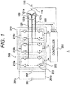
- FIG. 1 is a view illustrating a schematic configuration of a motor system 1 to drive a six-wire three-phase motor.
- the motor system 1 includes an inverter device 200, and a motor 100 driven by the inverter device 200. Note that a DC power supply 201 may be included or may not be included in the motor system 1.
- the inverter device 200 can drive the motor 100 by independently controlling current flowing in armature winding wires 121a to 121c.
- a magnetic pole position detector 115 to detect a magnetic pole position ⁇ of the motor 100 is attached to an output shaft 113 of the motor 100.
- a result of the detection of the magnetic pole position ⁇ by the magnetic pole position detector 115 is output to a controller 203.
- the DC power supply 201 supplies DC power to an inverter circuit 210 through DC buses 201a and 201b.
- a secondary battery such as a lithium-ion battery can be used as the DC power supply 201.
- a smoothing capacitor 202 is to control a variation in a DC voltage, which variation is caused along with an operation of the inverter circuit 210, and is connected in parallel with the inverter circuit 210 between the DC bus 201a and the DC bus 201b.
- the inverter circuit 210 includes full-bridge bridge circuits 210a, 210b, and 210c respectively corresponding to a U phase, a V phase, and a W phase.
- the controller 203 respectively outputs drive signals Gu, Gv, and Gw to the bridge circuits 210a, 210b, and 210c of the inverter circuit 210 and controls the inverter circuit 210 by respectively operating the bridge circuits 210a, 210b, and 210c.
- Each of the bridge circuits 210a, 210b, and 210c includes four IGBTs 221 that function as switching elements of upper and lower arms, and four diodes 222 provided in parallel with the IGBTs 221.
- each of the IGBTs 221 performs a switching operation according to the drive signals Gu, Gv, and Gw from the controller 203. Accordingly, the DC power supplied from the DC power supply 201 is converted into three-phase AC power and is output from the bridge circuits 210a, 210b, and 210c respectively to the armature winding wires 121a, 121b, and 121c in phases of the motor 100 through AC output lines 120 in the phases. Currents iu, iv, and iw flowing in the AC output lines 120 are detected by a current sensor 130 and a detection result thereof is input into the controller 203.
- FIG. 2 is a view illustrating a configuration example of the motor 100 and illustrating a two-pole motor as an example.
- the motor 100 is a magnet-embedded motor.
- the armature winding wires 121a, 121b, and 121c are attached to a stator core 110a of a stator 110 with a phase difference of an electrical angle 120°.
- a rotor core 114 in an inner part of which a plurality of permanent magnets 112 is embedded is fixed to an output shaft 113 of a rotor 111.
- the motor 100 is a six-wire three-phase motor.
- sinusoidal modulation is performed when a motor output is low and a load is light, and a third harmonic is superimposed on a PWM signal wave and an applied voltage is increased when a motor output is high and a load is heavy.
- FIG. 3 is a graph illustrating a generation method of a PWM pulse.
- sinusoidal modulation illustrated in FIG. 3(a)
- signal waves S1 and S2 are applied to a carrier wave C and a PWM pulse is generated.
- overmodulation control illustrated in FIG. 3(b)
- signal waves S3 and S4 including a third harmonic component are applied and a PWM pulse is generated. Note that in FIG. 3 , one phase is illustrated and a signal wave in each phase is what has a phase deviated for 120°.
- amplitude of a fundamental wave is higher than amplitude of a carrier wave and is set in such a manner that a modulation rate > 1.
- an output becomes higher than that in a case of the sinusoidal modulation illustrated in FIG. 3(a) .
- a third harmonic component is included in such a manner that amplitude of the signal waves S3 and S4 becomes lower than the amplitude of the carrier wave.
- a signal wave that has amplitude equal to or lower than the amplitude of the carrier wave and that is illustrated in FIG. 3(b) can be generated.
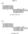
- FIG. 4 is a graph illustrating an inverter applied voltage waveform of a case where the sinusoidal modulation and the overmodulation control in FIG. 3 are performed.
- FIG. 4(a) a case of sinusoidal modulation with a modulation rate being equal to or lower than 1 is illustrated.
- FIG. 4(b) a case of overmodulation control in which a third harmonic is superimposed to make a modulation rate equal to or higher than 1 is illustrated.
- the modulation rate is equal to or higher than 1 in the overmodulation control, it is possible to output voltage without making a switching element being constantly on by superimposing a third harmonic and controlling a maximum value of a signal wave as illustrated in FIG. 3(b) .
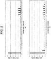
- FIG. 5 an analysis result of a component included in an inverter applied voltage illustrated in FIG. 4 is illustrated.
- a case of sinusoidal modulation is illustrated in FIG. 5(a) and a case of overmodulation is illustrated in FIG. 5(b) .
- amplitude of the carrier wave C and amplitude of the signal wave S1 and S2 are the same.
- amplitude of a fundamental wave (first) component of voltage becomes the same with that of a DC voltage.
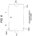
- Equation (1) Current flowing in a motor is determined on the basis of a voltage equation expressed by the following equation (1).
- the equation (1) expresses a U-phase equivalent circuit illustrated in FIG. 6 . Similar equations can be established with respect to a V phase and a W phase.
- Vu is an inverter applied voltage
- Iu current flowing in a motor
- R coil resistance of the motor
- L inductance of the motor
- Eu is an induced voltage by a magnetic flux of the permanent magnets 112 provided in the rotor 111.
- V u RI u + L dI u dt + E u
- FIG. 6 an equivalent circuit of a case where a U-phase bridge circuit 210a and a motor U-phase armature winding wire 121a are connected at U-phase winding wire ends 122a1 and 122a2 is illustrated.
- a third harmonic component is included in at least one of the inverter applied voltage Vu and the induced voltage Eu.
- a third harmonic is also included in the motor current Iu.
- each of the armature winding wires 121a, 121b, and 121c in the phases is independent in the six-wire three-phase motor as illustrated in FIG. 1 , a third harmonic is included in currents Iu, Iv, and Iw flowing in the motor when a third harmonic is included in induced voltages Eu, Ev, Ew or inverter applied voltages Vu, Vv, and Vw as described above.
- E u E 1 sin ⁇ t + E 3 sin 3 ⁇ t + E 5 sin 5 ⁇ t + E 7 sin 7 ⁇ t
- E v E 1 sin ⁇ t ⁇ 120 + E 3 sin 3 ⁇ ⁇ t ⁇ 120 + E 5 sin 5 ⁇ ⁇ t ⁇ 120 + E 7 sin 7 ⁇ ⁇ t ⁇ 120
- E w E 1 sin ⁇ t + 120 + E 3 sin 3 ⁇ ⁇ t + 120 + E 5 sin 5 ⁇ ⁇ t + 120 + E 7 sin 7 ⁇ ⁇ t + 120
- Iu, Iv, and Iw are expressed by the following equations (5) to (7).
- I u I 1 sin ⁇ t + ⁇ + I 3 sin 3 ⁇ ⁇ t + ⁇
- I v I 1 sin ⁇ t ⁇ 120 + ⁇ + I 3 sin 3 ⁇ ⁇ t ⁇ 120 + ⁇
- I w I 1 sin ⁇ t + 120 + ⁇ + I 3 sin 3 ⁇ ⁇ t + 120 + ⁇
- Three items in ⁇ ⁇ of the equations (12) and (13) are sextuple pulsating components by a fifth harmonic induced voltage E5 and a fundamental wave current I1
- four items are sextuple pulsating components by a seventh harmonic induced voltage E7 and the fundamental wave current I1
- five components are sextuple pulsating components by a third harmonic induced voltage E 3 and a third harmonic current I 3 .
- a torque ripple is increased when a third harmonic is included in each of the induced voltages Eu, Ev, and Ew and the current Iu, Iv, and Iw flowing in the motor.
- a torque ripple due to the third harmonic induced voltage E 3 is controlled with a configuration of a winding wire being a configuration described in the following.
- whether a harmonic component is included in the induced voltages Eu, Ev, and Ew depends on a magnetic flux density distribution formed in a gap by the permanent magnets 112.
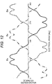
- FIG. 8 is a view for describing generation of a third harmonic induced voltage E 3 (Eu3, Ev3, and Ew3).
- armature winding wires 121a, 121b, and 121c are wound by distributed winding at the same pitch with a magnetic pole pitch of a north pole and a south pole of the permanent magnet 112.
- a line L11 indicates a fundamental wave component of a magnetic flux density distribution, and one cycle thereof is 360° at an electrical angle. This fundamental wave component is a component converted into steady torque or a machine output of a motor.
- a line L13 indicates a third harmonic component in the magnetic flux density distribution, and one cycle thereof is 120° at the electrical angle. In such a manner, the north pole and the south pole are lined up at equal intervals at a pitch of 180°. However, the magnetic flux density distribution is not sinusoidal but is distorted.
- a pitch (electrical angle 180°) of the U-phase armature winding wire 121a corresponds to 1.5 cycles of a third harmonic component.
- Induced voltage Eu is generated when a magnetic flux is interlinked with the U-phase armature winding wire 121a.
- Magnitude or a direction of the induced voltage Eu in the U-phase armature winding wire 121a varies depending on a phase of the interlinked magnetic flux.
- a plus part in a half cycle remains as an interlinkage magnetic flux when a rotor 111 is rotated for 60° (electrical angle) from the state in FIG. 8 , and a state goes back to that in FIG. 8 with a further rotation for 60° (electrical angle).
- an induced voltage component in a cycle 120° that is, the third harmonic induced voltage Eu3 is generated.
- the third harmonic induced voltages EV3 and Ew3 in a V phase and a W phase are in a similar manner.
- FIG. 9 is a view for describing a stator structure in the present embodiment. With a winding wire configuration illustrated in FIG. 9 , it is possible to control generation of a torque ripple due to a third harmonic voltage even in a case where the third harmonic voltage is superimposed on an inverter applied voltage and high-output driving is performed.
- winding is performed by 2/3 short pitch winding in which a pitch of armature winding wires 121a, 121b, and 121c is 2/3 of a magnetic pole pitch.
- a pitch of the winding wires is an electrical angle 120° and is set to be the same with one cycle of a third harmonic component in a magnetic flux density distribution.
- one cycle of a third harmonic component is constantly included in a range of the electrical angle 120°, and a plus part and a minus part constantly cancel each other.
- the armature winding wires 121a, 121b, and 121c in phases are wound in such a manner that a third harmonic component in the magnetic flux density distribution is not interlinked with the armature winding wires 121a, 121b, and 121c in the phases.
- FIG. 10 a two-pole three-slot concentrated winding stator is illustrated.
- armature winding wires 121a, 121b, and 121c in phases are arranged at intervals of an electrical angle 120° in one cycle of a magnetic pole (electrical angle 360°) .
- a hatched region in a line L13 indicating a third harmonic component in a magnetic flux density distribution is seen, it is understood that a plus part and a minus part cancel each other in a range of the electrical angle 120°.
- a term including E 3 in the equation (13) becomes zero.
- FIG. 11 is a view of a case where the number of slots per pole per phase is 2 and illustrating a case where the present embodiment is not applied.
- a phase belt 122 of a U phase is arranged at an electrical angle 180 pitch.
- Phase belts of a V phase and a W phase are similar to a case of the U phase.
- An arrangement of the phase belt 122 is the same with an arrangement in a case of (U+) and (U-) in FIG. 8 . From a reason similar to that in a case of FIG. 8 , a third harmonic induced voltage due to a third harmonic component in a magnetic flux density distribution is generated.
- FIG. 13 is a graph illustrating a component in each order in an induced voltage.
- the induced voltage includes a low-order harmonic component including a third harmonic.
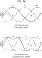
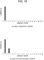
- FIG. 16 is a graph illustrating a component in a current waveform illustrated in FIG. 14 .
- FIG. 14(a) a case where currents Iu, Iv, and Iw are a sinusoidal current is illustrated. In this case, only a first fundamental wave component is included as illustrated in FIG. 16(a) .
- currents Iu, Iv, and Iw illustrated in FIG. 14(b) indicate a case of a distortion wave current including a fundamental wave component and a third harmonic component.
- a fundamental wave component and a third harmonic component are included.
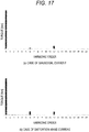
- FIG. 17 is a graph illustrating a component included in the torque waveform in FIG. 15 .
- a component in the torque waveform in FIG. 15(a) is illustrated in FIG. 17(a)
- a component in the torque waveform in FIG. 15(b) is illustrated in FIG. 17(b) .
- Average torque does not vary much in a case of FIG. 17(a) and a case of FIG. 17(b) . It is understood that a torque ripple is higher in the case of FIG. 17(b) in which a distortion wave current including a third harmonic flows.
- a third term and a fourth term in ⁇ ⁇ in the equation (13) appear as a sixth component in a case where a sinusoidal current flows
- a third term, a fourth term, and a fifth term in ⁇ ⁇ in the equation (13) appear as a sixth component in a case where a distortion wave current including a third harmonic flows.
- the torque ripple becomes higher in the case of FIG. 17(b) since the fifth term is included.
- a winding wire configuration illustrated in FIG. 18 is employed instead of the winding wire configuration in FIG. 11 . That is, an arrangement of a phase belt 122 is similar to the arrangement illustrated in FIG. 9 , and 2/3 short pitch winding in which a pitch of the phase belt 122 is an electrical angle 120° is employed. With such a winding wire configuration, a third harmonic induced voltage E 3 becomes zero and a fifth term including E 3 in the equation (13) becomes zero, whereby it is possible to reduce a sixth component in a torque ripple.
- FIG. 19 is a graph illustrating an example of an induced voltage waveform generated in an armature winding wire in each phase in a case of a stator structure illustrated in FIG. 18 . It is understood that an induced voltage in each phase is not sinusoidal but a distorted wave.
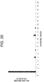
- FIG. 20 a component in each order in the induced voltage waveform illustrated in FIG. 19 is illustrated. It can be understood that a low-order harmonic component is included in the induced voltage waveform but no third harmonic component is included since a pitch of the phase belt 122 is set to the electrical angle 120°.
- FIG. 21 a torque waveform of a case where the currents illustrated in FIG. 14 flow in a motor having a stator configuration illustrated in FIG. 18 is illustrated.
- FIG. 22 is a graph illustrating each order component in the torque waveform illustrated in FIG. 21 .
- FIG. 21(a) a torque waveform in a case of the sinusoidal current in FIG. 14(a) is illustrated.
- FIG. 21(b) a torque waveform in a case of the distortion wave current in FIG. 14(b) is illustrated.
- the both torque waveforms are substantially the same.
- FIGS. 22(a) and (b) it is understood that components in the same order are included in both of a case where the sinusoidal current flows and a case where the distortion wave current flows and that magnitude of the components in the same order is substantially the same.
- an inverter voltage including a third harmonic voltage is applied to a motor to increase an output in a six-wire three-phase motor, it is possible to prevent generation of a torque ripple due to the third harmonic voltage and to realize low vibration and small noise while increasing the output.
- a third harmonic current component in a motor current of when an overmodulation voltage based on a PWM signal is applied is higher than a third harmonic current component in a motor current of when a sinusoidal modulation voltage based on the PWM signal is applied.
- the signal wave includes a fundamental wave having amplitude higher than amplitude of the carrier wave and a third harmonic signal and has amplitude equal to or lower than the amplitude of the carrier wave.
- a third harmonic current is preferably as low as possible in order to control a copper loss due to the third harmonic current.
- magnitude of a third harmonic superimposed on the signal wave can be selected freely.
- a motor illustrated in FIG. 9 is a six-wire three-phase motor including: a stator including a winding wire wound independently between phases; and a rotor including a plurality of magnets in a circumferential direction, wherein the winding wire is wound by distributed winding, in which a pitch of the winding wire becomes 2/3, and is configured in such a manner that a third harmonic current component in a motor current of when an overmodulation voltage based on a PWM signal is applied becomes higher than a third harmonic current component in a motor current of when a sinusoidal modulation voltage based on the PWM signal is applied.
- a third harmonic current component in a motor current of when an overmodulation voltage based on a PWM signal is applied becomes higher than a third harmonic current component in a motor current of when a sinusoidal modulation voltage based on the PWM signal is applied.
- a motor illustrated in FIG. 10 is a six-wire three-phase motor including: a stator including a winding wire wound independently between phases; and a rotor including a plurality of magnets in a circumferential direction, wherein the winding wire is wound by two-pole three-slot or four-pole three-slot concentrated winding and is configured in such a manner that a third harmonic current component in a motor current of when an overmodulation voltage based on a PWM signal is applied becomes higher than a third harmonic current component in a motor current of when a sinusoidal modulation voltage based on the PWM signal is applied.
- a third harmonic current component in a motor current of when an overmodulation voltage based on a PWM signal is applied becomes higher than a third harmonic current component in a motor current of when a sinusoidal modulation voltage based on the PWM signal is applied.
- a third harmonic induced voltage E 3 is reduced and a torque ripple due to I 3 and E 3 is controlled with a contrivance in a structure on a side of a rotor.
- FIG. 23 is a view for describing a rotor structure in the second embodiment.
- a stator structure is similar to a stator structure of the motor illustrated in FIG. 8 , and a winding wire is wound by distributed winding at an electrical angle 180°.
- a third harmonic current I 3 flows in the motor due to the third harmonic included in the inverter applied voltage, a torque ripple is increased and vibration or noise is increased.
- a ratio between the angle ⁇ and an electrical angle 180° of a magnetic pole pitch ( ⁇ /180) is called a pole-arc ratio.
- a part 114a of a rotor core 114 between two adjacent permanent magnets 112 is called an auxiliary magnetic pole.
- a distribution of magnetic flux density formed in a gap between the rotor 111 and a stator 110 is determined according to the permanent magnet 112 and the auxiliary magnetic pole 114a. That is, the magnetic flux density distribution depends on the pole-arc ratio.
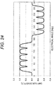
- FIG. 24 is a graph illustrating an example of a distribution of gap flux density (magnetic flux density in gap). It is understood that the gap flux density is not sinusoidal and includes a harmonic due to an influence of a shape of the permanent magnet 112 or a slot in which an armature winding wire is provided.
- FIG. 25(a) is a graph illustrating how a fundamental wave (first) component and a third harmonic component included in a gap flux density distribution vary according to a pole-arc ratio, a horizontal axis indicating the pole-arc ratio.
- FIG. 25(b) is a graph illustrating a relationship between an induced voltage (no-load induced voltage) and a pole-arc ratio.
- Each of lines L21 and L31 indicates a fundamental wave component and each of lines L23 and L33 indicates a third harmonic component.
- a third harmonic induced voltage E 3 substantially zero.
- a third harmonic current is not generated in a motor current in a case where an inverter applied voltage by sinusoidal modulation is applied
- a third harmonic current corresponding to a third harmonic component V 3 of an inverter applied voltage is generated in a case where the inverter applied voltage by overmodulation is applied. That is, a third harmonic current component in a motor current of when an overmodulation voltage based on a PWM signal is applied is higher than a third harmonic current component in a motor current of when a sinusoidal modulation voltage based on the PWM signal is applied.
- a distribution of gap flux density generated by the permanent magnet 112 provided in the rotor core 114 can be changed according to a shape, the number, and an arrangement of permanent magnets 112, including the above-described pole-arc ratio. Then, by changing these and making a third harmonic component in a magnetic flux density distribution, it is possible to prevent a third harmonic component from being included in an induced voltage.
- An element (parameter) to determine a distribution of gap flux density is not limited to a shape, the number, or an arrangement of permanent magnets 112. Then, by adjusting a parameter to determine a distribution of gap flux density, it is possible to prevent a third harmonic component from being included in an induced voltage.
- a motor of the second embodiment is summarized as follows.
- a motor configured in a manner illustrated in FIG. 23 and FIG. 25 is a six-wire three-phase motor including: a stator including a winding wire wound independently between phases; and a rotor including a plurality of magnets in a circumferential direction, wherein the rotor is configured in such a manner that a pole-arc ratio of the magnets is 2/3 and a third harmonic current component in a motor current of when an overmodulation voltage based on a PWM signal is applied becomes higher than a third harmonic current component in a motor current of when a sinusoidal modulation voltage based on the PWM signal is applied.
- a third harmonic current component in a motor current of when an overmodulation voltage based on a PWM signal is applied becomes higher than a third harmonic current component in a motor current of when a sinusoidal modulation voltage based on the PWM signal is applied.
- a stator structure is similar to that in a case of FIG. 8 . Even with such a stator structure, a third harmonic component is prevented from being included in an induced voltage with a contrivance in a pole-arc ratio on a side of a rotor.
- a stator structure of the first embodiment may be employed and a rotor configuration of the second embodiment may be further applied.
Landscapes
- Engineering & Computer Science (AREA)
- Power Engineering (AREA)
- Control Of Motors That Do Not Use Commutators (AREA)
- Control Of Ac Motors In General (AREA)
- Permanent Magnet Type Synchronous Machine (AREA)
Claims (5)
- Sechsleiter-Drehstrommotor, der Folgendes umfasst:- einen Stator (110), der einen Wickeldraht enthält, der zwischen den Phasen unabhängig gewickelt ist; und- einen Rotor (111), der in einer Umfangsrichtung mehrere Magneten enthält,dadurch gekennzeichnet, dass der Stator (110) oder der Rotor (111) derart konfiguriert ist, dass dann, wenn eine Übermodulationsspannung basierend auf einem PWM-Signal angelegt wird, eine dritte harmonische Stromkomponente in einem Motorstrom höher wird als eine dritte harmonische Stromkomponente in einem Motorstrom, wenn eine sinusförmige Modulationsspannung basierend auf dem PWM-Signal angelegt wird,
wobei eine induzierte Spannung, die in dem Wickeldraht aufgrund der mehreren Magneten erzeugt wird, keine dritte harmonische Komponente enthält, falls ein Pol/Bogen-Verhältnis der Magneten 2/3 ist. - Sechsleiter-Drehstrommotor nach Anspruch 1,
wobei der Wickeldraht derart gewickelt ist, dass in der induzierten Spannung, die aufgrund der Magneten erzeugt worden ist, keine dritte harmonische Komponente enthalten ist. - Sechsleiter-Drehstrommotor nach Anspruch 2,
wobei der Wickeldraht ein Wickeldraht ist, der durch konzentrierte Zweipol-Dreiloch- oder Vierpol-Dreiloch-Wicklung gewickelt ist. - Sechsleiter-Drehstrommotor nach Anspruch 2,
wobei der Wickeldraht durch verteiltes Wickeln, bei dem eine Teilung des Wickeldrahts 2/3 wird, gewickelt ist. - Motorsystem, das Folgendes umfasst:den Sechsleiter-Drehstrommotor nach Anspruch 1; undeine Wechselrichtervorrichtung, die durch PWM-Steuerung basierend auf einer Trägerwelle eine am Wechselrichter angelegte Spannung und eine Signalwelle an den Sechsleiter-Drehstrommotor anlegt,wobei die Signalwelle eine Grundwelle, deren Amplitude höher als die Amplitude der Trägerwelle und eines dritten harmonischen Signals ist, enthält und eine Amplitude aufweist, die kleiner oder gleich der Amplitude der Trägerwelle ist.
Applications Claiming Priority (2)
| Application Number | Priority Date | Filing Date | Title |
|---|---|---|---|
| JP2016133460 | 2016-07-05 | ||
| PCT/JP2017/022452 WO2018008372A1 (ja) | 2016-07-05 | 2017-06-19 | 6線3相モータ、インバータ装置およびモータシステム |
Publications (4)
| Publication Number | Publication Date |
|---|---|
| EP3484044A1 EP3484044A1 (de) | 2019-05-15 |
| EP3484044A4 EP3484044A4 (de) | 2020-03-04 |
| EP3484044B1 true EP3484044B1 (de) | 2021-09-01 |
| EP3484044B8 EP3484044B8 (de) | 2021-10-06 |
Family
ID=60912699
Family Applications (1)
| Application Number | Title | Priority Date | Filing Date |
|---|---|---|---|
| EP17823979.4A Active EP3484044B8 (de) | 2016-07-05 | 2017-06-19 | 6-draht 3-phasendrehstrommotor |
Country Status (5)
| Country | Link |
|---|---|
| US (1) | US10868488B2 (de) |
| EP (1) | EP3484044B8 (de) |
| JP (1) | JP6626973B2 (de) |
| CN (1) | CN109451783B (de) |
| WO (1) | WO2018008372A1 (de) |
Families Citing this family (4)
| Publication number | Priority date | Publication date | Assignee | Title |
|---|---|---|---|---|
| KR102697977B1 (ko) * | 2019-09-09 | 2024-08-22 | 에스엘 주식회사 | 차량용 변속 장치 |
| US11362605B2 (en) * | 2020-01-29 | 2022-06-14 | Semiconductor Components Industries, Llc | Drive methods for a three-phase motor |
| US11456680B2 (en) | 2020-05-08 | 2022-09-27 | Hamilton Sundstrand Corporation | Over-modulation pulse width modulation with maximum output and minimum harmonics |
| JP6991298B1 (ja) * | 2020-10-21 | 2022-01-12 | 三菱電機株式会社 | 電流検出装置 |
Family Cites Families (18)
| Publication number | Priority date | Publication date | Assignee | Title |
|---|---|---|---|---|
| US6058031A (en) * | 1997-10-23 | 2000-05-02 | General Electric Company | Five level high power motor drive converter and control system |
| US6005783A (en) * | 1998-06-26 | 1999-12-21 | General Motors Corporation | Method of synthesizing poly-phase AC voltage |
| JP2000125411A (ja) | 1998-10-13 | 2000-04-28 | Toyota Motor Corp | モータ駆動装置 |
| JP3638944B1 (ja) * | 2004-02-04 | 2005-04-13 | 山洋電気株式会社 | 永久磁石内蔵型回転モータの極弧率の決定方法及び永久磁石内蔵型回転モータ |
| JP2006160030A (ja) * | 2004-12-06 | 2006-06-22 | Nsk Ltd | 電動パワーステアリング装置 |
| JP5120586B2 (ja) * | 2005-06-28 | 2013-01-16 | 株式会社デンソー | 界磁巻線型同期機 |
| JP4804381B2 (ja) * | 2007-02-28 | 2011-11-02 | 三菱電機株式会社 | 電動機駆動制御装置及び電動機 |
| JP5002343B2 (ja) * | 2007-06-18 | 2012-08-15 | 株式会社豊田中央研究所 | 交流電動機の駆動制御装置 |
| JP2009071910A (ja) * | 2007-09-11 | 2009-04-02 | Hitachi Ltd | 回転電機およびそれを搭載した自動車 |
| JP5337382B2 (ja) * | 2008-01-21 | 2013-11-06 | 株式会社日立産機システム | 永久磁石式同期モータ |
| JP2009219331A (ja) * | 2008-03-13 | 2009-09-24 | Hitachi Ltd | 永久磁石式ジェネレータとそれを用いたハイブリッド車両 |
| JP5369630B2 (ja) * | 2008-11-12 | 2013-12-18 | トヨタ自動車株式会社 | 交流電動機の制御装置 |
| JP5723524B2 (ja) * | 2009-11-06 | 2015-05-27 | 日立オートモティブシステムズ株式会社 | 回転電機及び電気自動車 |
| US8742712B2 (en) * | 2011-01-26 | 2014-06-03 | GM Global Technology Operations LLC | Methods, systems and apparatus for controlling third harmonic voltage when operating a multi-phase machine in an overmodulation region |
| JP5626592B2 (ja) * | 2011-08-08 | 2014-11-19 | アイシン・エィ・ダブリュ株式会社 | 制御装置 |
| MX2014003618A (es) * | 2011-09-30 | 2014-06-23 | Mitsubishi Electric Corp | Dispositivo y metodo de control para motor electrico, y sistema de accionamiento de vehiculo y motor en el cual el dispositivo y metodo de control son aplicados. |
| JP2014131373A (ja) * | 2012-12-28 | 2014-07-10 | Hitachi Appliances Inc | 永久磁石同期機 |
| WO2015104795A1 (ja) * | 2014-01-08 | 2015-07-16 | 株式会社日立製作所 | 回転電機 |
-
2017
- 2017-06-19 EP EP17823979.4A patent/EP3484044B8/de active Active
- 2017-06-19 CN CN201780034959.9A patent/CN109451783B/zh active Active
- 2017-06-19 JP JP2018526001A patent/JP6626973B2/ja active Active
- 2017-06-19 US US16/309,642 patent/US10868488B2/en active Active
- 2017-06-19 WO PCT/JP2017/022452 patent/WO2018008372A1/ja not_active Ceased
Non-Patent Citations (1)
| Title |
|---|
| None * |
Also Published As
| Publication number | Publication date |
|---|---|
| JPWO2018008372A1 (ja) | 2019-02-21 |
| EP3484044A4 (de) | 2020-03-04 |
| EP3484044A1 (de) | 2019-05-15 |
| US10868488B2 (en) | 2020-12-15 |
| EP3484044B8 (de) | 2021-10-06 |
| US20190165715A1 (en) | 2019-05-30 |
| CN109451783A (zh) | 2019-03-08 |
| WO2018008372A1 (ja) | 2018-01-11 |
| CN109451783B (zh) | 2022-03-11 |
| JP6626973B2 (ja) | 2019-12-25 |
Similar Documents
| Publication | Publication Date | Title |
|---|---|---|
| US9083276B2 (en) | Rotary electric machine driving system | |
| US8497648B2 (en) | Synchronous electric motor drive system | |
| US20130334937A1 (en) | Rotary electric machine driving system | |
| EP3364538B1 (de) | Drehmaschinensteuerungsvorrichtung und elektrische servolenkungsvorrichtung damit | |
| US9985559B2 (en) | Control apparatus for rotating machine | |
| EP3163743B1 (de) | Motorantriebsvorrichtung | |
| EP3570431A1 (de) | Motor und steuerungsvorrichtung dafür | |
| JP4032516B2 (ja) | 自動車用電動駆動装置 | |
| US9553530B2 (en) | Power converter | |
| US11283385B2 (en) | Motor system provided with both motor having multiple-phase stator windings and control device controlling the motor | |
| US8742710B2 (en) | Rotary electric machine system | |
| EP3484044B1 (de) | 6-draht 3-phasendrehstrommotor | |
| US11283384B2 (en) | Motor system provided with both motor having multiple-phase stator windings and control device controlling the motor | |
| WO2017141513A1 (ja) | 電力変換装置 | |
| US8664902B2 (en) | Polyphase AC motor, driving device and driving method therefor | |
| US9214882B2 (en) | Control device and method for determining the rotor angle of a synchronous machine | |
| US9178455B2 (en) | Control device and method for determining the rotor angle of a synchronous machine | |
| US12199539B2 (en) | Motor control device, electric vehicle, and motor control method | |
| JP6075161B2 (ja) | スイッチトリラクタンスモータの制御装置 | |
| EP3206297B1 (de) | Stromumwandlungsvorrichtung und steuerungsverfahren dafür und steuerungsvorrichtung für elektrische servolenkung | |
| US10526007B2 (en) | Power conversion device, control method for same, and electric power steering control device | |
| CN112292810A (zh) | 马达控制装置 |
Legal Events
| Date | Code | Title | Description |
|---|---|---|---|
| STAA | Information on the status of an ep patent application or granted ep patent |
Free format text: STATUS: THE INTERNATIONAL PUBLICATION HAS BEEN MADE |
|
| PUAI | Public reference made under article 153(3) epc to a published international application that has entered the european phase |
Free format text: ORIGINAL CODE: 0009012 |
|
| STAA | Information on the status of an ep patent application or granted ep patent |
Free format text: STATUS: REQUEST FOR EXAMINATION WAS MADE |
|
| 17P | Request for examination filed |
Effective date: 20190205 |
|
| AK | Designated contracting states |
Kind code of ref document: A1 Designated state(s): AL AT BE BG CH CY CZ DE DK EE ES FI FR GB GR HR HU IE IS IT LI LT LU LV MC MK MT NL NO PL PT RO RS SE SI SK SM TR |
|
| AX | Request for extension of the european patent |
Extension state: BA ME |
|
| DAV | Request for validation of the european patent (deleted) | ||
| DAX | Request for extension of the european patent (deleted) | ||
| A4 | Supplementary search report drawn up and despatched |
Effective date: 20200204 |
|
| RIC1 | Information provided on ipc code assigned before grant |
Ipc: H02M 7/48 20070101ALI20200129BHEP Ipc: H02P 6/10 20060101ALI20200129BHEP Ipc: H02P 27/08 20060101AFI20200129BHEP |
|
| STAA | Information on the status of an ep patent application or granted ep patent |
Free format text: STATUS: EXAMINATION IS IN PROGRESS |
|
| 17Q | First examination report despatched |
Effective date: 20201002 |
|
| GRAP | Despatch of communication of intention to grant a patent |
Free format text: ORIGINAL CODE: EPIDOSNIGR1 |
|
| STAA | Information on the status of an ep patent application or granted ep patent |
Free format text: STATUS: GRANT OF PATENT IS INTENDED |
|
| INTG | Intention to grant announced |
Effective date: 20210316 |
|
| GRAS | Grant fee paid |
Free format text: ORIGINAL CODE: EPIDOSNIGR3 |
|
| GRAA | (expected) grant |
Free format text: ORIGINAL CODE: 0009210 |
|
| STAA | Information on the status of an ep patent application or granted ep patent |
Free format text: STATUS: THE PATENT HAS BEEN GRANTED |
|
| AK | Designated contracting states |
Kind code of ref document: B1 Designated state(s): AL AT BE BG CH CY CZ DE DK EE ES FI FR GB GR HR HU IE IS IT LI LT LU LV MC MK MT NL NO PL PT RO RS SE SI SK SM TR |
|
| REG | Reference to a national code |
Ref country code: GB Ref legal event code: FG4D |
|
| REG | Reference to a national code |
Ref country code: DE Ref legal event code: R081 Ref document number: 602017045344 Country of ref document: DE Owner name: HITACHI ASTEMO, LTD., HITACHINAKA-SHI, JP Free format text: FORMER OWNER: HITACHI AUTOMOTIVE SYSTEMS, LTD., HITACHINAKA-SHI, IBARAKI, JP |
|
| REG | Reference to a national code |
Ref country code: AT Ref legal event code: REF Ref document number: 1427295 Country of ref document: AT Kind code of ref document: T Effective date: 20210915 Ref country code: CH Ref legal event code: PK Free format text: BERICHTIGUNG B8 Ref country code: CH Ref legal event code: EP |
|
| REG | Reference to a national code |
Ref country code: DE Ref legal event code: R096 Ref document number: 602017045344 Country of ref document: DE |
|
| RAP4 | Party data changed (patent owner data changed or rights of a patent transferred) |
Owner name: HITACHI ASTEMO, LTD. |
|
| REG | Reference to a national code |
Ref country code: IE Ref legal event code: FG4D |
|
| REG | Reference to a national code |
Ref country code: LT Ref legal event code: MG9D |
|
| REG | Reference to a national code |
Ref country code: NL Ref legal event code: MP Effective date: 20210901 |
|
| PG25 | Lapsed in a contracting state [announced via postgrant information from national office to epo] |
Ref country code: NO Free format text: LAPSE BECAUSE OF FAILURE TO SUBMIT A TRANSLATION OF THE DESCRIPTION OR TO PAY THE FEE WITHIN THE PRESCRIBED TIME-LIMIT Effective date: 20211201 Ref country code: LT Free format text: LAPSE BECAUSE OF FAILURE TO SUBMIT A TRANSLATION OF THE DESCRIPTION OR TO PAY THE FEE WITHIN THE PRESCRIBED TIME-LIMIT Effective date: 20210901 Ref country code: BG Free format text: LAPSE BECAUSE OF FAILURE TO SUBMIT A TRANSLATION OF THE DESCRIPTION OR TO PAY THE FEE WITHIN THE PRESCRIBED TIME-LIMIT Effective date: 20211201 Ref country code: RS Free format text: LAPSE BECAUSE OF FAILURE TO SUBMIT A TRANSLATION OF THE DESCRIPTION OR TO PAY THE FEE WITHIN THE PRESCRIBED TIME-LIMIT Effective date: 20210901 Ref country code: SE Free format text: LAPSE BECAUSE OF FAILURE TO SUBMIT A TRANSLATION OF THE DESCRIPTION OR TO PAY THE FEE WITHIN THE PRESCRIBED TIME-LIMIT Effective date: 20210901 Ref country code: HR Free format text: LAPSE BECAUSE OF FAILURE TO SUBMIT A TRANSLATION OF THE DESCRIPTION OR TO PAY THE FEE WITHIN THE PRESCRIBED TIME-LIMIT Effective date: 20210901 Ref country code: FI Free format text: LAPSE BECAUSE OF FAILURE TO SUBMIT A TRANSLATION OF THE DESCRIPTION OR TO PAY THE FEE WITHIN THE PRESCRIBED TIME-LIMIT Effective date: 20210901 Ref country code: ES Free format text: LAPSE BECAUSE OF FAILURE TO SUBMIT A TRANSLATION OF THE DESCRIPTION OR TO PAY THE FEE WITHIN THE PRESCRIBED TIME-LIMIT Effective date: 20210901 |
|
| REG | Reference to a national code |
Ref country code: AT Ref legal event code: MK05 Ref document number: 1427295 Country of ref document: AT Kind code of ref document: T Effective date: 20210901 |
|
| PG25 | Lapsed in a contracting state [announced via postgrant information from national office to epo] |
Ref country code: PL Free format text: LAPSE BECAUSE OF FAILURE TO SUBMIT A TRANSLATION OF THE DESCRIPTION OR TO PAY THE FEE WITHIN THE PRESCRIBED TIME-LIMIT Effective date: 20210901 Ref country code: LV Free format text: LAPSE BECAUSE OF FAILURE TO SUBMIT A TRANSLATION OF THE DESCRIPTION OR TO PAY THE FEE WITHIN THE PRESCRIBED TIME-LIMIT Effective date: 20210901 Ref country code: GR Free format text: LAPSE BECAUSE OF FAILURE TO SUBMIT A TRANSLATION OF THE DESCRIPTION OR TO PAY THE FEE WITHIN THE PRESCRIBED TIME-LIMIT Effective date: 20211202 |
|
| PG25 | Lapsed in a contracting state [announced via postgrant information from national office to epo] |
Ref country code: AT Free format text: LAPSE BECAUSE OF FAILURE TO SUBMIT A TRANSLATION OF THE DESCRIPTION OR TO PAY THE FEE WITHIN THE PRESCRIBED TIME-LIMIT Effective date: 20210901 |
|
| PG25 | Lapsed in a contracting state [announced via postgrant information from national office to epo] |
Ref country code: IS Free format text: LAPSE BECAUSE OF FAILURE TO SUBMIT A TRANSLATION OF THE DESCRIPTION OR TO PAY THE FEE WITHIN THE PRESCRIBED TIME-LIMIT Effective date: 20220101 Ref country code: SM Free format text: LAPSE BECAUSE OF FAILURE TO SUBMIT A TRANSLATION OF THE DESCRIPTION OR TO PAY THE FEE WITHIN THE PRESCRIBED TIME-LIMIT Effective date: 20210901 Ref country code: SK Free format text: LAPSE BECAUSE OF FAILURE TO SUBMIT A TRANSLATION OF THE DESCRIPTION OR TO PAY THE FEE WITHIN THE PRESCRIBED TIME-LIMIT Effective date: 20210901 Ref country code: RO Free format text: LAPSE BECAUSE OF FAILURE TO SUBMIT A TRANSLATION OF THE DESCRIPTION OR TO PAY THE FEE WITHIN THE PRESCRIBED TIME-LIMIT Effective date: 20210901 Ref country code: PT Free format text: LAPSE BECAUSE OF FAILURE TO SUBMIT A TRANSLATION OF THE DESCRIPTION OR TO PAY THE FEE WITHIN THE PRESCRIBED TIME-LIMIT Effective date: 20220103 Ref country code: NL Free format text: LAPSE BECAUSE OF FAILURE TO SUBMIT A TRANSLATION OF THE DESCRIPTION OR TO PAY THE FEE WITHIN THE PRESCRIBED TIME-LIMIT Effective date: 20210901 Ref country code: EE Free format text: LAPSE BECAUSE OF FAILURE TO SUBMIT A TRANSLATION OF THE DESCRIPTION OR TO PAY THE FEE WITHIN THE PRESCRIBED TIME-LIMIT Effective date: 20210901 Ref country code: CZ Free format text: LAPSE BECAUSE OF FAILURE TO SUBMIT A TRANSLATION OF THE DESCRIPTION OR TO PAY THE FEE WITHIN THE PRESCRIBED TIME-LIMIT Effective date: 20210901 Ref country code: AL Free format text: LAPSE BECAUSE OF FAILURE TO SUBMIT A TRANSLATION OF THE DESCRIPTION OR TO PAY THE FEE WITHIN THE PRESCRIBED TIME-LIMIT Effective date: 20210901 |
|
| REG | Reference to a national code |
Ref country code: DE Ref legal event code: R097 Ref document number: 602017045344 Country of ref document: DE |
|
| PLBE | No opposition filed within time limit |
Free format text: ORIGINAL CODE: 0009261 |
|
| STAA | Information on the status of an ep patent application or granted ep patent |
Free format text: STATUS: NO OPPOSITION FILED WITHIN TIME LIMIT |
|
| PG25 | Lapsed in a contracting state [announced via postgrant information from national office to epo] |
Ref country code: IT Free format text: LAPSE BECAUSE OF FAILURE TO SUBMIT A TRANSLATION OF THE DESCRIPTION OR TO PAY THE FEE WITHIN THE PRESCRIBED TIME-LIMIT Effective date: 20210901 Ref country code: DK Free format text: LAPSE BECAUSE OF FAILURE TO SUBMIT A TRANSLATION OF THE DESCRIPTION OR TO PAY THE FEE WITHIN THE PRESCRIBED TIME-LIMIT Effective date: 20210901 |
|
| 26N | No opposition filed |
Effective date: 20220602 |
|
| PG25 | Lapsed in a contracting state [announced via postgrant information from national office to epo] |
Ref country code: SI Free format text: LAPSE BECAUSE OF FAILURE TO SUBMIT A TRANSLATION OF THE DESCRIPTION OR TO PAY THE FEE WITHIN THE PRESCRIBED TIME-LIMIT Effective date: 20210901 |
|
| PG25 | Lapsed in a contracting state [announced via postgrant information from national office to epo] |
Ref country code: MC Free format text: LAPSE BECAUSE OF FAILURE TO SUBMIT A TRANSLATION OF THE DESCRIPTION OR TO PAY THE FEE WITHIN THE PRESCRIBED TIME-LIMIT Effective date: 20210901 |
|
| REG | Reference to a national code |
Ref country code: CH Ref legal event code: PL |
|
| REG | Reference to a national code |
Ref country code: BE Ref legal event code: MM Effective date: 20220630 |
|
| GBPC | Gb: european patent ceased through non-payment of renewal fee |
Effective date: 20220619 |
|
| PG25 | Lapsed in a contracting state [announced via postgrant information from national office to epo] |
Ref country code: LU Free format text: LAPSE BECAUSE OF NON-PAYMENT OF DUE FEES Effective date: 20220619 Ref country code: LI Free format text: LAPSE BECAUSE OF NON-PAYMENT OF DUE FEES Effective date: 20220630 Ref country code: IE Free format text: LAPSE BECAUSE OF NON-PAYMENT OF DUE FEES Effective date: 20220619 Ref country code: FR Free format text: LAPSE BECAUSE OF NON-PAYMENT OF DUE FEES Effective date: 20220630 Ref country code: CH Free format text: LAPSE BECAUSE OF NON-PAYMENT OF DUE FEES Effective date: 20220630 |
|
| PG25 | Lapsed in a contracting state [announced via postgrant information from national office to epo] |
Ref country code: GB Free format text: LAPSE BECAUSE OF NON-PAYMENT OF DUE FEES Effective date: 20220619 Ref country code: BE Free format text: LAPSE BECAUSE OF NON-PAYMENT OF DUE FEES Effective date: 20220630 |
|
| PG25 | Lapsed in a contracting state [announced via postgrant information from national office to epo] |
Ref country code: HU Free format text: LAPSE BECAUSE OF FAILURE TO SUBMIT A TRANSLATION OF THE DESCRIPTION OR TO PAY THE FEE WITHIN THE PRESCRIBED TIME-LIMIT; INVALID AB INITIO Effective date: 20170619 |
|
| PG25 | Lapsed in a contracting state [announced via postgrant information from national office to epo] |
Ref country code: MK Free format text: LAPSE BECAUSE OF FAILURE TO SUBMIT A TRANSLATION OF THE DESCRIPTION OR TO PAY THE FEE WITHIN THE PRESCRIBED TIME-LIMIT Effective date: 20210901 Ref country code: CY Free format text: LAPSE BECAUSE OF FAILURE TO SUBMIT A TRANSLATION OF THE DESCRIPTION OR TO PAY THE FEE WITHIN THE PRESCRIBED TIME-LIMIT Effective date: 20210901 |
|
| PG25 | Lapsed in a contracting state [announced via postgrant information from national office to epo] |
Ref country code: MT Free format text: LAPSE BECAUSE OF FAILURE TO SUBMIT A TRANSLATION OF THE DESCRIPTION OR TO PAY THE FEE WITHIN THE PRESCRIBED TIME-LIMIT Effective date: 20210901 |
|
| PGFP | Annual fee paid to national office [announced via postgrant information from national office to epo] |
Ref country code: DE Payment date: 20250429 Year of fee payment: 9 |
|
| PG25 | Lapsed in a contracting state [announced via postgrant information from national office to epo] |
Ref country code: TR Free format text: LAPSE BECAUSE OF FAILURE TO SUBMIT A TRANSLATION OF THE DESCRIPTION OR TO PAY THE FEE WITHIN THE PRESCRIBED TIME-LIMIT Effective date: 20210901 |