EP3484010A1 - Dispositif de traitement d'informations, système de traitement d'informations et procédé de charge - Google Patents
Dispositif de traitement d'informations, système de traitement d'informations et procédé de charge Download PDFInfo
- Publication number
- EP3484010A1 EP3484010A1 EP17827189.6A EP17827189A EP3484010A1 EP 3484010 A1 EP3484010 A1 EP 3484010A1 EP 17827189 A EP17827189 A EP 17827189A EP 3484010 A1 EP3484010 A1 EP 3484010A1
- Authority
- EP
- European Patent Office
- Prior art keywords
- charging
- battery
- charged capacity
- information processing
- processing device
- Prior art date
- Legal status (The legal status is an assumption and is not a legal conclusion. Google has not performed a legal analysis and makes no representation as to the accuracy of the status listed.)
- Pending
Links
- 230000010365 information processing Effects 0.000 title claims abstract description 98
- 238000000034 method Methods 0.000 title claims description 56
- 230000001629 suppression Effects 0.000 claims abstract description 111
- 238000001514 detection method Methods 0.000 claims abstract description 20
- 238000012545 processing Methods 0.000 claims description 12
- 230000002265 prevention Effects 0.000 abstract description 2
- 230000006870 function Effects 0.000 description 34
- 238000010586 diagram Methods 0.000 description 31
- 230000008569 process Effects 0.000 description 31
- 230000000694 effects Effects 0.000 description 19
- 230000006399 behavior Effects 0.000 description 10
- 230000010267 cellular communication Effects 0.000 description 5
- 230000008859 change Effects 0.000 description 4
- 238000005401 electroluminescence Methods 0.000 description 4
- 230000001133 acceleration Effects 0.000 description 3
- 238000013459 approach Methods 0.000 description 3
- 238000004891 communication Methods 0.000 description 3
- 239000004973 liquid crystal related substance Substances 0.000 description 3
- 238000004590 computer program Methods 0.000 description 2
- 230000007423 decrease Effects 0.000 description 2
- 238000007599 discharging Methods 0.000 description 2
- 238000005516 engineering process Methods 0.000 description 2
- 230000001151 other effect Effects 0.000 description 2
- 239000013589 supplement Substances 0.000 description 2
- 230000004075 alteration Effects 0.000 description 1
- 239000003086 colorant Substances 0.000 description 1
- 230000002542 deteriorative effect Effects 0.000 description 1
- 230000007774 longterm Effects 0.000 description 1
- 238000010295 mobile communication Methods 0.000 description 1
- 238000012986 modification Methods 0.000 description 1
- 230000004048 modification Effects 0.000 description 1
- 230000006855 networking Effects 0.000 description 1
- 238000010079 rubber tapping Methods 0.000 description 1
Images


Classifications
-
- H—ELECTRICITY
- H01—ELECTRIC ELEMENTS
- H01M—PROCESSES OR MEANS, e.g. BATTERIES, FOR THE DIRECT CONVERSION OF CHEMICAL ENERGY INTO ELECTRICAL ENERGY
- H01M10/00—Secondary cells; Manufacture thereof
- H01M10/42—Methods or arrangements for servicing or maintenance of secondary cells or secondary half-cells
- H01M10/44—Methods for charging or discharging
-
- H—ELECTRICITY
- H02—GENERATION; CONVERSION OR DISTRIBUTION OF ELECTRIC POWER
- H02J—CIRCUIT ARRANGEMENTS OR SYSTEMS FOR SUPPLYING OR DISTRIBUTING ELECTRIC POWER; SYSTEMS FOR STORING ELECTRIC ENERGY
- H02J7/00—Circuit arrangements for charging or depolarising batteries or for supplying loads from batteries
- H02J7/0069—Charging or discharging for charge maintenance, battery initiation or rejuvenation
-
- H—ELECTRICITY
- H02—GENERATION; CONVERSION OR DISTRIBUTION OF ELECTRIC POWER
- H02J—CIRCUIT ARRANGEMENTS OR SYSTEMS FOR SUPPLYING OR DISTRIBUTING ELECTRIC POWER; SYSTEMS FOR STORING ELECTRIC ENERGY
- H02J7/00—Circuit arrangements for charging or depolarising batteries or for supplying loads from batteries
- H02J7/0029—Circuit arrangements for charging or depolarising batteries or for supplying loads from batteries with safety or protection devices or circuits
- H02J7/00302—Overcharge protection
-
- G—PHYSICS
- G06—COMPUTING; CALCULATING OR COUNTING
- G06N—COMPUTING ARRANGEMENTS BASED ON SPECIFIC COMPUTATIONAL MODELS
- G06N5/00—Computing arrangements using knowledge-based models
- G06N5/04—Inference or reasoning models
-
- H—ELECTRICITY
- H01—ELECTRIC ELEMENTS
- H01M—PROCESSES OR MEANS, e.g. BATTERIES, FOR THE DIRECT CONVERSION OF CHEMICAL ENERGY INTO ELECTRICAL ENERGY
- H01M10/00—Secondary cells; Manufacture thereof
- H01M10/42—Methods or arrangements for servicing or maintenance of secondary cells or secondary half-cells
- H01M10/48—Accumulators combined with arrangements for measuring, testing or indicating the condition of cells, e.g. the level or density of the electrolyte
-
- H—ELECTRICITY
- H02—GENERATION; CONVERSION OR DISTRIBUTION OF ELECTRIC POWER
- H02J—CIRCUIT ARRANGEMENTS OR SYSTEMS FOR SUPPLYING OR DISTRIBUTING ELECTRIC POWER; SYSTEMS FOR STORING ELECTRIC ENERGY
- H02J7/00—Circuit arrangements for charging or depolarising batteries or for supplying loads from batteries
- H02J7/0047—Circuit arrangements for charging or depolarising batteries or for supplying loads from batteries with monitoring or indicating devices or circuits
- H02J7/0048—Detection of remaining charge capacity or state of charge [SOC]
-
- H—ELECTRICITY
- H02—GENERATION; CONVERSION OR DISTRIBUTION OF ELECTRIC POWER
- H02J—CIRCUIT ARRANGEMENTS OR SYSTEMS FOR SUPPLYING OR DISTRIBUTING ELECTRIC POWER; SYSTEMS FOR STORING ELECTRIC ENERGY
- H02J7/00—Circuit arrangements for charging or depolarising batteries or for supplying loads from batteries
- H02J7/0068—Battery or charger load switching, e.g. concurrent charging and load supply
-
- H—ELECTRICITY
- H02—GENERATION; CONVERSION OR DISTRIBUTION OF ELECTRIC POWER
- H02J—CIRCUIT ARRANGEMENTS OR SYSTEMS FOR SUPPLYING OR DISTRIBUTING ELECTRIC POWER; SYSTEMS FOR STORING ELECTRIC ENERGY
- H02J7/00—Circuit arrangements for charging or depolarising batteries or for supplying loads from batteries
- H02J7/007—Regulation of charging or discharging current or voltage
- H02J7/0071—Regulation of charging or discharging current or voltage with a programmable schedule
-
- H—ELECTRICITY
- H02—GENERATION; CONVERSION OR DISTRIBUTION OF ELECTRIC POWER
- H02J—CIRCUIT ARRANGEMENTS OR SYSTEMS FOR SUPPLYING OR DISTRIBUTING ELECTRIC POWER; SYSTEMS FOR STORING ELECTRIC ENERGY
- H02J7/00—Circuit arrangements for charging or depolarising batteries or for supplying loads from batteries
- H02J7/007—Regulation of charging or discharging current or voltage
- H02J7/00712—Regulation of charging or discharging current or voltage the cycle being controlled or terminated in response to electric parameters
-
- H—ELECTRICITY
- H01—ELECTRIC ELEMENTS
- H01M—PROCESSES OR MEANS, e.g. BATTERIES, FOR THE DIRECT CONVERSION OF CHEMICAL ENERGY INTO ELECTRICAL ENERGY
- H01M10/00—Secondary cells; Manufacture thereof
- H01M10/05—Accumulators with non-aqueous electrolyte
- H01M10/052—Li-accumulators
- H01M10/0525—Rocking-chair batteries, i.e. batteries with lithium insertion or intercalation in both electrodes; Lithium-ion batteries
-
- H—ELECTRICITY
- H02—GENERATION; CONVERSION OR DISTRIBUTION OF ELECTRIC POWER
- H02J—CIRCUIT ARRANGEMENTS OR SYSTEMS FOR SUPPLYING OR DISTRIBUTING ELECTRIC POWER; SYSTEMS FOR STORING ELECTRIC ENERGY
- H02J2310/00—The network for supplying or distributing electric power characterised by its spatial reach or by the load
- H02J2310/10—The network having a local or delimited stationary reach
- H02J2310/20—The network being internal to a load
- H02J2310/22—The load being a portable electronic device
-
- H—ELECTRICITY
- H02—GENERATION; CONVERSION OR DISTRIBUTION OF ELECTRIC POWER
- H02J—CIRCUIT ARRANGEMENTS OR SYSTEMS FOR SUPPLYING OR DISTRIBUTING ELECTRIC POWER; SYSTEMS FOR STORING ELECTRIC ENERGY
- H02J7/00—Circuit arrangements for charging or depolarising batteries or for supplying loads from batteries
- H02J7/00032—Circuit arrangements for charging or depolarising batteries or for supplying loads from batteries characterised by data exchange
- H02J7/00036—Charger exchanging data with battery
-
- H—ELECTRICITY
- H02—GENERATION; CONVERSION OR DISTRIBUTION OF ELECTRIC POWER
- H02J—CIRCUIT ARRANGEMENTS OR SYSTEMS FOR SUPPLYING OR DISTRIBUTING ELECTRIC POWER; SYSTEMS FOR STORING ELECTRIC ENERGY
- H02J7/00—Circuit arrangements for charging or depolarising batteries or for supplying loads from batteries
- H02J7/0042—Circuit arrangements for charging or depolarising batteries or for supplying loads from batteries characterised by the mechanical construction
- H02J7/0044—Circuit arrangements for charging or depolarising batteries or for supplying loads from batteries characterised by the mechanical construction specially adapted for holding portable devices containing batteries
-
- H—ELECTRICITY
- H02—GENERATION; CONVERSION OR DISTRIBUTION OF ELECTRIC POWER
- H02J—CIRCUIT ARRANGEMENTS OR SYSTEMS FOR SUPPLYING OR DISTRIBUTING ELECTRIC POWER; SYSTEMS FOR STORING ELECTRIC ENERGY
- H02J7/00—Circuit arrangements for charging or depolarising batteries or for supplying loads from batteries
- H02J7/007—Regulation of charging or discharging current or voltage
- H02J7/00712—Regulation of charging or discharging current or voltage the cycle being controlled or terminated in response to electric parameters
- H02J7/007182—Regulation of charging or discharging current or voltage the cycle being controlled or terminated in response to electric parameters in response to battery voltage
-
- H—ELECTRICITY
- H02—GENERATION; CONVERSION OR DISTRIBUTION OF ELECTRIC POWER
- H02J—CIRCUIT ARRANGEMENTS OR SYSTEMS FOR SUPPLYING OR DISTRIBUTING ELECTRIC POWER; SYSTEMS FOR STORING ELECTRIC ENERGY
- H02J7/00—Circuit arrangements for charging or depolarising batteries or for supplying loads from batteries
- H02J7/007—Regulation of charging or discharging current or voltage
- H02J7/007188—Regulation of charging or discharging current or voltage the charge cycle being controlled or terminated in response to non-electric parameters
-
- H—ELECTRICITY
- H04—ELECTRIC COMMUNICATION TECHNIQUE
- H04M—TELEPHONIC COMMUNICATION
- H04M1/00—Substation equipment, e.g. for use by subscribers
- H04M1/72—Mobile telephones; Cordless telephones, i.e. devices for establishing wireless links to base stations without route selection
- H04M1/724—User interfaces specially adapted for cordless or mobile telephones
- H04M1/72403—User interfaces specially adapted for cordless or mobile telephones with means for local support of applications that increase the functionality
-
- Y—GENERAL TAGGING OF NEW TECHNOLOGICAL DEVELOPMENTS; GENERAL TAGGING OF CROSS-SECTIONAL TECHNOLOGIES SPANNING OVER SEVERAL SECTIONS OF THE IPC; TECHNICAL SUBJECTS COVERED BY FORMER USPC CROSS-REFERENCE ART COLLECTIONS [XRACs] AND DIGESTS
- Y02—TECHNOLOGIES OR APPLICATIONS FOR MITIGATION OR ADAPTATION AGAINST CLIMATE CHANGE
- Y02E—REDUCTION OF GREENHOUSE GAS [GHG] EMISSIONS, RELATED TO ENERGY GENERATION, TRANSMISSION OR DISTRIBUTION
- Y02E60/00—Enabling technologies; Technologies with a potential or indirect contribution to GHG emissions mitigation
- Y02E60/10—Energy storage using batteries
Definitions
- the present disclosure relates to an information processing device, an information processing system, and a charging method.
- Patent Literature 1 discloses a battery charge/discharge control device that controls the charged capacity of a battery such that the battery is not maintained in the overcharged state.
- the battery charge/discharge control device disclosed by Patent Literature 1 determines connection to a charger and the charged capacity of the battery.
- the battery charge/discharge control device disclosed by Patent Literature 1 decides whether or not to charge the battery in accordance with determination results.
- Patent Literature 1 JP 2004-236426A
- the battery charge/discharge control device disclosed in the above-listed Patent Literature 1 is designed in view of overcharging of the battery, but is not designed in view of convenience of users.
- the battery of the battery charge/discharge control device disclosed by Patent Literature 1 is kept with a low charged capacity. Therefore, the battery is not sufficiently charged when the user wants to use the device. Accordingly, the present disclosure proposes an information processing device designed in view of both prevention of overcharging of the battery and convenience of the user.
- an information processing device including: a charged capacity detection unit configured to detect a charged capacity of a battery; a charging control unit configured to control a charging circuit; and a specification unit configured to specify when discharge of the battery starts.
- the charging control unit performs charging suppression control on the charging circuit such that the battery is charged to a preparatorily charged capacity that is lower than a fully charged capacity of the battery, on the basis of the charged capacity detected by the charged capacity detection unit, the charging of the battery stops when the charged capacity of the battery reaches the preparatorily charged capacity, and the charging of the battery restarts from the preparatorily charged capacity before discharge of the battery starts.
- an information processing system including: a charged capacity detection unit configured to detect a charged capacity of a battery; a charging control unit configured to control a charging circuit; and a specification unit configured to specify when discharge of the battery starts.
- the charging control unit performs charging suppression control on the charging circuit such that the battery is charged to a preparatorily charged capacity that is lower than a fully charged capacity of the battery, on the basis of the charged capacity detected by the charged capacity detection unit, the charging of the battery stops when the charged capacity of the battery reaches the preparatorily charged capacity, and the charging of the battery restarts from the preparatorily charged capacity before discharge of the battery starts.
- a charging method including: detecting a charged capacity of a battery; specifying when discharge of the battery starts; charging the battery to a preparatorily charged capacity that is lower than a fully charged capacity of the battery, on the basis of the detected charged capacity of the battery; stopping the charging of the battery when the charged capacity of the battery reaches the preparatorily charged capacity; and performing charging suppression control on a charging circuit such that the charging of the battery restarts from the preparatorily charged capacity before discharge of the battery starts.
- FIG. 1 is a diagram illustrating appearance of a mobile phone 100 that is an example of an information processing device according to an embodiment of the present disclosure.
- the mobile phone 100 according to the embodiment of the present disclosure includes a speaker and a microphone.
- the mobile phone 100 is capable of communicating with another terminal by communicating with a base station included in a mobile communication network.
- the mobile phone 100 includes a display unit 102 configured to display information, and a touchscreen provided on the display unit 102. A user performs operations related to various functions or applications of the mobile phone 100 by performing the operations via the touchscreen.
- the mobile phone 100 includes a charging terminal 104 such as a Universal Serial Bus (USB) terminal.
- a charger is connected to the charging terminal 104.
- a battery included in the mobile phone 100 is charged when the charger is connected to the charging terminal 104.
- the charger is not limited to the USB terminal.
- the charger may be a charger dedicated to the mobile phone 100.
- the mobile phone 100 includes a light emitting unit 106 that indicates a state of the mobile phone 100.
- the light emitting unit 106 emits light for indicating that the battery is being charged, while the battery of the mobile phone 100 is being charged.
- the information processing device to which the charging control according to the present disclosure is applied is not limited to the mobile phone 100 as long as the information processing device is a device that controls charging of a chargeable battery.
- the information processing device may be a personal computer, a digital camera, or a wearable terminal including the chargeable battery.
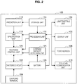
- FIG. 2 is a block diagram illustrating the configuration of the mobile phone 100.
- the mobile phone 100 according to the embodiment of the present disclosure includes a cellular communication unit 110 in addition to the display unit 102, the light emitting unit 106, and the touchscreen 108 that have been described above.
- the display unit 102 displays information related to functions of the mobile phone 100 and applications executed by the mobile phone 100.
- the display unit 102 may be a liquid crystal display or an organic electro-luminescence (EL) display.
- the touchscreen 108 is used by the user to operate the functions and applications of the mobile phone 100.
- the touchscreen 108 may be externally attached on the liquid crystal display or the organic EL display, or may be integrated with the liquid crystal display or the organic EL display.
- the light emitting unit 106 is used for showing a state of the mobile phone 100.
- the light emitting unit 106 may emit light in different colors in accordance with states of the mobile phone 100.
- the light emitting unit 106 may include a light emitting diode (LED).
- the cellular communication unit 110 is used for communicating with other devices.
- the mobile phone 100 is connected to a mobile phone network, the Internet, or the like when the cellular communication unit 110 communicates with a base station of a mobile network.
- the cellular communication unit 110 may be a wireless communication interface designed by the 3GPP such as Long-Term Evolution (LTE).
- LTE Long-Term Evolution
- the mobile phone 100 includes a processing unit 112, a storage unit 114, a prediction unit 116, and a time specification unit 118.
- the processing unit 112 is connected to respective units of the mobile phone 100 and executes various processes.
- the processing unit 112 executes the functions and applications of the mobile phone 100. Examples of the functions and applications of the mobile phone 100 include e-mail, short message, a social networking service, photography, music reproduction, a browsing function, map display, an alarm clock function, a calendar function, and the like.
- the processing unit 112 generates information to be displayed on the display unit 102, and processes signals from the touchscreen 108.
- the storage unit 114 stores various kinds of data.
- the storage unit 114 stores information related to an operating system (OS) used by the mobile phone 100, data used by the prediction unit 116, information related to the applications executed by the mobile phone 100, and the like.
- the prediction unit 116 predicts a chargeable time period from a time when a charger is connected to the mobile phone 100 to a time when discharge from the battery 126 will start.
- the time specification unit 118 specifies a time (timing) when the discharge from the battery 126 will start, on the basis of the chargeable time period predicted by the prediction unit 116. A method for predicting the chargeable time period will be described later.
- the mobile phone 100 includes a charging control unit 120, a charging circuit 122, a charged capacity detection unit 124, and the battery 126.
- the charging control unit 120 performs charging suppression control (to be described later) on the charging circuit 122 on the basis of a discharge starting time specified by the time specification unit 118, the charged capacity of the battery 126 detected by the charged capacity detection unit 124, and the like.
- the charged capacity detection unit 124 may determine the charged capacity of the battery 126 by detecting a voltage and a current of the battery 126, or may determine the charged capacity of the battery 126 by measuring inflowing and outflowing currents of the battery 126.
- the charging circuit 122 switches electric power feeding paths under the control of the charging control unit 120. In other words, when the electric power feeding path is set on the battery side under the control of the charging control unit 120, the charging circuit 122 charges the battery 126. When the electric power feeding path to the battery 126 is disconnected, charging of the battery 126 stops. In addition, when the electric power feeding path is set on the charging control unit 120 side, the charging circuit 122 feeds electric power from the charging terminal 104 to the respective units of the mobile phone 100 without passing through the battery 126.
- FIG. 3 is a diagram illustrating a standard charging method that is compared with the charging suppression control according to the present disclosure.
- the battery 126 is continuously charged until the battery 126 is fully charged (100%) when a charger is connected to the charging terminal 104 of the mobile phone 100. Therefore, in the standard charging method, the battery 126 is maintained with a highly charged capacity for a long time until a time point P at which a user starts using the mobile phone 100 as illustrated in FIG. 3 (in other words, until a time point at which the charger is disconnected from the charging terminal 104 of the mobile phone 100) after the battery 126 is fully charged. As described above, such a situation is called the overcharged state in general. The performance of the battery 126 deteriorates when the overcharged state is continued.
- the information processing device performs charging suppression control as illustrated in FIG. 4 .
- the charging suppression control it is possible to specify a time point P4 at which the charger is disconnected from the charging terminal 104 of the mobile phone 100 when the charger is connected to the charging terminal 104 of the mobile phone 100 at a time point P0.
- the battery 126 is charged from an initial value to a preparatorily charged capacity T that is a predetermined charged capacity (such as 90% of a fully charged capacity).
- a predetermined charged capacity such as 90% of a fully charged capacity.
- the charging control unit 120 controls the charging circuit 122 such that the electric power feeding path to the battery 126 is disconnected. Accordingly, electric power from the charger is directly fed to the respective units of the mobile phone 100 via the charging control unit 120.
- the charged capacity of the battery 126 is maintained at the preparatorily charged capacity (threshold T) until a time point P2.
- the preparatorily charged capacity is a predetermined threshold.
- the time point P2 is obtained by subtracting a margin and a time it takes to charge the battery 126 from the charged capacity T to the fully charged capacity, from the specified discharge staring time.
- charging of the battery 126 is restarted at the time point P2.
- a fixed value may be calculated from characteristics of the battery, or the time obtained by subtracting the margin and the time it takes to charge the battery 126 from the charged capacity T to the fully charged capacity may be calculated from a use history of the battery.
- the battery 126 When charging of the battery 126 is restarted at P2, the battery 126 is fully charged at a time point P3.
- the time period between P3 and P4 is a margin that is set for certainly charging the battery 126 from the preparatorily charged capacity to the fully charged capacity.
- the margin is set to deal with change in the time it takes to charge the battery 126 from the preparatorily charged capacity to the fully charged capacity due to a state (such as a temperature) of the mobile phone 100.
- the time it takes to charge the battery 126 from the preparatorily charged capacity to the fully charged capacity varies depending on charging modes of the battery 126.
- the charging modes of the battery 126 include a quick charging mode and a mode for charging the battery 126 more gently as the charged capacity of the battery 126 approaches 100%, for example.
- the information processing device performs the charging suppression control such that charging of the battery 126 stops at the preparatorily charged capacity and the charging restarts on the basis of the specified discharge staring time. Accordingly, it is possible to shorten a time period in which the battery 126 is maintained in the overcharged state, and it is possible to obtain the battery 126 with the fully charged capacity when the user wants to use the information processing device. Therefore, it is possible to provide the charging method that is convenient for users.
- the charging suppression control it may be possible to determine whether or not a time interval between the time point (P0) at which charging starts and the time point (P4) at which the charger is predicted to be discharged from the charging terminal 104 is a predetermined time period or longer.
- the chargeable time period between P0 and P4 in which the battery 126 is predicted to be chargeable is the predetermined time period or longer, it is possible to perform the above-described charging control. Accordingly, in the case where the chargeable time period is too short to perform the above-described charging suppression control, the charging suppression control is not performed but standard charging is carried out. Accordingly, by temporarily stopping the charging, it is possible to decrease a possibility that the battery 126 is not fully charged. Details of the chargeable time period will be described later.
- FIG. 5 is a diagram illustrating an example of a relation between a time when a user starts charging the mobile phone 100 and a time when the user starts using the mobile phone 100.
- the user starts charging the mobile phone 100 at 10 o'clock on Monday, and ends the charging at 16 o'clock.
- FIG. 5 illustrates an example of a relation between a time when a user starts charging the mobile phone 100 and a time when the user starts using the mobile phone 100.
- start charging means that the user connects a charger to the charging terminal 104 of the mobile phone 100 to charge the mobile phone 100
- start discharging means that the user disconnects the charger from the charging terminal 104 of the mobile phone 100 to use the mobile phone 100.
- the prediction unit 116 predicts the chargeable time period on the basis of charge/discharge time information related to the time when the charger is connected to the charging terminal 104 of the mobile phone 100 and the time when the charger is disconnected from the charging terminal 104 as illustrated in FIG. 5 .
- the prediction unit 116 causes the storage unit 114 to store the charge/discharge time information related to the charge staring time and the discharge starting time illustrated in FIG. 5 .
- the prediction unit 116 predicts that discharge from the battery 126 will start at 16 o'clock on Monday, and predicts the chargeable time period on the basis of such information.
- the prediction unit 116 causes the storage unit 114 to store the charge/discharge time information for each day of one or more week, and predicts the chargeable time period on the basis of the charge/discharge time information of a corresponding day of the week.
- FIG. 6 is a diagram illustrating an example of the chargeable time period that the prediction unit 116 derives.
- FIG. 6 illustrates how long the charging is possible when charging of the mobile phone 100 is started at respective times represented by a horizontal axis.
- FIG. 6 illustrates a chargeable time period that the prediction unit 116 derives in the case where charging often starts around 10 o'clock and discharge from the battery 126 often starts around 16 o'clock.
- the prediction unit 116 predicts that the chargeable time period is 6 hours when charging starts at 10 o'clock.
- the chargeable time period gets shortened as the charge staring time approaches 16 o'clock, at which the battery 126 will start discharge.
- FIG. 7 to FIG. 9 are diagrams illustrating a process of learning the chargeable time periods illustrated in FIG. 6 .
- FIG. 7 is a diagram illustrating states on respective days of a week before the learning starts.
- FIG. 8 is a diagram illustrating data related to chargeable time periods after a lapse of 2 days since the prediction unit 116 has started learning the chargeable time periods.
- FIG. 9 is a diagram illustrating data related to chargeable time periods after a lapse of one week since the prediction unit 116 has started learning the chargeable time periods.
- the prediction unit 116 derives the chargeable time periods for the respective days of the week.
- the storage unit 114 stores data related to the chargeable time periods illustrated in FIG. 9 .
- the prediction unit 116 predicts how long the charging is possible on the basis of data related to the times when the charger is connected to the mobile phone 100 and the chargeable time periods stored in the storage unit 114.
- the charging control unit 120 it is possible for the charging control unit 120 to perform the charging suppression control according to the present disclosure in the case where the chargeable time period is a predetermined time period or longer. By using the chargeable time periods as described above, it is possible to prevent the battery 126 from being charged insufficiently because of a too short chargeable time period when the charging suppression control is performed.
- the prediction unit 116 may learn a chargeable time period by using charge/discharge time information for two weeks. This is because recent batteries have large capacities and it is considered that a user charges the battery 126 every two days, for example. In other words, in the case of learning a chargeable time period by using the charge/discharge time information for one week, there may be a date (day of the week) when it is impossible to obtain charge/discharge time information. To prevent such a problem from occurring, for example, it may be possible to learn a chargeable time period by using charge/discharge time information of a corresponding day of a previous week with regard to charge/discharge time information of a date when the charge/discharge time information has not been obtained.
- the prediction unit 116 may learn a chargeable time period by using charge/discharge time information for four weeks. In addition, it is also possible for the prediction unit 116 to differently weight pieces of charge/discharge time information for the different weeks and derive chargeable time periods. For example, the prediction unit 116 may derive the chargeable time periods by multiplying a piece of the charge/discharge time information on four weeks ago last Tuesday by 1, multiplying a piece of the charge/discharge time information on three weeks ago last Tuesday by 2, multiplying a piece of the charge/discharge time information on two weeks ago last Tuesday by 3, and multiplying a piece of the charge/discharge time information on one week ago last Tuesday by 4.
- the prediction unit 116 learns chargeable time periods by using information related to nonbusiness days stored in the storage unit 114.
- the behavior of the user often differs between nonbusiness days and business days. For example, it is considered that the user wakes up at different times between nonbusiness days and business days.
- the prediction unit 116 learns a chargeable time period on a nonbusiness day by using charge/discharge time information on nonbusiness days, and learns a chargeable time period on a business day by using charge/discharge time information on business days.
- the prediction unit 116 may determine a country by using positional information that has been acquired, and learn chargeable time periods by using information related to holidays in the country. Accordingly, it is possible to predict precise chargeable time periods in accordance with behavior of a user on nonbusiness days or behavior of the user on business days.
- Step S100 in FIG. 10 charging starts when a charger is connected to the charging terminal 104 of the mobile phone 100.
- Step S102 the prediction unit 116 predicts a chargeable time period and transmits the predicted chargeable time period to the time specification unit 118.
- the prediction unit 116 predicts the chargeable time period by using data related to the chargeable time periods described with reference to FIG. 6 to FIG. 9 .
- the time specification unit 118 receives the predicted chargeable time period from the prediction unit 116 and specifies a discharge starting time by adding the received chargeable time period to a current time.
- Step S104 the charging control unit 120 determines whether or not the chargeable time period is a predetermined time period or more (such as four hours or more) on the basis of the chargeable time period predicted by the prediction unit 116.
- the charging control unit 120 controls the charging circuit 122 such that the standard charging is carried out (S108).
- the charging control unit 120 it is possible to carry out the standard charging even in the case where the chargeable time period is too short for the charging control unit 120 to perform the charging suppression control.
- Step S106 the charging control unit 120 determines that the chargeable time period is the predetermined time period or more in Step S104.
- the charging control unit 120 determines whether or not the charged capacity of the battery 126 reaches a preparatorily charged capacity on the basis of the charged capacity of the battery 126 detected by the charged capacity detection unit 124.
- the charging control unit 120 controls the charging circuit 122 such that charging of the battery 126 temporarily stops in Step S110.
- the time specification unit 118 determines whether or not the current time is a predetermined period of time (such as 90 minutes) before the discharge starting time.
- the charging control unit 120 controls the charging circuit 122 such that charging of the battery 126 is restarts in Step S114.
- Step S116 the charging control unit 120 determines whether or not the battery 126 is fully charged on the basis of the charged capacity of the battery 126 detected by the charged capacity detection unit 124.
- the charging control unit 120 determines that the battery 126 is fully charged in Step S116, the charging control unit 120 controls the charging circuit 122 such that charging of the battery 126 stops, and the process ends.
- the time specification unit 118 may specify a time when charging of the battery 126 is to be restarted on the basis of a state of the mobile phone 100.
- the state of the mobile phone 100 is a state based on a temperature measured by a temperature sensor included in the mobile phone 100, for example.
- the time specification unit 118 may specify the time when charging of the battery 126 is to be restarted on the basis of a charging mode of the mobile phone 100.
- the time specification unit 118 may specify the time when charging of the battery is to be restarted to shorten the margin (the time period between P3 and P4 in FIG. 4 ) set for certainly charging the battery 126 from the preparatorily charged capacity to the fully charged capacity.
- the charging modes of the battery 126 include the quick charging mode and the mode for charging the battery 126 more gently as the charged capacity of the battery 126 approaches 100%. In other words, it is possible to shorten a time period in which the battery 126 is maintained in the overcharged state, when the time specification unit 118 changes a time when charging is to be restarted on the basis of the state or the charging mode of the mobile phone 100.
- the time specification unit 118 lengthens the above-described margin in the case where it takes a long time to charge the battery 126 from the preparatorily charged capacity to the fully charged capacity, in accordance with a state or a charging mode of the mobile phone 100.
- the time specification unit 118 shortens the above-described margin in the case where it takes a short time to charge the battery 126 from the preparatorily charged capacity to the fully charged capacity.
- the storage unit 114 may store a time it takes to charge the battery 126 from the preparatorily charged capacity to the fully charged capacity and a temperature measured by the temperature sensor of the mobile phone 100 in association with each other. The time specification unit 118 may use such data to specify a time when charging is to be restarted. Therefore, it is possible to set a margin that is appropriate for the mobile phone 100 or an ambient temperature of the mobile phone 100.
- the processing unit 112 may cause the display unit 102 to display a display indicating that the above-described charging suppression control is being performed.
- FIG. 11 is a diagram illustrating a charging mode display icon 130 indicating that the charging suppression control is being performed.
- the charging mode display icon 130 may be displayed in a status bar 128 displayed on the display unit 102.
- the display unit 102 may display a dialogue indicating that the charging suppression control is being performed. As described above, by displaying a display indicating that the charging suppression control is being performed, it is possible for a user to easily recognize a charging mode that is currently used.
- the light emitting unit 106 it is also possible to use the light emitting unit 106 to indicate that the above-described charging suppression is being performed. Specifically, it is possible for the light emitting unit 106 to change a color of light to be emitted in accordance with a charging mode that is currently set. For example, the light emitting unit 106 may emit light in red in the case of carrying out the standard charging in which the charging suppression control according to the present disclosure is not performed. In addition, the light emitting unit 106 may emit light in greed in the case of carrying out charging under the charging suppression control according to the present disclosure. According to such configurations, it is possible for the user to easily recognize a charging mode even in a state in which the display unit 102 is not lit (such as in a sleep state).
- the chargeable time period is predicted and the discharge starting time is specified when charging starts.
- the standard charging is carried out until the battery 126 reaches the preparatorily charged capacity.
- the chargeable time period may be predicted and the discharge starting time may be specified when the charged capacity of the battery 126 reaches the preparatorily charged capacity.
- FIG. 12 is a diagram illustrating another control example of the charging suppression control according to the present disclosure.
- FIG. 12 and FIG. 4 are compared, it is understood that processes of charging the battery 126 from an initial value to a preparatorily charged capacity (threshold T) are different between FIG. 12 and FIG. 4 .
- the battery 126 is continuously charged from the initial value to the preparatorily charged capacity in FIG. 4 , while the battery 126 is charged in stages from the initial value to the preparatorily charged capacity in FIG. 12 .
- the method for charging the battery 126 from the initial value to the preparatorily charged capacity may be a method for repeating start and stop of charging at predetermined time intervals (every hour, for example).
- the method for charging the battery 126 from the initial value to the preparatorily charged capacity may be a method for repeating start and stop of charging every time the charged capacity reaches predetermined charged capacities.
- the charging control unit 120 may perform control such that charging stops every time the charged capacity of the battery 126 increases by 10% and charging restarts after a predetermined time period. Specifically, in the case where the initial value of the charged capacity of the battery 126 is 38%, the charging control unit 120 may temporarily stop charging when the charged capacity becomes 48%, 58%, and 68%.
- the charging control unit 120 may repeat start and stop of charging every time the battery 126 is charged by a predetermined charged capacity.
- the charging control unit 120 may perform control such that charging stops every time the battery 126 is charged by 10% and charging restarts after a predetermined time period. Specifically, in the case where the initial value of the charged capacity of the battery 126 is 38%, the charging control unit 120 may temporarily stop charging when the charged capacity becomes 40%, 50%, and 60%.
- the battery 126 is maintained with a low charged capacity for a long time in the case where the battery 126 is charged in stages from the initial value to the preparatorily charged capacity. In other words, it is possible to prolong a time period in which the battery 126 is maintained with a charged capacity that is the preparatorily charged capacity (predetermined threshold T) or less. Accordingly, it is possible to more effectively prevent the battery 126 from deteriorating.
- FIG. 13 is a diagram illustrating an example of a display screen used for canceling the above-described charging suppression control according to the present disclosure.
- an area 132 includes a display similar to the charging mode display icon 130 described with reference to FIG. 11 , and includes a display of a message indicating that the charging suppression control is being performed.
- the area 132 includes a display of the specified discharge staring time. By tapping the area 132, the user is capable of canceling the charging suppression control and charging the battery 126 in the standard charging mode.
- FIG. 14 is a diagram illustrating charging control performed in the case where the charging suppression control according to the present disclosure is canceled.
- FIG. 14 illustrates an example in which the user cancels the charging suppression control at a time point P5. Note that, in FIG. 14 , a solid line represents control performed in the case where the charging suppression control is continuously performed, and a dotted line represents control performed in the case where the charging suppression control is canceled.
- charging suppression control As described above, under the charging suppression control according to the present disclosure, charging is temporarily stopped at the time point P1 when the battery 126 is charged to the preparatorily charged capacity. Next, the charged capacity of the battery 126 is maintained at the preparatorily charged capacity until the time point P5, and the charging suppression control is canceled at the time point P5. When the charging suppression control is canceled, charging restarts at the time point of the cancellation (time point P5), and the battery 126 is fully charged at a time point P6. According to the above-described configuration of the mobile phone 100, it is possible for the user to easily cancel the charging suppression control and handle the sudden change in schedules.
- the mobile phone 100 includes a movement sensor that detects movement of the mobile phone 100 such as an acceleration sensor or a gyro sensor, it is possible for the user to cancel the charging suppression control by shaking the mobile phone 100 with a predetermined acceleration or more. According to the above-described configuration of the mobile phone 100, it is possible for the user to cancel the charging suppression control more quickly without operating a display content displayed on the display unit 102. This is very convenient for a user who has to handle sudden change in his/her schedule.
- the display unit 102 may display a display (such as a message) notifying a user that the charging suppression control has been canceled.
- a display such as a message
- the light emitting unit 106 it is also possible for the light emitting unit 106 to emit light in a different color to notify the user that the charging suppression control has been canceled, as described above.
- the user may intentionally disconnect a charger from the mobile phone 100, or may accidentally disconnect the charger from the mobile phone 100.
- the user intentionally disconnects the charger from the mobile phone 100, it is considered that the user activates an application in the mobile phone 100 to check a message from another person during charging.
- the user accidentally disconnects the charger from the mobile phone 100 it is considered that the user accidentally drops the mobile phone 100 and the charger is disconnected from the mobile phone 100.
- FIG. 15 illustrates an example in which a charger is disconnected from the charging terminal 104 of the mobile phone 100 at a time point P7. Note that, in FIG. 15 , a dotted line represents control performed in the case where the charger is disconnected from the charging terminal 104 of the mobile phone 100 before the battery 126 is fully charged under the charging suppression control, and a solid line represents control performed in the case where the charger is not disconnected.
- the battery 126 is charged from the time point P8 in FIG. 15 until the charged capacity of the battery 126 becomes the preparatorily charged capacity (threshold T). Subsequently, the charging is stopped until the time point P2 that is a predetermined period of time before the discharge starting time that is initially specified by the time specification unit 118.
- the prediction unit 116 may predict a chargeable time period again at the time point P8 at which the charger is reconnected to the mobile phone 100, and the charging control unit 120 may perform the charging suppression control again on the basis of the predicted chargeable time period.
- the process performed under the charging suppression control according to the present disclosure in the case where a charger is disconnected from the charging terminal 104 of the mobile phone 100 before the battery 126 is fully charged has been described above.
- charging suppression control using accuracy will be described.
- the accuracy is calculated by comparing the discharge starting time specified by the time specification unit 118 with a time when the user has actually disconnected the charger from the mobile phone 100, for example.
- the charging control unit 120 determines whether or not to perform the charging suppression control by using the accuracy of the discharge starting time specified by the time specification unit 118.
- the prediction unit 116 determines whether or not there is an interval of a predetermined time period or more (such as 30 minutes or more) between the discharge staring time specified by the time specification unit 118 and the time when the user has actually disconnected the charger from the mobile phone 100.
- a predetermined time period or more such as 30 minutes or more
- the chargeable time period has been erroneously predicted in the case where there is an interval of the predetermined time period or more between the specified discharge staring time and the time when the user has actually disconnected the charger from the mobile phone 100.
- the predicted chargeable time period is correct in the case where the interval between the specified discharge staring time and the time when the user has actually disconnected the charger from the mobile phone 100 is a predetermined time period or less.
- the prediction unit 116 may draw comparisons between the above-described times for a week. Subsequently, the charging control unit 120 performs charging suppression control in the case where an accuracy rate of the comparisons is a predetermined value or more (such as 80% or more).
- FIG. 16 is a flowchart illustrating operation under the charging suppression control using the accuracy.
- Step S200 to Step S204 correspond to Step S100 to Step S104 in FIG. 10 .
- Step S206 the charging control unit 120 receives accuracy from the prediction unit 116 and determines whether or not the accuracy is a predetermined value or more.
- the process proceeds to Step S210, and the charging control unit 120 performs the charging suppression control according to the present disclosure.
- Step S212 when it is determined that the accuracy is less than the predetermined value in Step S206, the process proceeds to Step S212 and the charging control unit 120 carries out the standard charging.
- the charging suppression control in the case where a chargeable time period is predicted with certain accuracy.
- the applications executed by the mobile phone 100 include an application in which times or schedules are set.
- Examples of the application in which times are set include an application having an alarm clock function and an application having a calendar function for inputting schedules of a user.
- a time set by the alarm clock function is deemed to be a time when the user will start using the mobile phone 100.
- the time set by the alarm clock function is deemed to be a time when the mobile phone 100 is disconnected from the charger and the battery 126 starts discharge.
- a starting time of the specific schedule is also deemed to be the time when the mobile phone 100 is disconnected from the charger and the battery 126 starts discharge.
- the time specification unit 118 may specify the time set by the alarm clock function or the time when the specific schedule is to be executed as a discharge starting time for performing the charging suppression control according to the present disclosure.
- the chargeable time period specified on the basis of the time set by the alarm clock function and the time when the specific schedule is to be executed is prioritized over a discharge starting time based on a chargeable time period predicted by the prediction unit 116.
- FIG. 17 is a flowchart illustrating a process of the charging suppression control using information from an application.
- Step S300 charging starts when a charger is connected to the charging terminal 104 of the mobile phone 100.
- Step S302 the prediction unit 116 predicts a chargeable time period.
- the time specification unit 118 receives the chargeable time period predicted by the prediction unit 116 and specifies a discharge starting time.
- Step S304 the time specification unit 118 determines whether or not a time for executing the alarm clock function is set by the application having the alarm clock function.
- the process proceeds to Step S306.
- Step S306 the time specification unit 118 specifies the time set for executing the alarm clock function, as a discharge starting time.
- the charging control unit 120 determines whether or not the chargeable time period is a predetermined time period or longer, on the basis of the discharge starting time specified in Step S306 by using the information from the application having the alarm clock function.
- Step S308 the time specification unit 118 determines whether or not a specific schedule is set by an application having a calendar function.
- Step S310 the time specification unit 118 specifies the starting time of the set specific schedule as a discharge starting time.
- the charging control unit 120 determines whether or not the chargeable time period is a predetermined time period or longer, on the basis of the discharge starting time specified in Step S310 by using the information from the application having the calendar function.
- the process proceeds to S312.
- the charging control unit 120 determines whether a chargeable time period is a predetermined time period or longer, on the basis of the chargeable time period predicted by the prediction unit 116 in Step S302. Subsequently, processes similar to the charging suppression control described with reference to FIG. 10 are performed.
- the time set in the application may be prioritized over a discharge starting time based on the chargeable time period predicted by the prediction unit 116, and it is possible to use the time set in the application as a discharge starting time. Accordingly, it is possible to perform the charging suppression control according to the present disclosure on the basis of a time or schedule set by the user, the time and schedule being considered to have higher reliabilities.
- the charging suppression control based on information from an application in which a specific time or schedule is set has been described above. Next, charging suppression control based on information from another information processing device will be described.
- FIG. 18 is a diagram illustrating a wristband-type small terminal 200 that is connected to the mobile phone 100 through short-range wireless communication.
- the small terminal 200 is connected to the mobile phone 100 by using a short-range wireless communication interface such as Bluetooth (registered trademark).
- the small terminal 200 includes a sensor that detects movement of a user who is wearing the small terminal 200.
- the sensor that detects movement of the user may be an acceleration sensor or a gyro sensor, for example.
- the small terminal 200 is capable of calculating an amount of activity of the user on the basis of information from the above-described sensor that detects movement of the user.
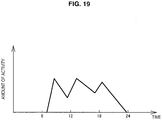
- FIG. 19 is a diagram illustrating an example of the amount of activity of the user calculated by the small terminal 200. In the example illustrated in FIG. 19 , the amount of activity of the user increases around 7 o'clock, 12 o'clock, and 18 o'clock.
- the amount of activity has increased around 7 o'clock because the user has woken up, for example.
- the amount of activity has increased around 12 o'clock because the user has gone out to lunch.
- the amount of activity has increased around 18 o'clock because the user has gotten back home.
- Such behavior of the user like wake-up, going out, and coming home is behavior that is closely related to the user's behavior of disconnecting the mobile phone 100 from the charger.
- the prediction unit 116 may learn a chargeable time period by using a time when a large amount of activity of the user is calculated by the small terminal 200 instead of a time when the battery 126 will start discharge. At this time, the mobile phone 100 stores the calculated amount of activity. Subsequently, the prediction unit 116 learns the chargeable time period while using the time when the large amount of activity is obtained as the a time when the battery 126 will start discharge. In addition, in a way similar to the above-described examples, it is possible for the prediction unit 116 to learn a chargeable time period by using data of amounts of activities for one or more weeks.
- the mobile phone 100 it is possible to perform the charging suppression control on the basis of behavior of a user. Therefore, it is possible to suppress overcharging and it is possible to fully charge battery 126 when the user is expected to perform behavior of disconnecting the charger from the mobile phone 100.
- a chargeable time period may be predicted at a time point (P0 in FIG. 4 ) at which the charging terminal 104 of the mobile phone 100 is connected to a charger, and may be predicted again at a time point (PI in FIG. 4 ) at which the battery 126 is charged to the preparatorily charged capacity.
- the prediction unit 116 it is possible for the prediction unit 116 to predict a chargeable time period more than once. Accordingly, the charging suppression control is performed in the case where a user starts charging at a time (such as 5 o'clock in FIG. 6 ) when it is initially determined that a chargeable time period is short, and the charging continues until a time (such as 10 o'clock in FIG. 6 ) when it is determined that the chargeable time period is a predetermined time period or more, for example.
- the prediction unit 116 predicts the chargeable time period by using data related to chargeable time periods stored in the storage unit 114.
- the prediction unit 116 may predict a discharge staring time instead of a chargeable time period, and predict the chargeable time period by comparing the predicted discharge staring time with a time when the charger is connected to the charging terminal 104 of the mobile phone 100.
- the time specification unit 118 may specify a discharge starting time by using the discharge starting time predicted by the prediction unit 116.
- the example of using the application having the alarm clock function and the application having the calendar function has been described with reference to FIG. 17 .
- the application in which times or schedules are set is not limited thereto.
- the application having the alarm clock function is prioritized over the application having the calendar function when specifying the discharge starting time.
- priority levels of the applications to be used are not limited thereto.
- the mobile phone 100 may be configured to display a setting screen for setting the priority levels of the applications.
- the information processing device performs the charging suppression control such that charging of the battery 126 stops at the preparatorily charged capacity and the charging restarts on the basis of the specified discharge staring time. Accordingly, it is possible to shorten a time period in which the battery 126 is maintained in the overcharged state, and it is possible to obtain the battery 126 with the fully charged capacity when the user wants to use the information processing device. Therefore, it is possible to provide the charging method that is convenient for users.
- the information processing device specifies a discharge starting time on the basis of information from an application in which a time is set. Accordingly, it is possible to perform the charging suppression control according to the present disclosure on the basis of a time set by the user, the time being considered to have higher reliabilities.
- the information processing device specifies a discharge starting time on the basis of an amount of activity of a user obtained from information from another information processing device. Therefore, it is possible to perform the charging suppression control based on behavior of the user.
- present technology may also be configured as below.
Landscapes
- Engineering & Computer Science (AREA)
- Power Engineering (AREA)
- Manufacturing & Machinery (AREA)
- Chemical & Material Sciences (AREA)
- Chemical Kinetics & Catalysis (AREA)
- Electrochemistry (AREA)
- General Chemical & Material Sciences (AREA)
- Theoretical Computer Science (AREA)
- Evolutionary Computation (AREA)
- Data Mining & Analysis (AREA)
- Computational Linguistics (AREA)
- Physics & Mathematics (AREA)
- Computing Systems (AREA)
- General Engineering & Computer Science (AREA)
- General Physics & Mathematics (AREA)
- Mathematical Physics (AREA)
- Software Systems (AREA)
- Artificial Intelligence (AREA)
- Charge And Discharge Circuits For Batteries Or The Like (AREA)
- Telephone Function (AREA)
Applications Claiming Priority (2)
| Application Number | Priority Date | Filing Date | Title |
|---|---|---|---|
| JP2016138673 | 2016-07-13 | ||
| PCT/JP2017/013969 WO2018012055A1 (fr) | 2016-07-13 | 2017-04-03 | Dispositif de traitement d'informations, système de traitement d'informations et procédé de charge |
Publications (2)
| Publication Number | Publication Date |
|---|---|
| EP3484010A1 true EP3484010A1 (fr) | 2019-05-15 |
| EP3484010A4 EP3484010A4 (fr) | 2020-01-08 |
Family
ID=60952013
Family Applications (1)
| Application Number | Title | Priority Date | Filing Date |
|---|---|---|---|
| EP17827189.6A Pending EP3484010A4 (fr) | 2016-07-13 | 2017-04-03 | Dispositif de traitement d'informations, système de traitement d'informations et procédé de charge |
Country Status (5)
| Country | Link |
|---|---|
| US (1) | US11336107B2 (fr) |
| EP (1) | EP3484010A4 (fr) |
| JP (1) | JP6926081B2 (fr) |
| CN (2) | CN109417300B (fr) |
| WO (1) | WO2018012055A1 (fr) |
Cited By (4)
| Publication number | Priority date | Publication date | Assignee | Title |
|---|---|---|---|---|
| EP3518380A1 (fr) * | 2018-01-25 | 2019-07-31 | Samsung Electronics Co., Ltd. | Dispositif électronique incluant une batterie et son procédé de commande de charge |
| WO2021015730A1 (fr) * | 2019-07-22 | 2021-01-28 | Hewlett-Packard Development Company, L.P. | Charge de batteries à base de calendrier |
| WO2022081190A1 (fr) * | 2020-10-13 | 2022-04-21 | Google Llc | Dispositif électronique de charge jusqu'à un niveau de charge maximal réduit |
| EP4145666A4 (fr) * | 2020-06-05 | 2024-03-27 | Huawei Tech Co Ltd | Procédé de gestion de charge, dispositif électronique et système |
Families Citing this family (6)
| Publication number | Priority date | Publication date | Assignee | Title |
|---|---|---|---|---|
| CN107681713B (zh) * | 2017-09-13 | 2021-10-22 | 惠州Tcl移动通信有限公司 | 一种多模式充电控制方法、移动终端及存储介质 |
| US11862772B2 (en) * | 2018-03-29 | 2024-01-02 | Canal Electronics LLC | User-defined battery recharging systems and methods |
| CN111564877A (zh) * | 2020-04-30 | 2020-08-21 | 华为技术有限公司 | 用于充电管控的方法和装置 |
| CA3217299A1 (fr) * | 2021-05-04 | 2022-11-10 | Tung Nguyen | Systemes et procedes de commande de batterie |
| CA3159864A1 (fr) | 2021-05-13 | 2022-11-13 | Exro Technologies Inc. | Methode et appareil d'entrainement des bobines d'une machine electrique multiphasee |
| CN113659655B (zh) * | 2021-07-26 | 2024-05-10 | 珠海格力电器股份有限公司 | 电子设备的充电方法、装置、电子设备和存储介质 |
Family Cites Families (30)
| Publication number | Priority date | Publication date | Assignee | Title |
|---|---|---|---|---|
| CN1076889C (zh) * | 1994-08-09 | 2001-12-26 | 日本电池株式会社 | 制备镍-氢电池的方法 |
| JPH09168240A (ja) * | 1995-12-12 | 1997-06-24 | Toyota Motor Corp | バッテリ充電装置 |
| JP2002142378A (ja) * | 2000-10-31 | 2002-05-17 | Canon Inc | 充電装置、方法及び記憶媒体 |
| JP2004236426A (ja) | 2003-01-30 | 2004-08-19 | Fujitsu Support & Service Kk | バッテリー充放電制御装置 |
| JP2005027435A (ja) * | 2003-07-02 | 2005-01-27 | Sony Corp | 充電装置 |
| US7446509B2 (en) * | 2004-05-08 | 2008-11-04 | Gem Power, Llc | Intelligent battery charging system |
| US20060226807A1 (en) * | 2005-03-30 | 2006-10-12 | Simpson Russell L | Method and apparatus for maximizing battery charge |
| US7991513B2 (en) * | 2007-05-08 | 2011-08-02 | Ecodog, Inc. | Electric energy bill reduction in dynamic pricing environments |
| US7782021B2 (en) * | 2007-07-18 | 2010-08-24 | Tesla Motors, Inc. | Battery charging based on cost and life |
| WO2009047918A1 (fr) * | 2007-10-11 | 2009-04-16 | Panasonic Corporation | Circuit de génération de haute tension, dispositif de ponction et dispositif d'analyse sanguine |
| US20090289603A1 (en) * | 2008-05-21 | 2009-11-26 | Apple Inc. | Method and apparatus for maintaining a battery in a partially charged state |
| JP4932810B2 (ja) * | 2008-10-20 | 2012-05-16 | マツダ株式会社 | 電動車両用バッテリの充電方法およびその装置 |
| US20100123436A1 (en) * | 2008-11-14 | 2010-05-20 | Symbol Technologies, Inc. | Optimized lithium-ion battery charging |
| US8922329B2 (en) * | 2009-07-23 | 2014-12-30 | Qualcomm Incorporated | Battery charging to extend battery life and improve efficiency |
| CN102549875B (zh) * | 2009-08-11 | 2014-10-22 | 索尼公司 | 电子设备、对电子设备充电的方法、程序、充电控制装置以及充电控制方法 |
| JP2013031232A (ja) * | 2009-11-16 | 2013-02-07 | Sanyo Electric Co Ltd | 充電装置及び充電方法 |
| JP2011151891A (ja) * | 2010-01-19 | 2011-08-04 | Sony Corp | 二次電池の充電方法および充電装置 |
| US8638070B2 (en) * | 2010-05-21 | 2014-01-28 | Qnovo Inc. | Method and circuitry to adaptively charge a battery/cell |
| US20130285608A1 (en) * | 2011-01-06 | 2013-10-31 | Nec Corporation | Charging control device, charging control method, and program |
| JP5982736B2 (ja) * | 2011-03-30 | 2016-08-31 | ソニー株式会社 | 蓄電装置、蓄電方法およびプログラム |
| JP5516550B2 (ja) * | 2011-05-09 | 2014-06-11 | 株式会社デンソー | 車両用ナビゲーション装置 |
| JP5919506B2 (ja) * | 2011-09-20 | 2016-05-18 | パナソニックIpマネジメント株式会社 | 充電式電気機器 |
| US20140099614A1 (en) * | 2012-10-08 | 2014-04-10 | Lark Technologies, Inc. | Method for delivering behavior change directives to a user |
| JP2014176104A (ja) * | 2013-03-05 | 2014-09-22 | Funai Electric Co Ltd | 機器および充電制御方法 |
| JP6088858B2 (ja) * | 2013-03-12 | 2017-03-01 | シャープ株式会社 | 自走式機器 |
| WO2015056312A1 (fr) * | 2013-10-16 | 2015-04-23 | 一般財団法人日本自動車研究所 | Dispositif d'estimation de dégradation et procédé d'estimation de dégradation pour batteries lithium-ion |
| JP2015104139A (ja) * | 2013-11-20 | 2015-06-04 | 株式会社Wave Technology | 二次電池の充電方法およびそれを用いた充電装置 |
| JP6339690B2 (ja) * | 2014-09-29 | 2018-06-06 | シャープ株式会社 | 情報処理装置、情報処理装置の制御方法、および制御プログラム |
| US20160380440A1 (en) * | 2015-06-26 | 2016-12-29 | TEQ Charging, Inc. | Electric charging power management |
| US10250052B2 (en) * | 2015-12-03 | 2019-04-02 | Qualcomm Incorporated | Charge rate optimization for enhanced battery cycle life |
-
2017
- 2017-04-03 US US16/314,667 patent/US11336107B2/en active Active
- 2017-04-03 JP JP2018527393A patent/JP6926081B2/ja active Active
- 2017-04-03 CN CN201780041764.7A patent/CN109417300B/zh active Active
- 2017-04-03 CN CN202310354944.8A patent/CN116470609A/zh active Pending
- 2017-04-03 EP EP17827189.6A patent/EP3484010A4/fr active Pending
- 2017-04-03 WO PCT/JP2017/013969 patent/WO2018012055A1/fr unknown
Cited By (6)
| Publication number | Priority date | Publication date | Assignee | Title |
|---|---|---|---|---|
| EP3518380A1 (fr) * | 2018-01-25 | 2019-07-31 | Samsung Electronics Co., Ltd. | Dispositif électronique incluant une batterie et son procédé de commande de charge |
| US11056903B2 (en) | 2018-01-25 | 2021-07-06 | Samsung Electronics Co., Ltd. | Electronic device including battery and method of controlling charging thereof |
| EP3972076A1 (fr) * | 2018-01-25 | 2022-03-23 | Samsung Electronics Co., Ltd. | Dispositif électronique incluant une batterie et son procédé de commande de charge |
| WO2021015730A1 (fr) * | 2019-07-22 | 2021-01-28 | Hewlett-Packard Development Company, L.P. | Charge de batteries à base de calendrier |
| EP4145666A4 (fr) * | 2020-06-05 | 2024-03-27 | Huawei Tech Co Ltd | Procédé de gestion de charge, dispositif électronique et système |
| WO2022081190A1 (fr) * | 2020-10-13 | 2022-04-21 | Google Llc | Dispositif électronique de charge jusqu'à un niveau de charge maximal réduit |
Also Published As
| Publication number | Publication date |
|---|---|
| JP6926081B2 (ja) | 2021-08-25 |
| EP3484010A4 (fr) | 2020-01-08 |
| US20190334354A1 (en) | 2019-10-31 |
| CN116470609A (zh) | 2023-07-21 |
| US11336107B2 (en) | 2022-05-17 |
| CN109417300B (zh) | 2023-04-28 |
| CN109417300A (zh) | 2019-03-01 |
| JPWO2018012055A1 (ja) | 2019-04-25 |
| WO2018012055A1 (fr) | 2018-01-18 |
Similar Documents
| Publication | Publication Date | Title |
|---|---|---|
| US11336107B2 (en) | Information processing device, information processing system, and charging method | |
| US10652828B2 (en) | Electronic device for providing mode switching and a method thereof | |
| EP3574546B1 (fr) | Procédé de commande et dispositif électronique basés sur un état de fuite de batterie | |
| EP2610701B1 (fr) | Gestion d'alimentation électrique pour dispositifs électroniques portables | |
| US20150123595A1 (en) | Intelligent context based battery charging | |
| KR20160057091A (ko) | 전자 장치 및 그의 배터리 충방전 제어 방법 | |
| US20130103960A1 (en) | Method and device with intelligent power management | |
| US9391466B2 (en) | Method and device for battery-charging management | |
| US20130169219A1 (en) | Power supply management for portable electronic devices | |
| US20120001746A1 (en) | Vehicular electric charge control apparatus and emergency notification system | |
| US9438057B2 (en) | Drive control device, drive control method and drive control program | |
| WO2014189676A1 (fr) | Systèmes et procédés de surveillance d'activité sans fil avec notifications | |
| US11695291B2 (en) | Method to charge battery and electronic device including battery | |
| KR20190090474A (ko) | 배터리를 포함하는 전자 장치 및 이의 충전구간을 제어하는 방법 | |
| CN114977343A (zh) | 一种充电方法、装置、电子设备及存储介质 | |
| CN105659188A (zh) | 上下文功率管理 | |
| US11394223B2 (en) | Charging method, electronic equipment, and storage medium | |
| CN110581578B (zh) | 防止电池过充方法、装置和存储介质 | |
| WO2014023185A1 (fr) | Procédé et dispositif de gestion de charge de batterie | |
| US11209884B2 (en) | Information processing apparatus, information processing method, and program | |
| US20210088593A1 (en) | Charging reminding method for rechargeable device and memory | |
| US20180375344A1 (en) | Situational battery charging | |
| US9711982B2 (en) | Information notifying device | |
| KR20150016044A (ko) | 전자 장치에서 배터리 소모를 줄이기 위한 방법 | |
| EP3893320B1 (fr) | Procédé d'arrêt, appareil d'arrêt, terminal et support d'enregistrement |
Legal Events
| Date | Code | Title | Description |
|---|---|---|---|
| STAA | Information on the status of an ep patent application or granted ep patent |
Free format text: STATUS: THE INTERNATIONAL PUBLICATION HAS BEEN MADE |
|
| PUAI | Public reference made under article 153(3) epc to a published international application that has entered the european phase |
Free format text: ORIGINAL CODE: 0009012 |
|
| STAA | Information on the status of an ep patent application or granted ep patent |
Free format text: STATUS: REQUEST FOR EXAMINATION WAS MADE |
|
| 17P | Request for examination filed |
Effective date: 20190206 |
|
| AK | Designated contracting states |
Kind code of ref document: A1 Designated state(s): AL AT BE BG CH CY CZ DE DK EE ES FI FR GB GR HR HU IE IS IT LI LT LU LV MC MK MT NL NO PL PT RO RS SE SI SK SM TR |
|
| AX | Request for extension of the european patent |
Extension state: BA ME |
|
| DAV | Request for validation of the european patent (deleted) | ||
| DAX | Request for extension of the european patent (deleted) | ||
| A4 | Supplementary search report drawn up and despatched |
Effective date: 20191211 |
|
| RIC1 | Information provided on ipc code assigned before grant |
Ipc: H02J 7/00 20060101AFI20191205BHEP Ipc: H04M 1/00 20060101ALI20191205BHEP Ipc: H01M 10/48 20060101ALI20191205BHEP Ipc: H01M 10/44 20060101ALI20191205BHEP Ipc: H02J 7/04 20060101ALI20191205BHEP |
|
| RAP3 | Party data changed (applicant data changed or rights of an application transferred) |
Owner name: SONY GROUP CORPORATION |
|
| STAA | Information on the status of an ep patent application or granted ep patent |
Free format text: STATUS: EXAMINATION IS IN PROGRESS |
|
| STAA | Information on the status of an ep patent application or granted ep patent |
Free format text: STATUS: EXAMINATION IS IN PROGRESS |
|
| 17Q | First examination report despatched |
Effective date: 20211112 |